1
YASKAWA
Series SGMBH/SGDH
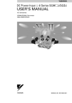
USER’S MANUAL
AC Servodrive (400 V, 22 to 55 kW)
SGMBH Servomotor
SGDH SERVOPACK
YASKAWA
MANUAL NO. SIE-S800-32.4
Copyright © 2002 YASKAWA ELECTRIC CORPORATION
All rights reserved. No part of this publication may be reproduced, stored in a retrieval system,
or transmitted, in any form, or by any means, mechanical, electronic, photocopying, recording,
or otherwise, without the prior written permission of Yaskawa. No patent liability is assumed
with respect to the use of the information contained herein. Moreover, because Yaskawa is constantly striving to improve its high-quality products, the information contained in this manual is
subject to change without notice. Every precaution has been taken in the preparation of this
manual. Nevertheless, Yaskawa assumes no responsibility for errors or omissions. Neither is
any liability assumed for damages resulting from the use of the information contained in this
publication.
About this Manual
This manual provides the following information for the Σ-II Series SGMBH/SGDH
Servodrives.
• Procedures for installing and wiring the servomotor and SERVOPACK.
• Procedures for trial operation of the Servodrive.
• Procedures for using functions and adjusting the servodrives.
• Procedures for using the built-in Panel Operator and the Hand-held Digital Operator.
• Ratings and specifications for standard models.
• Procedures for maintenance and inspection.
Intended Audience
This manual is intended for the following users.
• Those designing Σ-II Series servodrive systems.
• Those installing or wiring Σ-II Series servodrives.
• Those performing trial operation or adjustments of Σ-II Series servodrives.
• Those maintaining or inspecting Σ-II Series servodrives.
Description of Technical Terms
In this manual, the following terms are defined as follows:
• Servomotor = Σ-II Series SGMBH servomotor.
• SERVOPACK = Σ-II Series SGDH SERVOPACK.
• Servodrive = A set including a servomotor and Servo Amplifier.
• Servo System = A servo control system that includes the combination of a servodrive
with a host computer and peripheral devices.
Indication of Reverse Signals
In this manual, the names of reverse signals (ones that are valid when low) are written with a
forward slash (/) before the signal name, as shown in the following example:
• S-ON = /S-ON
• P-CON = /P-CON
iii
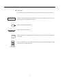
Visual Aids
The following aids are used to indicate certain types of information for easier reference.
IMPORTANT
INFO
EXAMPLE
Indicates important information that should be memorized, including precautions such as
alarm displays to avoid damaging the devices.
Indicates supplemental information.
Indicates application examples.
Indicates definitions of difficult terms or terms that have not been previously explained in
TERMS
this manual.
The text indicated by this icon explains the operating procedure using Hand-held type Digital Operator (Type: JUSP-OP02A-2).
JUSP-OP02A-2
iv
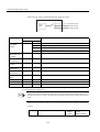
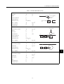
Related Manuals
Refer to the following manuals as required.
Also, keep this manual in a safe place so that it can be referred to whenever necessary.
Manual Name
Manual Number
Contents
Σ Series/Σ-ΙΙ Series
Servopacks Personal
Computer Monitoring
Software Operation Manual
SIE-S800-35
Describes the applications and operation of
software for the Σ Series/Σ-II Series servodrive monitoring devices for use on personal computers.
Σ-ΙΙ Series
SGM
H/SGDM
Digital Operator
Operation Manual
TOE-S800-34
Provides detailed information on the operation of the JUSP-OP02A-2 Digital Operator, which is an optional product.
Safety Information
The following conventions are used to indicate precautions in this manual.
Failure to heed precautions provided in this manual can result in serious or possibly even
fatal injury or damage to the products or to related equipment and systems.
WARNING
CAUTION
PROHIBITED
Indicates precautions that, if not heeded, could possibly result in loss of life or serious injury.
Indicates precautions that, if not heeded, could result in relatively serious or minor
injury, damage to the product, or faulty operation.
Indicates actions that must never be taken.
v
Safety Precautions
The following precautions are for checking products upon delivery, installation, wiring,
operation, maintenance and inspections.
Checking Products upon Delivery
CAUTION
• Always use the servomotor and SERVOPACK in one of the specified combinations.
Not doing so may cause fire or malfunction.
Installation
CAUTION
• Never use the products in an environment subject to water, corrosive gases, inflammable gases, or
combustibles.
• Doing so may result in electric shock or fire.
vi
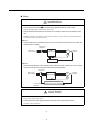
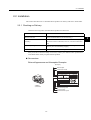
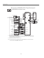
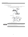
Wiring
WARNING
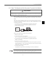
• Connect the ground terminal
to electrical codes (ground resistance: 100 Ω or less).
Improper grounding may result in electric shock or fire.
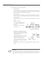
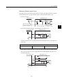
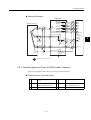
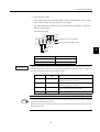
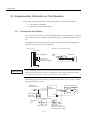
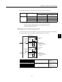
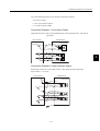
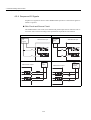
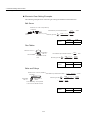
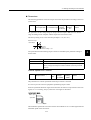
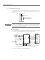
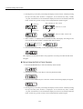
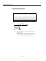
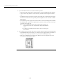
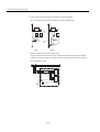
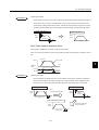
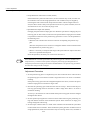
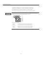
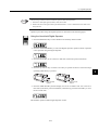
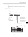
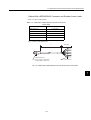
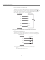
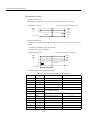
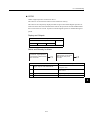
• Use the thermal protector built into the servomotor according to either of the two following methods.
SGMBH servomotors are cooled by a fan. If the fan is defective or power to the fan is disconnected, heat
from the motor may result in burns or fire.
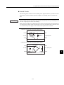
Method 1:
• Wire the output from the thermal protector to the host controller and turn OFF the servo when the
thermal protector operates.
Main circuit
contactors
SGDH
SERVOPACK
Main circuit
power supply
M
Thermal
protector
PG
Servo OFF
Host Controller
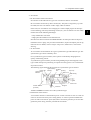
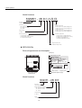
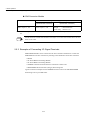
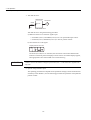
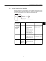
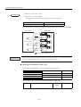
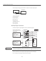
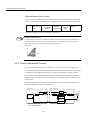
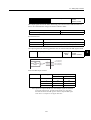
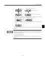
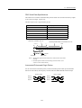
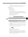
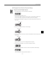
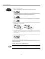
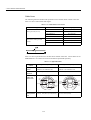
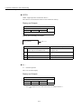
Method 2:
• Wire the thermal protector to the operating circuit of the main circuit contactors or the host controller and turn OFF the main circuit when the thermal protector operates.
Main circuit
contactors
Main circuit
power supply
SGDH
SERVOPACK
M
Thermal
protector
PG
To main circuit
contactors
Host controller or operating
circuit of main circuit contactors
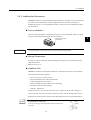
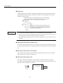
CAUTION
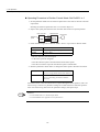
• Do not connect a three-phase power supply to the SERVOPACK’s U, V, or W output terminals.
Doing so may result in injury or fire.
• Securely fasten the power supply terminal screws and motor output terminal screws.
Not doing so may result in fire.
vii
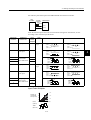
Operation
WARNING
• Never touch any rotating motor parts while the motor is running.
Doing so may result in injury.
CAUTION
• Conduct trial operation on the servomotor alone with the motor shaft disconnected from machine to
avoid any unexpected accidents.
Not doing so may result in injury.
• Before starting operation with a machine connected, change the settings to match the parameters
of the machine.
Starting operation without matching the proper settings may cause the machine to run out of control or malfunction.
• Before starting operation with a machine connected, make sure that an emergency stop can be
applied at any time.
Not doing so may result in injury.
• Do not touch the heat sinks during operation.
Doing so may result in burns due to high temperatures.
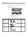
Maintenance and Inspection
WARNING
• Never touch the inside of the SERVOPACKs.
Doing so may result in electric shock.
• Do not remove the panel cover while the power is ON.
Doing so may result in electric shock.
• Do not touch terminals for five minutes after the power is turned OFF.
Residual voltage may cause electric shock.
CAUTION
• Do not disassemble the servomotor.
Doing so may result in electric shock or injury.
• Do not attempt to change wiring while the power is ON.
Doing so may result in electric shock or injury.
viii
General Precautions
Note the following to ensure safe application.
• The drawings presented in this manual are sometimes shown without covers or protective guards. Always
replace the cover or protective guard as specified first, and then operate the products in accordance with
the manual.
• The drawings presented in this manual are typical examples and may not match the product you received.
• This manual is subject to change due to product improvement, specification modification, and manual
improvement. When this manual is revised, the manual code is updated and the new manual is published
as a next edition.
• If the manual must be ordered due to loss or damage, inform your nearest Yaskawa representative or one
of the offices listed on the back of this manual.
• Yaskawa will not take responsibility for the results of unauthorized modifications of this product.
Yaskawa shall not be liable for any damages or troubles resulting from unauthorized modification.
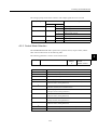
SGDH SERVOPACK Standards and Certification
SGDH SERVOPACKs conform to the following standards. However, because this product is
a built-in type, reconfirmation is required after being installed in the final product.
• EN55011 group 1 class A
• EN50082-2
ix
CONTENTS
1 For First-time Users of AC Servos
1.1 Basic Understanding of AC Servos - - - - - - - - - - - - - - - - - - 1-2
1.1.1 Servo Mechanisms - - - - - - - - - - - - - - - - - - - - - - - - - - - - - - - - - - - - 1-2
1.1.2 Technical Terms- - - - - - - - - - - - - - - - - - - - - - - - - - - - - - - - - - - - - - - 1-4
1.2 Configuration of Servo System - - - - - - - - - - - - - - - - - - - - - 1-5
1.3 Features of Σ-ΙΙ Series Servos - - - - - - - - - - - - - - - - - - - - - 1-10
1.3.1 Outline - - - - - - - - - - - - - - - - - - - - - - - - - - - - - - - - - - - - - - - - - - - - 1-10
1.3.2 Using the SGDH SERVOPACK - - - - - - - - - - - - - - - - - - - - - - - - - - - 1-11
2 Basic Operation
2.1 Precautions - - - - - - - - - - - - - - - - - - - - - - - - - - - - - - - - - - - 2-2
2.2 Installation - - - - - - - - - - - - - - - - - - - - - - - - - - - - - - - - - - - - 2-5
2.2.1 Checking on Delivery - - - - - - - - - - - - - - - - - - - - - - - - - - - - - - - - - - - 2-5
2.2.2 Installing the Servomotor - - - - - - - - - - - - - - - - - - - - - - - - - - - - - - - - 2-7
2.2.3 Allowable Radial and Thrust Loads - - - - - - - - - - - - - - - - - - - - - - - - 2-10
2.2.4 Installing the SERVOPACK - - - - - - - - - - - - - - - - - - - - - - - - - - - - - - 2-11
2.2.5 Power Loss - - - - - - - - - - - - - - - - - - - - - - - - - - - - - - - - - - - - - - - - - 2-13
2.3 Connection and Wiring - - - - - - - - - - - - - - - - - - - - - - - - - - 2-14
2.3.1 Connecting to Peripheral Devices - - - - - - - - - - - - - - - - - - - - - - - - - 2-14
2.3.2 Main Circuit Wiring and Power ON Sequence- - - - - - - - - - - - - - - - - 2-18
2.4 I/O Signals- - - - - - - - - - - - - - - - - - - - - - - - - - - - - - - - - - - 2-21
2.4.1 Examples of I/O Signal Connections - - - - - - - - - - - - - - - - - - - - - - - 2-22
2.4.2 List of CN1 Terminals - - - - - - - - - - - - - - - - - - - - - - - - - - - - - - - - - - 2-23
2.4.3 I/O Signal Names and Functions - - - - - - - - - - - - - - - - - - - - - - - - - - 2-24
2.4.4 Interface Circuits - - - - - - - - - - - - - - - - - - - - - - - - - - - - - - - - - - - - - 2-26
2.5 Wiring Encoders- - - - - - - - - - - - - - - - - - - - - - - - - - - - - - - 2-30
2.5.1 Connecting an Encoder (CN2) and Output Signals
from the SERVOPACK (CN1) - - - - - - - - - - - - - - - - - - - - - - - - - - - - 2-30
2.5.2 Terminal Layout and Types of CN2 Encoder Connector - - - - - - - - - - 2-31
2.5.3 Examples of Connecting I/O Signal Terminals- - - - - - - - - - - - - - - - - 2-32
3 Trial Operation
3.1 Two-step Trial Operation - - - - - - - - - - - - - - - - - - - - - - - - - - 3-2
3.1.1 Step 1: Trial Operation for Servomotor without Load - - - - - - - - - - - - - 3-3
3.1.2 Step 2: Trial Operation with the Servomotor Connected
to the Machine - - - - - - - - - - - - - - - - - - - - - - - - - - - - - - - - 3-9
x
3.2 Supplementary Information on Trial Operation - - - - - - - - - 3-10
3.2.1 Servomotors with Brakes - - - - - - - - - - - - - - - - - - - - - - - - - - - - - - - 3-10
3.2.2 Position Control by Host Controller- - - - - - - - - - - - - - - - - - - - - - - - - 3-11
3.3 Minimum Parameters and Input Signals - - - - - - - - - - - - - - 3-12
3.3.1 Parameters - - - - - - - - - - - - - - - - - - - - - - - - - - - - - - - - - - - - - - - - - 3-12
3.3.2 Input Signals - - - - - - - - - - - - - - - - - - - - - - - - - - - - - - - - - - - - - - - - 3-13
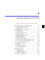
4 Parameter Settings and Functions
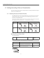
4.1 Settings According to Device Characteristics - - - - - - - - - - - 4-4
4.1.1 Switching Servomotor Rotation Direction - - - - - - - - - - - - - - - - - - - - -4-4
4.1.2 Setting the Overtravel Limit Function - - - - - - - - - - - - - - - - - - - - - - - -4-5
4.1.3 Limiting Torques - - - - - - - - - - - - - - - - - - - - - - - - - - - - - - - - - - - - - - -4-9
4.2 Settings According to Host Controller - - - - - - - - - - - - - - - - 4-14
4.2.1 Speed Reference - - - - - - - - - - - - - - - - - - - - - - - - - - - - - - - - - - - - - 4-14
4.2.2 Position Reference - - - - - - - - - - - - - - - - - - - - - - - - - - - - - - - - - - - - 4-16
4.2.3 Using the Encoder Signal Output - - - - - - - - - - - - - - - - - - - - - - - - - - 4-22
4.2.4 Sequence I/O Signals - - - - - - - - - - - - - - - - - - - - - - - - - - - - - - - - - - 4-26
4.2.5 Using the Electronic Gear Function - - - - - - - - - - - - - - - - - - - - - - - - 4-29
4.2.6 Contact Input Speed Control - - - - - - - - - - - - - - - - - - - - - - - - - - - - - 4-33
4.2.7 Using Torque Control - - - - - - - - - - - - - - - - - - - - - - - - - - - - - - - - - - 4-38
4.2.8 Torque Feed-forward Function - - - - - - - - - - - - - - - - - - - - - - - - - - - - 4-44
4.2.9 Speed Feed-forward Function - - - - - - - - - - - - - - - - - - - - - - - - - - - - 4-46
4.2.10 Torque Limiting by Analog Voltage Reference, Function 1- - - - - - - - 4-47
4.2.11 Torque Limiting by Analog Voltage Reference, Function 2 - - - - - - - - 4-48
4.2.12 Reference Pulse Inhibit Function (INHIBIT) - - - - - - - - - - - - - - - - - - 4-50
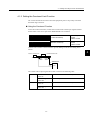
4.3 Setting Up the SERVOPACK - - - - - - - - - - - - - - - - - - - - - - 4-52
4.3.1 Parameters - - - - - - - - - - - - - - - - - - - - - - - - - - - - - - - - - - - - - - - - - 4-52
4.3.2 JOG Speed - - - - - - - - - - - - - - - - - - - - - - - - - - - - - - - - - - - - - - - - - 4-53
4.3.3 Input Circuit Signal Allocation - - - - - - - - - - - - - - - - - - - - - - - - - - - - 4-53
4.3.4 Output Circuit Signal Allocation - - - - - - - - - - - - - - - - - - - - - - - - - - - 4-57
4.3.5 Control Mode Selection - - - - - - - - - - - - - - - - - - - - - - - - - - - - - - - - - 4-59
4.4 Setting Stop Functions - - - - - - - - - - - - - - - - - - - - - - - - - - 4-62
4.4.1 Adjusting Offset - - - - - - - - - - - - - - - - - - - - - - - - - - - - - - - - - - - - - - 4-62
4.4.2 Using the Dynamic Brake - - - - - - - - - - - - - - - - - - - - - - - - - - - - - - - 4-63
4.4.3 Using the Zero Clamp Function - - - - - - - - - - - - - - - - - - - - - - - - - - - 4-64
4.4.4 Using the Holding Brake - - - - - - - - - - - - - - - - - - - - - - - - - - - - - - - - 4-66
4.5 Forming a Protective Sequence - - - - - - - - - - - - - - - - - - - - 4-70
4.5.1 Using Servo Alarm and Alarm Code Outputs- - - - - - - - - - - - - - - - - - 4-70
4.5.2 Using the Servo ON Input Signal - - - - - - - - - - - - - - - - - - - - - - - - - - 4-72
4.5.3 Using the Positioning Completed Output Signal- - - - - - - - - - - - - - - - 4-73
4.5.4 Speed Coincidence Output - - - - - - - - - - - - - - - - - - - - - - - - - - - - - - 4-75
4.5.5 Using the Running Output Signal - - - - - - - - - - - - - - - - - - - - - - - - - - 4-76
xi
4.5.6 Using the Servo Ready Output Signal - - - - - - - - - - - - - - - - - - - - - - 4-77
4.5.7 Using the Warning Output Signal- - - - - - - - - - - - - - - - - - - - - - - - - - 4-78
4.5.8 Using the Near Output Signal - - - - - - - - - - - - - - - - - - - - - - - - - - - - 4-80
4.5.9 Handling Power Loss - - - - - - - - - - - - - - - - - - - - - - - - - - - - - - - - - - 4-81
4.6 External Regenerative Resistors - - - - - - - - - - - - - - - - - - - 4-83
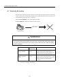
4.7 Absolute Encoders - - - - - - - - - - - - - - - - - - - - - - - - - - - - - 4-84
4.7.1 Interface Circuit - - - - - - - - - - - - - - - - - - - - - - - - - - - - - - - - - - - - - - 4-85
4.7.2 Selecting an Absolute Encoder - - - - - - - - - - - - - - - - - - - - - - - - - - - 4-86
4.7.3 Handling Batteries - - - - - - - - - - - - - - - - - - - - - - - - - - - - - - - - - - - - 4-86
4.7.4 Absolute Encoder Setup - - - - - - - - - - - - - - - - - - - - - - - - - - - - - - - - 4-87
4.7.5 Absolute Encoder Reception Sequence - - - - - - - - - - - - - - - - - - - - - 4-90
4.7.6 Multiturn Limit Setting- - - - - - - - - - - - - - - - - - - - - - - - - - - - - - - - - - 4-95
4.8 Special Wiring - - - - - - - - - - - - - - - - - - - - - - - - - - - - - - - - 4-99
4.8.1 Wiring Precautions- - - - - - - - - - - - - - - - - - - - - - - - - - - - - - - - - - - - 4-99
4.8.2 Wiring for Noise Control - - - - - - - - - - - - - - - - - - - - - - - - - - - - - - - 4-101
4.8.3 Using More Than One Servodrive - - - - - - - - - - - - - - - - - - - - - - - - 4-105
4.8.4 Extending Encoder Cables - - - - - - - - - - - - - - - - - - - - - - - - - - - - - 4-106
5 Servo Adjustment
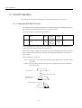
5.1 Smooth Operation - - - - - - - - - - - - - - - - - - - - - - - - - - - - - - 5-2
5.1.1 Using the Soft Start Function- - - - - - - - - - - - - - - - - - - - - - - - - - - - - - 5-2
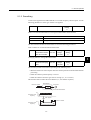
5.1.2 Smoothing- - - - - - - - - - - - - - - - - - - - - - - - - - - - - - - - - - - - - - - - - - - 5-3
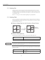
5.1.3 Adjusting Gain - - - - - - - - - - - - - - - - - - - - - - - - - - - - - - - - - - - - - - - - 5-4
5.1.4 Adjusting Offset - - - - - - - - - - - - - - - - - - - - - - - - - - - - - - - - - - - - - - - 5-4
5.1.5 Setting the Torque Reference Filter Time Constant - - - - - - - - - - - - - - 5-5
5.1.6 Notch Filter - - - - - - - - - - - - - - - - - - - - - - - - - - - - - - - - - - - - - - - - - - 5-5
5.2 High-speed Positioning - - - - - - - - - - - - - - - - - - - - - - - - - - - 5-6
5.2.1 Setting Servo Gain- - - - - - - - - - - - - - - - - - - - - - - - - - - - - - - - - - - - - 5-6
5.2.2 Using Feed-forward Control - - - - - - - - - - - - - - - - - - - - - - - - - - - - - - 5-8
5.2.3 Using Proportional Control - - - - - - - - - - - - - - - - - - - - - - - - - - - - - - - 5-8
5.2.4 Setting Speed Bias - - - - - - - - - - - - - - - - - - - - - - - - - - - - - - - - - - - - 5-9
5.2.5 Using Mode Switch - - - - - - - - - - - - - - - - - - - - - - - - - - - - - - - - - - - 5-10
5.2.6 Speed Feedback Compensation - - - - - - - - - - - - - - - - - - - - - - - - - - 5-14
5.3 Autotuning - - - - - - - - - - - - - - - - - - - - - - - - - - - - - - - - - - - 5-16
5.3.1 Online Autotuning - - - - - - - - - - - - - - - - - - - - - - - - - - - - - - - - - - - - 5-17
5.3.2 Machine Rigidity Settings for Online Autotuning - - - - - - - - - - - - - - - 5-19
5.3.3 Saving Results of Online Autotuning - - - - - - - - - - - - - - - - - - - - - - - 5-22
5.3.4 Parameters Related to Online Autotuning- - - - - - - - - - - - - - - - - - - - 5-25
5.4 Servo Gain Adjustments - - - - - - - - - - - - - - - - - - - - - - - - - 5-27
5.4.1 Servo Gain Parameters - - - - - - - - - - - - - - - - - - - - - - - - - - - - - - - - 5-27
5.4.2 Basic Rules of Gain Adjustment - - - - - - - - - - - - - - - - - - - - - - - - - - 5-27
5.4.3 Making Manual Adjustments - - - - - - - - - - - - - - - - - - - - - - - - - - - - - 5-29
xii
5.4.4 Gain Setting Reference Values - - - - - - - - - - - - - - - - - - - - - - - - - - - 5-34
5.5 Analog Monitor- - - - - - - - - - - - - - - - - - - - - - - - - - - - - - - - 5-36
6 Using the Digital Operator
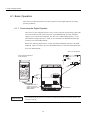
6.1 Basic Operation - - - - - - - - - - - - - - - - - - - - - - - - - - - - - - - - 6-2
6.1.1 Connecting the Digital Operator - - - - - - - - - - - - - - - - - - - - - - - - - - - -6-2
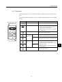
6.1.2 Functions- - - - - - - - - - - - - - - - - - - - - - - - - - - - - - - - - - - - - - - - - - - -6-3
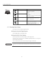
6.1.3 Resetting Servo Alarms- - - - - - - - - - - - - - - - - - - - - - - - - - - - - - - - - -6-4
6.1.4 Basic Mode Selection - - - - - - - - - - - - - - - - - - - - - - - - - - - - - - - - - - -6-5
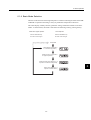
6.1.5 Status Display Mode - - - - - - - - - - - - - - - - - - - - - - - - - - - - - - - - - - - -6-6
6.1.6 Operation in Parameter Setting Mode- - - - - - - - - - - - - - - - - - - - - - - -6-9
6.1.7 Operation in Monitor Mode - - - - - - - - - - - - - - - - - - - - - - - - - - - - - - 6-15
6.2 Applied Operation - - - - - - - - - - - - - - - - - - - - - - - - - - - - - 6-20
6.2.1 Operation in Alarm Traceback Mode- - - - - - - - - - - - - - - - - - - - - - - - 6-21
6.2.2 Controlling Operation Through the Digital Operator - - - - - - - - - - - - - 6-22
6.2.3 Automatic Adjustment of the Speed and Torque Reference Offset- - - 6-25
6.2.4 Manual Adjustment of the Speed and Torque Reference Offset- - - - - 6-28
6.2.5 Clearing Alarm Traceback Data - - - - - - - - - - - - - - - - - - - - - - - - - - - 6-33
6.2.6 Checking the Motor Model- - - - - - - - - - - - - - - - - - - - - - - - - - - - - - - 6-35
6.2.7 Checking the Software Version - - - - - - - - - - - - - - - - - - - - - - - - - - - 6-38
6.2.8 Zero-point Search Mode - - - - - - - - - - - - - - - - - - - - - - - - - - - - - - - - 6-39
6.2.9 Initializing Parameter Settings - - - - - - - - - - - - - - - - - - - - - - - - - - - - 6-42
6.2.10 Manual Zero Adjustment and Gain Adjustment of
Analog Monitor Output - - - - - - - - - - - - - - - - - - - - - - - - - - - - - - - - - 6-44
6.2.11 Adjusting the Motor Current Detection Offset - - - - - - - - - - - - - - - - - 6-49
6.2.12 Password Setting (Write Prohibited Setting) - - - - - - - - - - - - - - - - - 6-53
6.2.13 Clearing Option Unit Detection Results - - - - - - - - - - - - - - - - - - - - - 6-55
7 Servo Selection and Data Sheets
7.1 Selecting a S-II Series Servodrives - - - - - - - - - - - - - - - - - - 7-3
7.1.1 Selecting Servomotors - - - - - - - - - - - - - - - - - - - - - - - - - - - - - - - - - -7-3
7.1.2 Selecting SERVOPACKs - - - - - - - - - - - - - - - - - - - - - - - - - - - - - - - - -7-8
7.2 Servomotor Ratings and Specifications - - - - - - - - - - - - - - - 7-9
7.2.1 Ratings and Specifications - - - - - - - - - - - - - - - - - - - - - - - - - - - - - - -7-9
7.2.2 Mechanical Characteristics - - - - - - - - - - - - - - - - - - - - - - - - - - - - - - 7-11
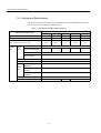
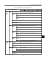
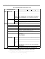
7.3 SERVOPACK Ratings and Specifications - - - - - - - - - - - - 7-13
7.3.1 Combined Specifications - - - - - - - - - - - - - - - - - - - - - - - - - - - - - - - - 7-13
7.3.2 Ratings and Specifications - - - - - - - - - - - - - - - - - - - - - - - - - - - - - - 7-14
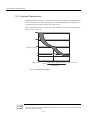
7.3.3 Overload Characteristics - - - - - - - - - - - - - - - - - - - - - - - - - - - - - - - - 7-18
7.3.4 Starting and Stopping Time - - - - - - - - - - - - - - - - - - - - - - - - - - - - - - 7-19
7.3.5 Load Moment of Inertia - - - - - - - - - - - - - - - - - - - - - - - - - - - - - - - - - 7-19
7.3.6 Overhanging Load - - - - - - - - - - - - - - - - - - - - - - - - - - - - - - - - - - - - 7-20
xiii
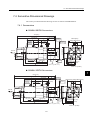
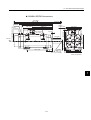
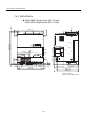
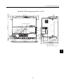
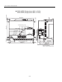
7.4 Servodrive Dimensional Drawings - - - - - - - - - - - - - - - - - - 7-21
7.4.1 Servomotors - - - - - - - - - - - - - - - - - - - - - - - - - - - - - - - - - - - - - - - - 7-21
7.4.2 SERVOPACKs- - - - - - - - - - - - - - - - - - - - - - - - - - - - - - - - - - - - - - - 7-24
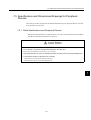
7.5 Specifications and Dimensional Drawings
for Peripheral Devices - - - - - - - - - - - - - - - - - - - - - - - - - - 7-27
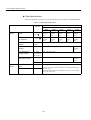
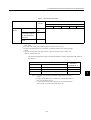
7.5.1 Cable Specifications and Peripheral Devices - - - - - - - - - - - - - - - - - 7-27
7.5.2 Digital Operator - - - - - - - - - - - - - - - - - - - - - - - - - - - - - - - - - - - - - - 7-31
7.5.3 CN1 Connector - - - - - - - - - - - - - - - - - - - - - - - - - - - - - - - - - - - - - - 7-32
7.5.4 Connector Terminal Block Converter Unit - - - - - - - - - - - - - - - - - - - - 7-34
7.5.5 Cable With CN1 Connector and One End Without Connector- - - - - - 7-36
7.5.6 CN2 Encoder Connector at SERVOPACK - - - - - - - - - - - - - - - - - - - 7-37
7.5.7 Encoder Cables - - - - - - - - - - - - - - - - - - - - - - - - - - - - - - - - - - - - - - 7-37
7.5.8 Absolute Encoder Battery - - - - - - - - - - - - - - - - - - - - - - - - - - - - - - - 7-41
7.5.9 Brake Power Supplies - - - - - - - - - - - - - - - - - - - - - - - - - - - - - - - - - 7-42
7.5.10 Molded-case Circuit Breaker (MCCB) - - - - - - - - - - - - - - - - - - - - - 7-44
7.5.11 Noise Filter - - - - - - - - - - - - - - - - - - - - - - - - - - - - - - - - - - - - - - - - 7-44
7.5.12 Surge Suppressor - - - - - - - - - - - - - - - - - - - - - - - - - - - - - - - - - - - 7-46
7.5.13 Regenerative Resistor Unit - - - - - - - - - - - - - - - - - - - - - - - - - - - - - 7-46
7.5.14 Dynamic Brake (DB) Unit - - - - - - - - - - - - - - - - - - - - - - - - - - - - - - 7-50
7.5.15 Thermal Relays - - - - - - - - - - - - - - - - - - - - - - - - - - - - - - - - - - - - - 7-56
7.5.16 Variable Resistor for Speed Setting - - - - - - - - - - - - - - - - - - - - - - - 7-59
7.5.17 Encoder Signal Converter Unit - - - - - - - - - - - - - - - - - - - - - - - - - - 7-59
7.5.18 Cables for Connecting PCs to a SERVOPACK - - - - - - - - - - - - - - - 7-61
8 Inspection, Maintenance, and Troubleshooting
8.1 Servodrive Inspection and Maintenance - - - - - - - - - - - - - - 8-2
8.1.1 Servomotor Inspection - - - - - - - - - - - - - - - - - - - - - - - - - - - - - - - - - - 8-2
8.1.2 SERVOPACK Inspection - - - - - - - - - - - - - - - - - - - - - - - - - - - - - - - - 8-3
8.1.3 Replacing Battery for Absolute Encoder - - - - - - - - - - - - - - - - - - - - - - 8-4
8.2 Troubleshooting - - - - - - - - - - - - - - - - - - - - - - - - - - - - - - - - 8-5
8.2.1 Troubleshooting Problems with Alarm Displays- - - - - - - - - - - - - - - - - 8-5
8.2.2 Troubleshooting Problems with No Alarm Display - - - - - - - - - - - - - - 8-35
8.2.3 Alarm Display Table - - - - - - - - - - - - - - - - - - - - - - - - - - - - - - - - - - 8-37
8.2.4 Warning Displays - - - - - - - - - - - - - - - - - - - - - - - - - - - - - - - - - - - - - 8-39
8.2.5 Internal Connection Diagram and Instrument Connection
Examples - - - - - - - - - - - - - - - - - - - - - - - - - - - - - - - - - - - - - - - - - - 8-40
Appendix A List of Parameters
INDEX
xiv
1
1
For First-time Users of AC Servos
This chapter is intended for first–time users of AC servos. It describes the
basic configuration of a servo mechanism and basic technical terms relating to
servos. Users who already have experience in using a servo should also take a
look at this chapter to understand the features of Σ-ΙΙ Series AC Servos.
1.1 Basic Understanding of AC Servos - - - - - - - - - - - - - - - - - - - 1-2
1.1.1 Servo Mechanisms - - - - - - - - - - - - - - - - - - - - - - - - - - - - - - - - - - - - 1-2
1.1.2 Technical Terms - - - - - - - - - - - - - - - - - - - - - - - - - - - - - - - - - - - - - - - 1-4
1.2 Configuration of Servo System - - - - - - - - - - - - - - - - - - - - - - 1-5
1.3 Features of Σ-ΙΙ Series Servos - - - - - - - - - - - - - - - - - - - - - 1-10
1.3.1 Outline - - - - - - - - - - - - - - - - - - - - - - - - - - - - - - - - - - - - - - - - - - - - 1-10
1.3.2 Using the SGDH SERVOPACK - - - - - - - - - - - - - - - - - - - - - - - - - - - 1-11
1-1
1 For First-time Users of AC Servos
1.1.1 Servo Mechanisms
1.1 Basic Understanding of AC Servos
This section describes the basic configuration of a servo mechanism and technical terms relating
to servos and also explains the features of Σ-ΙΙ Series AC Servos.
1.1.1 Servo Mechanisms
You may be familiar with the following terms:
• Servo
• Servo mechanism1
• Servo control system
In fact, these terms are synonymous. They have the following meaning:
A control mechanism that monitors physical quantities such as specified positions.
In short, a servo mechanism is like a servant who does tasks faithfully and quickly according
to his master’s instructions. In fact, “servo” originally derives from the word “servant.”
Servo system could be defined in more detail as a mechanism that:
• Moves at a specified speed and
• Locates an object in a specified position
1
TERMS
Servo mechanism
According to Japanese Industrial Standard (JIS) terminology, a “servo mechanism” is defined as a
mechanism that uses the position, direction, or orientation of an object as a process variable to control
a system to follow any changes in a target value (set point). More simply, a servo mechanism is a control mechanism that monitors physical quantities such as specified positions. Feedback control is normally performed by a servo mechanism. (Source: JIS B0181)
1-2
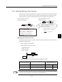
1.1 Basic Understanding of AC Servos
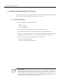
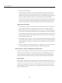
To develop such a servo system, an automatic control system involving feedback control1
must be designed. This automatic control system can be illustrated in the following block
diagram:
Configuration of Servo System
Specified position +
input
-
Servo
amplifier
Servomotor
Controlled
machine
(load)
Machine position
output
Feedback part
Detector
This servo system is an automatic control system that detects the machine position (output
data), feeds back the data to the input side, compares it with the specified position (input
data), and moves the machine by the difference between the compared data.
In other words, the servo system is a system to control the output data to match the specified
input data.
If, for example, the specified position changes, the servo system will reflect the changes.
In the above example, input data is defined as a position, but input data can be any physical
quantities such as orientation (angle), water pressure, or voltage.
Position, speed, force (torque), electric current, and so on are typical controlled values for a
servo system.
1
TERMS
Feedback control
A control method in which process variables are returned to the input side to form a closed loop. It is
also called closed-loop control. If a negative signal is returned to the input side, it is called negative
feedback control. Normally, negative feedback control is used to stabilize the system. If feedback is
not returned, the control method is called open-loop control.
1-3
1
1 For First-time Users of AC Servos
1.1.2 Technical Terms
1.1.2 Technical Terms
The main technical terms used in this manual are as follows:
• Servo mechanism
• Servo
Normally, servo is synonymous with servo mechanism. However, because “mechanism” is omitted, the meaning becomes somewhat ambiguous. Servo may refer to the
entire servo mechanism but may also refer to an integral part of a servo mechanism such
as a servomotor or a servo amplifier. This manual also follows this convention in the use
of the term “servo.”
• Servo control system
Servo control system is almost synonymous with servo mechanism but places the focus
on system control. In this manual, the term “servo system” is also used as a synonym of
servo control system.
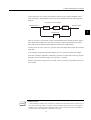
Related Terms
Meaning
Servomotor
General servomotors or Yaskawa SGMBH servomotors. In some cases,
a position detector (encoder) is included in a servomotor.
SERVOPACK
Trademark of Yaskawa servo amplifier “SGDH SERVOPACK.”
Servo drive
A servomotor and amplifier pair. Also called “servo.”
Servo system
A closed control system consisting of a host controller, servo drive and
controlled system to form a servo mechanism.
Host controller
Reference
CN8
POW
ER
O
P
E
R
A
T
O
R
CN3
DATA/
Operate
CN5
SERVOPACK
WARNING
May cause
electric shock.
MODE/ SET
Amplifier
Servomotor
(SERVOPACK)
5
! SGDH-
YASKAW
A
Disconnect all power
and wait 5 min.
before servicing.
Use proper
grounding techniques.
480 460 440 400 380 0 V V V V V V
DC
DUDVDWB1 B2 DC
24N 24P
CHARGE
-
+1
+2
L1/R
L2/S
L3/T
U
V
W
Servo drive
Servo system
1-4
Controlled
system
1.2 Configuration of Servo System
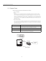
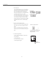
1.2 Configuration of Servo System
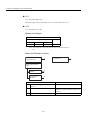
The following diagram illustrates a servo system in detail:
Host controller
(5)
1
Position or
speed
reference
Servo amplifier
Power
Comparator
amplifier
(4)
(Output)
Motor
drive
circuit
(Input)
Position
Speed
(1)
Gear
Position or
speed
feedback
(3)
Detector
(2)
servomotor
Controlled
system
Movable table
Ball screw
Drive system
(1)
Controlled
system:
Mechanical system for which the position or speed is to be controlled. This
includes a drive system that transmits torque from a servomotor.
(2)
Servomotor:
A main actuator that moves a controlled system. Two types are available: AC servomotor and DC servomotor.
(3)
Detector:
A position or speed detector. Normally, an encoder mounted on a motor is used as
a position detector.
(4)
Servo amplifier:
An amplifier that processes an error signal to correct the difference between a reference and feedback data and operates the servomotor accordingly. A servo
amplifier consists of a comparator, which processes error signals, and a power
amplifier, which operates the servomotor.
(5)
Host controller:
A device that controls a servo amplifier by specifying a position or speed as a set
point.
1-5
1 For First-time Users of AC Servos
1.1.2 Technical Terms
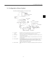
Servo components (1) to (5) are outlined below:
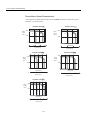
1. Controlled System
In the previous figure, the controlled system is a movable table for which the position or
speed is controlled. The movable table is driven by a ball screw and is connected to the
servomotor via gears. So, the drive system consists of:
• Gears + Ball Screw
This drive system is most commonly used because the power transmission ratio (gear
ratio) can be freely set to ensure high positioning accuracy. However, play in the gears
must be minimized.
The following drive system1 is also possible when the controlled system is a movable
table:
• Coupling + Ball Screw
When the power transmission ratio is
Rolling-contact
guide
1 : 1, a coupling is useful because it
has no play.
Coupling
This drive system is widely used for
Ball screw
Rolling-contact
bearing
machining tools.
Housing
• Timing Belt + Trapezoidal Screw Thread
A timing belt is a coupling device that allows
the power transmission ratio to be set freely
and that has no play.
A trapezoidal screw thread does not provide
Trapezoidal
screw thread
excellent positioning accuracy, so can be
treated as a minor coupling device.
To develop an excellent servo system, it is
important to select a rigid drive system that
Servomotor
Timing belt
has no play.
Configure the controlled system by using an appropriate drive system for the control
purpose.
1
TERMS
Drive system
Also called a drive mechanism. A drive system connects an actuator (such as a servomotor) to a controlled system and serves a mechanical control component that transmits torque to the controlled system, orientates the controlled system, and converts motion from rotation to linear motion and vice
versa.
1-6
1.2 Configuration of Servo System
2. Servomotor
• DC Servomotor and AC Servomotor
Servomotors are divided into two types: DC servomotors and AC servomotors.
DC servomotors are driven by direct current (DC). They have a long history. Up until
the 1980s, the term “servomotor” used to imply a DC servomotor.
From 1984, AC servomotors were emerging as a result of rapid progress in microprocessor technology. Driven by alternating current (AC), AC servomotors are now widely
used because of the following advantages:
• Easy maintenance: No brush
• High speed: No limitation in rectification rate
Note however that servomotors and SERVOPACKs use some parts that are subject to
mechanical wear or aging. For preventive maintenance, inspect and replace parts at regular intervals. For details, refer to Chapter 8 Inspection, Maintenance, and Troubleshooting.
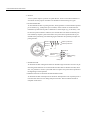
• AC Servomotor
AC servomotors are divided into two types: Synchronous type and induction type. The
synchronous type is more commonly used.
For a synchronous type servomotor, motor speed is controlled by changing the frequency of alternating current.
A synchronous type servomotor provides strong holding torque when stopped, so this
type is ideal when precise positioning is required. Use this type for a servo mechanism
for position control.
The following figure illustrates the structure of a synchronous type servomotor:
Rotary disc
Light-emitting
element
Light-receiving Armature
element
Housing
Front cap
wire
Stator core
Ball bearing
Shaft
Rotor core
Magnet
Position detector
(encoder)
Lead wire
Yaskawa SGMBH servomotors are of the synchronous type.
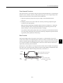
• Performance of Servomotor
A servomotor must have “instantaneous power” so that it can start as soon as a start reference is received. The term “power rating (kW/s)” is used to represent instantaneous
power. It refers to the electric power (kW) that a servomotor generates per second. The
greater the power rating, the more powerful the servomotor.
1-7
1
1 For First-time Users of AC Servos
3. Detector
A servo system requires a position or speed detector. It uses an encoder mounted on a
servomotor for this purpose. Encoders are divided into the following two types:
• Incremental Encoder
An incremental encoder is a pulse generator, which generates a certain number of pulses
per revolution (e.g., 2,000 pulses per revolution). If this encoder is connected to the
mechanical system and one pulse is defined as a certain length (e.g., 0.001 mm), it can
be used as a position detector. However, this encoder does not detect an absolute position and merely outputs a pulse train. Hence zero point return operation must be performed before positioning. The following figure illustrates the operation principle of a
pulse generator:
Phase A pulse train
Phase A
Phase B
Phase B pulse train
Phase Z
Slit
Center of
revolution
Fixed slit
Rotary
disc
Light-emitting
element
Light-receiving
element
Rotary slit
• Absolute Encoder
An absolute encoder is designed to detect an absolute angle of rotation as well as to perform the general functions of an incremental encoder. With an absolute encoder, therefore, it is possible to create a system that does not require zero point return operation at
the beginning of each operation.
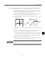
• Difference between an Absolute and Incremental Encoder
An absolute encoder will keep track of the motor shaft position even if system power is
lost and some motion occurs during that period of time. The incremental encoder is
incapable of the above.
1-8
1.2 Configuration of Servo System
4. Servo Amplifier
A servo amplifier is required to operate an AC servomotor. The following figure illustrates the configuration of a servo amplifier:
Servo amplifier
Power
Comparator amplifier
Motor driving AC power
Reference
input
1
Feedback
Servomotor
Commercial AC power
A servo amplifier consists of the following two sections:
• Comparator
A comparator consists of a comparison function and a control function. The comparison
function compares reference input (position or speed) with a feedback signal and generates a differential signal.
The control function amplifies and transforms the differential signal. In other words, it
performs proportional (P) control or proportional/integral (PI) control1. (It is not important if you do not understand these control terms completely at this point.)
• Power Amplifier
A power amplifier runs the servomotor at a speed or torque proportional to the output of
the comparator. In other words, from the commercial power supply of 50/60 Hz, it generates alternating current with a frequency proportional to the reference speed and runs
the servomotor with this current.
5. Host Controller
A host controller controls a servo amplifier by specifying a position or speed as a set
point.
For speed reference, a position control loop may be formed in the host controller when a
position feedback signal is received. Yaskawa machine controller MP920 is a typical
host controller.
1
TERMS
Proportional/integral (PI) control
PI control provides more accurate position or speed control than proportional control, which is more
commonly used.
1-9
1 For First-time Users of AC Servos
1.3.1 Outline
1.3 Features of Σ-ΙΙ Series Servos
A Σ-ΙΙ Series Servo consists of an SGMBH servomotor and an SGDH SERVOPACK.
1.3.1 Outline
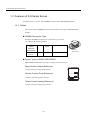
This section outlines SGMBH servomotor types and the control types of SGDH SERVOPACKs.
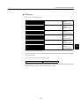
SGMBH Servomotor Type
Σ-ΙΙ Series SGMBH servomotors are synchronous type servomotors and have the following features:
Rated Motor
Speed
Maximum
Motor Speed
-1
1500 min
Voltage
Maximum
Torque
400 V
200 %
Rated Output
SGMBH
Servomotor
22 to 55 kW (10 models)
-1
2000 min
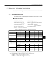
Control Types of SGDH SERVOPACK
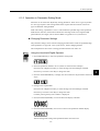
SGDH SERVOPACKs allow the control of speed, position and torque.
Speed Control (Analog Reference)
Accepts an analog voltage speed reference.
Position Control (Pulse Reference)
WARNING
5
May cause
electric shock.
Disconnect all power
and wait 5 min.
before servicing.
Accepts a pulse train position reference.
Torque Control (Analog Reference)
Accepts an analog voltage torque reference.
1-10
Use proper
grounding techniques.
SGDH SERVOPACK
1.3 Features of Σ-ΙΙ Series Servos
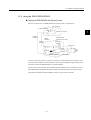
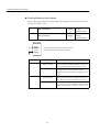
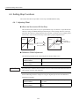
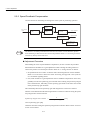
1.3.2 Using the SGDH SERVOPACK
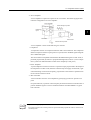
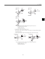
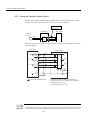
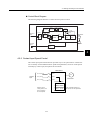
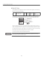
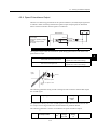
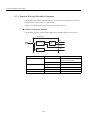
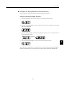
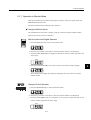
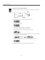
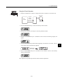
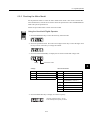
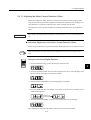
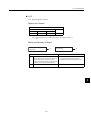
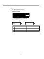
Using the SERVOPACK for Speed Control
The most common use of a SERVOPACK for speed control is shown below:
Host controller
Position reference+
-
Position
feedback
1
Position control loop
SERVOPACK
(speed control mode)
Speed
reference
(Analog
voltage)
Power
amplifier
Servomotor
+
+
Position
Speed
Convert
Pulse train
Torque
(current)
feedback
Position feedback
Encoder
As shown in the above figure, a position control loop is formed in the host controller. The
host controller compares a position reference with a position feedback signal and sends the
processed result to the SERVOPACK as a speed reference.
In this way the host controller can be freed from performing the servo mechanism control.
The SERVOPACK undertakes the speed control loop and subsequent control processing.
The Yaskawa machine controller MP920 is used as a typical host controller.
1-11
1 For First-time Users of AC Servos
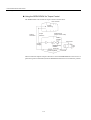
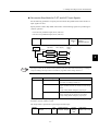
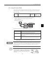
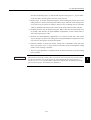
1.3.2 Using the SGDH SERVOPACK
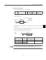
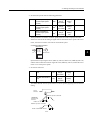
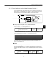
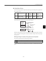
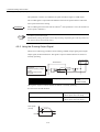
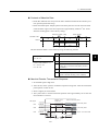
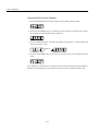
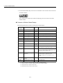
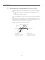
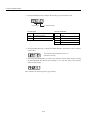
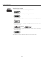
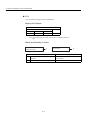
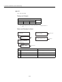
Using the SERVOPACK for Torque Control
The SERVOPACK can be used for torque control as shown below.
Host controller
Position
monitoring
Position
information
Torque
reference
SERVOPACK
(torque control mode)
Power
amplifier
Servomotor
(Analog
voltage)
Torque (current)
feedback
Pulse train
Position feedback
Encoder
The host controller outputs a torque reference to control the SERVOPACK. It also receives a
pulse train (position information) from the SERVOPACK and uses it to monitor the position.
1-12
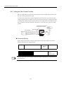
1.3 Features of Σ-ΙΙ Series Servos
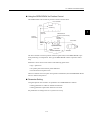
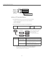
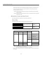
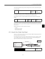
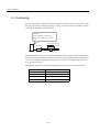
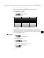
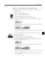
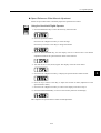
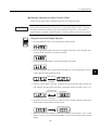
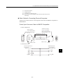
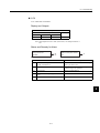
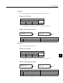
Using the SERVOPACK for Position Control
The SERVOPACK can be used for position control as shown below.
Host controller
Position
monitoring
1
Position
reference
SERVOPACK
(position control mode)
Position
information
Power
amplifier
+
+
-
Pulse
train
Servomotor
-
Speed/current loop
Pulse train
Position feedback
Encoder
The host controller can send a position reference (pulse train) to the SERVOPACK to perform positioning or interpolation. This type of SERVOPACK contains a position control
loop.
Parameters can be used to select either of the following pulse trains:
• Sign + pulse train
• Two-phase pulse train with 90° phase difference
• Forward and reverse pulse trains
The host controller receives a pulse train (position information) from the SERVOPACK and
uses it to monitor the position.
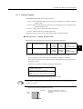
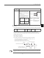
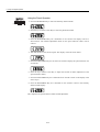
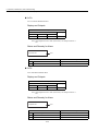
Parameter Setting
A Digital Operator can be used to set parameters for a SERVOPACK as follows:
• Setting parameters to enable or disable each function
• Setting parameters required for functions to be used
Set parameters according to the servo system to be set up.
1-13
2
Basic Operation
This chapter describes the first things to do when Σ-II Series products are
delivered. It also explains the most fundamental ways of connecting and operating Σ-II Series products. Both first-time and experienced servo users must
read this chapter.
2.1 Precautions - - - - - - - - - - - - - - - - - - - - - - - - - - - - - - - - - - - 2-2
2.2 Installation - - - - - - - - - - - - - - - - - - - - - - - - - - - - - - - - - - - - 2-5
2.2.1 Checking on Delivery - - - - - - - - - - - - - - - - - - - - - - - - - - - - - - - - - - - 2-5
2.2.2 Installing the Servomotor - - - - - - - - - - - - - - - - - - - - - - - - - - - - - - - - 2-7
2.2.3 Allowable Radial and Thrust Loads - - - - - - - - - - - - - - - - - - - - - - - - 2-10
2.2.4 Installing the SERVOPACK - - - - - - - - - - - - - - - - - - - - - - - - - - - - - - 2-11
2.2.5 Power Loss - - - - - - - - - - - - - - - - - - - - - - - - - - - - - - - - - - - - - - - - - 2-13
2.3 Connection and Wiring - - - - - - - - - - - - - - - - - - - - - - - - - - 2-14
2.3.1 Connecting to Peripheral Devices - - - - - - - - - - - - - - - - - - - - - - - - - 2-14
2.3.2 Main Circuit Wiring and Power ON Sequence - - - - - - - - - - - - - - - - - 2-18
2.4 I/O Signals - - - - - - - - - - - - - - - - - - - - - - - - - - - - - - - - - - - 2-21
2.4.1 Examples of I/O Signal Connections - - - - - - - - - - - - - - - - - - - - - - 2.4.2 List of CN1 Terminals - - - - - - - - - - - - - - - - - - - - - - - - - - - - - - - - - 2.4.3 I/O Signal Names and Functions - - - - - - - - - - - - - - - - - - - - - - - - - 2.4.4 Interface Circuits - - - - - - - - - - - - - - - - - - - - - - - - - - - - - - - - - - - - -
2-22
2-23
2-24
2-26
2.5 Wiring Encoders - - - - - - - - - - - - - - - - - - - - - - - - - - - - - - - 2-30
2.5.1Connecting an Encoder (CN2) and Output Signals
from the SERVOPACK (CN1) - - - - - - - - - - - - - - - - - - - - - - - - - - - - 2-30
2.5.2 Terminal Layout and Types of CN2 Encoder Connector - - - - - - - - - - 2-31
2.5.3 Examples of Connecting I/O Signal Terminals - - - - - - - - - - - - - - - - 2-32
2-1
2
2 Basic Operation
2.1 Precautions
This section provides notes on using Σ-II Series products.
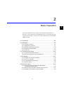
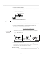
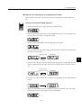
Use a 400-VAC power supply.
Use a 400-VAC power supply.
Do not connect the servomotor directly to a commercial power line.
Direct connection to the power frequency sup-
Direct
connection
ply will damage the servomotor. The servomotor cannot be operated without an SGDH
400 VAC
power supply
SERVOPACK.
Damage will result!
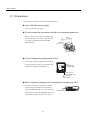
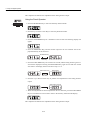
Do not change wiring when power is ON.
Always turn the power OFF before connecting
or disconnecting a connector. (Except for Digital Operator (Model: JUSP-OP02A-2))
CN8
POW
ER
O
P
E
R
A
T
O
R
CN3
WARNING
MODE/ SET
DATA/
CN5
OFF
(POWER and
CHANGE lamp)
SERVOPACK
5
!
SGDH-
May cause
electric shock.
YASKAW
A
Disconnect all power
and wait 5 min.
before servicing.
Use proper
grounding techniques.
480 460 440 400 380 0
V V V V V V
DC
DUDVDWB1 B2 DC
24N 24P
CHARGE
-
+1
+2
L1/R
L2/S
L3/T
U
V
W
Always turn the
power OFF before
connecting a
connector.
Before inspecting, always wait 5 minutes after turning power OFF.
Even after the power is turned OFF, residual
electric charge still remains in the capacitor
inside the SERVOPACK. To prevent an electric
shock, always wait for the CHARGE lamp to go
OFF before starting inspection (if necessary).
2-2
CHARGE lamp
2.1 Precautions
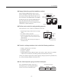
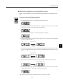
Always follow the specified installation method.
When installing SERVOPACKs side by side as
Provide sufficient clearance
shown in the figure on the right, allow at least 10
480 460 440 400 380 0
V V V V V V
10 mm
or more
DC
DUDVDWB1 B2 DC
24N 24P
CHARGE
mm (0.39 in) between and at least 50 mm (1.97 in)
-
above and below each SERVOPACK. The SERVO-
+1
L1/R
+2
L2/S
L3/T
U
V
W
50 mm
or more
PACK generates heat. Install the SERVOPACK so
CN8
POW
ER
that it can radiate heat freely. Note also that the
O
P
E
R
A
T
O
R
CN3
SERVOPACK must be in an environment free from
WARNING
MODE/ SET
DATA/
SERVOPACK
5
!
YASKAW
A
Disconnect all power
and wait 5 min.
before servicing.
WARNING
Use proper
grounding techniques.
MODE/ SET
DATA/
CN5
SERVOPACK
5
!
SGDH-
May cause
electric shock.
CN8
POW
ER
O
P
E
R
A
T
O
R
CN3
CN5
SGDH-
May cause
electric shock.
YASKAW
A
Disconnect all power
and wait 5 min.
before servicing.
Use proper
grounding techniques.
480 460 440 400 380 0
V V V V V V
DC
DUDVDWB1 B2 DC
24N 24P
480 460 440 400 380 0
V V V V V V
CHARGE
DC
DUDVDWB1 B2 DC
24N 24P
CHARGE
condensation, vibration and shock.
-
+1
+2
L1/R
L2/S
L3/T
U
V
W
-
+1
+2
L1/R
L2/S
L3/T
U
V
W
Ambient temperature: 0 to 55°C
2
Perform noise reduction and grounding properly.
If the signal line is noisy, vibration or malfunction will result.
• Separate high-voltage cables from low-voltage
cables.
Casing
SERVOPACK
Single
line
• Use cables as short as possible.
• Perform the grounding with the ground resistance of 100 Ω or less for the servomotor and
SERVOPACK.
Servomotor
M
Ground
(with resistance
of 100 Ω or less)
• Never use a line filter for the power supply in
the motor circuit.
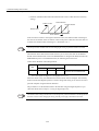
Conduct a voltage resistance test under the following conditions.
• Voltage: 1500 Vrms AC, one minute
• Current limit: 100 mA
• Frequency: 50/60 Hz
• Voltage application points: Between 480 V, 460 V, 440 V, 400 V, 380 V, 0 V terminals,
L1/R, L2/S, L3/T terminals, and frame ground (connect terminals securely).
Contact your Yaskawa representative before applying voltage to points not specified above,
e.g., when performing standards certification tests.
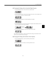
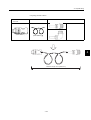
Use a fast-response type ground-fault interrupter.
For a ground-fault interrupter, always use a
fast-response type or one designed for PWM
inverters. Do not use a time-delay type.
2-3
Ground-fault interrupter
GOOD
GOOD
POOR
Fast-response
type
For PWM
inverter
Time-delay
type
2 Basic Operation
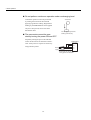
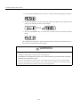
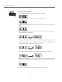
Do not perform continuous operation under overhanging load.
Continuous operation cannot be performed
Servomotor
by rotating the motor from the load and
applying regenerative braking. Regenerative
braking by the SERVOPACK can be applied
only for a short period, such as the motor
deceleration time.
The servomotor cannot be operated by turning the power ON and OFF.
Do not apply regenerative
braking continuously.
Frequently turning the power ON and OFF
causes the internal circuit elements to deteri-
SERVOPACK
orate. Always start or stop the servomotor by
380 to 480 V
0V
using reference pulses.
L1/R
Power
supply
L2/S
L3/T
Do not start or stop by
tuning power ON and OFF.
2-4
2.2 Installation
2.2 Installation
This section describes how to check Σ-II Series products on delivery and how to install them.
2.2.1 Checking on Delivery
Check the following items when Σ-II Series products are delivered.
Check Items
Comments
Are the delivered products the ones
that were ordered?
Check the model numbers marked on the nameplates of the servomotor and SERVOPACK. (See the following.)
Does the servomotor shaft rotate
smoothly?
The servomotor shaft is normal if it can be turned smoothly by
hand. Servomotors with brakes, however, cannot be turned manually.
Is there any damage?
Check the overall appearance, and check for damage or scratches
that may have occurred during shipping.
Are there any loose screws?
Check screws for looseness using a screwdriver.
If any of the above items are faulty or incorrect, contact your Yaskawa sales representative
or the dealer from whom you purchased the products.
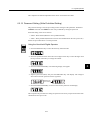
Servomotors
External Appearance and Nameplate Examples
(Example)
Rated output
Servomotor model
AC SERVO MOTOR
SGMBH - 2BDCA
N. m
22
140
TYPE
kw
min -1
1500 A
CONT.
58
ENCODER
UTMAH- B12BDYR11
17 bit
RATING
K7A500 101 - 004
9708
YASKAWA ELECTRIC CORPORATION
SER.NO.
DATE
JAPAN
SGMBH
servomotor
Munufacturing date
Serial number
Rated rotation speed
2-5
2
2 Basic Operation
2.2.1 Checking on Delivery
Model Numbers
SGMBH - 2B D C A
Σ-II Series
Servomotor
Options
1: With V-type oil seal
B: With V-type oil seal, 90-VDC holding brake
C: With V-type oil seal, 24-VDC holding brake
S: With S-type oil seal
D: With S-type oil seal, 90-VDC holding brake
E: With S-type oil seal, 24-VDC holding brake
Servomotor Capacity
2B: 22 kW 4E: 45 kW
3Z: 30 kW 5E: 55 kW
3G: 37 kW
Supply Voltage
D: 400 V
Encoder Specifications
Shaft End Specifications
2: 17-bit absolute encoder
3: 20-bit absolute encoder (optional)
C: 17-bit incremental encoder
2: Flange mounted, straight without key
6: Flange mounted, straight with key and tap
K: With foot, straight without key
L: With foot, straight with key and tap
Design Revision Order
A: Maximum torque 200%
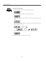
SERVOPACKs
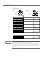
External Appearance and Nameplate
(Example)
SERVOPACK model
SERVOPACK
CN8
POW
ER
O
P
E
R
A
T
O
R
CN3
WARNING
MODEL
SGDH - 3ZDE
AC - INPUT
AC - OUTPUT
VOLTS 380 - 480 VOLTS 0 - 480
Hz
50/60
PHASE 3
PHASE 3
AMPS 175
kW (HP) 30.0 (40.2)
AMPS 145
S / N R7C303 - 221 - 4
MODE/ SET
DATA/
CN5
YASKAWA ELECTRIC
SERVOPACK
5
!
MADE IN JAPAN
SGDH-
May cause
electric shock.
YASKAW
A
Disconnect all power
and wait 5 min.
before servicing.
Use proper
grounding techniques.
480 460 440 400 380 0
V V V V V V
DC
DUDVDWB1 B2 DC
24N 24P
CHARGE
-
+1
+2
L1/R
L2/S
L3/T
U
V
W
Serial number
Σ-II Series SGDH
SERVOPACK
Output power
Applicable power supply
Model Numbers
SGDH - 2B D E
Σ-II Series
SGDH SERVOPACK
Rated Output (motor capacity)
2B: 22 kW 4E: 45 kW
3Z: 30 kW 5E:: 55 kW
3G: 37 kW
Supply Voltage
D: 400 V
Model
E: For speed/torque control and position control
2-6
2.2 Installation
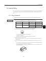
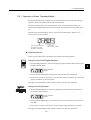
2.2.2 Installing the Servomotor
SGMBH servomotors can be installed either horizontally or vertically. The service life of the
servomotor will be shortened or unexpected problems will occur if the servomotor is
installed incorrectly or in an inappropriate location. Always observe the following installation instructions.
Prior to Installation
The end of the motor shaft is coated with anticorrosive paint. Thoroughly remove the paint
using a cloth moistened with thinner prior to installation.
2
Anticorrosive paint is
coated here.
Avoid getting thinner on other parts of the servomotor when cleaning the shaft.
IMPORTANT
Storage Temperature
Store the servomotor within the following temperature range if it is stored with the power
cable disconnected.
Between -20 to 60 °C.
Installation Site
SGMBH servomotors are designed for indoor use. Install the servomotor in environments
that satisfy the following conditions.
• Free of corrosive or explosive gases.
• Well-ventilated and free of dust and moisture.
• Ambient temperature of 0 to 40 °C.
• Relative humidity of 20% to 80% (non-condensing)
• Facilitates inspection and cleaning.
• Altitude : 1000 m max.
Install a protective cover over the servomotor if it is used in a location that is subject to
water or oil mist. Also use a servomotor with an oil seal to seal the through shaft1 section.
Install the electrical connector with the cable facing downward or in a horizontal position.
TERMS
1
Through Sections of the shaft
This refers to the gap where the shaft protrudes from the end of
the motor.
2-7
Shaft
opening
2 Basic Operation
2.2.2 Installing the Servomotor
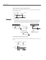
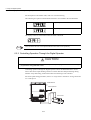
Alignment
Align the shaft of the servomotor with that of the equipment to be controlled, then connect
the shafts with flexible couplings. Install the servomotor so that alignment accuracy falls
within the following range.
Measure this distance at four different positions in the circumference.
The difference between the maximum and minimum measurements
must be 0.03 mm or less. (Turn together with couplings)
Measure this distance at four different positions in the
circumference. The difference between the maximum
and minimum measurementsmust be 0.03 mm or less.
(Turn together with couplings)
IMPORTANT
1. Vibration that will damage the bearings will occur if the shafts are not properly aligned.
2. Do not allow direct impact to be applied to the shafts when installing the coupling. Otherwise the
encoder mounted on the opposite end of the shaft may be damaged.
3. Before mounting the pinion gear directly to the motor output shaft, consult your Yaskawa sales representative.
Wiring the Servomotor Power Lines
Connect the servomotor power lines (U, V, and W) to the servomotor terminal block (M10)
in the servomotor terminal box. Connect the ground wire to the ground screw in the terminal
box.
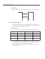
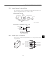
Wiring the Servomotor Thermostat
The servomotor has a built-in thermostat. Wire the thermostat leads (l, lb) to the terminal
block (M4) in the servomotor’s terminal box.
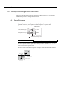
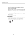
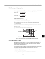
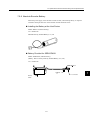
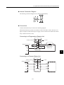
Wiring the Servomotor Fan
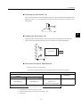
Wire the servomotor fan leads U(A), V(B), and W(C) so that the direction of air flows
according to the following diagram. If the air flows in the opposite direction, change the wiring of any of the two phases U, V, and W.
Servomotor
Direction of
cool air
2-8
2.2 Installation
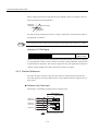
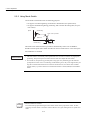
Protecting the Servomotor Fan
The servomotor fan has a built-in thermal protector, as shown in the following diagram, that
operates at 140°C ±5 %. To protect the servomotor fan from overcurrent, use with a 2-A nofuse breaker.
U
V
W
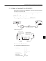
2
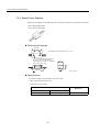
Installing the Servomotor Fan
To maximize the cooling capacity of the servomotor fan, install the fan at least 200 mm
(7.87 in) from the inlet side of the servomotor as shown in the following diagram.
Cool air
Servomotor
200 mm min.
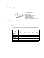
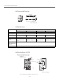
Servomotor Connector Specifications
• Encoder Connector at Servomotor
The connector specifications for the encoder on the servomotor are as follows:
Encoder Connectors
Plug
L-shaped
Straight
JA08A-20-29S-JA-EB *2, *3
or
MS3108B20-29S
JA06A-20-29S-J1-EB *2, *3
or
MS3106B20-29S
Cable Clamp
Receptacle
JL04-2022CKE (**) *2, *3
or
MS3057-12A
** indicates the cable diameter.
97F-3102E20-29P
To be prepared by the customer
* 1. Connector at servomotor is already provided.
* 2. Manufactured by Japan Aviation Electronics Industry, Ltd.
* 3. Waterproof.
2-9
*1
*3
2 Basic Operation
2.2.3 Allowable Radial and Thrust Loads
• Fan Connector on Servomotor
The connector specifications for the fan on the servomotor are as follows:
Fan Connectors
Plug
Cable Clamp
L-shaped
Straight
CE05-8A18-10SD-B-BAS *2, *3
CE05-6A18-10SD-B-BSS *2, *3
or
MS3106B18-10S
or
MS3108B18-10S
Receptacle
CE3057-10A-* (D265) *2, *3
or
MS3057-10A
** indicates the cable diameter.
*1
CE05-2A18-10PD-B *3
To be prepared by the customer
* 1. Connector at servomotor is already provided.
* 2. Manufactured by Daiichi Denshi Kogyo Co., Ltd.
* 3. Waterproof.
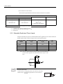
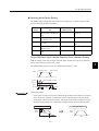
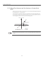
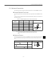
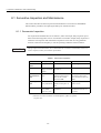
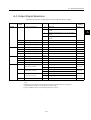
2.2.3 Allowable Radial and Thrust Loads
Design the mechanical system so radial and thrust loads1 applied to the servomotor shaft end
during operation falls within the ranges shown in the following table.
Servomotor Model
SGMBH-
Allowable Radial Load
Fr [N]
Allowable Thrust Load
Fs [N]
LR
[mm]
2BD
5880
2156
100
3ZD
6272
2156
100
3GD
7448
2156
100
4ED
7840
2156
100
5ED
8428
2156
110
Note: Allowable radial and thrust loads shown above are the maximum values that could be applied to the shaft end from motor torque or other
loads.
LR
Fr
Fs
TERMS
1
Radial and thrust loads
Thrust load (Fs): Load applied parallel to the centerline of the shaft.
Radial load (Fr): Load applied perpendicular to the centerline of
the shaft.
Fr
Motor
2-10
Fs
2.2 Installation
2.2.4 Installing the SERVOPACK
The SGDH SERVOPACK is a base-mounting servo controller. Incorrect installation will
cause problems. Always observe the installation instructions below.
Storage Temperature
Store the servomotor within the following temperature range if it
is stored with the power cable disconnected.
Between -20 to +85 °C.
WARNING
5
May cause
electric shock.
Disconnect all power
and wait 5 min.
before servicing.
Use proper
grounding techniques.
2
SGDH SERVOPACK
Installation Site
Take the following precautions at the installation site.
Situation
Notes on Installation
Installation in a Control Panel
Design the control panel size, unit layout, and cooling method
so the temperature around the SERVOPACK does not exceed
55°C.
Installation Near a Heating Unit
Minimize heat radiated from the heating unit as well as any temperature rise caused by natural convection so the temperature
around the SERVOPACK does not exceed 55°C.
Installation Near a Source of Vibration
Install a vibration isolator beneath the SERVOPACK to avoid
subjecting it to vibration.
Installation at a Site Exposed to Corrosive Gas
Take appropriate action to avoid corrosive gas. Corrosive gas
does not have an immediate effect on the SERVOPACK, but
will eventually cause electronic components and contactorrelated devices to malfunction.
Other Situations
Do not install the SERVOPACK in hot and humid locations or
locations subject to excessive dust or iron powder in the air.
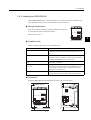
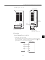
Orientation
120 mm min.
Install the SERVOPACK perpendicular to the wall as shown in the figure.
50 mm min.
(ventilation exhaust)
CN8
POW
ER
O
P
E
R
A
T
O
R
CN3
WARNING
Air flow
MODE/ SET
DATA/
CN5
SERVOPACK
5
!
SGDH-
May cause
electric shock.
YASKAW
A
Disconnect all power
and wait 5 min.
before servicing.
Use proper
grounding techniques.
480 460 440 400 380 0
V V V V V V
DC
DUDVDWB1 B2 DC
24N 24P
CHARGE
+1
+2
L1/R
L2/S
L3/T
U
V
W
50 mm min.
50 mm min.
50 mm min. (ventilation intake)
2-11
120 mm min.
-
Air flow
2 Basic Operation
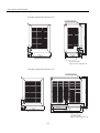
2.2.4 Installing the SERVOPACK
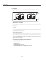
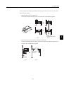
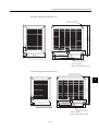
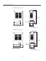
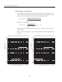
Installation
Follow the procedure below to install multiple SERVOPACKs side by side in a control
panel.
Fan
Fan
WARNING
WARNING
WARNING
WARNING
5
5
May cause
electric shock.
50 mm
or more
5
5
May cause
electric shock.
May cause
electric shock.
May cause
electric shock.
Disconnect all power
and wait 5 min.
before servicing.
Disconnect all power
and wait 5 min.
before servicing.
Disconnect all power
and wait 5 min.
before servicing.
Disconnect all power
and wait 5 min.
before servicing.
Use proper
grounding techniques.
Use proper
grounding techniques.
Use proper
grounding techniques.
Use proper
grounding techniques.
30 mm or more
10 mm or more
50 mm
or more
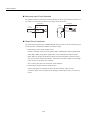
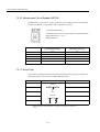
SERVOPACK Orientation
Install the SERVOPACK perpendicular to the wall so the front panel containing connectors
faces outward.
Cooling
As shown in the figure above, allow sufficient space around each SERVOPACK for cooling
by cooling fans or natural convection.
Side-by-side Installation
When installing SERVOPACKs side by side as shown above, allow at least 10mm (0.39 in)
between and at least 50mm (1.97 in) above and below each SERVOPACK. Install cooling
fans above the SERVOPACKs to avoid excessive temperature rise and to maintain even temperature inside the control panel.
Environmental Conditions in the Control Panel
• Ambient Temperature: 0 to 55 °C
• Humidity: 90% RH or less
• Vibration: 4.9 m/s2
• Condensation and Freezing: None
• Ambient Temperature for Long-term Reliability: 45°C max.
2-12
2.2 Installation
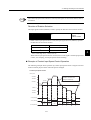
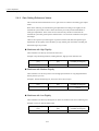
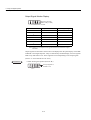
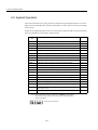
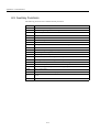
2.2.5 Power Loss
Power loss of SERVOPACK is given below:
SERVOPACK
Model
SGDH-
Output Current
(Effective Value)
[A]
Main Circuit
Power Loss
[W]
Control Circuit
Power Loss
[W]
Total Power Loss
[W]
2BDE
60
650
120
770
3ZDE
88
970
1090
3GDE
105
1140
1260
4EDE
135
1440
1560
5EDE
160
1720
1840
2-13
2
2 Basic Operation
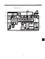
2.3.1 Connecting to Peripheral Devices
2.3 Connection and Wiring
This section describes how to connect Σ-II Series products to peripheral devices and explains a
typical example of wiring the main circuit. It also describes an example of connecting to main
host controllers.
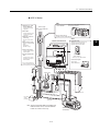
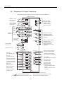
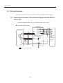
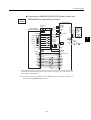
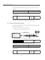
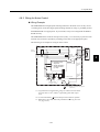
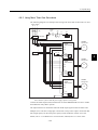
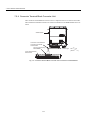
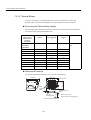
2.3.1 Connecting to Peripheral Devices
This section shows a standard example of connecting Σ-II Series products to peripheral
devices and briefly explains how to connect to each peripheral device.
2-14
2.3 Connection and Wiring
400 V Series
CN1
Host controller
cMolded-case circuit
breaker (MCCB)
Connect the SGDH SERVOPACK to a
Yaskawa host controller.
Power supply
Three-phase 400 VAC
Used to protect power
supply line.
R S T
dNoise filter
Used to eliminate external noise from power
supply line.
c
MP910, MP920, MP930,
and MP-SG1 with a Motion Module
eMagnetic contactor *
(HI Series)
CN3
Turns the servo ON or
OFF.
SGDH SERVOPACK
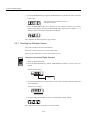
fBrake power supply
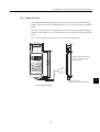
Digital Operator
Allows the user to set parameters or
operation reference and display
operation status or alarm status.
Used for servomotor with
brake.
LPSE-2H01
(for 200 V input)
gPower transformer
Used to switch between
200 V to 400 V.
CN8
POW
ER
hDynamic Brake (DB)
Unit
d
CN3
O
P
E
R
A
T
O
R
CN3
MODE/ SET
DATA/
Hand-held type
(JUSP-OP02A-2)
CN5
Used if dynamic brake
function is required for
SERVOPACK.
1-meter (3.3-ft.) cable included
Personal computer
SERVOPACK
SGDH-
YASKAW
A CN2
Cable model:
JZSP-CMS01 to 03
CN1
* Use a surge suppressor
for themagnetic contactor.
480 460 440 400 380 0
V V V V V V
DC
DUDVDWB1 B2 DC
24N 24P
CHARGE
g
DU DV DW DBON DB24
380 to 480 V
0V
U V W
e
e
L1 L2 L3
B1 B2
DC24P
DC24N
f
DU DV DW
h
Regenerative
Resistor
Brake power supply
DC power
supply
(24 VDC)
Dynamic Brake Unit
+
-
Power supply for
cooling fan
Note: The Dynamic Brake (DB) Unt's DBON and
DB24 terminals can be used with SERVOPACKs of 37 kW or more only.
2-15
DB24
DBON
SGMBH
servomotor
2
2 Basic Operation
2.3.1 Connecting to Peripheral Devices
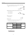
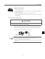
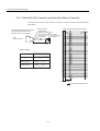
Connector terminal block converter unit (Model: JUSP-TA50P)
The terminal block allows connection to a host controller.
CN1
0.5 meter cable with
CN1 connector
Cable with CN1 connector and one end without connector
1m (3.3ft): JZSP-CKI01-1
2m (6.6ft): JZSP-CKI01-2
CN1
3m (9.8ft): JZSP-CKI01-3
CN1 connector kit
Model: JZSP-CKI9
CN1
Cable for PG
This cable is used to connect the encoder of servomotor to the SERVOPACK.
The following cables are available according to encoder types.
• Cable only (without connector at either end)
Cable Type
Cable Model
Standard Encoder Cable
50-m Specifications Encoder
Cable
Length
Remarks
JZSP-CMP09-05
5 m (196.85 in)
JZSP-CMP09-10
10 m (393.70 in)
JZSP-CMP09-15
15 m (590.55 in)
The maximum allowable cable length is
20 m.
JZSP-CMP09-20
20 m (787.40 in)
JZSP-CMP19-30
30 m (1181.10 in)
JZSP-CMP19-40
40 m (1574.80 in)
JZSP-CMP19-50
50 m (1968.50 in)
Cable
L
2-16
The maximum allowable cable length is
50 m.
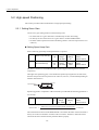
2.3 Connection and Wiring
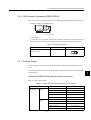
• Cable with a single connector (without connector on encoder end)
Cable Model
Length
JZSP-CMP03-03
3 m (118.11 in)
JZSP-CMP03-05
5 m (196.85 in)
JZSP-CMP03-10
10 m (393.70 in)
JZSP-CMP03-15
15 m (590.55 in)
JZSP-CMP03-20
20 m (787.40 in)
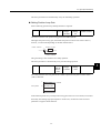
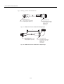
• Cable with connectors on both ends (straight plug on encoder end)
Applicable Servomotors
SGMBH
Servomotors
With Straight
Plug
With L-Shape
Plug
Cable Model
2
Length
JZSP-CMP01-03
3 m (118.11 in)
JZSP-CMP01-05
5 m (196.85 in)
JZSP-CMP01-10
10 m (393.70 in)
JZSP-CMP01-15
15 m (590.55 in)
JZSP-CMP01-20
20 m (787.40 in)
JZSP-CMP02-03
3 m (118.11 in)
JZSP-CMP02-05
5 m (196.85 in)
JZSP-CMP02-10
10 m (393.70 in)
JZSP-CMP02-15
15 m (590.55 in)
JZSP-CMP02-20
20 m (787.40 in)
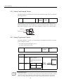
Connector for PG
Connector on
SERVOPACK End Only
55102-0600
(Manufactured by Molex
Japan Co., Ltd.)
Connector on
Servomotor End Only
54280-0600
(Manufactured by Molex
Japan Co., Ltd.)
2-17
Connector kit: JZSP-CMP9-1
-
2 Basic Operation
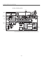
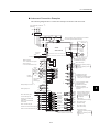
2.3.2 Main Circuit Wiring and Power ON Sequence
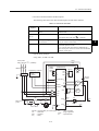
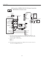
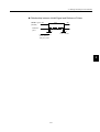
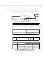
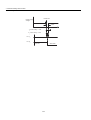
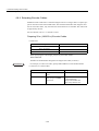
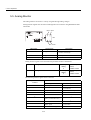
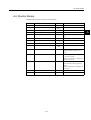
2.3.2 Main Circuit Wiring and Power ON Sequence
This section shows typical examples of main circuit wiring for Σ-II Series servo products,
functions of main circuit terminals, and the power ON sequence.
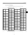
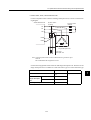
400-V Power Supply
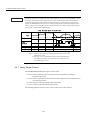
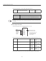
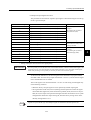
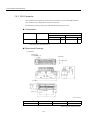
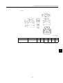
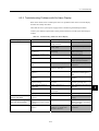
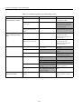
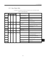
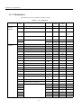
• SERVOPACK Main Circuit Terminal Names and Descriptions
The following table shows the name and description of each main circuit terminal.
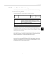
Table 2.1 SERVOPACK Main Circuit Terminals
Terminal
Symbol
Functions
Description
L1/R, L2/S,
L3/T
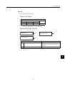
Main power input terminals
Three-phase 380 to 480 VAC , 50/60 Hz
U, V, W
Servomotor connection
terminal
Used to connect to the servomotor.
DC24P,
DC24N
Control power input terminal 24 VDC±15 %
(Two)
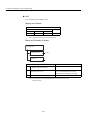
Ground terminal
Connected to ground.
(For power ground and motor ground)
+1, +2
DC reactor connection termi- Used to protect against harmonics
(factory setting: short-circuited)
nal
B1, B2
Regenerative Resistor Unit
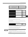
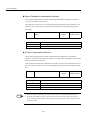
connection terminal
Used to connect the regenerative resistor.
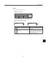
480 V, 460 V,
440 V, 400 V,
380 V, 0 V
Input terminals for control
actuator
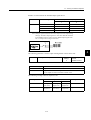
Single-phase 380 to 480 V, 50/60 Hz
Power supply input terminals for the fan and the contactor.
−
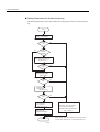
Main circuit minus terminal
Normally, external connection is not required.
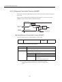
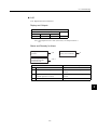
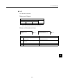
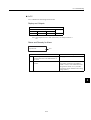
DU, DV, DW
Dynamic Brake Unit
connection terminal
Used to connect the Dynamic Brake Unit.
DBON, DB24
Dynamic Brake Unit connec- Used to connect the Dynamic Brake Unit to the DBON
tion terminal
and DB24 terminals (when using 37-kW and 55-kW
SERVOPACKs only).
2-18
2.3 Connection and Wiring
• Servomotor Terminal Names and Descriptions
The following table shows the name and description of each motor terminal.
Table 2.2 Servomotor Terminals
Terminal
Symbol
Functions
Description
U, V, W
SERVOPACK connection terminals
Used to connect to the U, V, and W terminals of the
SERVOPACK
U (A), V (B),
W (C)
Fan terminals
Used to connect the fan power supply.
A, B
Brake power supply connection terminals
Used to connect the brake power supply (only when
using servomotors with brakes).
1, 1b
Thermal protector terminals
Used to detect overheating of the servomotor and open
the thermal protector circuit.
Use a sequence that turns OFF the SERVOPACK’s
main circuit power or the servomotor when the thermal
protector circuit opens.
Three-phase 380 to 480 VAC , 50/60 Hz
• Typical Wiring Example
Using 400 V, 22 kW or 30 kW
W(C)
Three-phase
% (50/60Hz)
380 to 480 VAC +10
-15
R
S
V(B)
T
U(A)
Regenerative
Resistor
Unit
1MCCB
FIL
Prepared by customer
Control power
supply
DC24V
−
SERVOPACK
SGDH- DE
B1
DB Unit
Fan
DU
DV
DW
B2
+
380 to 480 V
U
0V
V
DC24P FG
DC24N
1MC
U
V
W
W
CN2
L1/R
1
M
Thermal
protector
1b
PG
L2/S
L3/T
1Ry
Main circuit
power
OFF
ON
(Alarm lamp)
1PL
1Ry
CN1
31
ALM -
32
1Ry
+24V
1MC
FG
1MC
ALM+
1D
1SUP
1MCCB : Circuit breaker (for inverter type)
: Noise filter
FIL
: Contactor
1MC
: Relay
1Ry
2-19
1PL
1SUP
1D
: Lamp for display
: Surge suppressor
: Flywheel diode
0 24V
2
2 Basic Operation
2.3.2 Main Circuit Wiring and Power ON Sequence
Using 400 V, 37 kW or 55 kW
W(C)
Three-phase
%
380 to 480 VAC +10
-15
R
S
V(B)
T
U(A)
SERVOPACK
SGDH- DE
1MCCB
FIL
Prepared by customer
Control power
supply
DC24V
−
B1
B2
DB Unit
Fan
DU
DV
DW
DB24
DB0N
380 to 480 VU
+
0V
DC24P FG
DC24N
1MC
U
V
W
V
W
CN2
Thermal
protector
1
M
1b
PG
L1/R
L2/S
L3/T
1Ry
Main circuit
power
OFF
ON
(Alarm lamp)
1PL
1Ry
CN1
31
ALM -
32
1Ry
+24V
1MC
FG
1MC
ALM+
1D
0 24V
1SUP
1MCCB : Circuit breaker (for inverter type)
: Noise filter
FIL
: Contactor
1MC
: Relay
1Ry
1PL
1SUP
1D
: Lamp for display
: Surge suppressor
: Flywheel diode
Note
• Do not bundle or run power and signal lines together in the same duct. Keep power and
signal lines separated by at least 30 cm (11.81 in).
• Use twisted-pair wires or multi-core shielded-pair wires for signal and encoder (PG)
feedback lines. The length for wiring is 3 m (118.11 in) maximum for the reference
input line.
• Do not touch the power terminal even if power was turned OFF. High voltage may still
remain in SERVOPACK. Make sure the charge indicator is out first before starting an
inspection.
• Avoid frequently turning power ON and OFF. Since the SGDH SERVOPACK has a
capacitor in the power supply, a high charging current flows for 0.2 seconds when
power is turned ON. Therefore, frequently turning the power ON and OFF causes the
main circuit devices (such as capacitors and fuses) to deteriorate, resulting in unexpected problems.
2-20
2.4 I/O Signals
2.4 I/O Signals
This section describes I/O signals for the SGDH SERVOPACK.
2
2-21
2 Basic Operation
2.4.1 Examples of I/O Signal Connections
2.4.1 Examples of I/O Signal Connections
The following diagram shows a typical example of I/O signal connections.
SGDH SERVOPACK
∗1.
Reference speed
±2 to ±10 V/rated
motor speed
Torque reference
±1 to ±10 V/rated
motor torque
PULS
Open-collector
reference
power supply
+
+5V
0V
+
+24V
P control
(P control when ON)
Reverse run prohibited
(Prohibited when OFF)
Forward run prohibited
(Prohibited when OFF)
Alarm reset
(Reset when ON)
Reverse current limit
(Limit when ON)
Forward current limit
(Limit when ON)
T -REF
9
SG
10
/SIGN
CLR
Servo ON
(Servo ON when ON)
6
SIGN
CCW
Phase B
SEN signal input ∗3.
SG
/PULS
SIGN
Backup battery
2.8 to 4.5 V ∗3.
5
PULS
CW
Phase A
Position
reference
V -REF
-
∗2.
LPF
∗2.
A/D
LPF
7 150 Ω
37
ALO1
38
ALO2
39
ALO3
Alarm code output
Maximum operating
voltage: 30 VDC
Maximum operating
current: 20 mA DC
Photocouplers
8
11 150 Ω
33
PAO
34
/PAO
12
CLR
15 150 Ω
/CLR
14
PL1
3
PL2
13
PL3
18
BAT (+)
21
BAT (- )
22
SEN
4
SG
2
+24VIN
47
/S-ON
40
/P-CON
41
1kΩ
+12V
∗4.
35
PBO
36
/PBO
19
PCO
20
/PCO
48
PSO
49
/PSO
1
Photocouplers
25
SG
PG dividing ratio output
Applicable line receiver
SN75175 or MC3486
manufactured by T/I or the
equivalent
Amount of phase-S rotation ∗4.
Serial data output
Applicable line receiver
SN75175 or MC3486
manufactured by T/I or the
equivalent
26
/V-CMP+
(/COIN+)
/V-CMP-(/COIN-- )
27
/TGON+
N-OT
43
28
29
/TGON-/S-RDY+
P-OT
42
30
31
/S-RDY-ALM+
32
ALM -
/ALM-RST
/N-CL
/P-CL
44
Speed coincidence detection
(On when speed coincides)
Positioning completed (ON
when positioning is completed)
TGON output
(ON at levels above the setting)
Servo ready output
(ON when ready)
Servo alarm output
(OFF for an alarm)
Photocoupler output
Maximum operating voltage:
30 VDC
Maximum operating current:
50 mA DC
46
45
Connector shell
FG
∗ 1.
represents twisted-pair wires.
∗ 2. The time constant for the primary filter is 47 µs.
2-22
Connect shield to connector shell.
∗ 3. Connector when using an absolute encoder.
∗ 4. Used only with an absolute encoder.
2.4 I/O Signals
2.4.2 List of CN1 Terminals
The following diagram shows the layout and specifications of CN1 terminals.
CN1 Terminal Layout
1
2
SG
6
SEN
SG
27 /TGON+
SEN signal
input
5
/PULS
10 SG
Reference
pulse input
9
14
/SIGN
/CLR
Reference sign
input
13
PULS
T-REF
SIGN
PL2
Clear input
15
16 −
V-REF
GND
11
12
PL1
GND
7
8
CLR
20
22
PL3
/PCO
BAT (-)
29 /S-RDY+
Speed Reference Input
31 ALM+
Reference
pulse input
33 PAO
Torque Reference Input
35
Reference sign
input
Open-collector reference
power supply
37
Open-collector reference
power supply
PG divided
output phase C
PBO
ALO1
39 ALO3
Clear input
41
P-CON
−
43 N-OT
19
21
PCO
BAT (+)
PG divided
output phase C
45 /P-CL
Battery (+)
47
Battery (-)
23 −
24 −
Open-collector reference
power supply
−
17 −
18
GND
GND
3
4
SG
−
49
−
25
/V-CMP+
(/COIN+)
Speed coincidence detection output
TGON signal
output
Servo ready
output
Servo alarm
output
PG divided output phase A
PG divided output phase B
Alarm code
outputs
(open-collector
output)
P operation
input
Reverse overtravel input
Forward current limit ON
input
+24V
-IN
External input
power supply
/PSO
Phase-S signal
output
26 /V-CMP(/COIN-)
Speed
Coincidence
Detection Output
28 /TGON-
TGON signal
output
30 /S-RDY-
Servo ready
output
32 ALM-
Servo alarm
output
34 /PAO
PG divided
output phase
A
36
/PBO
PG divided
output phase B
38
ALO2
Alarm code
outputs
40
/S-ON
Servo ON
input
42
P-OT
Forward overtravel input
44
/ALMRST
Alarm reset
input
46 /N-CL
Reverse current limit ON
input
48
Phase-S signal output
PSO
50 −
Note: 1. Do not use unused terminals for relays.
2. Connect the shield of the I/O signal cable to the connector shell. Connect to the FG (frame
ground) at the SERVOPACK-end connector.
2-23
−
2
2 Basic Operation
2.4.3 I/O Signal Names and Functions
CN1 Specifications
Specifications for SERVOPACK Connectors
10250-52A2JL or
Equivalent 50-p Right
Angle Plug
Applicable Receptacles
Solder Type
Case
10150-3000VE
10350-52A0-008
Manufacturer
Sumitomo 3M Co.
2.4.3 I/O Signal Names and Functions
The following section describes SERVOPACK I/O signal names and functions
Input Signals
Table 2.3 Input Signal Names and Functions
Single Name
Common
Pin
No.
Functions
Reference
/S-ON
40
Servo ON:
Turns ON the servomotor when the gate block in the inverter is released.
/P-CON
41
* Function selected via parameter.
4.5.2
−
Proportional operation reference
Switches the speed control loop from PI (proportional/ integral)
to P (proportional) control when ON.
4.2.1
Direction reference
With internal reference speed selected: Switches the direction of
rotation.
4.2.6
Control mode switching
Position ↔ speed
Control ↔ torque
Torque ↔ speed
4.2.7
Enables control mode switching.
Zero-clamp reference
Speed control with zero-clamp function: Reference speed is
zero when ON.
4.4.3
Reference pulse block
Position control with reference pulse stop: Stops reference pulse
input when ON.
4.2.12
Overtravel prohibited: Stops servomotor when movable part
travels beyond the allowable range of motion.
4.1.2
P-OT
N-OT
42
43
Forward Run prohibited
Reverse Run prohibited
/P-CL
/N-CL
45
46
* Function selected via parameter.
−
Forward current limit ON
Reverse current limit ON
Current limit function used when ON.
4.1.3
Internal speed switching
With internal reference speed selected: Switches the internal
speed settings.
4.2.6
/ALM RST
44
Alarm reset: Releases the servo alarm state.
4.5.1
+24VIN
47
Control power supply input for sequence signals: Users must provide the +24-V power supply. Allowable voltage fluctuation range: 11 to 25 V
4.2.4
Initial data request signal when using an absolute encoder.
4.7.1
Connecting pin for the absolute encoder backup battery.
4.7.1
SEN
BAT (+)
BAT (-)
4 (2)
21
22
2-24
2.4 I/O Signals
Table 2.3 Input Signal Names and Functions (cont’d)
Single Name
Pin
No.
Functions
Reference
Speed
V-REF
5 (6)
Speed reference speed input: ±2 to ±10 V/rated motor speed (Input gain can be modified
using a parameter.)
4.2.1
Torque
T-REF
9
(10)
Torque reference input: ±1 to ±10 V/rated motor torque (Input gain can be modified using a
parameter.)
4.2.7
Position
Reference
PULS
/PULS
SIGN
/SIGN
7
8
11
12
Reference pulse input
Line-driver
Open-collector
4.2.2
CLR
/CLR
15
14
Error counter clear: Clears the error counter during position control.
4.2.2
PL1
PL2
PL3
3
13
18
+12-V pull-up power supply when PULS, SIGN and CLR reference signals are open-collector outputs (+12-V power supply is built into the SERVOPACK).
4.2.2
Input mode
• Sign + pulse train
• CCW/CW pulse
• Two-phase pulse (90° phase
differential)
Note: 1. The functions allocated to /S-ON, /P-CON. P-OT, N-OT, /ALM-RST, /P-CL, and /N-CL
input signals can be changed via parameters. Refer to 4.3.3 Input Circuit Signal Allocation.
2. Pin numbers in parenthesis () indicate signal grounds.
3. The voltage input range for speed and torque references is a maximum of ±12 V.
Output Signals
Table 2.4 Output Signal Names and Functions
Signal Name
Common
Speed
Pin No.
Functions
Reference
ALM+
ALM-
31
32
Servo alarm: Turns OFF when an error is detected.
4.5.1
/TGON+
/TGON-
27
28
Detection during servomotor rotation: Detects whether the servomotor is rotating at a
speed higher than the motor speed setting. Motor speed detection can be set via parameter.
4.5.5
/S-RDY+
/S-RDY-
29
30
Servo ready: ON if there is no servo alarm when the control/main circuit power supply
is turned ON.
4.5.6
PAO
/PAO
PBO
/PBO
PCO
/PCO
33 (1)
34
35
36
19
20
Phase-A signal
Phase-B signal
Phase-C signal
Converted two-phase pulse (phase A and B) encoder output
signal and origin pulse (phase C) signal: RS-422 or the equivalent
4.2.3
PSO
/PSO
48
49
Phase-S signal
With an absolute encoder: Outputs serial data corresponding to
the number of revolutions (RS-422 or equivalent)
4.7.5
ALO1
ALO2
ALO3
37
38
39 (1)
Alarm code output: Outputs 3-bit alarm codes.
Open-collector: 30 V and 20 mA rating maximum
FG
Shell
Connected to frame ground if the shield wire of the I/O signal cable is connected to the
connector shell.
−
25
26
Speed coincidence (output in Speed Control Mode): Detects whether the motor speed
is within the setting range and if it matches the reference speed value.
4.5.4
/V-CMP+
/V-CMP-
2-25
4.5.1
2
2 Basic Operation
2.4.4 Interface Circuits
Table 2.4 Output Signal Names and Functions (cont’d)
Signal Name
Position
Not
used.
/COIN+
/COIN-
Pin No.
Functions
Reference
25
26
Positioning completed (output in Position Control Mode): Turns ON when the number
of error pulses reaches the value set. The setting is the number of error pulses set in reference units (input pulse units defined by the electronic gear).
4.5.3
16
17
23
24
50
These terminals are not used.
Do not connect relays to these terminals.
-
Note: 1. Pin numbers in parenthesis () indicate signal grounds.
2. The functions allocated to /TGON, /S-RDY, and /V-CMP (/COIN) output signals can be
changed via parameters. /CLT, /VCT, /BK, /WARN, and /NEAR signals can also be
changed. Refer to 4.3.4 Output Circuit Signal Allocation.
2.4.4 Interface Circuits
This section shows examples of SERVOPACK I/O signal connection to the host controller.
Interface for Reference Input Circuits
Analog Input Circuit
Analog signals are either speed or torque reference signals at the impedance below.
• Reference speed input: About 14 kΩ
• Reference torque input: About 14 kΩ
The maximum allowable voltages for input signals is ±12 V.
SERVOPACK
1.8kΩ (1/2W) min.
3
12V
25HP-10B
2kΩ
2
1
1000: 1
V-REF or
T-REF
About 14kΩ
SG
0V
2-26
2.4 I/O Signals
Reference Position Input Circuit
An output circuit for the reference pulse and error counter clear signal at the host controller
can be either line-driver or open-collector outputs. These are shown below by type.
• Line-driver Output
SERVOPACK end
Host controller end
150 Ω
Applicable line-driver
SN75174 manufactured
by T/I or the equivalent
4.7kΩ
2 .8 V ≤ (H level) − (L level) ≤ 3 .7 V
• Open-collector Output, Example 1: Power Supply Provided by User
Host controller end
SERVOPACK end
Vcc
R1
i
150 Ω
4.7 kΩ
VF
Tr1
VF = 1.5 to 1.8 V
Use the examples below to set pull-up resistor R1 so the input current, i, falls between 7
and 15 mA.
Application Examples
When Vcc is 24 V ± 5 %:
R1 = 2.2 kΩ
When Vcc is 12 V ± 5 %:
R1 = 1 kΩ
When Vcc is 5 V ± 5 %:
R1 = 180 Ω
• Open-collector Output, Example 2: Using 12-V Power Supply Built into SERVOPACK
This circuit uses the 12-V power supply built into the SERVOPACK. The input is not
insulated in this case.
Host controller end
SERVOPACK end
PL1,PL2,PL3, terminals
1.0 kΩ
+12V
150 Ω
About
9 mA
1.5V max.
when ON
2-27
0V
2
2 Basic Operation
2.4.4 Interface Circuits
Sequence Input Circuit Interface
The sequence input circuit interface connects through a relay or open-collector transistor circuit. Select a low-current relay otherwise a faulty contact will result.
Servoamp
Servoamp
24 VDC
50 mA min.
+24VIN
24 VDC
50 mA min.
3.3 kΩ
+24VIN
3.3 kΩ
/S-ON, etc.
/S-ON, etc.
Output Circuit Interfaces
Any of the following three types of SERVOPACK output circuits can be used. Form an input
circuit at the host controller that matches one of these types.
• Connecting to a Line-driver Output Circuit
Encoder serial data converted to two-phase (phase A and B) pulse output signals (PAO,
/PAO, PBO, /PBO), origin pulse signals (PCO, /PCO) and phase-S rotation signals
(PSO, /PSO) are output via line-driver output circuits that normally comprise the position control system at the host controller. Connect the line-driver output circuit through
a line receiver circuit at the host controller.
See 2.5 Wiring Encoders for connection circuit examples.
• Connecting to an Open-collector Output Circuit
Alarm code signals are output from open-collector transistor output circuits.
Connect an open-collector output circuit through a photocoupler, relay or line receiver
circuit.
2-28
2.4 I/O Signals
SERVOPACK
end
5 to 12 VDC
Photocoupler
SERVOPACK
end
5 to 12 VDC
Relay
0V
0V
0V
SERVOPACK
end
2
5 to 12 VDC
0V
0V
Note: The maximum allowable voltage and current capacities for open-collector output circuits are as follows.
• Voltage: 30 VDC max.
• Current: 20 mA DC max.
• Connecting to a Photocoupler Output Circuit
Photocoupler output circuits are used for servo alarm, servo ready, and other sequence
output signal circuits.
Connect a photocoupler output circuit through a relay or line receiver circuit.
SERVOPACK end
5 to 24 VDC
SERVOPACK end
Relay
5 to 12 VDC
0V
0V
Note: The maximum allowable voltage and current capacities for photocoupler output circuits are as follows.
• Voltage: 30 VDC max.
• Current: 50 mA DC max.
2-29
2 Basic Operation
2.5.1 Connecting an Encoder (CN2) and Output Signals from the SERVOPACK (CN1)
2.5 Wiring Encoders
The following sections describe the procedure for wiring a SERVOPACK to the encoder.
2.5.1 Connecting an Encoder (CN2) and Output Signals from the SERVOPACK (CN1)
The following diagrams show wiring for incremental and absolute encoders.
Incremental Encoders
SERVOPACK
Phase A
Incremental encoder
∗
C (5)
D (6)
CN2
2-5
2-6
Blue
White/Blue
1-33
1-34
PAO
/PAO
Phase B
1-35
1-36
PBO
/PBO
Phase C
1-19
1-20
PCO
/PCO
Output line-driver
SN75ALS194 manufactured
by T/I or the eqivalent
2-1
PG5V
2-2
PG0V
PG
H (1)
Red
G (2) Black
0V
0.33mm 2
(0.001in 2)
1-1 SG
Applicable line
receiver
SN75175
manufactured
by T/I or the
equivalent
0V
Connector shell
J
(Shell)
∗
CN1
Shield wires
Connector
shell
(Customer end)
∗
: represents twisted-pair wires.
2-30
2.5 Wiring Encoders
Absolute Encoders
SERVOPACK
∗
CN1
Phase A
1-33
1-34
PAO
/PAO
Phase B
1-35
1-36
PBO
/PBO
Phase C
1-19
1-20
PCO
/PCO
Phase S
1-48
1-49
Output line-driver
SN75ALS194 manufactured
by T/I or the eqivalent
2-1
PG5V
2-2
PG0V
PSO
/PSO
Absolute encoder
∗
C 5
D 6
CN2
2-5
2-6
Blue
White/Blue
PG
H 1
Red
G 2 Black
0.33mm 2
(0.001in 2)
1-4
SEN
1-2
1-1
SG
SG
Applicable line
receiver
SN75175
manufactured
by T/I or the
equivalent
+5 V
0V
0V
T 3
S 4
Orange
White/
orange
+
Battery
-
Connector shell
J
(Shell)
1-21 BAT +
1-22 BAT -
2-3
2-4
Connector
shell
Shield
(Customer end)
∗
: represents twisted-pair wires.
2.5.2 Terminal Layout and Types of CN2 Encoder Connector
The following diagram shows the layout and types of CN2 terminals.
CN2 Connector Terminal Layout
1
PG5V
PG power supply
+5 V
2
PG 0 V
PG power supply
0V
3
BAT (+)
Battery (+)
4
BAT (-)
Battery (-)
5
PS
6
/PS
(For an absolute encoder)
PG serial signal input
2-31
(For an absolute encoder)
PG serial signal input
2
2 Basic Operation
2.5.3 Examples of Connecting I/O Signal Terminals
CN2 Connector Models
SERVOPACK Connectors
Applicable Plug (or Socket)
Soldered Relay Plug
(SERVOPACK Connector)
53460-0611
Molex Japan Co., Ltd.
55100-0600
Molex Japan Co., Ltd.
Soldered Relay Plug
(Servomotor Connector)
L-shaped plug: MS3108B20-29S or
Straight
: MS3106B20-29S
Cable clamp : MS3057-12A
Note: FA1394 is the product number for the SERVOPACK-end plug set from Molex Japan Co.,
Ltd.
INFO
Encoder cables are available from Yaskawa. See Chapter 7 Servo Selection and Data Sheets for more
details on the cables.
2.5.3 Examples of Connecting I/O Signal Terminals
SGDH SERVOPACKs can be connected to the host controllers listed below. Connect the
SERVOPACK to the host controller by referring to documentation for the host controller.
• MP920
• GL-Series B2833 Positioning Module
• GL-Series B2813 Positioning Module
• OMRON C500-NC222 and C500-NC112 Position Control Units
• MITSUBISHI AD72 and AD71 (B Type) Positioning Unit
Typical connection examples for the OMRON Position Control Unit and MITSUBISHI
Positioning Unit are provided below.
2-32
2.5 Wiring Encoders
Connection to OMRON C500-NC222 Position Control Unit
SERVOPACK for Speed/Torque Control
SERVOPACK
SGDH- DE
Speed/Torque
I/O power
supply
C500-NC222
+24V +
(Made by OMRON) X-axis (Y-axis)
+24V
CCWLX
EXT IN
8
9
2(12)
STPX
3(13)
ORGX
4(14)
EMGX
5(15)
CWLX
3Ry
1
DC GND
11
+24V
0 24V
1Ry
U
V
W
A
B
C
D
380 to 480 V
(ON when
positioning
is stopped)
31
CN1
ALM+
32
ALM-
CN1
P-OT
42
N-OT
43
M/D
3(19)
9(28)
8(24)
47
40
5(9)
6(10)
X-A
X-/A
X-B
X-/B
X-C
X-/C
0V
7(23)
6(22)
5(21)
4(20)
16(14)
15(13)
1(17)
33
34
35
36
19
20
1
50
+24VIN
/S-ON
V-REF(T-REF)
SG
PAO
/PAO
/PBO
PBO
PCO
/PCO
SG
FG
* These signals are output for approximately two seconds when the power is turned ON. Take this
into consideration when designing a power ON sequence. Relay 1Ry is used to stop main circuit
power supply to SERVOPACK.
Note: The signals shown here are applicable only to OMRON C500-NC222 Position Control Unit
and Yaskawa SGDH-DE SERVOPACK.
2-33
2
3Ry
4Ry
OUT-1X
X-OUT
X-AG
M
PG
0V
(ON when
proximity is
detected)
6(16)
DC GND
DC24P
DC24N
L1/R
L2/S
L3/T
0 24V
4Ry
2 Basic Operation
2.5.3 Examples of Connecting I/O Signal Terminals
Connection to OMRON C500-NC112 Position Control Unit
SERVOPACK for Position Control
Position
SERVOPACK
SGDH- DE*2
I/O power
supply
+12V
+
-
L1/R
L2/S
L3/T
0 12V
C500-NC112
(Made by OMRON)
+12V
380 to 480 V
1B
2A
4Ry
CCW limit
2B
3Ry
Emergency stop
3A
External interrupt
3B
Direction output
CW
LRX-01/A2
4B
8
5A
5B
+5V
Pulse output
CW+CCW
6
4A
Ready
M
8A
8B
9A
9B
10A
10B
10
19
9
20
7
1Ry
+5V
+24V
1Ry *1
1
31
32
7
8
11
12
15
14
External power
supply
CN1
0V
(ON when proximity is detected)
Home position
proximity
Local
A
B
C
D
PG
1A
CW limit
Home position
U
V
W
DC24P
DC24N
47
/S-ON
40
P-OT
42
3Ry
N-OT
43
4Ry
+24V
CN1
PCO
/PCO
SG
ALM+
ALM-
PULSE
SIGN
CLR
* 1. These signals are output for approximately two seconds when the power is turned ON. Take
this into consideration when designing a power ON sequence. Relay 1Ry is used to stop main
circuit power supply to SERVOPACK.
* 2. Change the Pn200.0 = 1 setting as follows:
Bit No.3 = 1
Bit No.4 = 0
Bit No.5 = 0
Note: The signals shown here are applicable only to OMRON C500-NC112 Position Control Unit
and Yaskawa SGDH-DE SERVOPACK.
2-34
+24V
2.5 Wiring Encoders
Connection to MITSUBISHI AD72 Positioning Unit
SERVOPACK for Speed/Torque Control
Speed/Torque
SERVOPACK
SGDH- DE
DC24P
DC24N
I/O power supply
+24V
+24V +AD72
(Made by MITSUBISHI)
STOP
DOG
0 24V
READY
(ON when
positioning
is stopped)
CONT
1
2
3
4
5
6
0V
0V
ENCO
4
5
7
8
10
11
3
6
0V
9
PULSE A
PULSE B
PULSE C
U
V
W
A
B
(ON when
proximity is
detected)
380 to 480 V
0V
47
40
CN1
+24VIN
/S-ON
31
ALM+
1Ry *1
1Ry
32
5(9)
6(10)
ALMV-REF (T-REF)
PG
CN1
P-OT
42
N-OT
43
SG
35
PBO
36
33
/PBO
PAO
34
19
/PAO
PCO
20
1
/PCO
SG
50
FG
* 1. These signals are output for approximately two seconds when the power is turned ON. Take
this into consideration when designing a power ON sequence. Relay 1Ry is used to stop main
circuit power supply to SERVOPACK.
* 2. These pin numbers are the same for both X and Y axes.
Note: The signals shown here are applicable only to MITSUBISHI AD72 Positioning Unit and
Yaskawa SGDH-DE SERVOPACK.
2-35
M
C
D
*2
SERVO
1
2
3
SV-ON
L1/R
L2/S
L3/T
Servomotor
0 24V
2
2 Basic Operation
2.5.3 Examples of Connecting I/O Signal Terminals
Connection to MITSUBISHI AD71 (B Type) Positioning Unit
SERVOPACK for Position Control
Position
SERVOPACK
SGDH- DE
U
DC24P
V
DC24N
W
L1/R
L2/S
L3/T
I/O power supply
AD71 (B type)
(Made by MITSUBISHI)
+12V +
1Ry
READY
5B(7B)
STOP
6A(8A)
DOG
6B(8B)
9A(10A)
9B(10B)
START
M
11A(13A)
11B(13B)
+24V
0 24V
15A(18A)
15B(18B)
SIGN
16A(19A)
16B(19B)
CLEAR
12A(14A)
12B(14B)
0V
CN1
10 19
CN1
PCO
9 20
/PCO
*2
6
LRX-01/A2
PG
380 to 480 V
(ON when
positioning
is stopped)
(ON when
proximity is
detected)
/S-ON
P-OT
N-OT
47
40
42
43
+24V
SG
8
1Ry
7
*1
17B(20B)
PULSE
A
B
C
D
-
5A(7A)
PGO
Servomotor
1kΩ
1kΩ
1kΩ
31
32
7
8
ALM
PULSE
11
12
SIGN
15
14
CLR
* 1. These signals are output for approximately two seconds when the power is turned ON. Take
this into consideration when designing a power ON sequence. Relay 1Ry is used to stop main
circuit power supply to SERVOPACK.
* 2. Manufactured by Yaskawa Controls Co., Ltd.
Note: The signals shown here are applicable only to MITSUBISHI AD71 (B Type) Positioning
Unit and Yaskawa SGDH-DE SERVOPACK.
2-36
External power
supply
+24V
3
Trial Operation
This chapter describes a two-step trial operation. Be sure to complete step 1
before proceeding to step 2.
3.1 Two-step Trial Operation - - - - - - - - - - - - - - - - - - - - - - - - - - 3-2
3.1.1 Step 1: Trial Operation for Servomotor without Load - - - - - - - - - - - - - 3-3
3.1.2 Step 2: Trial Operation with the Servomotor Connected to the Machine 3-9
3.2 Supplementary Information on Trial Operation - - - - - - - - - - 3-10
3.2.1 Servomotors with Brakes - - - - - - - - - - - - - - - - - - - - - - - - - - - - - - - 3-10
3.2.2 Position Control by Host Controller - - - - - - - - - - - - - - - - - - - - - - - - 3-11
3.3 Minimum Parameters and Input Signals - - - - - - - - - - - - - - 3-12
3.3.1 Parameters - - - - - - - - - - - - - - - - - - - - - - - - - - - - - - - - - - - - - - - - - 3-12
3.3.2 Input Signals - - - - - - - - - - - - - - - - - - - - - - - - - - - - - - - - - - - - - - - - 3-13
3-1
3
3 Trial Operation
3.1 Two-step Trial Operation
Make sure that all wiring is completed prior to starting trial operation. Perform the trial operation in the order given below (step 1 and 2) for your safety.
IMPORTANT
To prevent accidents, initially perform step 1 where the trial operation is conducted under no-load conditions (with all couplings and belts disconnected). Do not operate the servomotor while it is connected to the equipment.
Step 1: Trial Operation for Servomotor without Load
Make sure the servomotor is wired properly and then turn the
shaft prior to connecting the servomotor to the equipment.
For details on wiring, refer to 2.3.1 Connecting to Peripheral Devices.
Operate the motor with
a Digital Operator.
CN8
POW
ER
O
P
E
R
A
T
O
R
CN3
DATA/
CN5
SERVOPACK
WARNING
May cause
electric shock.
MODE/ SET
5
!
SGDH-
YASKAW
A
Disconnect all power
and wait 5 min.
before servicing.
Use proper
grounding techniques.
480 460 440 400 380 0
V V V V V V
DC
DUDVDWB1 B2 DC
24N 24P
CHARGE
-
+1
+2
L1/R
L2/S
L3/T
U
V
W
From the
power supply
Check wiring.
Do not connect to the equipment.
Step 2: Trial Operation with the Equipment and Servomotor Connected
Adjust the servomotor according to equipment characteristics,
connect the servomotor to the equipment, and perform the trial
operation.
Adjust speed by autotuning.
SGDH
SERVOPACK
SGMBH
Servomotor
Connect to the equipment.
3-2
3.1 Two-step Trial Operation
3.1.1 Step 1: Trial Operation for Servomotor without Load
In step 1, make sure that the servomotor is wired properly as shown below. Incorrect wiring
is generally the reason why servomotors fail to operate properly during trial operation.
• Check main power supply circuit wiring.
• Check servomotor wiring.
• Check CN1 I/O signal wiring.
Make sure the host controller and other adjustments are completed as much as possible in
step 1 (prior to connecting the servomotor to equipment).
Conduct a test run for the motor without load according to the following procedure. See
3.2.1 Servomotors with Brakes if you are using a servomotor with brakes.
Operate the motor
with a Digital Operator.
MODE/ SET
DATA/
CN5
SERVOPACK
WARNING
May cause
electric shock.
3
CN8
POW
ER
O
P
E
R
A
T
O
R
CN3
5
!
SGDH-
YASKAW
A
Disconnect all power
and wait 5 min.
before servicing.
Use proper
grounding techniques.
480 460 440 400 380 0
V V V V V V
DC
DUDVDWB1 B2 DC
24N 24P
CHARGE
-
+1
+2
L1/R
L2/S
L3/T
U
V
W
From the
power supply
Check wiring.
1. Secure the servomotor.
Secure the servomotor mounting plate to the
Do not connect to the equipment.
Secure the mounting plate of the
servomotor to the equipment.
equipment in order to prevent the servomotor
Do not connect
anything to the shaft
(no-load conditions).
from moving during operation. In this case,
be sure to disconnect the coupling and belt.
2. Check the wiring.
Disconnect the CN1 connector and check servomotor wiring in the power supply circuit. CN1 I/O signals are not used, so leave the connector
disconnected.
WARNING
5
May cause
electric shock.
Disconnect all power
and wait 5 min.
before servicing.
Use proper
grounding techniques.
Disconnect the
CN1 connector.
3-3
3 Trial Operation
3.1.1 Step 1: Trial Operation for Servomotor without Load
3. Turn ON power.
Turn ON SERVOPACK power. If the SERVOPACK has turned ON normally, the LED dis-
Normal display
play on the Digital Operator will appear as
shown on the right. Power is not supplied to the
servomotor because the servo is OFF.
Alternate display
Example of Alarm Display
If an alarm display appears on the LED indicator as shown on the right, the power supply circuit, servomotor wiring, or encoder wiring is
incorrect. In this case, turn OFF power and take
appropriate action. See 8.2.3 Alarm Display
Table.
4. Operate with the Digital Operator.
Operate the servomotor using the Digital Operator. Check to see if the servomotor runs nor-
Operation by Digital Operator
mally.
See 6.2.2 Controlling Operation Through the
Digital Operator for more details on the procedure.
If an alarm occurs, the power supply
circuit, motor wiring, or encoder
wiring is incorrect.
5. Connect the signal lines.
Use the following procedure to connect the
CN1 connector.
a) Turn OFF power.
b) Connect the CN1 connector.
WARNING
5
May cause
electric shock.
Disconnect all power
and wait 5 min.
before servicing.
Use proper
grounding techniques.
c) Turn ON power again.
Connect
CN1 connector.
3-4
3.1 Two-step Trial Operation
6. Check the input signals.
Check input signal wiring in Monitor Mode using the Digital Operator. See 6.1.7 Operation in Monitor Mode for more details on the procedure.
Turn ON and OFF each signal line to see if the LED monitor bit display on the panel
changes as shown below.
Input signal LED display
P-OT
N-OT
/P-CON
/S-ON
Top lights when OFF (high level).
Bottom lights when ON (low level).
/ALM-RST
/P-CL
/N-CL
SEN
3
Input Signal Status
IMPORTANT
INFO
LED Display
OFF (high level)
Top LED indicators light.
ON (low level)
Bottom LED indicators light.
The servomotor will not operate properly if the following signal lines are not wired correctly. Short
the signal lines if they will not be used. The input signal selections (parameters Pn50A to Pn50D) can
be used to eliminate the need for external short circuiting.
Signal Symbol
Connector Pin
No.
Description
P-OT
CN1-42
The servomotor can rotate in the forward direction
when this signal line is low (0 V).
N-OT
CN1-43
The servomotor can rotate in the reverse direction
when this signal line is low (0 V).
/S-ON
CN1-40
The servomotor is turned ON when this signal line is
low (0 V). Leave the servomotor OFF.
+24VIN
CN1-47
Control power supply terminal for sequence signals.
If an absolute encoder is being used, the servo will not turn ON when the servo ON signal (/S-ON) is
input unless the SEN signal is also ON.
When the SEN signal is checked in monitor mode, the top of the LED will light because the SEN signal is high when ON.
3-5
3 Trial Operation
3.1.1 Step 1: Trial Operation for Servomotor without Load
7. Turn ON the servo.
SERVOPACK
/S-ON
0V
Servomotor
M
CN1-40
Turns ON the servo.
Turn ON the servo using the following procedure.
a) Make sure there are no reference signals input.
• Set V-REF (CN1-5) and T-REF (CN1-9) to 0 V for speed and torque control.
• Set PULS (CN1-7) and SIGN (CN1-11) to low for position control.
b) Turn ON the servo ON signal.
Display with the servo ON.
Set /S-ON (CN1-40) to 0 V. If normal, the servomotor will turn ON and the LED
indicator on the front panel will display as shown above. If an alarm display appears,
take appropriate action as described in 8.2 Troubleshooting.
IMPORTANT
If there is noise in the reference voltage for speed control, the “-” on the left of the 7-segment LED
may flash.
8. Operate using reference input.
The operating procedure here depends on the parameter settings (control mode selection
at memory switch Pn000.1). Use the following procedure for operations with speed and
position control.
3-6
3.1 Two-step Trial Operation
Operating Procedure in Speed Control Mode: Set Pn000.1 to 0
Standard speed control setting is described here.
SERVOPACK
Reference
voltage
V-REF
(CN1-5)
SG
(CN1-6)
Servomotor
M
Servomotor rotates
at a speed proportional
to the reference voltage.
1. Gradually increase the reference speed input (V-REF, CN1-5) voltage. The servomotor
will rotate.
2. Check the following items in Monitor Mode. See 6.1.7 Operation in Monitor Mode.
Un000
Actual motor speed
Un001
Reference speed
• Has the reference speed been input?
• Is the motor speed as designed?
• Does the reference speed coincide the actual motor speed?
• Does the servomotor stop when the speed reference is 0?
3. If the servomotor rotates at extremely slow speed with 0 V specified for the reference
voltage, correct the reference offset value as described in 6.2.3 Automatic Adjustment of
the Speed and Torque Reference Offset or 6.2.4 Manual Adjustment of the Speed and
Torque Reference Offset.
4. Reset the parameters shown below to change the motor speed or direction of rotation.
Pn300
Speed Reference Input Gain
See 4.2.1 Speed Reference.
Pn000.0
Rotation Direction Selection
See 4.1.1 Switching Servomotor Rotation
Direction.
3-7
3
3 Trial Operation
3.1.1 Step 1: Trial Operation for Servomotor without Load
Operating Procedure in Position Control Mode: Set Pn000.1 to 1
1. Set the parameter Pn200.0 so the reference pulse form is the same as the host controller
output form.
Selecting the reference pulse form: See 4.2.2 Position Reference.
2. Input a slow speed pulse from the host controller and execute low-speed operation.
Host controller
Reference
pulse
SERVOPACK
PULS (CN1-7)
/PULS (CN1-8)
SIGN
(CN1-11)
/SIGN
(CN1-12)
Servomotor
3. Check the following items in Monitor Mode. See 6.1.7 Operation in Monitor Mode.
Un000
Actual motor speed
Un007
Reference pulse speed display
Un008
Position offset
• Has the reference pulse been input?
• Is the motor speed as designed?
• Does the reference pulse coincide with the actual motor speed?
• Does the servomotor stop when the reference pulse is turned OFF?
4. Reset the parameters shown below to change the motor speed or direction of rotation.
Pn202, Pn203
Electronic Gear Ratio
See 4.2.5 Using the Electronic Gear Function.
Pn000.0
Rotation Direction Selection
See 4.1.1 Switching Servomotor Rotation
Direction.
If an alarm occurs or the servomotor fails to operate during the above operation, CN1 connector wiring is incorrect or parameter settings do not match the host controller specifications. Check the wiring and review the parameter settings, then repeat step 1.
INFO
Reference
• List of Alarms: See 8.2.3 Alarm Display Table.
• List of Parameters: See Appendix A List of Parameters.
3-8
3.1 Two-step Trial Operation
3.1.2 Step 2: Trial Operation with the Servomotor Connected to the Machine
CAUTION
• Follow the procedure below for step-2 operation precisely as given.
Malfunctions that occur after the servomotor is connected to the equipment not only damage the equipment,
but may also cause an accident resulting death or injury.
Before proceeding to step 2, repeat step 1 (servomotor trial operation without a load) until
you are fully satisfied that all items including parameters and wiring have been tested completely.
After step 1 has been completed, proceed to step 2 for trial operation with the servomotor
connected to the equipment. The purpose of step 2 is to adjust the SERVOPACK according
to equipment characteristics.
• Use autotuning to match the SERVOPACK to equipment characteristics.
• Match the direction of rotation and speed to equipment specifications.
• Check the final control form.
SGDH
SERVOPACK
Servomotor
Connect to the machine.
Follow the procedures below to perform the trial operation.
1. Make sure power is OFF.
2. Connect the servomotor to the equipment.
See 7.4.1 Servomotors for more details on connecting the servomotor.
3. Use autotuning to match the SERVOPACK to equipment characteristics.
Refer to 5.3 Autotuning.
4. Operate the servomotor by reference input.
As in step 1 (servomotor trial operation with no-load), execute operation by reference
input as described in 3.1.1 Step 1: Trial Operation for Servomotor without Load. Tune to
match the host controller at this time as well.
5. Set and record user settings.
Set parameters as required and record all settings for use later in maintenance.
INFO
The servomotor will not be broken in completely during the trial operation. Therefore, let it the system
run for a sufficient amount of additional time to ensure that it is properly broken in.
3-9
3
3 Trial Operation
3.2.1 Servomotors with Brakes
3.2 Supplementary Information on Trial Operation
Always refer to this information before starting trial operation in the following instances:
• 3.2.1 Servomotors with Brakes
• 3.2.2 Position Control by Host Controller
3.2.1 Servomotors with Brakes
Use servomotors with brakes for vertical shaft applications or when external force is applied
to the shaft to prevent the shaft from rotating due to gravity or external force when power is
lost.
The SERVOPACK uses the brake interlock output (/BK) signal to control holding brake
operation when using servomotors with brakes.
z Shaft with External Force Applied
z Vertical Shaft
Servomotor
External
force
Holding brake
Servomotor
Prevents the
servomotor from
rotating due to gravity.
IMPORTANT
To prevent faulty operation due to gravity or external force, make sure that the servomotor and holding
brake operate normally with the servomotor disconnected from the equipment. When both of them
operate normally, connect the servomotor to the equipment to start trial operation.
The following figure shows wiring for a servomotor with brakes. See 4.4.4 Using the Holding Brake for details on wiring.
Power supply
Three-phase 400 V
L1, L2, L3
SGDH
SERVOPACK
Power supply
transformer
(400 V/200 V)
Servomotor with brakes
Encoder
U
V
W
CN 2
Magnetic Contactor
Single-phase
200 V
(90VDC)
Brake control relay
3-10
Brake power supply
LPDE-1H01 (100-V input)
LPSE-2H01 (200-V input)
M
PG
3.2 Supplementary Information on Trial Operation
3.2.2 Position Control by Host Controller
If position control from the host controller has not been confirmed, disconnect the servomotor from the equipment and perform a trial operation, otherwise the servomotor may run out
of control. Check servomotor operation as described in the following table.
Reference
speed
Host
controller
SGDH
SERVOPACK
Speed control
M
Trial operation for
servomotor without load
Position control
Reference from
the Host Controller
Check Item
Check Method
Review Items
JOG Operation
(Constant Reference Speed Input from Host
Controller)
Motor speed
Check motor speed as follows:
• Use the speed monitor
(Un000) on the Panel
Operator.
• Run the servomotor at low
speed. Input a reference
speed of 60 min-1 for
example to check to see if
the servomotor makes one
revolution per second.
Check the parameter setting
at Pn300 to see if reference
speed gain is correct.
Simple Positioning
No. of motor
rotations
Input a reference equivalent
to one servomotor rotation
and visually check to see if
the shaft makes one revolution.
Check the parameter setting
at Pn201 to see if the number
of dividing pulses is correct.
Overtravel
(P-OT and N-OT
Used)
Whether the
servomotor
stops rotating
when P-OT
and N-OT signals are input
Check to see if the servomo- Review P-OT and N-OT
tor stops when P-OT and N- wiring if the servomotor
OT signals are input during
does not stop.
continuous servomotor operation.
3-11
3
3 Trial Operation
3.3.1 Parameters
3.3 Minimum Parameters and Input Signals
This section describes the minimum parameters and input signals required for trial operation.
3.3.1 Parameters
See 6.1.6 Operation in Parameter Setting Mode for more details on setting parameters.
Turn OFF power once after changing any parameter except Pn300. The change will be valid
when power is turned ON again.
Basic Parameters
Pn000.1
Function Selection Basic Switches:
Control Method Selection
See 4.3.5.
Speed Control
Pn300
Speed Reference Input Gain
See 4.2.1.
Pn201
PG Divider
See 4.2.3.
Position Control
Pn200.0
Reference Pulse Form
See 4.2.2.
Pn202
Electronic Gear Ratio (Numerator)
See 4.2.5.
Pn203
Electronic Gear Ratio (Denominator)
See 4.2.5.
Changing Servomotor Rotation Direction
The wiring may be incorrect if the specified direction of rotation differs from the actual
direction of rotation. Recheck the wiring and correct if necessary. Use the following parameter to reverse the direction of rotation.
Pn000.0
Function Selection Basic Switches:
Direction Selection
3-12
See 4.1.1.
3.3 Minimum Parameters and Input Signals
3.3.2 Input Signals
Refer to the relevant page for details on each input signal.
Input signal selection settings through parameters can be used to eliminate the need for
external short circuits.
Signal Name
Pin No.
Contents
/S-ON
Servo ON
CN1-40
See 4.5.2 Using the Servo ON Input Signal for more
details on turning ON and OFF the servomotor.
P-OT
Forward run
prohibited
CN1-42
See 4.1.2 Setting the Overtravel Limit Function for
more details on the overtravel limit switch.
N-OT
Reverse run
prohibited
CN1-43
3
3-13
4
Parameter Settings and Functions
This chapter describes the procedure for setting and applying parameters.
4.1 Settings According to Device Characteristics - - - - - - - - - - - - 4-4
4.1.1 Switching Servomotor Rotation Direction - - - - - - - - - - - - - - - - - - - - - 4-4
4.1.2 Setting the Overtravel Limit Function - - - - - - - - - - - - - - - - - - - - - - - - 4-5
4.1.3 Limiting Torques - - - - - - - - - - - - - - - - - - - - - - - - - - - - - - - - - - - - - - 4-9
4.2 Settings According to Host Controller - - - - - - - - - - - - - - - - 4-14
4.2.1 Speed Reference - - - - - - - - - - - - - - - - - - - - - - - - - - - - - - - - - - - - 4.2.2 Position Reference - - - - - - - - - - - - - - - - - - - - - - - - - - - - - - - - - - 4.2.3 Using the Encoder Signal Output - - - - - - - - - - - - - - - - - - - - - - - - 4.2.4 Sequence I/O Signals - - - - - - - - - - - - - - - - - - - - - - - - - - - - - - - - 4.2.5 Using the Electronic Gear Function - - - - - - - - - - - - - - - - - - - - - - - 4.2.6 Contact Input Speed Control - - - - - - - - - - - - - - - - - - - - - - - - - - - - 4.2.7 Using Torque Control - - - - - - - - - - - - - - - - - - - - - - - - - - - - - - - - - 4.2.8 Torque Feed-forward Function - - - - - - - - - - - - - - - - - - - - - - - - - - 4.2.9 Speed Feed-forward Function - - - - - - - - - - - - - - - - - - - - - - - - - - - 4.2.10 Torque Limiting by Analog Voltage Reference, Function 1 - - - - - - 4.2.11 Torque Limiting by Analog Voltage Reference, Function 2 - - - - - - 4.2.12 Reference Pulse Inhibit Function (INHIBIT) - - - - - - - - - - - - - - - - -
4-14
4-16
4-22
4-26
4-29
4-33
4-38
4-44
4-46
4-47
4-48
4-50
4.3 Setting Up the SERVOPACK - - - - - - - - - - - - - - - - - - - - - - 4-52
4.3.1 Parameters - - - - - - - - - - - - - - - - - - - - - - - - - - - - - - - - - - - - - - - - 4.3.2 JOG Speed - - - - - - - - - - - - - - - - - - - - - - - - - - - - - - - - - - - - - - - - 4.3.3 Input Circuit Signal Allocation - - - - - - - - - - - - - - - - - - - - - - - - - - - 4.3.4 Output Circuit Signal Allocation - - - - - - - - - - - - - - - - - - - - - - - - - - 4.3.5 Control Mode Selection - - - - - - - - - - - - - - - - - - - - - - - - - - - - - - - -
4-52
4-53
4-53
4-57
4-59
4.4 Setting Stop Functions - - - - - - - - - - - - - - - - - - - - - - - - - - - 4-62
4.4.1 Adjusting Offset - - - - - - - - - - - - - - - - - - - - - - - - - - - - - - - - - - - - - 4.4.2 Using the Dynamic Brake - - - - - - - - - - - - - - - - - - - - - - - - - - - - - - 4.4.3 Using the Zero Clamp Function - - - - - - - - - - - - - - - - - - - - - - - - - - 4.4.4 Using the Holding Brake - - - - - - - - - - - - - - - - - - - - - - - - - - - - - - - -
4-62
4-63
4-64
4-66
4.5 Forming a Protective Sequence - - - - - - - - - - - - - - - - - - - - 4-70
4-1
4
4 Parameter Settings and Functions
4.5.1 Using Servo Alarm and Alarm Code Outputs - - - - - - - - - - - - - - - - 4.5.2 Using the Servo ON Input Signal - - - - - - - - - - - - - - - - - - - - - - - - - 4.5.3 Using the Positioning Completed Output Signal - - - - - - - - - - - - - - 4.5.4 Speed Coincidence Output - - - - - - - - - - - - - - - - - - - - - - - - - - - - - 4.5.5 Using the Running Output Signal - - - - - - - - - - - - - - - - - - - - - - - - - 4.5.6 Using the Servo Ready Output Signal - - - - - - - - - - - - - - - - - - - - - 4.5.7 Using the Warning Output Signal - - - - - - - - - - - - - - - - - - - - - - - - - 4.5.8 Using the Near Output Signal - - - - - - - - - - - - - - - - - - - - - - - - - - - 4.5.9 Handling Power Loss - - - - - - - - - - - - - - - - - - - - - - - - - - - - - - - - - -
4-70
4-72
4-73
4-75
4-76
4-77
4-78
4-80
4-81
4.6 External Regenerative Resistors - - - - - - - - - - - - - - - - - - - 4-83
4.7 Absolute Encoders - - - - - - - - - - - - - - - - - - - - - - - - - - - - - 4-84
4.7.1 Interface Circuit - - - - - - - - - - - - - - - - - - - - - - - - - - - - - - - - - - - - - 4.7.2 Selecting an Absolute Encoder - - - - - - - - - - - - - - - - - - - - - - - - - - 4.7.3 Handling Batteries - - - - - - - - - - - - - - - - - - - - - - - - - - - - - - - - - - - 4.7.4 Absolute Encoder Setup - - - - - - - - - - - - - - - - - - - - - - - - - - - - - - - 4.7.5 Absolute Encoder Reception Sequence - - - - - - - - - - - - - - - - - - - - 4.7.6 Multiturn Limit Setting - - - - - - - - - - - - - - - - - - - - - - - - - - - - - - - - - -
4-85
4-86
4-86
4-87
4-90
4-95
4.8 Special Wiring - - - - - - - - - - - - - - - - - - - - - - - - - - - - - - - - 4-99
4.8.1 Wiring Precautions - - - - - - - - - - - - - - - - - - - - - - - - - - - - - - - - - - - - 4-99
4.8.2 Wiring for Noise Control - - - - - - - - - - - - - - - - - - - - - - - - - - - - - - - 4-101
4.8.3 Using More Than One Servodrive - - - - - - - - - - - - - - - - - - - - - - - - 4-105
4.8.4 Extending Encoder Cables - - - - - - - - - - - - - - - - - - - - - - - - - - - - - 4-106
4-2
Before Reading this Chapter
This chapter describes the use of each CN1 connector I/O signals in the SGDH SERVOPACK as well as the procedure for setting the related parameters for the intended purposes.
The following sections can be used as references for this chapter.
• List of CN1 I/O signals: See 2.4.3 I/O Signal Names and Functions.
• CN1 I/O signal terminal layout: See 2.4.2 List of CN1 Terminals.
• List of Parameters: See Appendix A List of Parameters.
• Parameter setting procedure: See 6.1.6 Operation in Parameter Setting Mode.
The CN1 connector is used to exchange signals with the host controller and external circuits.
Parameter Configurations
Parameters are comprised of the types shown in the following table. See Appendix A .
Type
Function Selection
Constants
Parameter No.
Description
Pn000 to Pn003
Select basic and application functions such as
the type of control or the stop mode used when
an alarm occurs.
Servo Gain and Oth- Pn100 to Pn123
er Constants
Set numerical values such as speed and position
loop gains.
Position Control
Constants
Pn200 to Pn208
Set position control parameters such as the reference pulse input form and gear ratio.
Speed Control Constants
Pn300 to Pn308
Set speed control parameters such as speed reference input gain and soft start acceleration/
deceleration time.
Torque Control Constants
Pn400 to Pn409
Set torque control parameters such as the torque
reference input gain and forward/reverse torque
limits.
Sequence Constants Pn500 to Pn512
Set output conditions for all sequence signals
and changes I/O signal selections and allocations.
Others
Pn600 to Pn601
Specify the capacity for an external regenerative
resistor and reserved constants.
Auxiliary Function
Execution
Fn000 to Fn014
Execute auxiliary functions such as JOG Mode
operation.
Monitor Modes
Un000 to Un00D
Enable speed and torque reference monitoring,
as well as monitoring to check whether I/O signals are ON or OFF.
4-3
4
4 Parameter Settings and Functions
4.1.1 Switching Servomotor Rotation Direction
4.1 Settings According to Device Characteristics
This section describes the procedure for setting parameters according to the dimensions and performance of the equipment used.
4.1.1 Switching Servomotor Rotation Direction
The SERVOPACK has a Reverse Rotation Mode that reverses the direction of servomotor
rotation without rewiring. Forward rotation in the standard setting is defined as counterclockwise as viewed from the load.
With the Reverse Rotation Mode, the direction of servomotor rotation can be reversed without changing other items. The direction (+, -) of shaft motion is reversed.
Standard Setting
Forward Reference
Reverse Reference
ccw
cw
Reverse Rotation Mode
Encoder output
from SERVOPACK
cw
Encoder output
from SERVOPACK
PAO (phase A)
PAO (phase A)
PBO (phase B)
PBO (phase B)
Encoder output
from SERVOPACK
Encoder output
from SERVOPACK
ccw
PAO (phase A)
PAO (phase A)
PBO (phase B)
PBO (phase B)
Setting Reverse Rotation Mode
Use parameter Pn000.0.
Pn000.0
Rotation Direction Selection
Factory Setting: Speed/Torque
Control,
0
Position Control
Use the following settings to select the direction of servomotor rotation.
Setting
Contents
0
Forward rotation is defined as counterclockwise
(CCW) rotation as viewed from the load.
(Standard setting)
1
Forward rotation is defined as clockwise (CW)
rotation as viewed from the load.
(Reverse Rotation
Mode)
4-4
4.1 Settings According to Device Characteristics
4.1.2 Setting the Overtravel Limit Function
The overtravel limit function forces movable equipment parts to stop if they exceed the
allowable range of motion.
Using the Overtravel Function
To use the overtravel function, connect the overtravel limit switch input signal terminals
shown below to the correct pins of the SERVOPACK CN1 connector.
→ Input P-OT CN1-42
Forward Run Prohibited
(Forward Overtravel)
Speed/Torque
Control,
Position Control
→ Input N-OT CN1-43
Reverse Run Prohibited
( Reverse Overtravel)
Speed/Torque
Control,
Position Control
Connect limit switches as shown below to prevent damage to the devices during linear
motion.
Reverse rotation end
Servomotor
Forward rotation end
Limit
switch
Limit
switch
SERVOPACK
P-OT
N-OT
CN1-42
CN1-43
Drive status with an input signal ON or OFF is shown in the following table.
P-OT
N-OT
CN1-42 at low level
when ON
Forward rotation allowed. Normal operation status.
CN1-42 at high level
when OFF
Forward run prohibited (reverse rotation allowed).
CN1-43 at low level
when ON
Reverse rotation allowed. Normal operation status.
CN1-43 at high level
when OFF
Reverse run prohibited (forward rotation allowed).
4-5
4
4 Parameter Settings and Functions
4.1.2 Setting the Overtravel Limit Function
Enabling/Disabling Input Signals
Set the following parameters to specify whether input signals are used for overtravel or not.
The factory setting is “used.”
Pn50A.3
P-OT Signal Mapping (Forward Run Prohibit Input Signal)
Factory
Setting:
2
Speed/Torque
Control,
Position Control
Pn50B.0
N-OT Signal Mapping (Reverse Run Prohibit Input Signal)
Factory
Setting:
3
Speed/Torque
Control,
Position Control
SERVOPACK
CN1-42
(P-OT)
CN-43
(N-OT)
The short-circuit wiring shown in the figure can be
omitted when P-OT and N-OT are not used.
0V
Parameter
Pn50A.3
Pn50B.0
Setting
Item
2
(Factory setting)
Uses the P-OT input signal for prohibiting forward
rotation. (Forward rotation is prohibited when CN142 is open and is allowed when CN1-42 is at 0 V.)
8
Does not use the P-OT input signal for prohibiting
forward rotation. (Forward rotation is always
allowed and has the same effect as shorting CN1-42
to 0 V.)
3
(Factory setting)
Uses the N-OT input signal for prohibiting reverse
rotation. (Reverse rotation is prohibited when CN143 is open and is allowed when CN1-43 is at 0 V.)
8
Does not use the N-OT input signal for prohibiting
reverse rotation. (Reverse rotation is always allowed
and has the same effect as shorting CN1-43 to 0 V.)
4-6
4.1 Settings According to Device Characteristics
Servomotor Stop Mode for P-OT and N-OT Input Signals
Set the following parameters to specify the Servomotor Stop Mode when P-OT and N-OT
input signals are used.
Specify the Servomotor Stop Mode when either of the following signals is input during servomotor operation.
• Forward run prohibited input (P-OT, CN1-42)
• Reverse run prohibited input (N-OT, CN1-43)
Pn001.1
Stop Mode
Overtravel
Pn001.0=0, 1
brake
2
Pn001.1=1 or 2
After stopping
Speed/Torque
Control,
Position Control
Pn001.1
setting
Stop by dynamic
Pn001.1=0
INFO
Factory
Setting:
0
Overtravel Stop Mode
Coast
status
0
Zero clamp
1
Coast status
2
Coast to a stop
4
Decelerate to a
stop
For torque control, the servomotor will be placed in coast status after either decelerating or coasting to
a stop (according to the stop mode set in Pn001.0), regardless of the setting of Pn001.1.
Parameter
Setting
Pn001.1
Item
0
Stops the servomotor the same way as turning the
servo OFF (according to Pn001.0).
1
Decelerates the servomotor to a stop at the preset
torque, and then locks the servomotor in Zero Clamp
Mode.
Torque setting: Pn406 emergency stop torque
2
Decelerates the servomotor to a stop at the preset
torque, and puts the servomotor in coast status.
Torque setting: Pn406 emergency stop torque
Pn406 specifies the stop torque applied for overtravel when the input signal for prohibiting
forward or reverse rotation is used.
The torque limit is specified as a percentage of rated torque.
Pn406
Emergency Stop
Torque
4-7
Unit:
%
Setting Range:
0 to Max. Torque
Factory
Setting:
800
Valid when
Pn001.1 is 1 or 2
4 Parameter Settings and Functions
4.1.2 Setting the Overtravel Limit Function
Stop Mode
Stop by dynamic brake
Forward run
prohibit input
P-OT (CN1-42)
Coast to a stop
Decelerate to a stop
Reverse run
prohibit input
N-OT (CN1-43)
Max. torque setting for an
emergency stop
Pn406
Servo OFF Stop Mode Selection
The SGDH SERVOPACK turns OFF under the following conditions:
• The Servo ON input signal (/S-ON, CN1-40) is turned OFF.
• A Servo alarm occurs.
• Power is turned OFF.
Specify the Stop Mode if any of these occurs during operation.
Pn001.0
Servo OFF or Alarm Stop Mode
Servo
OFF
Stop Mode
Pn001.0=0
or 1
After stopping
0
Stop by dynamic
brake
1
Pn001.0=2
Parameter
Pn001.0
Coast to a stop
Factory
Setting:
0
Hold with
dynamic brake
Coast status
The dynamic brake electrically applies a
brake by using a resistor to consume
servomotor rotation energy.
See 4.4.2 Using the Dynamic Brake.
Coast status
Setting
Item
0
(Factory setting)
Uses the dynamic brake to stop the servomotor.
Maintains dynamic brake after the servomotor stops.
1
Uses the dynamic brake to stop the servomotor.
Releases dynamic brake after the servomotor stops,
and the servomotor coasts to a stop.
2
Coasts the servomotor to a stop. The servomotor is
turned OFF and stops due to equipment friction.
Note: If the servomotor is stopped or rotating at extremely low speed when
the items above are set at 0 (dynamic brake status after stopping with
the dynamic brake), then braking power is not generated and the servomotor will stop the same as in coast status.
4-8
4.1 Settings According to Device Characteristics
4.1.3 Limiting Torques
The SGDH SERVOPACK limits torques as follows:
• Level 1: Limits maximum output torque to protect the equipment or workpiece. (Internal
Torque Limit)
• Level 2: Limits torque after the servomotor moves the equipment to a specified position.
(External Torque Limit)
• Level 3: Always limits output torque rather than speed.
• Level 4: Switches between speed and torque limit.
Application of levels 1 and 2 in the torque limit function are described below.
Setting Level 1: Internal Torque Limits
Maximum torque is limited to the values set in the following parameters.
Pn402
Forward Torque Limit
Unit:
%
Setting
Range:
0 to 800
Factory
Setting:
800
Speed/Torque
Control,
Position Control
Pn403
Reverse Torque Limit
Unit:
%
Setting
Range:
0 to 800
Factory
Setting:
800
Speed/Torque
Control,
Position Control
This parameter sets the maximum torque limits for forward and reverse rotation.
Use this parameter when torque must be limited due to equipment conditions.
The torque limit function always monitors torque and outputs the signals below when
the limit is reached.
The following signals are output by the torque limit function.
• /CLT
• Monitor Mode Un006
Condition that outputs a /CLT signal:
Pn50F.0 allocates an output terminal from SO1 to
SO3.
The torque limit is specified as a percentage of rated torque.
INFO
If torque limit is set higher than the maximum torque of the servomotor, the maximum torque of the
servomotor is the limit.
Application Example: Equipment Protection
Torque limit
Motor
speed
Torque
4-9
Too small a torque limit will result in a
insufficient torque during acceleration and
deceleration.
4
4 Parameter Settings and Functions
4.1.3 Limiting Torques
Using /CLT Signal
The following section describes the use of the contact output signal /CLT as a torque limit
output signal.
I/O power supply
SERVOPACK
+24 V
Photocoupler output
Maximum operating voltage
per output: 30 VDC
CN1-*1
CLT+
Maximum operating current
per output: 50 mA DC
CN1-*2
CLT-
Output → /CLT CN1-*1
Torque Limit Output
Speed/Torque
Control,
Position Control
This signal indicates whether servomotor output torque (current) is being limited.
ON Status
The circuit between CN1*1 and *2 is closed.
CN1-*1 is at low level.
Servomotor output torque is being limited.
(Internal torque reference is greater than the limit setting.)
OFF Status
The circuit between CN1*1 and *2 is opened.
CN1-*1 is at high level.
Servomotor output torque is not being limited.
(Internal torque reference is less than the limit setting.)
Settings: Pn402 (Forward Torque Limit)
Pn403 (Reverse Torque Limit)
Pn404 (Forward External Torque Limit): /P-CL input only
Pn405 (Reverse External Torque Limit): /N-CL input only
When the /CLT signal is used, the following parameter must be used to select the output signal.
Pn50F
/CLT
Torque limit
detection
Output Signal Selections 2
Pn50F.0
1
2
3
4-10
Output terminal
CN1-25,26 (SO1)
CN1-27,28 (SO2)
CN1-29,30 (SO3)
Factory
Setting:
0000
Speed/Torque
Control,
Position Control
4.1 Settings According to Device Characteristics
Use the following table to select which terminal will output the /CLT signal.
Parameter
Setting
Output Terminal (CN1-)
∗
∗
1
Pn50F.0
2
0
-
-
1
25
26
2
27
28
3
29
30
Note: Multiple signals allocated to the same output circuit are output using
OR logic. Set other output signals to a value other than that allocated
to the /CLT signal in order to output the /CLT signal alone. See 4.3.4
Output Circuit Signal Allocation.
Setting Level 2: External Torque Limit
A contact input signal is used to enable the torque (current) limits previously set in parameters. Torque limits can be set separately for forward and reverse rotation.
4
SERVOPACK
Forward
rotatioin
Torque limit
Pn402
Rotation
speed
Torque
/P-CL
CN1-45
Rotation
speed
Torque
Reverse
rotation
Torque limit
Pn402 or Pn404
(limited by whichever
is smaller)
Torque limit
Pn403
Rotation
speed
Torque
/N-CL
CN1-46
Rotation
speed
Torque
Torque limit
Pn403 or Pn405
(limited by whichever
is smaller)
→ Input /P-CL CN1-45
Forward External Torque Limit Input
Speed/Torque
Control,
Position Control
→ Input /N-CL CN1-46
Reverse External Torque Limit Input
Speed/Torque
Control,
Position Control
This is the external torque (current) limit input for forward and reverse rotation.
4-11
4 Parameter Settings and Functions
4.1.3 Limiting Torques
Confirm the allocation of input signals when using this function.(Refer to 4.3.3 Input
Circuit Signal Allocation.) Factory settings are given in the following table.
/P-CL
/N-CL
CN1-45 at low level
when ON
Use forward torque limit.
Limit:
Pn404
CN1-45 at high level
when OFF
Do not use forward torque limit. Normal
operation.
CN1-46 at low level
when ON
Use reverse torque limit.
CN1-46 at high level
when OFF
Do not use reverse torque limit. Normal
operation.
Limit:
Pn405
-
The following output signals and monitor methods are used when torque is being limited.
• /CLT
• Monitor Mode
Un005: Nos. 6 and 7 (With factory settings) (Refer to 6.1.7 Operation in Monitor Mode.)
Un006: Depending on output signal allocation conditions.
Condition that outputs a /CLT signal:
Pn50F.0 allocates an output terminal from SO1 to SO3.
Application Examples:
• Forced stop.
• Robot holding a workpiece.
Pn404
Forward External Torque
Limit
Unit:
%
Setting
Range:
0 to 800
Factory
Setting:
100
Speed/Torque
Control,
Position Control
Pn405
Reverse External Torque
Limit
Unit:
%
Setting
Range:
0 to 800
Factory
Setting:
100
Speed/Torque
Control,
Position Control
Set the torque limits when the torque is limited by an external contact input.
/P-CL (CN1-45) Input
Pn404 torque limit applied.
/N-CL (CN1-46) Input
Pn405 torque limit applied.
See 4.2.10 Torque Limiting by Analog Voltage Reference, Function 1.
4-12
4.1 Settings According to Device Characteristics
Using /P-CL and /N-CL Signals
The procedure for using /P-CL and /N-CL as torque limit input signals is illustrated below.
SERVOPACK
I/O power supply
+ 24 V
+24VIN
CN1-47
/P-CL
CN1-45
/N-CL
CN1-46
Host controller
3.3 k
Photocoupler
5 mA
4
4-13
4 Parameter Settings and Functions
4.2.1 Speed Reference
4.2 Settings According to Host Controller
This section describes the procedure for connecting a Σ-ΙΙ Series Servo to a host controller,
including the procedure for setting related parameters.
4.2.1 Speed Reference
Input the speed reference using the following input signal speed reference input. Since this
signal has various uses, set the optimum reference input for the system created.
SERVOPACK
Torque reference input
(analog voltage input)
Speed reference input
(analog voltage input)
T-REF
CN1-9
SG
CN1-10
V-REF
CN1-5
SG
CN1-6
Torque
reference
Speed
reference
: represents twisted-pair wires.
→ Input V-REF CN1-5
Speed Reference Input
Speed Control
→ Input SG CN1-6
Signal Ground
Speed Control
The above inputs are used for speed control (analog reference). (Pn000.1 = 0, 4, 7, 9, or A)
Always wire for normal speed control.
The motor speed is controlled in proportion to the input voltage between V-REF and SG.
Rated motor speed
Factory setting
-12
-8
-4
4
8
12
Input voltage (V)
Rated motor speed
The slope is set in Pn300.
4-14
4.2 Settings According to Host Controller
Setting Examples
Pn300 = 600: This setting means that 6 V is equivalent to the rated motor speed.
EXAMPLE
Speed Reference Input
Rotation
Direction
Motor Speed
SGMBH Servomotor
+6V
Forward rotation
Rated motor speed
1500 min-1
+1V
Forward rotation
(1/6) rated motor
speed
250 min-1
-3V
Reverse rotation
(1/2) rated motor
speed
750 min-1
Parameter Pn300 can be used to change the voltage input range.
Input Circuit Example
470
SERVOPACK
, 1/2W min.
2k
+12 V
V-REF
CN1-5
SG
CN1-6
4
• Always use twisted-pair cable for noise control.
Recommended variable resistor: Model 25HP-10B manufactured by Sakae Tsushin
Kogyo Co., Ltd.
Connect V-REF and SG to the speed reference output terminals on the host controller when
using a host controller, such as a programmable controller, for position control.
Host controller
Speed
reference
output
terminals
Feedback
pulse input
terminals
SERVOPACK
V -REF
CN1-5
SG
CN1-6
PAO
/PAO
PBO
/PBO
CN1-33
CN1-34
CN1-35
CN1-36
: represents twisted-pair wires.
Adjust Pn300 according to output voltage specifications.
Adjust the speed reference input gain at the following parameter.
Pn300
Speed Reference Input
Gain
4-15
Unit:
0.01V/rated motor
speed
Setting
Range:
150 to 3000
Speed
Control
4 Parameter Settings and Functions
4.2.2 Position Reference
Set the voltage range for the speed reference input V-REF at CN1-5 according to host controller and external circuit output form.
Reference
speed (min -1 )
Set this slope.
Reference
voltage (V)
The factory setting is adjusted so that a 6-V input is equivalent to the rated motor speed of
all applicable servomotors.
INFO
The maximum allowable voltage to the speed reference input (between CN1-5 and 6) is ± 12 VDC.
Using the /P-CON Signal
→ Input /P-CON CN1-41
Proportional Control Reference
Speed Control,
Position Control
The /P-CON input signal switches the Speed Control Mode from PI (proportional-integral)
to P (proportional) control in order to reduce servomotor rotation and minute vibrations due
to speed reference input drift. The use of this signal will vary with applications because servomotor rigidity (holding force) drops when the servomotor is stopped.
4.2.2 Position Reference
The reference pulse, reference code, and clear inputs are used for the position reference.
Since this signal can be used in different ways; set the optimum reference input for the system created.
Reference by Pulse Input
Positioning is controlled by inputting a move reference pulse.
SERVOPACK
Photocoupler
Reference
pulse input
Reference
code input
Clear input
PULS
CN1-7 150
/PULS
CN1-8
SIGN
CN1-11
/SIGN
CN1-12
CLR
CN1-15
/CLR
CN1-14
: represents twisted-pair wires.
4-16
4.2 Settings According to Host Controller
Any of the following forms can be used for the position reference:
• Line-driver output
• +12-V open-collector output
• +5-V open-collector output
Connection Example 1: Line-driver Output
Applicable line driver: SN75174 manufactured by Texas Instruments Inc., MC3487 or
equivalent
Host controller
SERVOPACK
Photocoupler
Line-driver
PULS CN1-7
150
/PULS
CN1-8
SIGN
CN1-11
/SIGN CN1-12
CLR
CN1-15
/CLR
CN1-14
4
Connection Example 2: Open-collector Output
Set limiting resistor R1 so that input current, i, falls within the following range:
Input current i: 7 to 15 mA
Host controller
SERVOPACK
Vcc
R1
Photocoupler
i
PULS CN1-7
150
/PULS CN1-8
Tr1
R1
SIGN CN1-11
/SIGN CN1-12
R1
CLR CN1-15
/CLR CN1-14
: represents twisted-pair wires.
4-17
4 Parameter Settings and Functions
4.2.2 Position Reference
EXAMPLE
• When Vcc is +12 V: R1 = 1 kΩ
• When Vcc is +5 V: R1 = 180 Ω
Note: The following table shows the signal logic for an open-collector output.
When Tr1 is ON
Equivalent to high-level input
When Tr1 is OFF
Equivalent to low-level input
This circuit uses the 12-V power supply built into the SERVOPACK. Input is not insulated.
Host controller
SERVOPACK
PL1
Approx.
9 mA
CN1-7
PULS
/PULS
Tr 1
CN1-3 1 k
PL2
+12V
Photocoupler
150
CN1-8
CN1-13
CN1-11
SIGN
ON: 1.5 V max.
/SIGN
CN1-12
PL3
CN1-18
CN1-15
CLR
/CLR
CN1-14
CN1-1
: represents twisted-pair wire.
IMPORTANT
The noise margin of the input signal will decrease if the reference pulse is given using an open-collector output. Set parameter Pn200.3 to 1 if the position drifts due to noise.
Selecting a Reference Pulse Form
Use the following parameters to select the reference pulse form used.
→ Input PULS CN1-7
Reference Pulse Input
Position Control
→ Input /PULS CN1-8
Reference Pulse Input
Position Control
→ Input SIGN CN1-11
Reference Sign Input
Position Control
→ Input /SIGN CN1-12
Reference Sign Input
Position Control
The servomotor only rotates at an angle proportional to the input pulse.
Pn200.0
Reference Pulse Form
4-18
Factory
Setting:
0
Position Control
4.2 Settings According to Host Controller
Set reference pulse form input to the SERVOPACK from the host controller.
Host
controller
Position
SERVOPACK
reference
pulse
PULS
CN1-7
CN1-11
SIGN
Since the reference pulse form can be selected from among those listed below, set one
according to host controller specifications.
Parameter
Pn200.0
Reference
Pulse Form
Input
Pulse
Multiplier
0
Sign + pulse train
-
1
CW pulse +
CCW pulse
Logic
Forward Rotation Reference
Positive
logic
-
PULS
(CN1-7)
PULS
(CN1-7)
SIGN
(CN1-11)
High
PULS
(CN1-7)
Low
SIGN
(CN1-11)
2
3
4
5
Two-phase pulse
train with 90°
phase differential
×1
Sign + pulse train
-
CW pulse +
CCW pulse
90˚
PULS
(CN1-7)
×4
SIGN
(CN1-11)
SIGN
(CN1-11)
-
8
9
Two-phase pulse
train with 90°
phase differential
PULS
(CN1-7)
PULS
(CN1-7)
PULS
(CN1-7)
Low
High
×1
×4
SIGN
(CN1-11)
×4
6
×2
4
×1
0 Input reference pulse
SIGN
(CN1-11)
4-19
High
90˚
SIGN
(CN1-11)
2
PULS
(CN1-7)
SIGN
(CN1-11)
PULS
(CN1-7)
8
High
PULS
(CN1-7)
PULS
(CN1-7)
Input Pulse Multiplier
Number of
servomotor
move pulses
SIGN
(CN1-11)
90˚
×2
4
Low
90˚
PULS
(CN1-7)
Negative
logic
Low
PULS
(CN1-7)
SIGN
(CN1-11)
SIGN
(CN1-11)
7
SIGN
(CN1-11)
×2
SIGN
(CN1-11)
6
Reverse Rotation Reference
4 Parameter Settings and Functions
4.2.2 Position Reference
The input pulse multiplier function can be used if the reference form is a two-phase pulse
train with a 90° phase differential. The electronic gear function can also be used to convert
input pulses.
Example of I/O Signal Generation Timing
Servo ON
ON
Release
t1
Baseblock
t1 ≤ 30ms
t2 ≤ 6ms
t2
(when parameter
Pn506 is set to 0)
H
CN1-11
Sign+pulse
train
t3 ≥ 40ms
H
t3
L
CN1-7
H
PG pulse
t4 t4,t5,t6 ≤ 2ms
t7 t7 ≥ 20µs
L
PAO
H
L
PBO
t5
t4
/COIN
CLR
ON
t7
t6
ON
Note: 1. The interval from the time the servo ON signal is turned ON until a
reference pulse is input must be at least 40 ms. Otherwise the reference pulse may not be input.
2. The error counter clear signal must be ON for at least 20 µs.
Reference Pulse Input Signal Timing
Reference Pulse Form
Sign + pulse train input
(SIGN + PULS signal)
Maximum reference frequency: 500 kpps
(200-kpps open-collector output)
CW pulse + CCW pulse
Maximum reference frequency: 500 kpps
(200-kpps open-collector output)
Electrical Specifications
t1 t2
SIGN
t7
t3
PULS
τ
t4
t5
t6
T
Forward
reference
t1, t2 ≤ 0.1µs
t3 > 3µs
τ ≥ 1.0µs
(τ/T) × 100 ≤ 50 %
T
τ
t2
CW
t3
Reverse
reference
Forward
reference
Two-phase pulse train with
90° phase differential
(phase A + phase B)
Maximum reference frequency
× 1: 500 kpps
(200-kpps open-collector output)
× 2: 400 kpps
× 4: 200 kpps
t1
t1, t2 ≤ 0.1µs
τ ≥ 1.0µs
(τ/T) × 100 = 50 %
t2
Phase A
Phase B
Sign (SIGN)
H = Forward reference
L = Reverse reference
Reverse
reference
t1
CCW
Comments
t1, t2 ≤ 0.1µs
t3, t7 ≤ 0.1µs
t4, t5, t6 > 3µs
τ ≥ 1.0µs
(τ/T) × 100 ≤ 50 %
τ
T
Reverse
reference
Forward
reference
Phase B leads
phase A by 90°.
Phase B lags
phase A by 90°.
4-20
Parameter Pn200.0 is
used to switch the
input pulse multiplier
mode.
4.2 Settings According to Host Controller
Error Counter Clear Input
The procedure for clearing the error counter is described below.
→ Input CLR CN1-15
Clear Input
Position Control
→ Input /CLR CN1-14
Clear Input
Position Control
The following occurs when the CLR signal is set to high level.
SERVOPACK
CLR
Clear
Position loop
error counter
• The error counter inside the SERVOPACK is set to 0.
• Position loop control is prohibited.
Use this signal to clear the error counter from the host controller or select the following clear
operation through parameter Pn200.1
Pn200.1
Error Counter Clear Signal Form
Factory
Setting:
0
Position Control
Select the pulse form for the error counter clear signal CLR (CN1-15).
Pn200.1 Setting
Description
0
Clears the error counter when the CLR
signal goes high.
Error pulses do not accumulate as long
as the signal remains high.
1
2
3
Clears the error counter on the rising
edge of the CLR signal.
Clears the error counter only once on
the rising edge of the CLR signal.
Clears the error counter when the CLR
signal goes low.
Error pulses do not accumulate as long
as the signal remains low.
Clears the error counter on the falling
edge of the CLR signal.
Clears the error counter only once on
the falling edge of the CLR signal.
4-21
Clear Timing
CLR
(CN1-15)
High
Cleared state
CLR
(CN1-15)
High
Cleared only once at this point.
CLR
(CN1-15)
CLR
(CN1-15)
Low
Cleared state
Low
Cleared only once at this point.
4
4 Parameter Settings and Functions
4.2.3 Using the Encoder Signal Output
4.2.3 Using the Encoder Signal Output
Encoder output signals divided 1inside the SERVOPACK can be output externally. These
signals can be used to form a position control loop in the host controller.
These outputs
explained here.
SERVOPACK
Host controller
(Servomotor)
CN2
Encoder
CN1
Phase A
Serial data
Frequency
PG
dividing
Phase B
Phase C
circuit
The output circuit is for line-driver output. Connect each signal line according to the following circuit diagram.
SERVOPACK
Phase
A
Phase
B
Phase
C
Host controller
Line receiver
CN1-33
PA O
CN1-34
/PAO
CN1-35
PBO
CN1-36
/PBO
CN1-19
PCO
CN1-20
2
R
/PCO
Phase
B
11
Phase
C
9
8
OV
16
C
+5V
Choke
coil
+
-
CN1-1
+5 V
0V
0V
Connector shell
5
7
10
R
Phase
A
1
6
R
3
Shield
: represents twisted-pair wires.
Smoothing
capacitor
Applicable line receiver: SN75175 manufactured
by Texas Instruments Inc., MC3486 or the equivalent.
R (terminator): 220 to 470 Ω
C (decoupling capacitor): 0.1 µF
1
TERMS
Dividing
Dividing means converting an input pulse train from the encoder mounted on the servomotor according to the preset pulse density and outputting the converted pulse. The units are pulses per revolution.
4-22
4.2 Settings According to Host Controller
I/O Signals
I/O signals are described below.
Output → PAO CN1-33
Encoder Output Phase A
Speed/Torque
Control,
Position Control
Output → /PAO CN1-34
Encoder Output Phase /A
Speed/Torque
Control,
Position Control
Output → PBO CN1-35
Encoder Output Phase B
Speed/Torque
Control,
Position Control
Output → /PBO CN1-36
Encoder Output Phase /B
Speed/Torque
Control,
Position Control
Output → PCO CN1-19
Encoder Output Phase C
Speed/Torque
Control,
Position Control
Output → /PCO CN1-20
Encoder Output Phase /C
Speed/Torque
Control,
Position Control
Divided encoder signals are output.
Always connect these signal terminals when a position loop is formed in the host controller
for position control.
Set a dividing ratio at the following parameter.
PG Dividing Ratio
Pn201
The dividing ratio setting is not related to the gear ratio setting (Pn202 and 203) for the SERVOPACK electronic gear function during position control.
4-23
4
4 Parameter Settings and Functions
4.2.3 Using the Encoder Signal Output
Output Phase Form
Forward
rotation
Reverse
rotation
90 ˚
90 ˚
Phase A
Phase A
Phase B
Phase B
Phase C
Phase C
t
t
→ Input SEN CN1-4
SEN Signal Input
Speed/Torque
Control
→ Input SG CN1-2
Signal Ground
Speed/Torque
Control
Output → PSO CN1-48
Encoder Output Phase S
Speed/Torque
Control,
Position Control
Output → /PSO CN1-49
Encoder Output Phase /S
Speed/Torque
Control,
Position Control
→ Input BAT (+) CN1-21
Battery (+)
Speed/Torque
Control,
Position Control
→ Input BAT (-) CN1-22
Battery (-)
Speed/Torque
Control,
Position Control
Use SEN to BAT (-) signals for absolute encoders. See 4.7 Absolute Encoders for more
details.
Output → SG CN1-1
Signal Ground
Speed/Torque
Control,
Position Control
SG: Connect to 0 V on the host controller.
IMPORTANT
When using the SERVOPACK phase-C pulse signal to return to the machine origin, always turn the
servomotor at least twice before starting the zero point return operation.
If the configuration of the mechanical system prevents turning the servomotor before the zero point
return operation, then perform the zero point return operation at a servomotor speed of 600 min-1 or
below.The phase-C pulse signal may not be correctly output if the servomotor is turned faster than
600 min-1.
4-24
4.2 Settings According to Host Controller
Pulse Divider Setting
Set the pulse dividing ratio in the following parameter.
Pn201
Unit:
P/R
PG Divider
Setting
Range:
16 to 16384
Factory
Setting:
16384
Speed/Torque
Control,
Position Control
This parameter sets the number of output pulses for PG output signals (PAO, /PAO, PBO, /
PBO) sent externally.
Output terminals: PAO (CN1-33)
/PAO (CN1-34)
SERVOPACK
PBO (CN1-35)
Servomotor
encoder
/PBO (CN1-36)
Frequency
division
PG
Phase A
Output
Phase B
Serial
data
Pulses from the servomotor encoder (PG) are divided by the preset number of pulses before
being output.
The set value is the number of output pulses per revolution. Set this value according to the
reference unit of the machine or controller to be used.
The setting range varies according to the encoder used.
Preset value : 16
Setting
Example
PAO
PBO
1 revolution
INFO
Servomotor Model and
Encoder Specifications
Resolution
(Bits)
Number of Encoder
Pulses Per Revolution
(P/R)
Setting Range
A
13
2048 P/R
16 to 2048
B, 1
16
16384 P/R
16 to 16384
C, 2
17
1. Turn OFF power once and turn ON again after changing the parameter.
2. A 13-bit encoder will run at 2048 P/R even if the setting at Pn201 is set higher than 2049.
4-25
4
4 Parameter Settings and Functions
4.2.4 Sequence I/O Signals
4.2.4 Sequence I/O Signals
Sequence I/O signals are used to control SERVOPACK operation. Connect these signal terminals as required.
Sink Circuit and Source Circuit
The SERVOPACK’s I/O circuit uses a bidirectional photocoupler. Select either the sink circuit or the source circuit according to the specifications required for each machine.
Sink Circuit
24 V
I/O
supply
+
-
SERVOPACK output
Source Circuit
SERVOPACK input
24 V
I/O
supply
+
4-26
24 V
I/O power
supply
+
-
SERVOPACK output
SERVOPACK input
24 V
I/O power
supply
+
4.2 Settings According to Host Controller
Input Signal Connections
Connect the sequence input signals as shown below.
I/O power
supply
SERVOPACK
+24V
Host controller
+ 24 V IN
CN1-47
/S-ON
CN1-40
/P-CON
CN1-41
P-OT
CN1-42
N-OT
CN1-43
/ALM-RST
CN1-44
/P-CL
CN1-45
/N-CL
CN1-46
3.3 k
Photocoupler
4
0V
IMPORTANT
Provide an external input power supply; the SERVOPACK does not have an internal 24-V power supply.
• External power supply specifications: 24±1 VDC, 50 mA min.
Yaskawa recommends using the same external power supply as that used for output circuits. The
allowable voltage range for the 24-V sequence input circuit power supply is 11 to 25 V. Although a 12V power supply can be used, contact faults can easily occur for relays and other mechanical contacts
under low currents. Confirm the characteristics of relays and other mechanical contacts before using a
12-V power supply.
The function allocation for sequence input signal circuits can be changed.
See 4.3.3 Input Circuit Signal Allocation for more details.
→ Input +24VIN CN1-47
External I/O Power Supply Input
4-27
Speed/Torque
Control,
Position Control
4 Parameter Settings and Functions
4.2.4 Sequence I/O Signals
The external power supply input terminal is common to sequence input signals.
SERVOPACK
I/O power supply
+ 24 V
+ 24 V IN
CN1-47
Connect a 24-V external I/O power supply.
Contact input signals:
/S-ON (CN1-40)
/P-CON (CN1-41)
P-OT (CN1-42)
N-OT (CN1-43)
/ALM-RST (CN1-44)
/P-CL (CN1-45)
/N-CL (CN1-46)
Output Signal Connections
Connect the sequence output signals as shown in the following figure.
I/O power supply
SERVOPACK
Sequence output signals are
used to indicate SERVOPACK
operating status.
CN1
31
Photocoupler
50 mA max.
Photocoupler output
per output
Maximum operating
voltage: 30 VDC
Maximum output current:
50 mA DC
+24 V
0V
ALM+
32
ALM-
25
/V-CMP+
26
/V-CMP-
27
/TGON+
28
/TGON-
29
/S-RDY+
30
/S-RDY-
CN1
37
Open-collector output
per output
Maximum operating
voltage: 30 VDC
Maximum output current:
20 mA DC
ALO1
20 mA max.
38
ALO2
39
ALO3
1
SG
0V
IMPORTANT
0V
Host
coutroller
Provide an external input power supply; the SERVOPACK does not have an internal 24-V power supply. Yaskawa recommends using the same type of external power supply as that used for input circuits.
Function allocation for some sequence output signal circuits can be changed.
See 4.3.4 Output Circuit Signal Allocation for more details.
4-28
4.2 Settings According to Host Controller
4.2.5 Using the Electronic Gear Function
The electronic gear function enables the servomotor travel distance per input reference pulse
to be set to any value. It allows the host controller generating pulses to be used for control
without having to consider the equipment gear ratio or the number of encoder pulses.
When the Electronic Gear
Workpiece
Function is Used
When the Electronic Gear
Function is Not Used
Workpiece
No. of encoder pulses: 2048
No. of encoder pulses:
2048
Ball screw pitch: 6 mm (0.24 in)
Reference unit: 1 µm
Ball screw pitch: 6 mm (0.24 in)
Equipment conditions and reference
units must be defined for the electronic
gear function beforehand.
To move a workpiece 10 mm (0.39 in):
To move a workpiece 10 mm (0.39 in):
1 revolution is 6 mm. Therefore,
10
÷
Reference unit is 1 µm. Therefore,
6 = 1.6666 revolutions.
2048 × 4 pulses is 1 revolution. Therefore,
10 m m
= 10000 pulses
1µ
1.6666 × 2048 × 4 = 13653 pulses.
13653 pulses are input as references.
The equation must be calculated at the
host controller .
4
Setting the Electronic Gear
Calculate the electronic gear ratio (B/A) using the following procedure, and set the values in
parameters Pn202 and 203.
1. Check equipment specifications.
Items related to the electronic gear:
• Deceleration ratio
• Ball screw pitch
• Pulley diameter
Ball screw pitch
Deceleration ratio
2. Check the number of encoder pulses for the SGMBH servomotor.
Servomotor Model and
Encoder Specifications
INFO
Encoder Type
Number of Encoder Pulses
Per Revolution (P/R)
C
Incremental encoder
17-bit
32768
2
Absolute encoder
17-bit
32768
3
Absolute encoder (option)
20-bit
262144
The number of bits representing the resolution of the applicable encoder is not the same as the number
of encoder signal pulses (phase A and B) output from the SERVOPACK.
4-29
4 Parameter Settings and Functions
4.2.5 Using the Electronic Gear Function
3. Determine the reference unit used.
A reference unit is the minimum position data unit used to move a load. (Minimum unit
of reference from the host controller.)
To move a table in 0.001mm units
Reference unit: 0.001 mm
Determine the reference unit according to
equipment specifications and positioning accuracy .
EXAMPLE
• 0.01 mm (0.0004 in), 0.001 mm, 0.1°, 0.01 inch.
A reference unit of one pulse moves the load by one reference unit.
• When the reference unit is 1 µm
If a reference of 50000 units is input, the load moves 50 mm (1.97 in) (50000 × 1µm).
4. Determine the load travel distance per load shaft revolution in reference units.
Travel distance per load shaft revolution (reference unit)
=
EXAMPLE
Travel distance per load shaft revolution
Reference unit
• When the ball screw pitch is 5 mm (0.20 in) and the reference unit is 0.001 mm
5 - = 5000 (reference unit)
-----------0.001
Ball Screw
Load shaft
Disc Table
P
πD
Load shaft
P: Pitch
1 revolution =
Belt and Pulley
P
reference unit
D
Load shaft
1 revolution =
360˚
reference unit
D: Pulley
1 revolution =
πD
reference unit
B
-
5. Electronic gear ratio is given as --A .
If the decelerator ratio of the motor and the load shaft is given as
n-
-- m where m is the
rotation of the motor and n is the rotation of the load shaft,
No. of encoder pulses × 4
Electronic gear ratio B =
× m
n
A
Travel distance per load shaft revolution (reference unit)
4-30
4.2 Settings According to Host Controller
IMPORTANT
Make sure the electronic gear ratio satisfies the following condition:
0.01 ≤ Electronic gear ratio B ≤ 100
A
The SERVOPACK will not work properly if the electronic gear ratio is outside this range. In this case,
modify the load configuration or reference unit.
6. Set the parameters.
B-
Reduce the electronic gear ratio --A to the lower terms so that both A and B are integers
smaller than 65535, then set A and B in the respective parameters.
B
A
Pn202
Electronic Gear
Ratio (Numerator)
Pn203
Electronic Gear
Ratio (Denominator)
That is all that is required to set the electronic gear ratio.
Pn202
Electronic Gear Ratio
(Numerator)
Unit:
None
Setting
Range:
1 to 65535
Factory
Setting:
4
Position Control
Pn203
Electronic Gear Ratio
(Denominator)
Unit:
None
Setting
Range:
1 to 65535
Factory
Setting:
1
Position Control
Set the electronic gear ratio according to equipment specifications.
SGDH SERVOPACK
Reference
input pulse
SGMBH servomotor
Electronic
gear
B
A
Electronic gear ratio
M
B-
--= Pn202
--------------- A
Pn203
• B = [(Number of encoder pulses) × 4] × [motor speed]
• A = [Reference units (travel distance per load shaft revolution)] × [load shaft revolution
speed]
4-31
4
4 Parameter Settings and Functions
4.2.5 Using the Electronic Gear Function
Electronic Gear Setting Examples
The following examples show electronic gear settings for different load mechanisms.
Ball Screw
Reference unit: 0.001 mm (0.00004 in)
Load shaft
Travel distance per load shaft revolution =
13-bit incremental
encoder
Ball screw pitch: 6mm (0.24in)
Electronic gear ratio
6 mm
= 6000
0.001 mm
2048 × 4 × 1
Pn202
B
=
=
6000 × 1
Pn203
A
Preset
Values
Pn202
8192
Pn203
6000
Disc Tables
Reference unit: 0.1∞
Deceleration
ratio: 3:1
Load shaft
Incremental encoder:
13-bit
Travel distance per load shaft revolution =
Electronic gear ratio
360 ∞
= 3600
0.1∞
2048 × 4 × 3
Pn202
B
=
=
3600 × 1
Pn203
A
Preset
Values
Pn202
24576
Pn203
3600
Belts and Pulleys
Reference unit: 0.02 mm (0.0008 in)
3.14 × 100 m m
Travel distance per load shaft revolution =
= 1570 0
Load shaft
0.02 m m
Deceleration
ratio: 2:1
Electronic gear ratio
Pulley diameter:
φ100mm
=
Set a PG dividing ratio equivalent
to 16 bit for the absolute encoder.
16384 × 4 × 2
P n202
B
=
=
1570 0 × 1
A
P n203
1310 72
32768
=
1570 0
3925
Preset
Values
4-32
Pn202
32768
Pn203
3925
4.2 Settings According to Host Controller
Control Block Diagram
The following diagram illustrates a control block for position control.
SERVOPACK (position control)
Pn109
Differentiation
Feedforward gain
Pn202 Pn10A
B
A
Pn107
Primary
lag filter
Bias
Pn203
Reference
pulse
Pn200.0
X1
X2
X4
Pn204
Pn202
B
A
Smoothing
Pn203
Pn102
+
Error
counter
-
Pn108
Bias addition
range
Kp
+
+ +
Servomotor
Speed
loop
Current
loop
M
PG
PG signal
output
Encoder
Pn201
Frequency
dividing
4
4.2.6 Contact Input Speed Control
The contact input speed control function provides easy-to-use speed control. It allows the
user to initially set three different motor speeds with parameters, select one of the speeds
externally by contact input, and operate the servomotor.
SERVOPACK
/P-CON(/SPD-D)
Contact
input
CN1-41
M
/P-CL (/SPD-A)
CN1-45
Servomotor
/N-CL (/SPD-B)
CN1-46
Speed selection
External speed
setting devices and
pulse generators
are not required.
4-33
SPEED 1
Pn301
SPEED 2
Pn302
SPEED 3
Pn303
Parameters
The servomotor operates at
the speed set in the parameter.
4 Parameter Settings and Functions
4.2.6 Contact Input Speed Control
Using Contact Input Speed Control
Follow steps 1 to 3 below to use the contact input speed control function.
1. Set contact input speed control as shown below.
Pn000.1
Factory
Setting:
0
Control Mode Selection
Speed/Torque Control,
Position Control
The speed can be controlled via contact inputs.
SERVOPACK
Servo operates
at the internally
set speed.
M
Servomotor
Contact
input
SPEED 1
SPEED 2
SPEED 3
Meanings for the following signals change when the contact input speed control function is used.
Pn000.1 Setting
0, 1, 2, 7, 8, 9,
A, B
3, 4, 5, 6
Description
Contact
input speed
control
function
not used.
Contact
input speed
control
function
used.
Input Signal
/P-CON (CN1-41)
Used to switch between P
and PI control.
/P-CL (CN1-45)
Used to switch between forward external torque limit
ON and OFF.
/N-CL (CN1-46)
Used to switch between
reverse external torque limit
ON and OFF.
/P-CON
(/SPD-D)
/P-CL
(/SPD-A)
/N-CL
(/SPD-B)
Direction of
rotation
0: Forward
1: Reverse
0
0
0 reference,
etc.
0
1
SPEED1
(Pn301)
1
1
SPEED2
(Pn302)
1
0
SPEED3
(Pn303)
Note: 1. 0: OFF (high level); 1: ON (low level)
2. /P-CON, /P-CL and /N-CL functions change as shown in the table
above when Pn000.1 is set to 3, 4, 5, or 6. The function is switched
automatically when Pn50A. 0 is set to 0.
3. The /SPD-D, /SPD-A, and /SPD-B signals can be used only when
signals are allocated to the input circuits. See 4.3.3 Input Circuit
Signal Allocation.
4-34
Speed
Setting
4.2 Settings According to Host Controller
2. Set the motor speeds with the following parameters.
Pn301
Pn302
Pn303
Unit:
Speed 1 (SPEED 1)
(Contact Input Speed
Control)
min-1
Speed 2 (SPEED 2)
(Contact Input Speed
Control)
min-1
Speed 3 (SPEED 3)
(Contact Input Speed
Control)
min-1
Unit:
Unit:
Setting
Range:
0 to 10000
Factory
Setting:
100
Speed Control
Setting
Range:
0 to 10000
Factory
Setting:
200
Speed Control
Setting
Range:
0 to 10000
Factory
Setting:
300
Speed Control
These parameters are used to set motor speeds when the contact input speed control
function is selected. If the setting is higher than the maximum motor speed of the servomotor, then the servomotor will rotate at its maximum speed.
Contact Input Speed Control
SERVOPACK
Servo operates at the
internally
set speed.
M
4
Servomotor
SPEED1
SPEED2
SPEED3
Speed selection input signals /P-CL (SPD-A) (CN1-45) and /N-CL (/SPD-B) (CN1-46)
and the rotation direction selection signal /P-CON (/SPD-D) (CN1-41) enable the servomotor to run at the preset speeds.
3. Set the soft start time.
Pn305
Soft Start Acceleration
Time
Unit:
ms
Setting
Range:
0 to 10000
Factory
Setting:
0
Speed Control
Pn306
Soft Start Deceleration
Time
Unit:
ms
Setting
Range:
0 to 10000
Factory
Setting:
0
Speed Control
The SERVOPACK internal speed reference controls speed by applying this acceleration
setting.
Speed
reference
Soft start
Maximum speed of servomotor
SERVOPACK
internal speed
reference
Pn305: Sets this time interval.
Maximum speed of servomotor
Pn306: Sets this time interval.
4-35
4 Parameter Settings and Functions
4.2.6 Contact Input Speed Control
Smooth speed control can be performed by inputting a progressive speed reference or
using contact input speed control. Set each constant to 0 for normal speed control.
Set these parameters as follows:
• Pn305: The time interval from the time the motor starts until the motor maximum
speed is reached.
• Pn306: The time interval from the time the motor is operating at the motor maximum
speed until it stops.
Operation by Contact Input Speed Control
The following describes operation by contact input speed control.
Start and Stop
The following input signals are used to start and stop the servomotor.
→ Input /P-CL CN1-45
Speed Selection 1
(Forward External Torque Limit
Input)
Speed/Torque
Control,
Position Control
→ Input /N-CL CN1-46
Speed Selection 2
(Reverse External Torque Limit
Input)
Speed/Torque
Control,
Position Control
• Use the following table when contact input speed control is used.
Contact Signal
Parameter
Selected Speed
/P-CON
(/SPD-D)
/P-CL
(/SPD-A)
/N-CL
(/SPD-B)
Pn000.1
-
0
0
3
Stopped by an internal
speed reference of 0.
4
Analog speed reference
(V-REF) input
5
Pulse reference input
(position control)
6
Analog torque reference input (torque control)
Direction of
rotation
0: Forward
1: Reverse
0
1
1
1
1
0
3, 4, 5, 6
Common
SPEED 1 (Pn301)
SPEED 2 (Pn302)
SPEED 3 (Pn303)
Note: 1. 0: OFF (high level); 1: ON (low level)
2. Input signals indicated by the horizontal bar (-) are optional.
• When contact input speed control is not used, input signals are used as external torque
limit inputs.
4-36
4.2 Settings According to Host Controller
INFO
The contact input speed control function is used only when signals are allocated to /SPD-D, /SPD-A,
and /SPD-B.
Direction of Rotation Selection
The input signal /P-CON (/SPD-D) is used to specify the direction of servomotor rotation.
→ Input P-CON CN1-41
Proportional Control Reference,
etc.
Speed/Torque
Control,
Position Control
• When contact input speed control is used, the input signal /P-CON (/SPD-D) specifies
the direction of servomotor rotation.
/P-CON (/SPD-D)
Meaning
0
Forward rotation
1
Reverse rotation
4
Note: 0: OFF (high level); 1: ON (low level)
When contact input speed control is not used, the /P-CON signal is used for proportional
control, zero clamping, and torque/speed control switching.
Example of Contact Input Speed Control Operation
The following example shows operation by contact input speed control. Using the soft start
function reduces physical shock when the speed is changed.
Contact Input Speed Control
Motor speed
Speed 3
+SPEED 3
Set acceleration and
deceleration at Pn305 and
Pn306 (soft start times).
Speed 2
+SPEED 2
Speed 1
+SPEED 1
0
Stop
Stop
Stop
- SPEED 1
Speed 1
- SPEED 2
Speed 2
- SPEED 3
/P-CL (/SPD-A)
/N-CL (/SPD-B)
/P-CON(/SPD-D)
Speed 3
OFF
OFF
ON
ON
OFF
ON
ON
OFF
ON
ON
ON
4-37
OFF
OFF
OFF
OFF
ON
ON
OFF
ON
ON
OFF
OFF
OFF
OFF
OFF
OFF
4 Parameter Settings and Functions
4.2.7 Using Torque Control
The soft start function is available only when contact input speed control is used with Pn000.1 set to 5,
and is not available when a pulse reference input is used. If Contact Input Speed Control Mode is
switched to Pulse Reference Input Mode while the servomotor is operating at speed 1, speed 2, or
speed 3, the SERVOPACK will not receive a reference pulse until the positioning completed signal /
COIN is output. Always start pulse reference output from the host controller after a positioning completed signal is output from the SERVOPACK.
IMPORTANT
Signal Generation T iming
Motor
for Position Control
Speed
0 min
-1
/COIN
Pulse
Reference
t1
t1
/P-CL
(/SPD-A)
OFF
/N-CL
(/SPD-B)
ON
Speed 1
Selected Speed
ON
OFF
ON
OFF
OFF
Speed 2
Speed 3
ON
OFF
ON
Speed 1
Pulse reference
t1
>
2 ms
Note: 1. The above figure illustrates signal generation timing when the soft
start function is used.
2. The value of t1 is not affected by the use of the soft start function.
A maximum 2-ms delay occurs when the /P-CL (/SPD-A) or /NCL (/SPD-B) signal is read.
4.2.7 Using Torque Control
The SGDH SERVOPACK limits torque as shown below.
• Level 1: Limits maximum output torque to protect the equipment or workpiece.
(internal torque limit)
• Level 2: Limits torque after the servomotor moves the equipment to a specified position.
(external torque limit)
• Level 3: Always limits output torque rather than speed.
• Level 4: Switches between speed and torque limit.
The following describes uses for levels 3 and 4 in the torque control function.
4-38
4.2 Settings According to Host Controller
Torque Control Selection
Set in the following parameters to select level 3 or 4 torque control.
Pn000.1
Control Mode Selection
Factory
Setting:
0
Speed/Torque
Control,
Position Control
A torque reference is input from the host controller to the SERVOPACK in order to control
torque.
Application Examples
• Tension control
• Pressure control
Pn000.1
2
Control Mode
Torque Control
This is a dedicated Torque Control Mode.
• A torque reference is input from T-REF (CN1-9).
• Speed reference input V-REF (CN1-5) can be used for speed
control if Pn002.1 is set to 1.
• Parameter Pn407 can be used for maximum speed control.
Servomotor
A ppl i cati on Ex ampl e
SERVOPACK
Torque
reference
Speed
limit
T-REF
CN1-9
V-REF
CN1-5
SERVOPACK
Tension control
Tension
9
Torque Control ↔ Speed Control (Analog Reference)
Switches between torque and speed control.
• V-REF (CN1-5) inputs a speed reference or speed limit.
• T-REF (CN1-9) inputs a torque reference, torque feed-forward
reference or torque limit depending on the control mode.
• /P-CON (/C-SEL) (CN1-41) is used to switch between torque
and speed control.
CN1-41 is open.
Torque control
CN1-41 is 0 V.
Speed control
Torque Control: When /P-CON (/C-SEL) is OFF
• The T-REF reference controls toque.
• V-REF can be used to limit servomotor speed when Pn002.1 is
set to 1. V-REF voltage (+) limit servomotor speed during forward and reverse rotation.
• Parameter Pn407 can be used to limit the maximum servomotor speed.
4-39
SERVOPACK
Speed
reference
V-REF
Torque
reference
T-REF
Speed and
torque
reference
switching
CN1-5
CN1-9
/P-CON
(/C-SEL)
CN1-41
4
4 Parameter Settings and Functions
4.2.7 Using Torque Control
Pn000.1
9
Control Method
Speed Control: When /P-CON (/C-SEL) is ON
Set the parameter Pn002.0 as shown below.
Parameter Pn002.0
8
0
Torque Reference
Input
(T-REF) (CN1-9,10)
-
Contents
Remarks
1
Torque limit input
Torque limit speed conSee 4.2.10 Torque Limiting by
trol by analog voltage ref- Analog Voltage Reference,
erence
Function 1 for more details
on torque limit speed control
by analog voltage reference.
2
Torque feed-forward
input
Speed control with torque
feed-forward
Normal speed control
See 4.2.8 Torque Feed-forward Function for more
details on torque feed-forward speed control.
Position Control ↔ Torque Control
Can be used to switch between speed (contact reference) and torque control.
• /P-CON (/C-SEL) (CN1-41) is used to switch between position and torque control.
CN1-41 is open.
Position control
CN1-41 is 0 V.
Torque control
Position Control: When /P-CON (/C-SEL) is OFF
Set the parameter Pn002.0 as shown below.
Parameter Pn002.0
6
0
Torque Reference
Input
(T-REF) (CN1-9,10)
-
Contents
Remarks
1
Torque limit input
Torque limit position con- See 4.2.10 Torque Limiting by
trol by analog voltage ref- Analog Voltage Reference,
erence
Function 1 for more details
on torque limit position control by analog voltage reference.
2
Torque feed-forward
input
Position control with
torque feed-forward
Normal position control
See 4.2.8 Torque Feed-forward Function for more
details on torque feed-forward position control.
Speed Control (Contact Reference) ↔ Torque Control
Can be used to switch between speed (contact reference) and torque control.
• /P-CL (/SPD-A) (CN1-45) and /N-CL (SPD-B) (CN1-46) are used to switch control.
/P-CL (/SPD-A)
CN1-45
/N-CL (/SPD-B)
CN1-46
0
0
Torque control
0
1
1
1
Speed control
(Contact reference)
1
0
0: OFF
1: ON
Note: Input signal /C–SEL can be used only when a signal is allocated to the input circuit. See
4.3.3 Input Circuit Signal Allocation.
4-40
4.2 Settings According to Host Controller
Input Signals
Torque Reference Inputs
The following input signals are used for torque control.
SERVOPACK
Torque reference input
(Analog voltage input)
T-REF
CN1-9
SG
CN1-10
Speed reference input
(Analog voltage input)
V-REF
CN1-5
SG
CN1-6
Torque
reference
Speed
reference
: represents twisted-pair wires.
→ Input T-REF CN1-9
Torque Reference Input
→ Input SG CN1-10
Signal Ground for the Torque Ref- Speed/Torque
erence Input
Control
Speed/Torque
Control
These signals are used when torque control is selected.
Servomotor torque is controlled so that it is proportional to the input voltage between T-REF
and SG.
300
Reference torque (%)
200
100
- 12
-8
-4
4
0
Factory setting
- 100
8
12
Input voltage (V)
- 200
- 300
The slope is set to Pn400.
• Factory Settings
Pn400 = 30: This setting means that 3 V is equivalent to the rated torque.
EXAMPLE
+3 V input: Rated torque in the forward direction
+9 V input: 300% of rated torque in the forward direction
-0.3 V input: 10% of rated torque in the reverse direction
Parameter Pn400 can be used to change the voltage input range.
• Example of an Input Circuit
470
+12 V
+
SERVOPACK
1/2W min.
2k
T-REF
SG
CN1-9
CN1-10
Always use twisted-pair cable for noise control.
Recommended variable resistor: Model 25HP-10B manufactured by Sakae Tsushin
Kogyo Co., Ltd.
4-41
4
4 Parameter Settings and Functions
4.2.7 Using Torque Control
Speed Reference Inputs
Refer to 4.2.1 Speed Reference.
Using the /P-CON Signal
→ Input /P-CON CN1-41
Proportional Control, etc.
Speed/Torque
Control,
Position Control
The function of the input signal /P-CON varies with the setting at Pn000.1.
SERVOPACK
P and PI control switching
Zero clamp ON/OFF switching
/P-CON
Inhibit ON/OFF switching
Control mode switching
(Pn000.1)
Pn000.1 Setting
/P-CON Function
0, 1
Switches between P (proportional) and PI (proportional-integral) control.
2
3, 4, 5, 6
INFO
Direction of rotation switching
Not used.
Switches the direction of rotation in Contact Input Speed Control Mode.
7, 8, 9
Switches the control mode.
A
Turns ON/OFF zero clamp.
B
Turns inhibit ON/OFF.
The /P-CON signal function switches automatically when Pn50A.0 is set to 0.
4-42
4.2 Settings According to Host Controller
Parameters
The following parameter is used for torque control. Set the parameter according to the servo
system used.
Pn400
Torque Reference Input Gain
Unit:
0.1 V/rated torque
Setting
Range:
10 to 100
Factory
Setting:
30
Speed/Torque
Control
The parameter sets the voltage range for torque reference input T-REF (CN1-9). Set the
range according to host computer and the output state of external circuit.
The factory setting is 30, so the rated torque output is 3 V (30 × 0.1).
Reference torque
Rated torque
Reference
voltage (V)
This reference voltage is set.
Two speed limit functions during torque control are available by the parameter setting as
shown below.
Pn200.1 Setting
Description
0
Uses speed limit set by Pn407. (internal speed limit function)
1
Uses V-REF (CN1-5 and 6) as external speed limit input and sets speed
limit by voltage which input to V-REF and Pn300. (external speed limit
function)
Internal Speed Limit Function
Pn407
Speed Limit during
Torque Control
Unit:
-1
min
Setting
Range:
0 to 10000
Factory
Setting:
10000
Speed/Torque
Control
The parameter sets a motor speed limit when torque control is selected.
It is used to prevent excessive equipment speed during torque control.
Since the speed limit detection signal /VLT functions the same in torque control as the /CLT
signal, see 4.1.3 Limiting Torques, where the /CLT signal is described.
T o r q u e C o n t r o l R an g e
Motor speed
Speed limit
Torque
control
range
Torque
The maximum speed of the servomotor will be used if Pn407 is set to a value higher than the
maximum speed of the servomotor.
4-43
4
4 Parameter Settings and Functions
4.2.8 Torque Feed-forward Function
External Speed Limit Function
This function uses V-REF (CN1-5) as external speed limit input and sets input voltage range
by Pn300. Set the range according to host computer and the output state of external circuit.
Pn300
Unit:
0.01V/rated
speed
Speed Reference Input
Gain
Setting
Range:
150 to 3000
Factory
Setting:
600
Speed/Torque
Control
The factory setting is ±1% of the rated motor speed or 6 V.
INFO
Principle of Speed Control
Torque reversely proportional to the difference between the speed limit and the speed is fed back to
return the system to within the control speed range when the control speed range is exceeded. The
actual motor speed limit will thus be increased by negative loads.
Motor speed
Speed limit range
V-REF
4.2.8 Torque Feed-forward Function
The torque feed-forward function is used only in control mode except for torque control.
This function shortens positioning time, differentiates a speed reference at the host controller
to generate a torque feed-forward reference, and inputs this reference together with the
speed reference to the SERVOPACK. Too high a torque feed-forward value will result in
overshooting or undershooting. To prevent this, set the optimum value while observing system response.
Connect a speed reference signal line to V-REF (CN1-5 and 6) and a torque feed-forward
reference signal line to T-REF (CN1-9 and 10).
Host controller
SGDH SERVOPACK
Differential
+
Position
reference
+
KFF
Kp
T-REF
Pn400
+
V-REF
Pn300
-
-
Pn100
+
Integration
(Pn101)
Speed
calculation
Divider
Kp: Position loop gain
KFF: Feed-forward gain
4-44
Servomotor
+
+
+
Current loop
M
PG
Encoder
4.2 Settings According to Host Controller
Using the Torque Feed-forward Function
To use the torque feed-forward function, set the following parameter to 2.
Pn002.0
Factory
Setting:
0
Speed Control Option
(T-REF Terminal Allocation)
Speed Control,
Position Control
This setting enables the torque feed-forward function.
Pn002.0 Setting
Description
0
None.
1
T-REF terminal used for external torque limit input.
2
T-REF terminal used for torque feed-forward input.
The torque feed-forward function cannot be used with torque limiting by analog voltage reference described in 4.2.10 Torque Limiting by Analog Voltage Reference, Function 1.
Setting
4
Torque feed-forward is set using parameter Pn400.
The factory setting at Pn400 is 30. If, for example, the torque feed-forward value is ±3 V,
then torque is limited to ±100% of the rated torque.
Pn400
Torque Reference Input
Gain
Unit:
0.1 V/rated
torque
4-45
Setting
Range:
10 to 100
Factory
Setting:
30
Speed/Torque
Control,
Position Control
4 Parameter Settings and Functions
4.2.9 Speed Feed-forward Function
4.2.9 Speed Feed-forward Function
The speed feed-forward function uses analog voltages and is effective only for position control.
The feed-forward function can be used to shorten positioning time. The host controller creates a feed-forward reference based on the differential of the position reference.
Overshooting and undershooting can result if too much feed-forward is used. Set the optimum settings based on the actual response.
The position reference from the host controller is connected to PULS and SIGN (CN1-7, 8,
11, and 12) and the speed feed-forward reference is connected to V-REF (CN1-5 and 6).
Host controller
SGDH SERVOPACK
Differential
V-REF
Pn300
KFF
+
Position
reference
Servomotor
+
+
Kp ( Pn102 )
-
Pn100
-
+
+
Current loop
M
Integration
(Pn101)
Speed
calculation
PG
Encoder
Kp: Position loop gain
KFF: Feed-forward gain
Using the Speed Feed-forward Function
Set the following parameter to 1 to use the analog voltage speed feed-forward function.
Pn207.1
Factory
Setting:
0
Position Control Option
Position Control
This setting will enable the speed feed-forward function.
Pn207.1 Setting
Description
0
No feed-forward function
1
V-REF terminal used for a speed feed-forward input.
Setting
The speed feed-forward value is set in parameter Pn300.
The factory setting of Pn300 is 600, for which a speed feed-forward value of ±6 V will produce the rated speed.
Pn300
Speed Reference
Input Gain
4-46
Unit:
0.01V/
rated
speed
Setting
Range:
150 to 3000
Factory
Setting:
600
Speed/Torque
Control,
Position Control
4.2 Settings According to Host Controller
4.2.10 Torque Limiting by Analog Voltage Reference, Function 1
Torque limiting by analog voltage reference limits torque by assigning a torque limit in an
analog voltage to the T-REF terminal (CN1-9 and 10). It cannot be used for torque control
because the torque reference input terminal T-REF is used as an input terminal.
T-REF
Torque limit value
Pn400
V-REF Pn300 +
-
Speed reference
Pn402
Pn404
(/P-CL:ON)
Speed loop
gain
(Pn100)
+
+
Torque
reference
Integration
(Pn101)
Pn405
Pn403
(/N-CL:ON) Torquelimit
Speed feedback
Using Torque Limiting by Analog Voltage Reference
4
To use this function, set the following parameter to 1.
Pn002.0
Speed Control Option
(T-REF Terminal Allocation)
Factory
Setting:
0
Speed Control,
Position Control
This parameter can be used to enable torque limiting by analog voltage reference.
Torque limiting cannot be set separately for forward and reverse rotation.
Pn002.0 Setting
Description
0
None.
1
T-REF terminal used for external torque limit input.
2
T-REF terminal used for torque feed-forward input.
This function cannot be used with the torque feed-forward function described in 4.2.8
Torque Feed-forward Function.
Setting
The torque limit input gain is set at parameter Pn400.
The factory setting at Pn400 is 30. If, for example, the torque limit is ±3 V, then torque is
limited to 100% of the rated torque. (A torque value higher than 100% torque is clamped at
100%.)
Pn400
Unit:
Setting
Torque Reference Input
0.1 V/rated torque Range:
Gain
10 to 100
4-47
Factory
Setting:
30
Speed/Torque
Control,
Position Control
4 Parameter Settings and Functions
4.2.11 Torque Limiting by Analog Voltage Reference, Function 2
4.2.11 Torque Limiting by Analog Voltage Reference, Function 2
Torque limiting by analog voltage reference limits torque by assigning a torque limit in an
analog voltage to the T-REF terminal (CN1-9 and 10). It cannot be used for torque control
because the torque reference input terminal T-REF is used as an input terminal. If the /P-CL
signal (CN1-45) is ON, a forward torque limit is applied, and if the /N-CL signal (CN1-46)
is ON, a reverse torque limit is applied.
/P-CL
/N-CL
Torque limit value
Speed reference
T-REF
Pn400
V-REF Pn300 +
-
Speed loop
gain
(Pn100)
Pn402
Pn404
( /P-CL: ON )
+
Torque
reference
+
Integration
(Pn101)
Pn403
Pn405
Torque limit
Speed feedback ( /N-CL : ON)
Using Torque Limiting by Analog Voltage Reference
To use this function, set the following parameter to 3.
Pn002.0
Speed Control Option
(T-REF Terminal Allocation)
Factory
Setting:
0
Speed/Position
Control
This setting will enable torque limiting by analog voltage reference, function 2.
Pn002.0 Setting
Description
0
None
1
T-REF terminal used for external torque limit input.
2
T-REF terminal used for torque feed-forward input.
3
T-REF terminal used for external torque limiting input when P-CL or NCL is ON.
This torque limiting function cannot be used at the same time as the torque feed-forward
function.
4-48
4.2 Settings According to Host Controller
Confirm the allocation of input signals when using this function. (Refer to 4.3.3 Input Circuit Signal Allocation.) Factory settings are given in the following table.
/P-CL
/N-CL
CN1-45 at low level when
ON
Forward torque limit
applied.
Limit: Pn404 or T-REF
input, whichever is smaller.
CN1-45 at high level when
OFF
Forward torque limit not
applied. Normal operation.
CN1-46 at low level when
ON
Reverse torque limit
applied.
CN1-46 at high level when
OFF
Reverse torque limit not
applied. Normal operation.
Limit: Pn405 or T-REF
input, whichever is smaller.
-
Setting
The torque limit input gain is set at parameter Pn400.
The factory setting at Pn400 is 30. If, for example, the torque limit is ±3 V, then torque is
limited to 100% of the rated torque. (A torque value higher than 100% torque is clamped at
100%. A 100% torque will also be used as the limit if the input torque limit value is -3 V.)
Pn400
Torque Reference
Input Gain
Unit:
0.1 V/rated
torque
Setting
Range:
10 to 100
Factory
Setting:
30
Speed/Torque
Control,
Position Control
The settings of the following parameters are also valid. The torque limit will be either the
torque limit value for the analog voltage reference or the setting of Pn404/Pn405, whichever
is smaller.
Pn404
Forward External Torque
Limit
Unit:
%
Setting
Range:
0 to 800
Factory
Setting:
100
Speed/Torque
Control,
Position Control
Pn405
Reverse External Torque
Limit
Unit:
%
Setting
Range:
0 to 800
Factory
Setting:
100
Speed/Torque
Control,
Position Control
4-49
4
4 Parameter Settings and Functions
4.2.12 Reference Pulse Inhibit Function (INHIBIT)
4.2.12 Reference Pulse Inhibit Function (INHIBIT)
This function inhibits the SERVOPACK from counting input reference pulses during position control.
The servomotor remains locked (clamped) while the function is in use. The /P-CON (/
INHIBIT) signal is used to enable or disable the function.
SERVOPACK
Pn000.1
1
Reference
pulse
OFF
+
ON
-
B
/P-CON
(/INHIBIT)
Error
counter
/P-CON (/INHIBIT)
Feedback pulse
Using Reference Pulse Inhibit Function (INHIBIT)
To use the inhibit function, set the parameter as shown below.
Pn000.1
Factory
Setting:
0
Control Method Selection
Position Control
The following settings enable the inhibit function.
Pn000.1 Setting
Description
1
Disables the inhibit function.
Always counts reference pulses.
B
Enables the inhibit function. The /P-CON (/INHIBIT) signal is used to
enable or disable the inhibit function.
/P-CON (/INHIBIT)
Description
OFF
Counts reference pulses.
ON
Prohibits the SERVOPACK from counting reference pulses.
The servomotor remains locked.
Note: Parentheses () around an /INHIBIT signal indicate that a signal has
been allocated to the input circuit. See 4.3.3 Input Circuit Signal Allocation.
4-50
4.2 Settings According to Host Controller
Relationship between Inhibit Signal and Reference Pulses
/INHIBIT signal ON
(/P-CON)
OFF
ON
Reference
pulse
t1
Input reference pulses
are not counted
during this period.
t2
t1, t2 ≥ 0.5 ms
4
4-51
4 Parameter Settings and Functions
4.3.1 Parameters
4.3 Setting Up the SERVOPACK
This section describes the procedure for setting parameters to operate the SGDH SERVOPACK.
4.3.1 Parameters
The Σ-II Series SERVOPACK provides many functions and has parameters that allow the
user to specify functions and perform fine adjustments.
SERVOPACK
Parameters
WARNING
5
A panel Operator or Digital Operator is
used to set parameters.
May cause
electric shock.
Disconnect all power
and wait 5 min.
before servicing.
Use proper
grounding techniques.
Parameters are divided into the following three groups.
Parameter
Function
Pn000 to Pn601
Specify SERVOPACK functions, set servo gains, etc.
Fn000 to Fn013
Execute auxiliary functions such as JOG Mode operations and
zero point searches.
Un000 to Un00D
Enable monitoring the motor speed and torque reference on the
panel display.
Appendix A List of Parameters shows a list of parameters provided for reference. Connect
these signal terminals as required. See 6.1.6 Operation in Parameter Setting Mode for more
details on the procedure for setting parameters.
4-52
4.3 Setting Up the SERVOPACK
4.3.2 JOG Speed
Use the following parameter to set or modify motor speed when operating the servomotor
from a Panel or Digital Operator.
Pn304
Jog Speed
Unit:
Setting
Range:
0 to 10000
min-1
Factory
Setting:
500
Speed/Torqque
Control,
Position Control
Use this parameter to set the motor speed when operating the SERVOPACK from a Panel or
Digital Operator. If the setting is higher than the maximum motor speed of the servomotor,
then the servomotor will rotate at its maximum speed.
SERVOPACK 400V
SGDHVer.
4
YASKAWA
POWER
CN8
CHARGE
MODE/SET
DATE/
CN5
BATTERY
Panel Operator
Digital Operator
4.3.3 Input Circuit Signal Allocation
The functions allocated to sequence input signal circuits can be changed. CN1 connector
input signals are allocated with the factory settings as shown in the following table.
CN1 Connector Terminal Numbers
Input Terminal
Name
Factory Setting
Symbol
Name
40
SI0
/S-ON
Servo ON
41
SI1.
/P-CON
(Proportional control
reference) *
42
SI2
P-OT
Forward run prohibited
43
SI3
N-OT
Reverse run prohibited
44
SI4
/ALM-RST
Alarm reset
45
SI5
/P-CL
(Forward current limit)
*
46
SI6
/N-CL
(Reverse current limit)
*
* The functions of these input signals are automatically switched according
to the setting at parameter Pn000.1 as long as Pn50A.0 is set to 0.
4-53
4 Parameter Settings and Functions
4.3.3 Input Circuit Signal Allocation
The following parameter is used to enable input signal allocation.
Input Signal Allocation Mode
Pn50A.0
Pn50A.0 Setting
INFO
Factory
Setting:
0
Speed/Torque
Control,
Position Control
Description
0
Factory setting for sequence input signal allocation.
This setting is the same as Yaskawa SGDB-AD SERVOPACKs.
1
Enables any sequence input signal settings.
In the factory setting, Pn50A.0 is set to 0. Functions in this manual are generally described for the factory settings.
Input Signal Allocation
The following signal can be allocated when Pn50A.0 is set to 1.
SERVOPACK
CN1
40 (SI0)
41 (SI1)
42 (SI2)
43 (SI3)
44 (SI4)
45 (SI5)
46 (SI6)
/S-ON
Determines
terminal
allocation
for input
signals.
CN1-40 is factry set for
the /S-ON input signals.
Any terminal from CN1-40 to
46 can be allocated to the
/S-ON signal through the
Pn50A.1 setting.
The following table shows the parameter factory settings for input signal selections 1 to 4.
Pn50A
Input Signal Selections 1
Factory
Setting:
2100
Speed/Torque
Control,
Position Control
Pn50B
Input Signal Selections 2
Factory
Setting:
6543
Speed/Torque
Control,
Position Control
Pn50C
Input Signal Selections 3
Factory
Setting:
8888
Speed/Torque
Control,
Position Control
Pn50D
Input Signal Selections 4
Factory
Setting:
8888
Speed/Torque
Control,
Position Control
Select the input terminal on the CN1 connector that will be used for each input signal.
4-54
4.3 Setting Up the SERVOPACK
• Examples of Input Signal Allocation
The procedure used to allocate sequence input signals is described using the /S-ON signal as a typical example.
Pn50A.1 Setting
Description
0
Inputs the /S-ON signal from the SI0 (CN1-40) input terminal.
1
Inputs the /S-ON signal from the SI1 (CN1-41) input terminal.
2
Inputs the /S-ON signal from the SI2 (CN1-42) input terminal.
3
Inputs the /S-ON signal from the SI3 (CN1-43) input terminal.
4
Inputs the /S-ON signal from the SI4 (CN1-44) input terminal.
5
Inputs the /S-ON signal from the SI5 (CN1-45) input terminal.
6
Inputs the /S-ON signal from the SI6 (CN1-46) input terminal.
7
Sets /S-ON signal so that it is always valid.
8
Sets /S-ON signal so that it is always invalid.
9
Inputs the S-ON signal from the SI0 (CN1-40) input terminal.
A
Inputs the S-ON signal from the SI1 (CN1-41) input terminal.
B
Inputs the S-ON signal from the SI2 (CN1-42) input terminal.
C
Inputs the S-ON signal from the SI3 (CN1-43) input terminal.
D
Inputs the S-ON signal from the SI4 (CN1-44) input terminal.
E
Inputs the S-ON signal from the SI5 (CN1-45) input terminal.
F
Inputs the S-ON signal from the SI6 (CN1-46) input terminal.
Remarks
Signal Polarity: Normal
Example:
Servo-ON signal (/S-ON) is
valid when low (ON).
Set the Servo-ON signal (/SON) so that it is always valid
or always invalid.
Signal Polarity: Reversed *
Example:
Servo-ON signal (/S-ON) is
valid when high (OFF).
* Settings 9 through F can be used to reverse signal polarity.
IMPORTANT
If reverse polarity is set for the Servo-ON, Forward Run Prohibit, or Reverse Run Prohibit signals, safe
operation may not occur when troubles, such as broken signal lines, occur. You must confirm operational safety if setting reverse polarity is necessary for one or more of these signals.
As shown in the table above, the /S-ON signal can be allocated to any input terminal
from SI0 to SI6. /S-ON is always input when Pn50A.1 is set to 7, and an external signal
line would therefore not be needed.
The /S-ON signal is not used when Pn50A.1 is set to 8. This setting is meaningful only
in the following instances.
• When the factory set input signal are to be replaced by another input signal.
• The signal must be left ON (low level) during normal operation to make the signal
valid when OFF (high level) when forward run prohibit (P-OT) and reverse run prohibit (N-OT) are input. The input terminal signal line must be left ON even in system
configurations that do not require this signal, but unnecessary wiring can be eliminated by setting Pn50A.1 to 8.
INFO
Signals are input with OR logic when multiple signals are allocated to the same input circuit.
4-55
4
4 Parameter Settings and Functions
4.3.3 Input Circuit Signal Allocation
• Allocating Other Input Signals
Input signal allocation can be changed as shown below.
Table 4.1 Allocation of Other Input Signals
Input Signal
Name
Proportional Control
Reference
(/P-CON)
Parameter
Description
Applicable
Logic
Number
Setting
ON (low level)
Pn50A.2
0
Inputs the signal on the left from the SI0 (CN1-40).
1
Inputs the signal on the left from the SI1 (CN1-41).
2
Inputs the signal on the left from the SI2 (CN1-42).
3
Inputs the signal on the left from the SI3 (CN1-43).
4
Inputs the signal on the left from the SI4 (CN1-44).
5
Inputs the signal on the left from the SI5 (CN1-45).
6
Inputs the signal on the left from the SI6 (CN1-46).
7
Sets the signal on the left to always enabled.
8
Sets the signal on the left to always disabled.
9
Inputs the reverse of the signal on the left from the SI0 (CN1-40).
A
Inputs the reverse of the signal on the left from the SI1 (CN1-41).
B
Inputs the reverse of the signal on the left from the SI2 (CN1-42).
C
Inputs the reverse of the signal on the left from the SI3 (CN1-43).
D
Inputs the reverse of the signal on the left from the SI4 (CN1-44).
E
Inputs the reverse of the signal on the left from the SI5 (CN1-45).
F
Inputs the reverse of the signal on the left from the SI6 (CN1-46).
Forward Run Prohibit
(P-OT)
OFF
(high level)
Pn50A.3
0 to F
Same as above. *
Reverse Run Prohibit
(N-OT)
OFF
(high level)
Pn50B.0
0 to F
Same as above. *
Alarm Reset
(/ARM-RST)
ON
(low level)
Pn50B.1
0 to F
Same as above. *
Forward Current Limit
(/P-CL)
ON
(low level)
Pn50B.2
0 to F
Same as above. *
Reverse Current Limit
(/N-CL)
ON
(low level)
Pn50B.3
0 to F
Same as above. *
Contact Input Speed
Control Selection
(/SPD-D)
-
Pn50C.0
0 to F
Same as above. *
Contact Input Speed
Control Selection
(/SPD-A)
-
Pn50C.1
0 to F
Same as above. *
Contact Input Speed
Control Selection
(/SPD-B)
-
Pn50C.2
0 to F
Same as above. *
Control Mode Selection (/C-SEL)
ON
(low level)
Pn50C.3
0 to F
Same as above. *
Zero Clamp
(/ZCLAMP)
ON
(low level)
Pn50D.0
0 to F
Same as above. *
4-56
4.3 Setting Up the SERVOPACK
Table 4.1 Allocation of Other Input Signals (cont’d)
Input Signal
Name
Parameter
Description
Applicable
Logic
Number
Setting
Reference Pulse Inhibit (/INHIBIT)
ON
(low level)
Pn50D.1
0 to F
Same as above. *
Gain Switching
(/G-SEL)
ON
(low level)
Pn50D.2
0 to F
Same as above. *
* Same as above indicates that the parameter can be set to from 0 to F to allocate input signals to
the following terminals, as shown in the example for the Proportional Control Reference (/PCON).
1. Allocation to input terminals SI0 to SI6
2. Setting to always valid or always invalid
3. Allocation to input terminals SI0 to SI6 and receiving the signals at the SERVOPACK with
the reverse logic of the input signal
4.3.4 Output Circuit Signal Allocation
Output signal functions can be allocated to the sequence signal output circuits shown below.
CN1 Connector Terminal
Numbers
25
Output
Terminal
Name
SO1
27
/V-CMP(/COIN-)
SO2
/TGON+
28 (SG)
29
Symbol
/V-CMP+
(/COIN+)
26 (SG)
Comments
Factory Setting
Name
Speed coincidence
detection (positioning completed)
The signal output will vary
depending on the
control mode.
Rotation detection
/TGONSO3
/S-RDY+
30 (SG)
Servo ready
/S-RDY-
The output signal selection parameters and their factory settings are shown below.
Pn50E
Output Signal Selections 1
Factory
Setting:
3211
Speed/Torque
Control,
Position Control
Pn50F
Output Signal Selections 2
Factory
Setting:
0000
Speed/Torque
Control,
Position Control
Pn510
Output Signal Selections 3
Factory
Setting:
0000
Speed/Torque
Control,
Position Control
4-57
4
4 Parameter Settings and Functions
4.3.4 Output Circuit Signal Allocation
Select the CN1 connector terminals that will output the signals.
Pn50E. to Pn510.
1
Output Signal
Positioning
Completed
(/COIN)
Pn50E.0
Description
0
Disabled (Not used for the output signal on the left.)
1
Outputs the signal on the left from the SO1 (CN1-25 and 26) output terminal.
2
Outputs the signal on the left from the SO2 (CN1-27 and 28) output terminal.
3
Outputs the signal on the left from the SO3 (CN1-29 and 30) output terminal.
Pn50E.1
0 to 3
Same as above.
Rotation Detection(/TGON)
Pn50E.2
0 to 3
Same as above.
Servo Ready
(/S-RDY)
Pn50E.3
0 to 3
Same as above.
Torque Limit Detection (/CLT)
Pn50F.0
0 to 3
Same as above.
Speed Limit Detection (/VLT)
Pn50F.1
0 to 3
Same as above.
Brake Interlock
(/BK)
Pn50F.2
0 to 3
Same as above.
Warning (/WARN)
Pn50F.3
0 to 3
Same as above.
Near (/NEAR)
Pn510.0
0 to 3
Same as above.
-
SO3(CN1-29,30)
Setting
Speed Coincidence Detection
(/V-CMP)
Not used.
SO2(CN1-27,28)
3
Parameter
Number
SO1(CN1-25,26)
2
Output
signal
-
-
Note: “Same as above” means output signals are disabled or allocated to output terminals SO1 to
SO3 through parameter settings 0 to 3.
INFO
Multiple signals allocated to the same output circuit are output using OR logic. Signals that are not
detected are invalid. For example, the positioning completed signal /COIN is invalid in Speed Control
Mode.
The following parameter can be used to reverse the signals output on output terminals SO1
to SO3.
Pn512
Output Signal Reversal Settings
4-58
Factory
Setting:
0000
Speed/Torque
Control,
Position Control
4.3 Setting Up the SERVOPACK
The settings specify which of the connector CN1 output signals are to be reversed.
Output Signal
Parameter
Meaning
Number
Setting
SO1 (CN1-25, 26)
Pn512.0
0
Output signal not reversed.
1
Output signal reversed.
SO2 (CN1-27, 28)
Pn512.1
0
Output signal not reversed.
1
Output signal reversed.
0
Output signal not reversed.
1
Output signal reversed.
SO3 (CN1-29, 30)
Pn512.2
Pn512.3
Not used.
-
-
4.3.5 Control Mode Selection
The SGDH SERVOPACK offers speed control, position control, torque control, and the
other control modes shown in the following table.
4
The following parameter is used to set the control mode.
Pn000.1
Control Mode Selection
Pn000.1 Setting
Factory
Setting:
0
Speed/Torque
Control,
Position Control
Control Mode
0
Speed Control (Analog Reference)
1
Position Control (Pulse Train Reference)
2
Torque Control (Analog Reference)
3
Contact Input Speed Control Selection (Contact Reference)
4
Contact Input Speed Control Selection (Contact Reference)
↔ Speed Control (Analog Reference)
5
Contact Input Speed Control Selection (Contact Reference)
↔ Position Control (Pulse Train Reference)
6
Contact Input Speed Control Selection (Contact Reference)
↔ Torque Control (Analog Reference)
7
Position Control (Pulse Train Reference)
↔ Speed Control (Analog Reference)
8
Position Control (Pulse Train Reference)
↔Torque Control (Analog Reference)
9
Torque Control (Analog Reference)
↔ Speed Control (Analog Reference)
A
Speed Control (Analog Reference) ↔ Zero Clamp Control
B
Position Control (Pulse Train Reference) ↔ Position Control (Inhibit)
4-59
4 Parameter Settings and Functions
4.3.5 Control Mode Selection
Description of Control Modes
The control modes are described below.
Speed Control (Analog Reference)
This mode controls speed using an analog voltage input reference. See 4.2.1 Speed Reference.
Position Control (Pulse Train Reference)
This mode controls positioning using a pulse train input reference. See 4.2.2 Position Reference.
Torque Control (Analog Reference)
This mode controls torque using an analog voltage input reference. See 4.2.7 Using Torque
Control.
Contact Input Speed Control Selection (Contact Reference)
This mode uses the /P-CON (/SPD-D), /P-CL (/SPD-A), and /N-CL (/SPD-B) input signals
to control speed as it switches among the three preset operating speeds in the SERVOPACK.
See 4.2.6 Contact Input Speed Control.
Contact Input Speed Control Selection (Contact Reference)
↔ Speed Control (Analog Reference)
This mode controls speed by switching between contact reference and analog voltage reference speed control. Analog voltage reference speed control is enabled when both /P-CL
(/SPD-A) and /N-CL (/SPD-B) input signals are OFF (high level). See 4.2.6 Contact Input
Speed Control.
Contact Input Speed Control Selection (Contact Reference)
↔ Position Control (Pulse Train Reference)
This mode switches between contact reference speed control and pulse train reference position control. Pulse train reference position control is enabled when both /P-CL (/SPD-A) and
/N-CL (/SPD-B) input signals are OFF (high level). See 4.2.6 Contact Input Speed Control.
Contact Input Speed Control Selection (Contact Reference)
↔ Torque Control (Analog Reference)
This mode switches between contact reference speed control and analog voltage reference
torque control. Torque control using an analog voltage reference is enabled when both /P-CL
(/SPD-A) and /N-CL (/SPD-B) input signals are OFF (high level). See 4.2.6 Contact Input
Speed Control.
4-60
4.3 Setting Up the SERVOPACK
Position Control (Pulse Train Reference)
↔ Speed Control (Analog Reference)
This mode switches between position and speed control through the /P-CON (/C-SEL) signal.
Position Control (Pulse Train Reference)
↔ Torque Control (Analog Reference)
This mode switches between position and torque control through the /P-CON (/C-SEL) signal.
Torque Control (Analog Reference)
↔ Speed Control (Analog Reference)
This mode switches between torque and speed control through the /P-CON (/C-SEL) signal.
See 4.2.7 Using Torque Control.
Speed Control (Analog Reference) ↔ Zero Clamp
This speed control mode is used to set the zero clamp function when the SERVOPACK is
stopped. Zero clamp operates when the /P-CON (/ZCLAMP) signal is ON (low level). See
4.4.3 Using the Zero Clamp Function.
Position Control (Pulse Train Reference) ↔ Position Control (Inhibit)
This mode controls positioning by inhibiting reference pulse input through the /P-CON
(/INHIBIT) signal. See 4.2.12 Reference Pulse Inhibit Function (INHIBIT).
4-61
4
4 Parameter Settings and Functions
4.4.1 Adjusting Offset
4.4 Setting Stop Functions
This section describes the procedure used to stop the SERVOPACK stably.
4.4.1 Adjusting Offset
When the Servomotor Will Not Stop
The servomotor may rotate at very low speed and not stop even when 0 V is specified as the
reference voltage for SERVOPACK speed and torque control (analog reference). This happens when the reference voltage from the host controller or external circuit is slightly offset
(in mV units). The servomotor will stop if this offset is properly adjusted to 0 V.
Reference
voltage
Reference
voltage
Offset
Reference speed
or toruque
Offset adjustment
Offset
corrected by
the SERVOPACK
Reference speed
or toruque
Reference Offset Adjustment
The following methods can be used to adjust the reference offset to 0 V.
IMPORTANT
Automatic Adjustment of
Reference Offset
The reference offset value is automatically set to 0 V.
Manual Adjustment of
Reference Offset
The reference offset value can be adjusted manually.
If a position loop is formed in the host controller, be sure to make manual offset adjustment and do not
make automatic reference offset adjustment.
See the following sections in Chapter 6 Using the Digital Operator for more details on
adjustment procedures.
Automatic Adjustment of
Reference Offset
6.2.3 Automatic Adjustment of the Speed and Torque Reference Offset
Manual Adjustment of
Reference Offset
6.2.4 Manual Adjustment of the Speed and Torque Reference
Offset
4-62
4.4 Setting Stop Functions
4.4.2 Using the Dynamic Brake
To stop the servomotor by applying the dynamic brake (DB)1, set the desired mode in the
following parameter. The servomotor will stop due to equipment friction if the dynamic
brake is not applied.
Pn001.0
Servo OFF or Alarm Stop Mode
Factory
Setting:
0
Speed/Torque
Control,
Position Control
The SGDH SERVOPACK turns OFF under the following conditions:
• The Servo ON input signal (/S-ON, CN1-40) is turned OFF.
• A Servo alarm occurs.
• Main power is turned OFF.
Servo
OFF
Stop mode
Pn001.0
= 0 or 1
After stopping
0
Dynamic
brake stop
1
Pn001.0
=2
Coast to
a stop
Hold dynamic brake
4
Coast status
Coast status
Specify the Stop Mode if any of these occurs during operation.
Pn001.0 Setting
0
Description
Uses the dynamic brake to stop the servomotor.
Maintains dynamic brake after the servomotor stops. *
1
Uses the dynamic brake to stop the servomotor.
Releases dynamic brake after the servomotor stops, and the servomotor
coasts to a stop.
2
Coasts the servomotor to a stop.
The servomotor is turned OFF and motion stops due to equipment friction.
* If the servomotor is stopped or moving at extremely low speed, it will
coast to a stop.
The dynamic brake is an emergency stop function. Do not repeatedly start and stop the servomotor
using the servo ON signal (/S-ON) or by repeatedly turning power ON and OFF. Frequently turning
power ON and OFF causes internal elements of the SERVOPACK to deteriorate, resulting in
unexpected problems.
IMPORTANT
TERMS
1
Dynamic brake (DB)
SERVOPACK
The dynamic brake is a common way of suddenly stopping a
servomotor. Built into the SERVOPACK, the dynamic brake
suddenly stops a servomotor by electrically shorting its electrical circuit.
4-63
Servomotor
4 Parameter Settings and Functions
4.4.3 Using the Zero Clamp Function
4.4.3 Using the Zero Clamp Function
The zero clamp function is used for systems where the host controller does not form a position loop for the speed reference input.
In other words, this function is used to stop and lock the servomotor even when the input
voltage of speed reference V-REF is not 0 V. An internal position loop is temporarily formed
to clamp the servomotor within one pulse when the zero clamp function is turned ON. Even
if the servomotor is forcibly rotated by external force, it will still return to the zero clamp
position.
A speed reference below the
Pn501 setting is ignored.
Stops !
precisely.
Host controller
Speed reference
V-REF
/P-CON
WARNING
5
May cause
electric shock.
Disconnect all power
and wait 5 min.
before servicing.
Use proper
grounding techniques.
(/ZCLAMP)
Parameter Setting
Set the following parameter so that the input signal /P-CON (/ZCLAMP) can be used to
enable or disable the zero clamp function.
Pn000.1
Control Method Selection
→ Input /P-CON CN1-41
INFO
Factory
Setting:
0
Proportional Control, etc.
Speed Control
Speed/Torque
Control,
Position Control
The /ZCLAMP signal can be used when an input circuit signal is allocated. See 4.3.3 Input Circuit
Signal Allocation.
4-64
4.4 Setting Stop Functions
Pn000.1
Setting
A
Control Mode
Zero Clamp Control Mode
This mode allows the zero clamp
function to be set when the servomotor stops.
• The speed reference is input from
V-REF (CN1-5).
• /P-CON (/ZCLAMP)(CN1-41) is
used to turn the zero clamp function ON and OFF.
CN1-41 is
open (OFF).
Turns the
zero clamp
function
OFF.
CN1-41 is
0 V (ON).
Turns the
zero clamp
function ON.
SERVOPACK
V-REF
Speed reference
CN1-5
/P-CON
CN1-41
Zero clamp
(/ZCLAMP)
Zero clamp is performed when the following two conditions are satisfied:
Condition 1: /P-CON (/ZCLAMP) is
ON.
Condition 2: Speed reference is below
the setting at Pn501.
4
Setting
Use the following parameter to set the motor speed level at which zero clamp is performed.
Pn501
Zero Clamp Level
Unit:
min-1
Setting
Range:
0 to 10000
Factory
Setting:
10
Speed Control
Set the motor speed at which zero clamp is performed if zero clamp speed control is
selected. Even if this value is set higher than the maximum speed of the servomotor, the
maximum speed will be used.
Zero Clamp Conditions
Zero clamp is performed when all the following conditions are satisfied:
• Zero clamp speed control is selected (parameter Pn000.1 is set to A).
• /P-CON (/ZCLAMP)(CN1-41) is ON (0V).
• Speed reference drops below the setting of Pn501.
Speed
V-REF speed reference
Preset value for zero clamping
/P-CON (/ZCLAMP) input
Open (OFF)
Closed
(ON)
Time
Zero clamp is performed
INFO
When the /ZCLAMP signal is allocated, the zero clamp operation will be used even for speed control
(Pn000.1 = 0).
4-65
4 Parameter Settings and Functions
4.4.4 Using the Holding Brake
4.4.4 Using the Holding Brake
The holding brake is used when a servodrive controls a vertical axis. In other words, a servomotor with brake prevents the movable part from shifting due to gravity when system power
goes OFF.
Servomotor
Holding brake
Prevents the movable part from
shifting due to gravity when
system power goes OFF.
IMPORTANT
The brake built into the SGMBH servomotor with brakes is a de-energization brake, which is used only
to hold and cannot be used for braking. Use the holding brake only to hold a stopped motor. Brake
torque is at least 120% of the rated motor torque.
Wiring Example
Use the SERVOPACK contact output signal /BK and the brake power supply to form a brake
ON/OFF circuit. The following diagram shows a standard wiring example.
Servomotor
with brake
SERVOPACK
Power supply
Three-phase 380 to 480 VAC
BK-RY
+24 V
L1
L2
U
L3
W
A 1
B 2
V
C 3
380 to 480 V
D 4
0V
∗
CN1- 1
/BK+
E 5
F 6
M
BK
∗
CN2 - 2
/BKPower supply
transformer
(400 V / 200 V)
DC24V
BK-R Y
+
-
DC24P
DC24N
Blue or
yellow
White
PG
CN2
Red
AC
DC
Black
Brake power supply
BK-RY: Brake control relay
Brake power supplies are available in
200-V and 100-V models.
*1 and *2 are the output terminals allocated with Pn50F.2.
4-66
4.4 Setting Stop Functions
Output → /BK
Brake Interlock Output
Speed/Torque
Control,
Position Control
This output signal controls the brake when using a servomotor with a brake and does not
have to be connected when using a servomotor without a brake.
ON:
Closed or low level
Releases the brake.
OFF:
Open or high level
Applies the brake.
Related Parameters
Pn506
Time Delay from Brake Reference until Servo OFF
Pn507
Speed Level for Brake Reference Output during Motor Operation
Pn508
Timing for Brake Reference Output during Motor Operation
The output signal in the following parameter must be selected when the /BK signal is used.
Pn50F
Output Signal Selections 2
Pn50F.2
1
/BK
Brake interlock
output
2
3
Factory
Setting:
0000
Speed/Torque
Control,
Position Control
Input terminals
CN1-25,26 (SO1)
CN1-27,28 (SO2)
CN1-29,30 (SO3)
Select the /BK output terminal.
Parameter
Setting
Output Terminal (CN1-)
∗
1
Pn50F.2
∗
2
0
-
-
1
25
26
2
27
28
3
29
30
Note: Signals are output with OR logic when multiple signals are allocated
to the same output circuit. Set other output signals to a value other
than that allocated to the /BK signal in order to output the /BK signal
alone. See 4.3.4 Output Circuit Signal Allocation.
4-67
4
4 Parameter Settings and Functions
4.4.4 Using the Holding Brake
Brake ON Timing
If the equipment moves slightly due to gravity when the brake is applied, set the following
parameter to adjust brake ON timing.
Pn506
Brake Reference Servo
OFF Delay Time
Unit:
10ms
Setting
Range:
0 to 50
Factory
Setting:
0
Speed/Torque
Control,
Position Control
This parameter is used to set the output time from the brake control signal /BK until the
servo OFF operation (servomotor output stop) when a servomotor with a brake is used.
/S-ON input
(CN1-40)
/BK output
Servo ON/OFF
operation
(Servomotor
ON/OFF status)
Servo ON
Release
brake
Servo OFF
Hold with brake
Servomotor
ON
Servomotor OFF
Servo OFF
time delay
With the standard setting, the servo is turned OFF when the /BK signal (brake operation) is
output. The equipment may move slightly due to gravity depending on equipment configuration and brake characteristics. If this happens, use this parameter to delay servo OFF timing.
This setting sets the brake ON timing when the servomotor is stopped.
Use Pn507 and 508 for brake ON timing during operation.
IMPORTANT
The servomotor will turn OFF immediately if an alarm occurs. The equipment may move due to
gravity in the time it takes for the brake to operate.
4-68
4.4 Setting Stop Functions
Holding Brake Setting
Set the following parameters to adjust brake ON timing so the holding brake is applied when
the servomotor stops.
Pn507
Pn508
Brake Reference
Output Speed Level
Timing for Brake
Reference Output
during Motor Operation
Unit:
min-1
Unit:
10ms
Setting
Range:
0 to 10000
Factory
Setting:
100
Speed/Torque
Control,
Position Control
Setting
Range:
10 to 100
Factory
Setting:
50
Speed/Torque
Control,
Position Control
Set the brake timing used when the servo is turned OFF by input signal /S-ON (CN1-40) or
when an alarm occurs during servomotor with brake operation.
/S-ON input
Power OFF by
/S-ON (CN1-40)
input or alarm
occurrence
Servo ON
Servo OFF
Stop by dynamic brake
or coast to a stop.
Motor speed
min -1
Pn001.0
Pn-507
/BK output
Release
brake
Hold with brake
Pn508
Brake ON timing when the servomotor stops must be adjusted properly because servomotor
brakes are designed as holding brakes. Adjust the parameter settings while observing equipment operation.
/BK Signal Output Conditions During Servomotor Operation
The circuit is open under either of the following conditions:
1
Motor speed drops below the setting at Pn507 after servo OFF.
2
The time set at Pn508 has elapsed since servo OFF.
The actual setting will be the maximum speed even if Pn507 is set higher than the maximum
speed.
4-69
4
4 Parameter Settings and Functions
4.5.1 Using Servo Alarm and Alarm Code Outputs
4.5 Forming a Protective Sequence
This section describes the procedure for using I/O signals from the SERVOPACK to form a protective safety sequence.
4.5.1 Using Servo Alarm and Alarm Code Outputs
The basic procedure for connecting alarm output signals is described below.
I/O power supply
SERVOPACK
Photocoupler output
(per output)
Maximum operating voltage:
30 VDC
Maximum output current:
50 mA DC
Photocoupler
+24 V
CN1-31
0V
ALM+
50 mA max.
Open collector output
(per output)
Maximum operating voltage:
30 VDC
Maximum output current:
20 mA DC
CN1-32
ALM-
CN1-37
ALO1
20 mA max.
CN1-38
ALO2
CN1-39
ALO3
CN1-1
SG
0V
0V
Host controller
Provide an external input power supply; the SERVOPACK does not have an internal 24-V
power supply.
The use of the photocoupler output signals is described below.
Output → ALM+ CN1-31
Servo Alarm Output
Speed/Torque
Control,
Position Control
Output → ALM- CN1-32
Signal Ground for Servo Alarm
Output
Speed/Torque
Control,
Position Control
These alarms are output when a SERVOPACK alarm is detected.
SERVOPACK
Alarm
detection
ALM output
Turns power OFF.
4-70
4.5 Forming a Protective Sequence
Form an external circuit so this alarm output (ALM) turns the SERVOPACK OFF.
ON:
Circuit between CN1-31 and 32 is
closed, and CN1-31 is at low level.
Normal state
OFF:
Circuit between CN1-31 and 32 is open,
and CN1-31 is at high level.
Alarm status
Alarm codes ALO1, ALO2 and ALO3 are output to indicate each alarm type. The uses of
open-collector output signals ALO1, ALO2 and ALO3 is described below.
Output → ALO1 CN1-37
Alarm Code Outputs
Speed/Torque
Control,
Position Control
Output → ALO2 CN1-38
Alarm Code Output
Speed/Torque
Control,
Position Control
Output → ALO3 CN1-39
Alarm Code Output
Speed/Torque
Control,
Position Control
Output → SG CN1-1
Signal Ground for Alarm Code
Output
Speed/Torque
Control,
Position Control
These signals output alarm codes to indicate the type of alarm detected by the SERVOPACK.
Use these signals to display alarm codes at the host controller.
See 8.2.3 Alarm Display Table for more details on the relationship between alarm display
and alarm code output.
When a Servo alarm (ALM) occurs, eliminate the cause of the alarm and set the following
/ALM-RST input signal to high level (ON) to reset the alarm.
→ Input /ALM-RST CN1-44
Alarm Reset
Speed/Torque
Control,
Position Control
The alarm reset signal is used to reset a Servo alarm.
Form an external circuit so the SERVOPACK turns OFF when an alarm occurs. Alarms are
reset automatically when the control power supply is turned OFF.
Alarms can also be reset using a Panel or Digital Operator.
IMPORTANT
1. Encoder alarms cannot always be reset by inputting the /ALM-RST signal. In that case, turn the
control power supply OFF to reset the alarm.
2. When an alarm occurs, always eliminate the cause before resetting the alarm. See 8.2.1 Troubleshooting Problems with Alarm Displays for more details on troubleshooting the system when an
alarm occurs.
4-71
4
4 Parameter Settings and Functions
4.5.2 Using the Servo ON Input Signal
4.5.2 Using the Servo ON Input Signal
The basic use and wiring procedure for the Servo ON (/S-ON) input signal (sequence input
signal) is described below. Use this signal to forcibly turn OFF the servomotor from the host
controller.
SERVOPACK
I/O power supply
+24 V
+24 VIN
CN1-47
Host controller
/S-ON CN1-40
3.3k
Photocoupler
7mA
0V
→ Input /S-ON CN1-40
Servo ON
Speed/Torque
Control,
Position Control
This signal is used to turn the servomotor ON and OFF.
IMPORTANT
CN1-40 is
ON (Low
Level)
Turns the servomotor ON. This is the
Servo ON
normal state (called the Servo ON state).
CN1-40 is
OFF (High
Level)
Turns the servomotor OFF. The servomotor is OFF and cannot operate (called
the Servo OFF state). Do not turn the
servomotor OFF while it is operating
except in an emergency.
Servomotor is ON.
The servomotor operates
according to signal input.
Servo OFF Servomotor is OFF.
Servomotor cannot operate.
Do not use the Servo ON (/S-ON) signal but rather always use an input reference signal to start or stop
the servomotor.
Set the following parameter to 7 if the /S-ON signal will not be used.
Pn50A.1
/S-ON Signal Mapping
SERVOPACK
CN1-40
(/S-ON)
0V
The external short-circuit wiring shown
in the figure can be omitted if the Servo
ON (/S-ON) input signal is not used.
4-72
Factory
Setting:
0
Speed/Torque
Control,
Position Control
4.5 Forming a Protective Sequence
Pn50A.1 Setting
Description
0
Enables the Servo ON (/S-ON) input signal. (The Servo is OFF when
CN1-40 is open, and is ON when CN1-40 is at 0 V.)
7
Disables the Servo ON (/S-ON) input signal. (The Servo is always ON,
and has the same effect as shorting CN1-40 to 0 V.)
Note: See 4.3.3 Input Circuit Signal Allocation for other Pn50A.1 settings.
4.5.3 Using the Positioning Completed Output Signal
The basic use and wiring procedure for the positioning completed (/COIN) output signal
(photocoupler output signal) is described below. The signal is output to indicate that servomotor operation is completed.
I/O power supply
+24V
SERVOPACK
Photocoupler output
(per output)
Maximum operating voltage:
30 VDC
Maximum output current:
50 mA DC
0V
CN1-25 /COIN+
4
CN1-26 /COIN-
Output → /COIN CN1-25
Positioning Completed Output Signal
Position Control
This signal indicates that servomotor movement has been completed during position control.
The host controller uses the signal as an interlock to confirm on the host controller that positioning is completed.
Reference
Servomotor
Speed
Pn500
Error pulse
(Un008)
/COIN
(CN1-25)
ON:
Circuit between CN1-25 and 26 is
closed, and CN1-25 is at low level.
Positioning is completed.
(Position error is below the setting.)
OFF:
Circuit between CN1-25 and 26 is open,
and CN1-25 is at high level.
Positioning is not completed.
(Position error is above the setting.)
Setting: Pn500 (positioning completed width)
4-73
4 Parameter Settings and Functions
4.5.3 Using the Positioning Completed Output Signal
The following parameter setting is used to change the CN1 connector terminal that outputs
the /COIN signal.
Pn50E
Output Signal Selections 1
Factory
Setting:
3211
Position Control
The parameter is factory set so the /COIN signal is output between CN1-25 and 26. See
4.3.4 Output Circuit Signal Allocation for more details on parameter Pn50E.
The following parameter is used to set the number of error pulses and to adjust the output
timing of the positioning completed signal.
Pn500
Positioning Completed Width
Unit:
reference
units
Setting
Range:
0 to 250
Factory
Setting:
7
Position Control
This parameter is used to set output timing for the positioning completed signal (/COIN)
when the position reference pulse is input and servomotor operation is completed.
Set the number of error pulses in reference units (the number of input pulses defined using
the electronic gear function).
Too large a value set at this parameter may output only a small error during low-speed operation that will cause the /COIN signal to be output continuously.
The positioning completed width setting has no effect on final positioning accuracy.
INFO
/COIN is a position control signal.
With the factory setting, this signal is used for the speed coincidence output /V-CMP for speed control,
and it is always ON for torque control.
4-74
4.5 Forming a Protective Sequence
4.5.4 Speed Coincidence Output
The basic use and wiring procedures for the speed coincidence (/V-CMP) output signal used
to indicate a match with the speed reference (photocoupler output signal) are described
below. The host controller uses the signal as an interlock.
I/O power supply
+24 V
SERVOPACK
Photocoupler output
(per output)
Maximum operating voltage:
30 VDC
Maximum output current:
50 mA DC
0V
CN1-25 /V-CMP+
CN1-26 /V-CMP-
Output → /V-CMP CN1-25
Speed Coincidence Output
Speed Control
This signal is output when the actual motor speed during speed control is the same as the
speed reference input.
ON:
Circuit between CN1-25 and 26 is
closed, and CN1-25 is at low level.
Speed coincides.
(Speed error is below the setting.)
OFF:
Circuit between CN1-25 and 26 is open,
and CN1-25 is at high level.
Speed does not coincide.
(Speed error is above the setting.)
Preset value: Pn503 (Speed Coincidence Signal Output Width)
Motor
speed
Pn503
Reference speed
/V -CMP is output in this
range.
The following parameter setting is used to change the CN1 connector terminal that outputs
the /V-CMP signal.
Pn50E
Output Signal Selections 1
Factory
Setting:
3211
Speed Control
The parameter is factory set so the /V-CMP signal is output between CN1-25 and 26. See
4.3.4 Output Circuit Signal Allocation for more details on parameter Pn50E.
The following parameter is used to set conditions for speed coincidence output.
Pn503
Speed Coincidence Signal Output Width
4-75
Unit:
min-1
Setting
Range:
0 to 100
Factory
Setting:
10
Speed Control
4
4 Parameter Settings and Functions
4.5.5 Using the Running Output Signal
This parameter is used to set conditions for speed coincidence signal /V-CMP output.
The /V-CMP signal is output when the difference between the speed reference and actual
motor speed is below this setting.
EXAMPLE
The /V-CMP signal turns ON at 1900 to 2100 min-1 if the parameter is set to 100 and the reference speed is 2000 min-1.
INFO
/V-CMP is a speed control signal.
With the factory setting, this signal is used as the positioning completed signal /COIN for position control, and it is always ON for torque control.
4.5.5 Using the Running Output Signal
The basic use and wiring procedures for the running (/TGON) output signal (photocoupler
output signal) are described below. The signal is output to indicate that the servomotor is
currently operating.
I/O power supply
+24 V
SERVOPACK
Photocoupler output
(per output)
Maximum operating voltage:
30 VDC
Maximum output current:
50 mA DC
0V
CN1-27 /TGON+
CN1-28 /TGON-
Output → /TGON CN1-27
Running Output Signal
Speed/Torque
Control,
Position Control
This signal is output to indicate that the servomotor is currently operating.
It is used as an external interlock.
ON:
Closed or low level
Servomotor is operating
(Motor speed is above the setting.)
OFF:
Open or high level
Servomotor is not operating.
(Motor speed is below the setting.)
Preset value: Pn502 (Running Output Level)
Motor speed
(Un000)
Pn502
/TGON
4-76
4.5 Forming a Protective Sequence
The following parameter setting is used to change the CN1 connector terminal that outputs
the /TGON signal.
Pn50E
Output Signal Selections 1
Factory
Setting:
3211
Speed/Torque
Control,
Position Control
The parameter is factory set so the /V-CMP signal is output between CN1-27 and -28. See
4.3.4 Output Circuit Signal Allocation for more details on parameter Pn50E.
This parameter is used to set output conditions for the operation detection output signal
/TGON.
Pn502
Rotation Detection Level
Unit:
min-1
Setting
Range:
1 to 10000
Factory
Setting:
20
Speed/Torque
Control,
Position Control
This parameter is used to set the speed at which the SERVOPACK determines servomotor
operation and outputs a signal. The following signals are output when motor speed exceeds
the preset level.
4
Signals output when servomotor operation is detected:
• /TGON
• Status Indication Mode
• Monitor Mode Un006
4.5.6 Using the Servo Ready Output Signal
The basic use and wiring procedures for the Servo Ready (/S-RDY) output signal (photocoupler output signal) are described below.
Servo Ready means there are no Servo alarms and the main circuit power supply is turned
ON. An added condition with absolute encoder specifications is that the SEN signal is at
high level and absolute data was output to the host controller.
I/O power supply
+24 V
SERVOPACK
Photocoupler output
(per output)
Maximum operating voltage:
30 VDC
Maximum output current:
50 mA DC
CN1-29
/S-RDY+
CN1-30 /S-RDY-
Output → /S-RDY CN1-29
4-77
Servo Ready Output Signal
Speed/Torque
Control,
Position Control
0V
4 Parameter Settings and Functions
4.5.7 Using the Warning Output Signal
This signal indicates the SERVOPACK received the Servo ON signal and completed all
preparations.
ON:
Closed or low level
Servo is ready.
OFF:
Open or high level
Servo is not ready.
The following parameter setting is used to change the CN1 connector terminal that outputs
the /S-RDY signal.
Pn50E
Output Signal Selections 1
Factory
Setting:
3211
Speed/Torque
Control,
Position Control
The parameter is factory set so the /V-CMP signal is output between CN1-29 and -30. See
4.3.4 Output Circuit Signal Allocation for more details on parameter Pn50E.
4.5.7 Using the Warning Output Signal
The basic use and wiring procedure for the warning (/WARN) output signal (photocoupler
output signal) are given below.
The signal consists of the following two output signals.
/WARN signals: Overload and regenerative overload
I/O power supply
+24 V
SERVOPACK
Photocoupler output
(per output)
Maximum operating voltage:
30 VDC
Maximum output current:
50 mA DC
0V
CN1-∗1 /WARN+
CN1-∗2 /WARN -
Note: Parameter Pn50F.3 is used to allocate output terminals for *1 and *2.
Output → /WARN
Warning Output Signal
Speed/Torque
Control,
Position Control
This output signal indicates an overload or regenerative overload warning.
OFF:
Open or high level
Normal operation.
ON:
Closed or low level
Error warning status
The following parameter setting is used to change the CN1 connector terminal that outputs
the /WARN signal.
Pn50F
Output Signal Selections 2
4-78
Factory
Setting:
0000
Speed/Torque
Control,
Position Control
4.5 Forming a Protective Sequence
Pn50F.3 is used to allocate the /WARN output signals above.
Parameter
Setting
Output Terminal (CN1-)
∗
∗
1
Pn50F.3
2
0
-
-
1
25
26
2
27
28
3
29
30
Note: Multiple signals allocated to the same output circuit are output using
OR logic. Set other output signals to a value other than that allocated
to the /WARN signal in order to use the /WARN output signal alone.
See 4.3.4 Output Circuit Signal Allocation.
Pn50F.3
Output terminals
1
CN1-25,26 (SO1)
/WARN
2
Warning output
CN1-27,28 (SO2)
3
CN1-29,30 (SO3)
signal
The following parameter is used to output warning details with an alarm code.
Pn001.3
Warning Code Output Selection
Pn001.3 Setting
Factory
Setting:
0
Speed/Torque
Control,
Position Control
Description
0
Outputs alarm codes alone for alarm codes ALO1, ALO2 and ALO3.
1
Outputs both alarm and warning codes for alarm codes ALO1, ALO2 and
ALO3. Outputs an alarm code when an alarm occurs.
The following warning codes are output in 3 bits.
Warning Indication
Warning Code Output
Warning Description
ALO1
ALO2
ALO3
A.91
ON signal
(low level)
OFF signal
(high level)
OFF signal
(high level)
Overload
A.92
OFF signal
(high level)
ON signal
(low level)
OFF signal
(high level)
Regenerative overload
4-79
4
4 Parameter Settings and Functions
4.5.8 Using the Near Output Signal
4.5.8 Using the Near Output Signal
The basic use and wiring procedures for the near (/NEAR) output signal (photocoupler output signal) are described below. The signal is a sequence signal that is generally output
together with the positioning completed signal (/COIN), and it is used to indicate the servomotor is close to completing operation.
I/O power supply
+24 V
SERVOPACK
Photocoupler output
(per output)
Maximum operating voltage:
30 VDC
Maximum output current:
50 mA DC
0V
CN1-∗1 /NEAR+
CN1-∗2 /NEAR-
Note: *1 and *2 are the output terminals allocated with Pn510.0.
Output → /NEAR
Near Output Signal
Position Control
The SERVOPACK receives the near signal before the host controller checks the positioning
completed signal and prepares the following sequence signal in order to reduce the number
of operations required to complete servomotor operation during position control.
ON:
Closed or low level
The servomotor is close to completing operation. (Position error is below the near signal setting range.)
OFF:
Open or high level
The servomotor is not close to completing
operation. (Position error is above the near
signal setting range.)
Setting: Pn504 (near signal width)
To use the /NEAR signal, an output terminal must be allocated using the parameter below.
Pn510
Output Signal Selections 3
Factory
Setting:
0000
Position Control
Pn510.0 is used to allocate the /NEAR output signals above.
Parameter
Pn510.0
Setting
Output Terminal (CN1-)
∗1
∗2
0
-
-
1
25
26
2
27
28
3
29
30
Note: Multiple signals allocated to the same output circuit are output using
OR logic. Set other output signals to a value other than that allocated
to the /NEAR signal in order to use the /NEAR output signal alone.
See 4.3.4 Output Circuit Signal Allocation.
4-80
4.5 Forming a Protective Sequence
The following parameter is used to set the timing for /NEAR signal output.
Pn504
NEAR Signal Width
Unit:
reference
units
Setting
Range:
1 to 250
Factory
Setting:
7
Position Control
Generally set the near signal width higher than the positioning completed width. Also see
4.5.3 Using the Positioning Completed Output Signal.
Reference
Servomotor
Speed
Pn504
Pn500
Error pulse
0
4
/NEAR
/COIN
4.5.9 Handling Power Loss
The following parameter is used to specify whether the servomotor holds or continues when
a power loss occurs.
Pn509
Momentary Hold Time
Unit:
ms
Setting
Range:
20 to 1000
Factory
Setting:
20
Speed/Torque
Control,
Position Control
The SERVOPACK turns the servomotor OFF if it detects an instantaneous voltage drop in
the power supply. This factory setting of 20 ms means that servomotor operation will continue if power is lost for less than 20 ms.
In the following instances, however, a Servo alarm is generated or control is lost (equivalent
to normal power OFF operation) regardless of the parameter setting.
• When an insufficient voltage alarm (A.41) occurs during power loss with a large servomotor load.
• When control is lost (equivalent to normal power OFF operation) with loss of the control
power supply.
In power loss detection, the status of the main circuit power supply is detected and OFF status is ignored so servomotor operation will continue if the servomotor turns back ON within
the time set at parameter Pn509.
4-81
4 Parameter Settings and Functions
4.5.9 Handling Power Loss
Power loss
Power supply
voltage
t OFF
Time
1.
Pn509 setting > t OFF
2.
Pn509 setting < t OFF
For 1.
Servo ON
For 2.
Servo ON
Servo OFF
4-82
4.6 External Regenerative Resistors
4.6 External Regenerative Resistors
When installing an external regenerative resistor, set the regenerative resistor’s capacity (W) at
the following parameter.
Pn600
Regenerative Resistor
Capacity
Unit:
10 W
Setting
Range:
0 to SERVOPACK
capacity
Factory
Setting:
0
Speed/Torque
Control,
Position Control
The factory setting of “0” in the above table is the set value used when the SERVOPACK’s
built-in resistor is used or when a SERVOPACK without a built-in resistor is used.
When installing an external regenerative resistor, set the regenerative resistor’s capacity (W).
EXAMPLE
When the external regenerative resistor’s actual consumable capacity is 100 W, set the parameter to “10.”
IMPORTANT
1. In general, when resistors for power are used at the rated load ratio, the resistor temperature
increases to between 200°C and 300°C. The resistors must be used at or below the rated values.
Check with the manufacturer for the resistor’s load characteristics. Use resistors at no more than
20% of the rated load ratio with natural convection cooling, and no more than 50% of the rated load
ratio with forced air cooling.
2. For safety’s sake, it is recommended that resistors with thermoswitches be used.
4-83
4
4 Parameter Settings and Functions
4.7 Absolute Encoders
If a motor with an absolute encoder is used, a system to detect the absolute position can be made
in the host controller. Consequently, operation can be performed without zero point return operation immediately after the power is turned ON.
Motor SGMBH-2···With 17-bit absolute encoder
SGMBH-3···With 20-bit absolute encoder (option)
Always detects
absolute position.
zero point return
operation
Absolute encoder
WARNING
• The output range of multiturn data for Σ-ΙΙ Series absolute detection system differs from that for
conventional systems (15-bit encoder and 12-bit encoder). Specially when “Infinite length positioning system” of conventional type is to be configured with Σ-ΙΙ Series, be sure to make the following
system modification.
Absolute Encoder Type Output Range of
Multiturn Data
Motion When Exceeds the Limit
Conventional Types
(12-bit and 15-bit)
-99999 to
+ 99999
• When exceeds the upper limit (+99999) in the
positive direction, the multiturn data is 0.
• When exceeds the lower limit (-99999) in the
negative direction, the multiturn data is 0.
Σ-ΙΙ Series
(16-bit, 17-bit, and
20-bit)
-32768 to
+ 32767
• When exceeds the upper limit (+32767) in the
positive direction, the multiturn data is -32768.
• When exceeds the lower limit (-32768) in the
negative direction, the multiturn data is
+32767.*
* When the multiturn limit setting (Pn205) is changed, the motion differs.
Refer to 4.7.6 Multiturn Limit Setting.
4-84
4.7 Absolute Encoders
4.7.1 Interface Circuit
The following diagram shows the standard connections for an absolute encoder mounted to a
servomotor.
Host controller
SERVOPACK
+5V
0V
+
-
Battery
Line driver
Serial interface
circuit
Up/down
counter
Clear
DOWN
PA
Edge
detection
Serial interface
circuit
BATO
22
PAO
/PAO
PBO
/PBO
PCO
/PCO
PSO
/PSO
SG
33
34
35
36
19
20
48
49
1
SEN
OSEN
7406
UP
BAT
CN1
4
2
21
PB
PC
R
R
R
R
PS
0V
CN2
1
2
3
PG5V
PG0V
BAT (+)
H (1)
G (2)
T (3)
4
BAT( - )
S (4)
5
6
PS
/PS
C (5)
D (6)
PG
J
Connector shell
Shielded wire (shell)
: represents twisted-pair wires.
4
Applicable line drivers: SN75175 or KM3486 by T/I.
Terminating resistance R: 220 to 470 Ω
SEN Signals
SERVOPACK
Host controller
+5V
SEN
CN1-4 100 Ω
Approx. 1 mA
at high level
7406 or
equivalent
0V
OSEN
1µF
4.7kΩ
CN1-2
0V
PNP is recommended for transistors.
Signal Levels
High level: 4.0 V min.; Low level: 0.8 V max.
• Let at least three seconds elapse after turning ON the power before raising the SEN signal to high level.
• When the SEN signal is changed from low level to high level, the multiturn data and initial incremental pulses are output.
• Until these operations are completed, the motor cannot be operated regardless of the status of the servo ON signal (/S-ON).
IMPORTANT
If for some reason it is necessary to turn OFF a SEN signal that is already ON, and then to turn it back
ON again, maintain the high level for at least 1.3 seconds before turning it ON and OFF.
SEN signal
OFF
ON = high level
1.3 s min.
4-85
OFF
15 ms
min.
ON
4 Parameter Settings and Functions
4.7.2 Selecting an Absolute Encoder
4.7.2 Selecting an Absolute Encoder
Select the absolute encoder usage with the following parameter.
Pn002.2
Absolute Encoder Usage
Factory
Setting:
0
Speed/Torque
Control,
Position Control
“0” in the following table must be set to enable the absolute encoder.
Pn002.2 Setting
Contents
0
Use the absolute encoder as an absolute encoder.
1
Use the absolute encoder as an incremental encoder.
Note: This user definition goes into effect when the power is turned OFF
after the change has been made.
4.7.3 Handling Batteries
In order for the absolute encoder to retain position data when the power is turned OFF, the
data must be backed up by a battery.
Installing the Battery at the Host Device
Lithium battery, by Toshiba: ER6VC3, 3.6 V, 2000 mAh
Battery Provided for SERVOPACK
Lithium battery: JZSP-BA01 (includes battery and connector)
Battery: Toshiba, ER3 V, 3.6 V, 1000 mAh
Battery connector (CN8)
SERVOPACK 400V
SGDH-
Battery carrying space
Ver.
YASKAWA
POWER
CN8
CHARGE
MODE/SET
DATE/
CN5
BATTERY
Fig. 4.1 SERVOPACKs with Capacities of 22 kW to 55 kW
4-86
4.7 Absolute Encoders
PROHIBITED
• Install the battery at either the host controller or the SERVOPACK.
It is dangerous to install batteries at both simultaneously, because that sets up a loop circuit between the batteries.
4.7.4 Absolute Encoder Setup
Perform the setup operation for the absolute encoder in the following circumstances:
• When starting the machine for the first time.
• When an encoder backup alarm is generated.
• When the SERVOPACK’s power supply is turned OFF and the encoder’s cable is
removed.
The setup operation can be performed by using the Hand-held Digital Operator or the SERVOPACK’s Panel Operator, or else personal computer monitor software can be employed.
The setup operation procedure shown here uses the Digital Operator. For more details, refer
to Chapter6 Using the Digital Operator.
INFO
The absolute encoder setup operation is only possible when the servo is OFF. After the setup processing is finished, turn the power back ON again.
Setup Using the Hand-held Digital Operator
1. Press the DSPL/SET Key to select the auxiliary function mode.
2. Select the parameter Fn008. Press the Left or Right Cursor Key to select the digit. Press
the Up or Down Cursor Key to change the number.
3. Press the DATA/ENTER Key. The following display will appear.
4-87
4
4 Parameter Settings and Functions
4.7.4 Absolute Encoder Setup
4. Pressing the Up Cursor Key will change the display as shown below. Continue pressing
the Up Cursor Key until “PGCL5” is displayed. If an erroneous key entry is made,
“nO_OP” will flash for one second and the display will return to the auxiliary function
mode. In that case, go back to step 3 above and perform the operation again.
Up Cursor Key
When a Mistaken Key Entry is Made
Flashes for one second.
Up Cursor Key
Returns to auxiliary function mode.
5. When “PGCL5” is displayed, press the DSPL/SET Key. The display will change as follows, and the absolute encoder’s multiturn data will be cleared.
Flashes for
1 second.
6. Press the DATA/ENTER Key to return the auxiliary function mode.
This completes the absolute encoder’s setup operation. Turn the power OFF and then back
ON again.
Setup Using the Built-in Panel Operator
1. Press the MODE/SET Key to select the auxiliary function mode.
2. Press the Up or Down Cursor Key to select the parameter Fn008.
3. Press the DATA/SHIFT Key for at least one second. The following display will appear.
4. Pressing the Up Cursor Key will change the display as shown below. Continue pressing
the Up Cursor Key until “PGCL5” is displayed. If an erroneous key entry is made,
“nO_OP” will flash for one second and the display will return to the auxiliary function
mode. In that case, go back to step 3 above and perform the operation again.
4-88
4.7 Absolute Encoders
Up Cursor Key
When a Mistaken Key Entry is Made
Flashes for one second.
Up Cursor Key
Returns to auxiliary function mode.
5. When “PGCL5” is displayed, press the MODE/SET Key. The display will change as
follows, and the absolute encoder’s multiturn data will be cleared.
Flashes for
1 second.
6. Press the DATA/SHIFT Key for at least one second to return to the auxiliary function
mode.
4
This completes the absolute encoder’s setup operation. Turn the power OFF and then back
ON again.
IMPORTANT
If the following absolute encoder alarms are displayed, the alarms must be cleared using the method
described on the previous page for the setup operation. They cannot be cleared by the SERVOPACK’s
alarm reset (/ARM-RST) input signal.
• Encoder backup alarm (A.81)
• Encoder sum check alarm (A.82)
In addition, if a monitoring alarm is generated in the encoder, the alarm must be cleared by turning
OFF the power.
4-89
4 Parameter Settings and Functions
4.7.5 Absolute Encoder Reception Sequence
4.7.5 Absolute Encoder Reception Sequence
The sequence in which the SERVOPACK receives outputs from the absolute encoder and
transmits them to the host device is shown below.
Be sure you understand this section when designing the host device.
Outline of Absolute Signals
The absolute encoder’s outputs are PAO, PBO, PCO, and PSO signals as shown below.
SERVOPACK
PG
PS
Dividing
circuit
(Pn201)
Serial data →
pulse conversion
PAO
PBO
PCO
PSO
Data→ data
conversion
Signal Name
Status
PAO
Signal Contents
Initial state
Serial data
Initial incremental pulse
Normal state
Incremental pulse
Initial state
Initial incremental pulse
Normal state
Incremental pulse
PCO
Always
Origin pulse
PSO
Always
Rotation count serial data
PBO
4-90
4.7 Absolute Encoders
Contents of Absolute Data
• Serial data: Indicates how many turns the motor shaft has made from the reference position (position specified at setup).
• Initial incremental pulse: Outputs pulses at the same pulse rate as when the motor shaft
rotates from the origin to the current position at approximately 2500 min-1 (for 16 bits
when the dividing pulse is at the factory setting)
Reference position (setup)
Coordinate value
-1
Value M
0
±0
Current position
+1
+2
+1
+3
+2
M×R
+3
PO
PE
PS
PM
The final absolute data PM can be found by using the following formula.
PE = M × R + PO
PE
Current value read by encoder
M
Multiturn data (rotation count data)
PO
Number of initial incremental pulses
PS
Number of initial incremental pulses read at
setup (This is saved and controlled by the host
controller.)
PM
Current value required for the user’s system.
R
Number of pulses per encoder revolution
(pulse count after dividing, value of Pn201)
PM = PE - PS
(Use the following for reverse
rotation mode (Pn000.0 = 1).
PE = -M × R + PO
PM = PE - RS
Absolute Encoder Transmission Sequence
1. Set the SEN signal at high level.
2. After 100 ms, set the system to serial data reception-waiting-state. Clear the incremental
pulse up/down counter to zero.
3. Receive eight bytes of serial data.
4. The system enters a normal incremental operation state approximately 50 ms after the
last serial data is received.
Rotation count
serial data
SEN signal
PAO
Initial incremental pulses
Incremental pulses
Undefined
(Phase A)
PBO
PSO
Undefined
incremental pulses
Undefined
10
60 ms min.
ms
max. 90ms typ.
260 ms max.
50 ms
(Phase B)
(Phase B)
Rotation count serial data
1 to 3ms
25msMax .
Approx. 15ms
4-91
(Phase A)
Incremental pulses
Initial
4
4 Parameter Settings and Functions
4.7.5 Absolute Encoder Reception Sequence
Detailed Signal Specifications
PAO Serial Data Specifications
The number of revolutions is output in five digits.
Data Transfer Method
Start-stop Synchronization (ASYNC)
Baud rate
9600 bps
Start bits
1 bit
Stop bits
1 bit
Parity
Even
Character code
ASCII 7-bit code
Data format
8 characters, as shown below.
”P”
”+”or ”- ”
”0” to ”9”
”CR”
0 00 0 0 1 0 1 0 1
Data
Start bit
Stop bit
Even parity
Note: 1. Data is "P+00000" (CR) or "P-00000" (CR) when the number of
revolutions is zero.
2. The revolution range is "+32767" to "-32768." When this range is
exceeded, the data changes from "+32767" to "-32768" or from
"-32768" to "+32767. " When changing multiturn limit, the range
changes. For details, see 4.7.6 Multiturn Limit Setting.
4-92
4.7 Absolute Encoders
PSO Serial Data Specifications
The number of revolutions and the absolute position within one revolution are always output
in five and seven digits, respectively.
The data output cycle is approximately 40 ms.
Data Transfer Method
Start-stop Synchronization (ASYNC)
Baud rate
9600 bps
Start bits
1 bit
Stop bits
1 bit
Parity
Even
Character code
ASCII 7-bit code
Data format
13 characters, as shown below.
Number of revolutions:”0” to ”9”
”+” or ”-”
”P”
Absolute position within one revolution: ”0” to ”9”
”,”
”CR”
4
0 00 0 0 1 0 1 0 1
Data
Start bit
Stop bit
Even parity
Note: 1. The absolute position data within one revolution is the value before
dividing.
2. Absolute position data increases during forward rotation. (Not
valid in reverse rotation mode.)
Incremental Pulses and Origin Pulses
Just as with normal incremental pulses, initial incremental pulses which provide absolute
data are first divided by the frequency divider inside the SERVOPACK and then output.
Forward rotation
Reverse rotation
Phase A
Phase A
Phase B
Phase B
Phase C
Phase C
t
4-93
t
4 Parameter Settings and Functions
4.7.5 Absolute Encoder Reception Sequence
Setting the Pulse Dividing Ratio
Use the following parameter to set the pulse dividing ratio.
Pn201
PG Divider
Unit:
P/R
Setting
Range:
16 to 16384
Factory
Setting:
16384
Speed/Torque
Control,
Position Control
This parameter sets the number of output pulses for PG output signals (PAO, /PAO, PBO,
/PBO) sent externally.
Pulses from the motor encoder (PG) are divided by the number of pulses set here before
being output.
The set value is the number of output pulses per revolution. Set this value according to the
reference unit of the machine or controller to be used.
The setting range varies according to the encoder used.
SERVOPACK
Servomotor
Encoder
PG
PS
PAO
PBO
Divider
OutputTerminals
PAO (CN 1-33)
/PAO (CN 1-34)
PBO (CN 1-35)
/PBO (CN 1-36)
Output
Setting Example
Set value: 16
One motor revolution
Transferring Alarm Contents
When an absolute encoder is used, SEN signals can be utilized to transfer the alarm detection contents from PAO outputs to the host device as serial data.
Table 4.2 Alarm Contents Output Example
SEN Signal
”H”
”L”
Error detection
Digital Operator Display
or
Absolute encoder backup alarm
PAO Serial Data
ALM81
Incremental pulses
Refer to 8.2.3 Alarm Display Table for a table of alarm contents.
4-94
CR
4.7 Absolute Encoders
4.7.6 Multiturn Limit Setting
When implementing absolute detection systems for machines that turn m times in response
to n turns in the load shaft, such as disc tables, it is convenient to reset the multiturn data
from the encoder to 0 every m turns. The Multiturn Limit1 Setting allows the value m to be
set for the encoder.
Select the absolute encoder usage with the following parameter.
Pn002.2
Absolute Encoder Usage
Factory
Setting:
0
Speed/Torque
Control,
Position Control
“0” in the following table must be set to enable the absolute encoder.
Pn002.2 Setting
Contents
0
Use the absolute encoder as an absolute encoder.
1
Use the absolute encoder as an incremental encoder.
The multiturn limit is set in the SERVOPACK using the following parameter.
Pn205
Multiturn Limit Setting
Unit:
rev
Setting
Range:
0 to 65535
Factory
Setting:
65535
Speed/Torque
Control,
Position Control
If the Multiturn Limit Setting is set to 65535 (factory setting), the multiturn data will vary
from -32768 to 32767. If any other value is set, the multiturn data will vary from 0 to the setting of Pn205.
• Variation of multiturn data when the multiturn limit value is 65535 (factory setting).
Positive direction
+32767
Multiturn data
0
-32768
1
TERMS
Negative direction
No. of rotations
Multiturn limit
The multiturn limit is the upper limit of the multiturn data. If Pn002.2 = 0, the multiturn data will vary
between 0 and the value set for Pn205 (Multiturn Limit Setting).
4-95
4
4 Parameter Settings and Functions
4.7.6 Multiturn Limit Setting
• Variation of multiturn data when the multiturn limit value is other than 65535 (factory
setting).
Pn205 set value
Positive direction
Negative direction
Multiturn data
0
No. of rotations
If the servomotor rotates in the negative direction from 0, the multiturn data will change to
the value set for Pn205. If the servomotor rotates in the positive direction from the value set
in Pn205, the multiturn data will change to 0. Set Pn205 to m-1.
INFO
Turn the power OFF and then back ON after changing the setting of parameter Pn002.2 or Pn205.
The multiturn limit value in the Encoder is factory set to 65535, the same as the SERVOPACK. If the multiturn limit value in the SERVOPACK is changed with Pn205 and then the
SERVOPACK power is turned OFF and ON, the following alarm will occur.
Alarm Name: Multiturn Limit Disagreement
Alarm Display
A.CC
Alarm Code Outputs
Meaning of Alarm
ALO1
ALO2
ALO3
ON
OFF
ON
The multiturn limit value is different
in the Encoder and SERVOPACK.
Note: OFF: Signals are high level. ON: Signals are low level.
When this alarm occurs, the multiturn limit in the Encoder must be changed. The auxiliary
function mode of the Digital Operator is used to change this setting. It can also be set from a
personal computer using the Monitor Software.
The procedure to set the multiturn limit in the Encoder using the Digital Operator is provided next. Refer also to Chapter 6 Using the Digital Operator.
INFO
The multiturn limit setting in the Encoder can be changed only when the Multiturn Limit Disagreement
alarm has occurred. After changing the setting, turn the power supply OFF and then back ON.
4-96
4.7 Absolute Encoders
Changing the Setting with the Hand-held Digital Operator
1. Press the DSPL/SET Key to select the auxiliary function mode.
2. Select the parameter Fn013. Press the Left or Right Cursor Key to select the digit. Press
the Up or Down Cursor Key to change the number.
3. Press the DATA/ENTER Key. The following display will appear.
4. Press the DSPL/SET Key. The following display will appear and the multiturn limit setting in the absolute encoder will be changed.
Flashes for
one second.
5. Press the DATA/ENTER Key to return the auxiliary function mode.
This completes the procedure to change the multiturn limit setting in the absolute encoder.
Turn the power OFF and then back ON again.
Changing the Setting with the Built-in Panel Operator
1. Press the MODE/SET Key to select the auxiliary function mode.
2. Press the Up or Down Cursor Key to select the parameter Fn013.
4-97
4
4 Parameter Settings and Functions
4.7.6 Multiturn Limit Setting
3. Press the DATA/SHIFT Key for at least one second. The following display will appear.
4. Press the MODE/SET Key. The following display will appear and the multiturn limit
setting in the absolute encoder will be changed.
Flashes for
one second.
5. Press the DATA/SHIFT Key for at least one second to return to the auxiliary function
mode.
This completes the procedure to change the multiturn limit setting in the absolute encoder.
Turn the power OFF and then back ON again.
WARNING
• The multiturn limit value must be changed only for special applications.
Changing it inappropriately or unintentionally can be dangerous.
• If the Multiturn Limit Disagreement alarm occurs, check the setting of parameter Pn205 in the SERVOPACK to be sure that it is correct.
If Fn013 is executed when an incorrect value is set in Pn205, an incorrect value will be set in the Encoder.
The alarm will disappear even if an incorrect value is set, but incorrect positions will be detected, resulting a
dangerous situation where the machine will move to unexpected positions.
4-98
4.8 Special Wiring
4.8 Special Wiring
This section describes special wiring methods including the one for noise control. In addition to
4.8.1 Wiring Precautions and 4.8.2 Wiring for Noise Control, refer to other sections as necessary.
4.8.1 Wiring Precautions
To ensure safe and stable operation, always observe the following wiring precautions.
IMPORTANT
1. Always use the following cables for reference input and encoder wiring.
−
Cable Type
Yaskawa Drawing
No.
Maximum Allowable Length
Reference Input
Twisted-pair wires
JZSP-CKI01
3 m (118 in)
Encoder
Multiconductor
shielded twisted-pair
wire
JZSP-CMP09
20 m (787 in)
JZSP-CMP19
50 m (1969 in)
• Trim off the excess portion of the cable to minimize the cable length.
2. For a ground wire, use as thick a cable as possible (2 mm2 or thicker).
• Ground resistance of 100 Ω max. is recommended.
• Ground to one point only.
• If the motor is insulated from the machine, ground the motor directly.
3. Do not bend or apply tension to cables.
The conductor of a signal cable is very thin (0.2 to 0.3 mm (0.0079 to 0.012 in)), so handle the
cables with care.
4. Use a noise filter to prevent noise interference. (For details, refer to 4.8.2 Wiring for Noise Control.)
• If the equipment is to be used near private houses or may receive noise interference, install a
noise filter on the input side of the power supply line.
• Since this SERVOPACK is designed as an industrial device, it provides no mechanism to prevent noise interference.
4-99
4
4 Parameter Settings and Functions
4.8.1 Wiring Precautions
5. To prevent malfunction due to noise, take the following actions:
• Position the input reference device and noise filter as close to the SERVOPACK as possible.
• Always install a surge absorber circuit in the relay, solenoid and electromagnetic contactor
coils.
• The distance between a power line (such as a power supply line or motor cable) and a signal
line must be at least 30 cm. Do not put the power and signal lines in the same duct or bundle
them together.
• Do not share the power supply with an electric welder or electrical discharge machine. When
the SERVOPACK is placed near a high-frequency oscillator, install a noise filter on the input
side of the power supply line.
Note: 1. Since the SERVOPACK uses high-speed switching elements, signal lines may receive noise. To prevent this, always take the above
actions.
2. For details on grounding and noise filters, refer to 4.8.2 Wiring for
Noise Control.
6. Use a molded-case circuit breaker (QF) or fuse to protect the power supply line from high voltage.
• This SERVOPACK connects directly to a commercial power supply without a transformer, so
always use a QF or fuse to protect the servo system from accidental high voltage.
• Refer to 7.5.10 Molded-case Circuit Breaker (MCCB) to select an appropriate QF or fuse
according to the SERVOPACK capacity.
4-100
4.8 Special Wiring
4.8.2 Wiring for Noise Control
Wiring Example
This SERVOPACK uses high-speed switching elements in the main circuit. It may receive
“switching noise” from these high-speed switching elements if wiring or grounding around
the SERVOPACK is not appropriate. To prevent this, always wire and ground the SERVOPACK correctly.
This SERVOPACK has a built-in microprocessor (CPU), so it is necessary to protect it from
external noise as much as possible by installing a noise filter in the appropriate place.
The following is an example of wiring for noise control.
Noise filter
*3
SERVOPACK
SGDH
U
V
L2
W
L3
DC24P
DC24N
CN2
380 to 480 V
0V
Servomotor
L1
380 to
480 VAC
2LF
24 VDC
3.5 mm 2
2
(0.005 in ) (Casing)
min.*1
z
z
+
-
Operation relay
sequence
Signal generation
circuit (provided
by user)
*3
1LF
2.0 mm2
2
(0.003 in )
min.
*2
AVR
(Ground)
2
2.0 mm 2 (0.003 in ) min.
3.5 mm2
2
(0.005 in )
min.
3.5 mm 2 (0.005 in ) min.*1
2
(Casing)
(Casing)
(Casing)
Wires of 3.5mm 2
2
(0.005 in ) or more*1
(Casing)
(Ground plate)
Ground: Ground to an independent ground
(100 Ω max.)
* 1. For ground wires connected to the casing, use a thick wire with a thickness of at least 3.5 mm2 (0.005 in2) (preferably, plain stitch cooper
wire).
* 2. For wires indicated by
use twisted-pair wires whenever possible.
* 3. When using a noise filter, follow the precautions in Using Noise Filters (page 4-102).
4-101
M
(FG)
PG
4
4 Parameter Settings and Functions
4.8.2 Wiring for Noise Control
Correct Grounding
Grounding the Motor Frame
Always connect servomotor frame terminal FG to the SERVOPACK ground terminal
Also be sure to ground the ground terminal
.
.
If the servomotor is grounded via the machine, a switching noise current will flow from the
SERVOPACK power unit through motor stray capacitance. The above grounding is required
to prevent the adverse effects of switching noise.
Noise on the Reference Input Line
If the reference input line receives noise, ground the 0 V line (SG) of the reference input
line. If the main circuit wiring for the motor is accommodated in a metal conduit, ground the
conduit and its junction box.
For all grounding, ground at one point only.
Using Noise Filters
Use an inhibit type noise filter to prevent noise from the power supply line. Refer to 7.5.11
Noise Filter for details on recommended noise filters for each SERVOPACK model.
Install a noise filter on the power supply line for peripheral equipment as necessary.
4-102
4.8 Special Wiring
Always observe the following installation and wiring instructions. Incorrect use of a noise
filter halves its benefits.
• Separate input lines from output lines.
Do not put the input and output lines in the same duct or bundle them together.
Filter
BOX
Filter
Filter
BOX
Filter
Filter
Filter
BOX
Filter
Filter
Filter
BOX
Separate these circuits.
Poor
Good
• Separate the noise filter ground wire from the output lines.
Do not accommodate the noise filter ground wire, output lines and other signal lines in
the same duct or bundle them together.
Filter
Filter
The ground wire
can be close to
input lines.
BOX
BOX
Poor
Good
4-103
4
4 Parameter Settings and Functions
4.8.2 Wiring for Noise Control
• Connect the noise filter ground wire directly to the ground plate.
Do not connect the noise filter ground wire to other ground wires.
Filter
Shielded
ground wire
Filter
Thick and
short
BOX
BOX
Poor
Good
• When grounding a noise filter inside a Unit.
If a noise filter is located inside a Unit, connect the noise filter ground wire and the
ground wires from other devices inside the Unit to the ground plate for the Unit first,
then ground these wires.
Unit
Filter
Ground
BOX
4-104
4.8 Special Wiring
4.8.3 Using More Than One Servodrive
The following diagram is an example of the wiring when more than one Servodrive is used.
Power supply
R S T
QF
Power
ON
Power
OFF
1KM
1RY
1KM
Noise filter
SUP
1KM
L1
L2
L3
SGDH
SERVOPACK
DC24P
SGMBH
servomotor
M
DC24N
+
24 VDC -
+24V
1RY
CN1
31 ALM+
4
32 ALM -
L1
L2
L3
SGDH
SERVOPACK
DC24P
SGMBH
servomotor
M
DC24N
CN1
31 ALM+
32 ALM -
L1
L2
L3
SGDH
SERVOPACK
DC24P
SGMBH
servomotor
M
DC24N
CN1
31 ALM+
32 ALM 0V
Note: Wire the system so that the power supply’s phase S is the ground.
Connect the alarm output (ALM) terminals for the three SERVOPACKs in series to enable
alarm detection relay 1RY to operate.
The output transistor is turned OFF when the ALM output signal invokes the alarm state.
Multiple servos can share a single QF or noise filter. Always select a QF or noise filter that
has enough capacity for the total power capacity (load conditions) of those servos. For
details, refer to 7.5.10 Molded-case Circuit Breaker (MCCB) and 7.5.11 Noise Filter.
4-105
4 Parameter Settings and Functions
4.8.4 Extending Encoder Cables
4.8.4 Extending Encoder Cables
Standard encoder cables have a maximum length of 20 m. If a longer cable is required, prepare an extension cable as described below. The maximum allowable cable length is 50 m.
For 50-m encoder cables, only the cable lines and connectors are available. The cable must
be prepared by the user.
For more details, refer to 7.5.7 Encoder Cables.
Preparing 50-m (1968.50 in) Encoder Cables
• Cable Lines
Length
Cable Line Model Numbers
30 m (1181.10 in)
JZSP-CMP19-30
40 m (1574.80 in)
JZSP-CMP19-40
50 m (1968.50 in)
JZSP-CMP19-50
When specifying the cable length, just specify the model number:
JZSP-CMP19-
The in the model number designates the length of the cable (in meters).
EXAMPLE
For example, to order 35-m cable, specify JZSP-CMP19-35 as the model number.
• Connectors or Connector Kits
Type
Model
SERVOPACK end
Encoder connector (CN2)
socket
JZSP-CMP9-1
Servomotor end
Encoder connector plug and
cable clamp for SGMBH
servomotors
Plug
L: MS3108B20-29S
Straight: MS3106B20-29S
Cable clamp: MS3057-12A
4-106
4.8 Special Wiring
• Preparing Encoder Cables
• Encoder Connector at SERVOPACK
• Cable Line
• Encoder Connector at Servomotor
For SGMBH servomotors
(JZSP-CMP9-1)
(JZSP-CMP19- )
4
Maximum length: 50 m (1968.50 in)
4-107
5
Servo Adjustment
This chapter describes the functions required for servo adjustment. Find the
required information by selecting the section from the following table of contents.
5.1 Smooth Operation - - - - - - - - - - - - - - - - - - - - - - - - - - - - - - - 5-2
5.1.1 Using the Soft Start Function - - - - - - - - - - - - - - - - - - - - - - - - - - - - 5.1.2 Smoothing - - - - - - - - - - - - - - - - - - - - - - - - - - - - - - - - - - - - - - - - - 5.1.3 Adjusting Gain - - - - - - - - - - - - - - - - - - - - - - - - - - - - - - - - - - - - - - - 5.1.4 Adjusting Offset - - - - - - - - - - - - - - - - - - - - - - - - - - - - - - - - - - - - - - 5.1.5 Setting the Torque Reference Filter Time Constant - - - - - - - - - - - - - 5.1.6 Notch Filter - - - - - - - - - - - - - - - - - - - - - - - - - - - - - - - - - - - - - - - - - -
5-2
5-3
5-4
5-4
5-5
5-5
5.2 High-speed Positioning - - - - - - - - - - - - - - - - - - - - - - - - - - - 5-6
5.2.1 Setting Servo Gain - - - - - - - - - - - - - - - - - - - - - - - - - - - - - - - - - - - - - 5-6
5.2.2 Using Feed-forward Control - - - - - - - - - - - - - - - - - - - - - - - - - - - - - - 5-8
5.2.3 Using Proportional Control - - - - - - - - - - - - - - - - - - - - - - - - - - - - - - - 5-8
5.2.4 Setting Speed Bias - - - - - - - - - - - - - - - - - - - - - - - - - - - - - - - - - - - - 5-9
5.2.5 Using Mode Switch - - - - - - - - - - - - - - - - - - - - - - - - - - - - - - - - - - - 5-10
5.2.6 Speed Feedback Compensation - - - - - - - - - - - - - - - - - - - - - - - - - - 5-14
5.3 Autotuning - - - - - - - - - - - - - - - - - - - - - - - - - - - - - - - - - - - 5-16
5.3.1 Online Autotuning - - - - - - - - - - - - - - - - - - - - - - - - - - - - - - - - - - - 5.3.2 Machine Rigidity Settings for Online Autotuning - - - - - - - - - - - - - - 5.3.3 Saving Results of Online Autotuning - - - - - - - - - - - - - - - - - - - - - - 5.3.4 Parameters Related to Online Autotuning - - - - - - - - - - - - - - - - - - -
5-17
5-19
5-22
5-25
5.4 Servo Gain Adjustments - - - - - - - - - - - - - - - - - - - - - - - - - 5-27
5.4.1 Servo Gain Parameters - - - - - - - - - - - - - - - - - - - - - - - - - - - - - - - 5.4.2 Basic Rules of Gain Adjustment - - - - - - - - - - - - - - - - - - - - - - - - - 5.4.3 Making Manual Adjustments - - - - - - - - - - - - - - - - - - - - - - - - - - - - 5.4.4 Gain Setting Reference Values - - - - - - - - - - - - - - - - - - - - - - - - - - -
5-27
5-27
5-29
5-34
5.5 Analog Monitor - - - - - - - - - - - - - - - - - - - - - - - - - - - - - - - - 5-36
5-1
5
5 Servo Adjustment
5.1.1 Using the Soft Start Function
5.1 Smooth Operation
This section provides technical information on the smooth operation of servomotors.
5.1.1 Using the Soft Start Function
The soft start function adjusts progressive speed reference input inside the SERVOPACK so
that acceleration and deceleration can be as constant as possible.
To use this function, set the following parameters.
Pn305
Soft Start Acceleration
Time
Unit:
ms
Setting
Range:
0 to 10000
Factory
Setting:
0
Speed Control
Pn306
Soft Start Deceleration
Time
Unit:
ms
Setting
Range:
0 to 10000
Factory
Setting:
0
Speed Control
In the SERVOPACK, a speed reference is multiplied by the acceleration or deceleration
value set in Pn305 or Pn306 to provide speed control.
The soft start function enables smooth speed control when inputting progressive speed references or when selecting internally-set speeds. Set both Pn305 and Pn306 to 0 for normal
speed control.
Set these parameters as follows:
• Pn305: The time interval from the time the motor starts until the motor maximum speed
is reached.
• Pn306: The time interval from the time the motor is operating at the motor maximum
speed until it stops.
Speed reference
Soft start
Maximum speed of servomotor
SERVOPACK internal
speed reference
Pn305: Set this time interval.
Maximum speed of servomotor
Pn306: Set this time interval.
5-2
5.1 Smooth Operation
5.1.2 Smoothing
A filter can be applied in the SERVOPACK to a constant-frequency reference pulse. Use the
following parameter to set the type of filter to be applied.
Pn207.0
Factory
Setting:
0
Position Reference Filter Selection
Position Control
Either an acceleration/deceleration or average movement filter can be selected.
Pn207.0 Setting
Contents
0
Acceleration/deceleration filter
1
Average movement filter
The time constant and time for these filters are set in the following parameters.
Time Constant for Acceleration/Deceleration Filter
Pn204
Position Reference
Acceleration/ Deceleration Time Constant
Unit:
0.01 ms
Setting
Range:
0 to 6400
Factory
Setting:
0
Position Control
Setting
Range:
0 to 6400
Factory
Setting:
0
Position Control
Averaging Time for Average Movement Filter
Pn208
Position Reference
Movement Averaging
Time
Unit:
0.01 ms
This function provides smooth motor operating in the following cases:
• When the host device which outputs references cannot perform acceleration/deceleration
processing.
• When the reference pulse frequency is too low.
• When the reference electronic gear ratio is too high (i.e., 10 × or more).
This function does not affect the travel distance (i.e., the number of pulses).
Reference pulses
SERVOPACK
Servomotor
Acceleration/Deceleration
Hz
Reference pulse
frequency
Filter applied
Pn204 or Pn208
Hz
Reference pulse
frequency
5-3
5
5 Servo Adjustment
5.1.3 Adjusting Gain
5.1.3 Adjusting Gain
If speed loop gain or position loop gain exceeds the allowable limit for the servo system
including the machine to be controlled, the system will tend to vibrate or become too sensitive. Smooth operation is not possible under such conditions, so reduce each loop gain value
to an appropriate value.
Refer to 5.2.1 Setting Servo Gain for details regarding servo gain adjustment.
5.1.4 Adjusting Offset
The servo system does not operate smoothly if reference voltage from the host controller or
external equipment has a reference offset value in close proximity to 0 V. In this case, adjust
the reference offset value to 0 V.
Reference Voltage Offset from Host Controller or External Circuitry
Reference
voltage
Reference
voltage
Offset
Reference
speed or
reference
torque
Offset adjustment
Make offset
adjustment with
the SERVOPACK
Reference
speed or
reference
torque
Reference Offset Adjustment
The following two methods are available to set the reference offset value to 0 V.
IMPORTANT
Reference offset automatic adjustment
The reference offset value is automatically set to 0 V.
Reference offset manual adjustment
The reference offset value can be adjusted manually.
If a position loop is formed in the host controller, be sure to make manual offset adjustment and do not
make automatic reference offset adjustment.
Refer to the following sections in Chapter 6 Using the Digital Operator for reference offset
adjustment in detail.
Reference offset automatic adjustment
6.2.3 Automatic Adjustment of the Speed and Torque Reference Offset
Reference offset manual adjustment
6.2.4 Manual Adjustment of the Speed and Torque Reference Offset
5-4
5.1 Smooth Operation
5.1.5 Setting the Torque Reference Filter Time Constant
If there is machine vibration which may be caused by the servodrive, try adjusting the filter
time constant in Pn401. This may stop the vibration.
Pn401
Torque Reference Filter Time Constant
Unit:
0.01 ms
Setting
Range:
0 to 65535
Factory
Setting:
100
Speed/Torque
Control,
Position Control
The above constant is the filter time constant of the torque reference to be set in the SERVOPACK. The smaller the value, the faster the speed control response will be. There is, however, a certain limit depending on machine conditions.
5.1.6 Notch Filter
Vibration in the machine can sometimes be eliminated by using a notch filter for the frequency at which the vibration is occurring.
Pn408.0
Factory
Setting:
0
Notch Filter Selection
Speed/Torque
Control,
Position Control
This parameter can be set to enable the notch filter.
Pn408.0 Setting
5
Contents
0
None
1
Notch filter used for torque reference.
The frequency at which the machine is vibrating is set in the following parameter.
Pn409
Notch Filter Frequency
5-5
Unit:
Hz
Setting
Range:
50 to 2000
Factory
Setting:
2000
Speed/Torque
Control,
Position Control
5 Servo Adjustment
5.2.1 Setting Servo Gain
5.2 High-speed Positioning
This section provides technical information on high-speed positioning.
5.2.1 Setting Servo Gain
Use the servo gain setting function in the following cases.
• To check each servo gain value that is automatically set after auto-tuning.
• To directly set each of the above servo gain values in another SERVOPACK.
• To further refine responsiveness after autotuning (either to increase responsiveness or to
reduce it).
Setting Speed Loop Gain
Set the following speed-loop-related parameters as required.
Pn100
Speed Loop Gain (Kv)
Unit:
Hz
Setting
Range:
1 to 2000
Factory
Setting:
40
Speed/Torque
Control,
Position Control
Pn101
Speed Loop Integral
Time Constant (Ti)
Unit:
0.01
ms
Setting
Range:
15 to 51200
Factory
Setting:
2000
Speed/Torque
Control,
Position Control
The above constants are the SERVOPACK’s speed loop gain and integral time constant
respectively.
The higher the speed loop gain, or the smaller the speed loop integral time constant value,
the faster the speed control response will be. There is, however, a certain limit depending on
machine characteristics.
Speed reference loop gain
Speed reference
+
(
Kv 1 +
-
1
TiS
)
Speed feedback
Speed loop gain Kv is adjusted in 1-Hz increments provided that the following parameter is
set correctly.
Pn103
Unit:
%
Inertia Ratio
Inertia ratio =
Setting
Range:
0 to 10000
Factory
Setting:
0
Speed/Torque
Control,
Position Control
Motor axis conversion load moment of inertia (JL )
× 100 (%)
Servomotor rotor moment of inertia (JM)
The load moment of inertia of the SERVOPACK converted on the basis of the motor shaft is
factory-set to the rotor moment of inertia of the servomotor. Therefore, obtain the inertia
ratio from the above formula and set parameter Pn103 properly.
5-6
5.2 High-speed Positioning
The above parameters are automatically set by the autotuning operation.
Setting Position Loop Gain
Set the following position loop-related parameter as required.
Pn102
Position Loop Gain (Kp)
Unit:
1/s
Setting
Range:
1 to 2000
Factory
Setting:
40
Speed Control,
Position Control
The above constant is the position loop gain for the SERVOPACK.
The higher the position loop gain, the smaller the position control error will be. There is,
however, a certain limit depending on machine characteristics.
Position reference
+
Position loop gain
Kp
Position feedback
This gain setting is also valid for zero clamp operation.
The above parameter is automatically set by the autotuning operation.
Pn505
Overflow level
Unit:
256 reference
units
Setting
Range:
1 to 32767
Factory
Setting:
1024
Position Control
Set in this parameter the error pulse level at which a position error pulse overflow alarm
(A.d0) is detected.
+
Error pulse
0
-
Alarm (A.d0)
ìPn505î
Normal control
Alarm (A.d0)
If the machine permits only a small position loop gain value to be set in Pn102, an overflow
alarm may arise during high-speed operation. In this case, increase the value set in this
parameter to suppress alarm detection.
5-7
5
5 Servo Adjustment
5.2.2 Using Feed-forward Control
5.2.2 Using Feed-forward Control
The time required for positioning can be shortened with feed-forward control1 by setting the
following parameter.
Pn109
Unit:
%
Feed-forward
Setting
Range:
0 to 100
Factory
Setting:
0
Position Control
This parameter is set to apply feed-forward frequency compensation to position control
inside the SERVOPACK. Use this parameter to shorten positioning time. Too high a value
may cause the machine to vibrate. For ordinary machines, set 80% or less in this constant.
Difference
Reference pulse
Pn109
+
+ +
Kp
Feedback pulse
5.2.3 Using Proportional Control
If parameter Pn000.1 is set to 0 or 1 as shown below, input signal /P-CON serves as a PI/P
control changeover switch.
• PI control: Proportional/integral control.
• P control: Proportional Control
Pn000.1
Control Method Selection
Pn000.1
Setting
0
1
1
TERMS
Factory
Setting:
0
Speed/Position
Control
Control Mode
Speed
Control
Position
Control
Usual speed control or position
control is selected.
Input signal /P-CON (CN1-41)
is used to select PI control or P
control.
CN1-41 is
open.
PI control
CN1-41 is
0 V.
P control
SERVOPACK
P or PI
control
selection
/P-CON
CN1-41
Feed-forward control
Feed-forward control is a type of control in which necessary control connections are made in advance
before the control system is affected by external disturbance. Feed-forward control increases the
effective servo gain, thus making it possible to improve the response performance of the system.
5-8
5.2 High-speed Positioning
Methods for Using Proportional Control
Proportional control can be used in the following two ways.
• When operation is performed by sending speed references from the host controller to the
SERVOPACK, the host controller can selectively use P control mode for particular conditions only. This method can suppress overshooting and shorten setting time. Refer to
5.2.5 Using Mode Switch for particular conditions.
• If PI control mode is used when the speed reference has a reference offset, the motor
may rotate at a very slow speed and fail to stop even if 0 is specified as a speed reference. In this case, use P control mode to stop the motor.
5.2.4 Setting Speed Bias
The setting time for positioning can be reduced by assigning bias to the speed reference
block in the SERVOPACK. To assign bias, use the following parameters.
Pn107
Unit:
Bias
min-1
Pn108
Bias Addition Width
Unit:
reference
units
Setting
Range:
0 to 450
Factory
Setting:
0
Position Control
Setting
Range:
0 to 250
Factory
Setting:
7
Position Control
Set the parameters to shorten the time required for positioning according to the application.
The bias increment width (Pn108) is expressed by an error pulse width that determine the
timing of giving bias input (Pn107). The bias input is ON if the error pulse width exceeds the
value set in Pn108.
Internal speed reference
Pn107
Error pulse
Bias increment width
Pn108
5-9
5
5 Servo Adjustment
5.2.5 Using Mode Switch
5.2.5 Using Mode Switch
Use the mode switch function for the following purposes.
• To suppress overshooting during acceleration or deceleration (for speed control).
• To suppress undershooting during positioning and to shorten the setting time (for position control).
Speed
Overshooting
Actual motor operation
Reference
Time
Undershooting
Setting time
The mode switch function makes it possible to automatically switch over the SERVOPACK’s internal speed control mode from PI to P control1 mode and vice versa when specified conditions are satisfied.
1. The mode switch is used to fully utilize performance of a servodrive to achieve very high-speed
positioning. The speed response waveform must be observed to adjust the mode switch.
IMPORTANT
2. For normal use, the speed loop gain and position loop gain set by autotuning provide sufficient
speed/position control. Even if overshooting or undershooting occur, they can be suppressed by setting the acceleration/deceleration time constant for the host device, the soft start time constants
(Pn305, Pn306), or position reference acceleration/deceleration constant (Pn204) for the SERVOPACK.
1
TERMS
From PI control to P control
PI control means proportional/integral control and P control means proportional control. In short,
switching “from PI control to P control” reduces effective servo gain, making the servo system more
stable.
5-10
5.2 High-speed Positioning
Selecting Mode Switch Setting
The SERVOPACK incorporates four mode switch settings (0 to 3). Select a mode switch
with the following parameter (Pn10B.0).
Pn10B.0
Setting
Selecting Mode Switch Setting
Parameter to Set
Detective Point
Set Unit
0
Uses torque reference as the
detection point. (Standard setting)
Pn10C
Percentage of rated
torque: %
1
Uses speed reference input as
the detection point.
Pn10D
Motor speed: min-1
2
Uses acceleration as the detection point.
Pn10E
Motor acceleration:10
min-1/s
3
Uses error pulse input as the
detection point.
Pn10F
Reference units
4
Mode switch function is not
used.
-
-
Torque Reference Input Used as Detection Point (Standard Setting)
With this setting, if the value of torque reference input exceeds the torque set in parameter
Pn10C, the speed loop switches to P control.
5
The SERVOPACK is factory-set to this standard mode. (Pn10C = 200)
Reference speed
Speed
Motor speed
Internal torque reference
+Pn10C
Torque 0
- Pn10C
PI control
PI control
P control
EXAMPLE
PI control
P control
Operating Example
If the system is always in PI control without using the mode switch function, the speed
of the motor may overshoot or undershoot due to torque saturation at the time of the
acceleration or deceleration of the motor. The mode switch function suppresses torque
saturation and eliminates the overshooting or undershooting of the speed of the motor.
Without mode switch
With mode switch
Overshooting
Motor
speed
Motor
speed
Undershooting
Time
Time
5-11
5 Servo Adjustment
5.2.5 Using Mode Switch
Speed Reference Used as Detection Point
With this setting, if a speed reference exceeds the value set in parameter Pn10D, the speed
loop switches to P control.
Speed reference
Speed
Motor speed
Pn10D
Time
PI
control
EXAMPLE
P control
PI control
Operating Example
In this example, the mode switch is used to reduce setting time. Generally, speed loop
gain must be increased to reduce setting time. Using the mode switch suppresses the
occurrence of overshooting and undershooting when speed loop gain is increased.
Without mode switch
Without mode switch
Speed reference
Overshooting
Motor speed
Increase speed loop gain.
Motor
speed
Motor
speed
Undershooting
Time
Long setting time
With mode switch
Suppress overshooting
and undershooting.
Motor
speed
Setting time
Acceleration Used as Detection Point
If motor acceleration exceeds the value set in parameter Pn10E, the speed loop switches to P
control.
Speed
Reference speed
Motor speed
Motor acceleration
+Pn10E
Acceleration 0
- Pn10E
PI control
PI control
P control
PI control
P control
5-12
5.2 High-speed Positioning
EXAMPLE
Operating Example
If the system is always in PI control without using the mode switch function, the speed
of the motor may overshoot or undershoot due to torque saturation at the time of the
acceleration or deceleration of the motor. The mode switch function suppresses torque
saturation and eliminates the overshooting or undershooting of the speed of the motor.
Without mode switch
With mode switch
Overshooting
Motor
speed
Motor
speed
Undershooting
Time
Time
Error Pulse Used as Detection Point
This setting is enabled for position control operation only.
If an error pulse exceeds the value set in parameter Pn10F, the speed loop switches to P control.
Speed
Reference
Motor speed
5
Time
Deviation
Pulse
Pn10F
PI control
EXAMPLE
P control
PI control
Operating Example
In this example, the mode switch is used to reduce setting time. Generally, speed loop
gain must be increased to reduce setting time. Using the mode switch suppresses the
occurrence of overshooting and undershooting when speed loop gain is increased.
Without mode switch
Without mode switch
Speed reference
Motor
speed
Overshooting
Motor speed
Increase speed loop gain.
Motor
speed
Undershooting
Time
Long setting time
With mode switch function
Suppress overshooting
and undershooting.
Motor
speed
Setting time
5-13
5 Servo Adjustment
5.2.6 Speed Feedback Compensation
5.2.6 Speed Feedback Compensation
Use this function for shortening the setting time of the system in positioning operation.
Integral control
(Pn101)
Error counter
output
Position loop gain
(Pn102)
+
Speed loop gain
(Pn100)
+
+
Torque reference
filter (Pn401)
Torque reference
Speed feedback compensation (Pn111)
Speed feedback
-
Speed feedback compensation function
selection (Pn110.1)
INFO
This function is available provided that the inertia ratio set in Pn103 is correct.Therefore, perform
online autotuning to obtain and save the results as the parameters. Refer to 5.3 Autotuning for details.
Alternatively, directly set the inertia ratio.
Adjustment Procedure
When adding the value of speed feedback compensation, be sure to follow the procedure
described below and make servo gain adjustments while watching the analog monitor to
observe the position error and torque reference. Refer to 5.5 Analog Monitor for details.
1. Set parameter Pn110 to “0002” so that the online autotuning function will be disabled.
Refer to 5.3.4 Parameters Related to Online Autotuning and Appendix A List of Parameters for details regarding Pn110.
2. First, make normal servo gain adjustments with no feedback compensation. In this case,
gradually increase the speed loop gain in Pn100 while reducing the speed loop integral
time constant Pn101, and finally, set the sped loop gain Pn100 to the same value as that
of the position loop gain in Pn102.
The relationship between the speed loop gain and integral time constant is as follows:
Take the value obtained from the following formula as a reference value for setting the speed
loop integral time constant in Pn101.
Speed loop integral time constant =
4
[sec]
2π × Speed loop gain
Unit of speed loop gain :[Hz]
Check the unit when setting the speed loop integral time constant in Pn101. Pn101 can be set
in 0.01 ms increments.
5-14
5.2 High-speed Positioning
The unit of speed loop gain (i.e., Hz) and that of position loop gain (i.e., 1/s) are different to each other. Set these gains to the same value, however.
3. Repeat step 2. to increase the speed loop gain while watching the position error of the
analog monitor to observe the setting time and the torque reference of the analog monitor to observe any occurrence of vibration. If there is any oscillating noise or noticeable
vibration, gradually increase the time constant of the torque reference filter in Pn401.
4. Gradually increase only the position loop gain. When it has been increased about as far
as possible, then decrease the speed feedback compensation in Pn111 from 100% to
90%. Then repeat steps 2. and 3.
5. Decrease the speed feedback compensation to a value lower than 90%. Then repeat
steps 2. through 4. to shorten the setting time. If the speed feedback compensation is too
low, however, the response waveform will vibrate.
6. Find the condition in which the shortest setting time is obtainable within the range
where the position error or torque reference waveform observed through the analog
monitor is not vibrating or unstable.
7. The servo gain adjustment is completed when no further shortening of the positioning
time is possible.
IMPORTANT
Speed feedback compensation usually makes it possible to increase the speed loop gain and position
loop gain.The machinery may vibrate excessively if the compensation value greatly changes or
Pn110.1 is set to “1” (i.e., no speed feedback compensation enabled) after increasing the speed loop
gain or position loop gain. The machinery may malfunction.
5-15
5
5 Servo Adjustment
5.3 Autotuning
If positioning is taking a long time, the speed loop gain or position loop gain of the servo system
may not be set properly. If the gain settings are wrong, set them properly in accordance with the
configuration and rigidity of the machinery.
Autotuning
The characteristics of the machinery
are checked automatically for optimum
tuning.
Load moment of Inertia
Friction
Servomotor
SERVOPACK
The SERVOPACK incorporates an online autotuning function, which checks the characteristics
of the machinery automatically and makes the necessary servo gain adjustments. The function is
easy to use and makes it possible for even beginners to perform servo gain tuning and set all
servo gains as parameters.
The following parameters can be set automatically by using the online autotuning function.
Parameter
Contents
Pn100
Speed loop gain
Pn101
Speed loop integral time constant
Pn102
Position loop gain
Pn401
Torque reference filter time constant
5-16
5.3 Autotuning
5.3.1 Online Autotuning
Online autotuning is a control function which enables the Servoamp to check changes in the
load moment of inertia during operation in order to maintain the target value for speed loop
gain or position loop gain.
Online autotuning may not work well in the following cases.
• When the cycle for load moment of inertia change is 200 ms or shorter (when the load
changes rapidly).
• When the application has slow acceleration or deceleration using the soft start function,
and the speed error of the servomotor being driven is small.
• When adjusting the servomotor manually and operating at low gain (a machine rigidity
of 1 or less).
Disable the online autotuning function if tuning is not possible. (See 5.4.3 Making Manual
Adjustments.)
IMPORTANT
Do not use online autotuning in the following cases.
• When driving using Torque Control Mode.
• When using IP control for the speed loop.
• When using the torque feed-forward function.
• When switching gain using /G-SEL.
5-17
5
5 Servo Adjustment
5.3.1 Online Autotuning
Setting Parameters for Online Autotuning
The following flowchart shows the procedure for setting the parameters for online autotuning.
Start
Operate with factory
settings of parameters
Yes
Operation
OK?
No
No
Load moment
of inertia
changes?
Yes
Set to always perform tuning.
(Set Pn110.0 to 1)
Yes
Operation
OK?
No
Adjust the rigidity setting.
(Set in Fn001)
Yes
Operation
OK?
No
Adjust the friction
compensation.
(Set in Pn110.2.)
Yes
Operation
OK?
No
Set so that online autotuning
is not performed.
Save the results of autotuning to
parameters. From the next time,
execute autotuning using the
calculated value as the initial value.
(Set Pn110.0 to 2.)
Make servo gain
adjustments manually. *
(Set in Fn007)
*
End
Before making servo gain adjustments manually , refer to
5.4 Servo Gain Adjustments or 5.2 High-speed Positioning.
5-18
5.3 Autotuning
5.3.2 Machine Rigidity Settings for Online Autotuning
For the machine rigidity settings at the time of online autotuning, select the target values for
speed loop gain and position loop gain of the servo system. Any of the following ten levels
of rigidity can be selected.
Rigidity
Setting
Fn001
Position Loop
Gain
[S-1]
Pn102
Speed Loop Gain
[Hz]
Pn100
Speed Loop
Integral Time
Constant [0.01ms]
Pn101
Torque Reference
Filter Time
Constant [0.01ms]
Pn401
1
15
15
6000
250
2
20
20
4500
200
3
30
30
3000
130
4
40
40
2000
100
5
60
60
1500
70
6
85
85
1000
50
7
120
120
800
30
8
160
160
600
20
9
200
200
500
15
10
250
250
400
10
Note: The Rigidity value is factory-set to 4.
As the rigidity value is increased, the servo system loop gain increases and the time required
for positioning is shortened. If the rigidity is excessively high, however, it may cause the
machinery to vibrate. In that case, decrease the set value.
The rigidity value setting automatically changes the parameters in the above table.
INFO
If parameters Pn102, Pn100, Pn101, and Pn401 are set manually with the online autotuning function
enabled, tuning is performed with the manually set values as target values.
5-19
5
5 Servo Adjustment
5.3.2 Machine Rigidity Settings for Online Autotuning
Changing the Rigidity Setting
Use parameter Fn001 in the auxiliary function mode to change the rigidity setting.
The procedure for changing the setting is as follows:
Using the Hand-held Digital Operator
1. Press the DSPL/SET Key and select Fn001 in the auxiliary function mode.
2. Press the DATA/ENTER Key. The following display will appear.
3. Press the Up or Down Cursor Key to select the rigidity setting.
UP Cursor Key
DOWN Cursor Key
4. Press the DSPL/SET Key. The following display will flash for 1 second and then the
rigidity setting will be changed.
Flashes for
1s
5. Press the DATA/ENTER Key to return to the auxiliary function mode.
This completes the procedure for changing the rigidity setting.
5-20
5.3 Autotuning
Using the Built-in Panel Operator
1. Press the MODE/SET Key to select Fn001 in the auxiliary function mode.
2. Press the DATA/SHIFT Key for a minimum of one second. The following display will
appear.
3. Press the Up or Down Cursor Key to select the rigidity setting.
UP Cursor Key
DOWN Cursor Key
4. Press the MODE/SET Key. The following display will flash for 1 second and then the
rigidity setting will be changed.
Flashes for
1s
5. Press the DATA/SHIFT Key for at least one second to return to the auxiliary function
mode.
This completes the procedure for changing the rigidity setting.
5-21
5
5 Servo Adjustment
5.3.3 Saving Results of Online Autotuning
5.3.3 Saving Results of Online Autotuning
Online autotuning always processes the latest load moment of inertia to renew data so that
the speed loop gain will reach the target value that has been set. When the SERVOPACK is
turned OFF, all the processed data is lost. Therefore, when the SERVOPACK is turned ON
again, online autotuning is performed by processing the factory-set values in the SERVOPACK.
To save the results of online autotuning and use them as the initial values set in the SERVOPACK when the SERVOPACK is turned ON again, it is necessary to set parameter Fn007 in
the auxiliary function mode. In this case, the inertia value set in parameter Pn103 can be
changed.
On the basis of the rotor moment of inertia of the servomotor, the inertia ratio is expressed in
percentage terms by the load moment of inertia. The value set in Pn103 is used to calculate
the load moment of inertia at the time of online autotuning.
Pn103
Unit:
%
Inertia Ratio
Inertia ratio =
Setting
Range:
0 to 10000
Factory
Setting:
0
Speed/Torque
Control,
Position Control
Motor axis conversion load moment of inertia (JL )
× 100 (%)
Servomotor rotor moment of inertia (JM)
The inertia ratio is factory-set to 0%.
IMPORTANT
Before making servo gain adjustments manually, be sure to set the inertia ratio in Pn103 .If the inertia
ratio is incorrect, the speed loop gain (in 1-Hz increments) set in Pn100 will be wrong.
For details on setting Pn103, refer to 6.1.6 Operation in Parameter Setting Mode.
5-22
5.3 Autotuning
Procedure for Saving Results of Online Autotuning
The procedure for saving the results of online autotuning is as follows:
Using the Hand-held Digital Operator
1. Press the DSPL/SET Key to select Fn007 in the auxiliary function mode.
2. Press the DATA/ENTER Key. If the inertia ratio is 200%, for example, the following
data will be displayed.
3. Press the DSPL/SET Key. The following display will flash for 1 second and then the
inertia ratio will be saved.
Flashes for
1s
4. Press the DATA/ENTER Key to return to the auxiliary function mode.
This completes the procedure for saving the results of online autotuning. When the SERVOPACK is turned ON again, the inertia ratio set in Pn103 will be used as the default value.
5-23
5
5 Servo Adjustment
5.3.3 Saving Results of Online Autotuning
Using the Built-in Panel Operator
1. Press the MODE/SET Key and select Fn007 in the auxiliary function mode.
2. Press the DATA/SHIFT Key for a minimum of one second. If the inertia ratio is 200%,
for example, the following data will be displayed.
3. Press the MODE/SET Key. The following display will flash for 1 second and then the
inertia ratio will be saved.
Flashes for
1s
4. Press the DATA/SHIFT Key for at least one second to return to the auxiliary function
mode.
This completes the procedure for saving the results of online autotuning. When the SERVOPACK is turned ON again, the inertia ratio set in Pn103 will be used as the default value.
5-24
5.3 Autotuning
5.3.4 Parameters Related to Online Autotuning
This section provides information on a variety of parameters related to online autotuning.
Online Autotuning Method
The following parameter is used for setting the autotuning conditions.
Pn110.0
Online Autotuning Method
Pn110.0 Setting
Factory
Setting:
0
Speed Control,
Position Control
Contents
0
Autotuning is performed only when the system runs for the first time
after the power is turned ON. After the load moment of inertia is calculated, the calculated data is not refreshed.
1
Autotuning is continuously performed (moment of inertia value calculation).
2
The online autotuning function is not used.
This parameter is factory-set to “0.” If the load moment of inertia change is minimal or if
the application makes few changes, there is no need to continue calculating the moment of
inertia while the system is in operation. Instead, continue to use the value that was calculated
when the system was first started up.
Set this parameter to “1” if the load moment of inertia always fluctuates due to the load conditions. Then the response characteristics can be kept stable by continuously refreshing the
moment of inertia calculation data and reflecting them in the servo gain.
If the load moment of inertia fluctuation results within 200 ms, the moment of inertia calculation data may not be refreshed properly. If that happens, set Pn110.0 to “0” or “2.”
Set Pn110.0 to “2” if autotuning is not available or if the online autotuning function is not
used because the load moment of intertia is already known and the SERVOPACK is manually adjusted by setting the inertia ratio data in Pn103.
5-25
5
5 Servo Adjustment
5.3.4 Parameters Related to Online Autotuning
Speed Feedback Compensation Selection
Use the following parameter to enable or disable speed feedback compensation. Refer to
5.2.6 Speed Feedback Compensation.
This parameter can be left as it is if online autotuning is performed. If this parameter is set
manually, however, the setting is reflected to the operational setting made during online
autotuning.
Pn110.1
Speed Feedback Compensation Selection
Pn110.1 Setting
Factory
Setting:
1
Speed Control,
Position Control
Contents
0
Enabled
1
Disabled
Friction Compensation Selection
Use the following parameter to enable or disable friction compensation to determine
whether or not the friction of the servo system is to be taken into consideration for the calculation of load moment of inertia.
If this compensation function is enabled, select small or large friction compensation according to the extent of friction in order to ensure highly precise load moment of inertia calculation.
Pn110.2
Friction Compensation Selection
Pn110.2 Setting
INFO
Factory
Setting:
0
Speed Control,
Position Control
Contents
0
Friction compensation: Disabled
1
Friction compensation: Small
2
Friction compensation: Large
1. Do not set friction compensation for loads with low friction (10% rated torque/speed or less).
2. When the load moment of inertia is greater than the motor moment of inertia by more than 30
times, autotuning will be performed as if the load moment of inertia was only 30 times the motor
moment of inertia.
5-26
5.4 Servo Gain Adjustments
5.4 Servo Gain Adjustments
This section describes information on the basic rules of gain adjustments in the SERVOPACK,
adjustment methods in a variety of cases, and reference set values.
5.4.1 Servo Gain Parameters
The following parameters must be set properly for servo gain adjustments.
• Pn100: Speed loop gain
• Pn101: Speed loop integral time constant
• Pn102: Position loop gain
• Pn401: Torque reference filter time constant
If the SERVOPACK is used in the speed control mode with the analog voltage reference, the
position loop is controlled by the host device. Therefore, position loop gain is adjusted
through the host device.
If the host is not available for adjustments of position loop gain, set the speed reference input
gain in parameter Pn300. If the set value is improper, the servomotor may not run at top
speed.
5
5.4.2 Basic Rules of Gain Adjustment
The servo system consists of three feedback loops (i.e., position loop, speed loop, and current loop). The innermost loop must have the highest response speed and the middle loop
must have higher response speed than the outermost. If this principle is not followed, it will
result in vibration or poor responsiveness.
The SERVOPACK is designed to ensure that the current loop has good response performance. The user need only adjust position loop and speed loop gain.
The servo system block diagram consists of the position, speed, and current loops, as shown
below.
In case of position control
Speed
Speed pattern
Pulse
train
+
-
Error
counter
KP (D/A
converter)
Analog
voltage
In case of speed control
+
-
Time
+
Speed kv
control
block Ti
Motor
Current
- limit
block
Power
conversion block
Current loop
Speed loop
PG
Position loop
Speed control mode
SM
Encoder
Host controller (prepared by the user)
SERVOPACK
SERVOPACK
Position control mode
Host controller
KP: Position loop gain
(prepared by the user)
Kv: Speed loop gain
Ti: Integral time constant
Fig. 5.1 Servo System Block Diagram
5-27
5 Servo Adjustment
5.4.2 Basic Rules of Gain Adjustment
Generally speaking, the responsiveness of the position loop cannot be higher than that of the
speed loop. Therefore, to increase the position loop gain, you must first increase the speed
loop gain. If only the position loop gain is increased, oscillation will result in the speed reference and positioning time will increase, not decrease.
Position loop gain can be increased only to the point where oscillation begins in the mechanical system.
• If the position loop response is faster than the speed loop response, speed reference output from the position loop cannot follow the position loop response due to the slow
speed loop response. Therefore, smooth linear acceleration or deceleration will not be
possible and the position loop will keep accumulating errors, thus increasing the amount
of speed reference output.
As a result, the motor speed will be excessive and the position loop will try decreasing
the amount of speed reference output. The speed loop responsiveness will be poor, however, and the motor will not be able to catch up with the speed reference. As a result, the
speed reference will oscillate as shown in the following graph.
If this happens, reduce the position loop gain or increase the speed loop gain to prevent
the speed reference from oscillating.
Speed
reference
Actual speed reference output from controller
Speed reference as a result of calculation in controller
Time
Fig. 5.2 Speed Reference with Position Loop Gain and Speed Loop Responsiveness
Not Well-balanced
• The position loop gain must not exceed the natural frequency of the mechanical system.
For example, if the mechanical system is an articulated robot, the rigidity of the machinery mechanism is very low because the mechanism incorporates a wave reduction gear
and the natural frequency of the mechanical system is 10 to 20 Hz. In this case, the position loop gain can be set to 10 to 20 (1/s).
If the mechanical system is a chip mounting machine, IC bonding machine, or high-precision machining tool, the natural frequency of the system is 70 Hz or more. Therefore,
the position loop gain can be set to 70 (1/s) or higher.
• When high responsiveness is required, it is not only important to ensure the responsiveness of the servo system that is employed (the controller, SERVOPACK, motor, and
encoder), but it is also necessary to ensure that the mechanical system have high rigidity.
5-28
5.4 Servo Gain Adjustments
5.4.3 Making Manual Adjustments
The autotuning function uses a gain adjustment algorithm with a comparatively large safety
margin by considering a variety of mechanical systems to which the SERVOPACK is
applied. Therefore, the SERVOPACK may not satisfy the response characteristics of some
applications. The autotuning function is not available to machines with low rigidity or high
fluctuation.
In such cases, observe the mechanical systems and make manual adjustments of parameters.
Speed Control
Required Parameters
The following parameters are used.
• Speed Loop Gain (Pn100)
This parameter is used for determining the response speed of the speed loop. The
response speed increases if the constant is set to a large value provided that the mechanical system does not vibrate. The value of speed loop gain is the same as the set value of
Pn100 if the inertia ratio set in Pn103 is correct.
Speed loop gain Kv = Set value of Pn100 (Hz)
Set Pn103 to the following value.
Pn103 set value =
INFO
Motor axis conversion load moment of inertia (JL )
× 100 (%)
Servomotor rotor moment of inertia (JM)
In the case of manual adjustments of parameters, the user must set the value of parameter Pn103. The
inertia ratio can be obtained if the servo gain constant is written with parameter Fn007 after autotuning
has been performed. For details regarding Fn007, refer to 5.3 Autotuning.
• Speed Loop Integral Time Constant (Pn101)
The speed loop has an integral element so that the speed loop can respond to minute
inputs. This integral element delays the operation of the servo system, so a longer positioning setting time is required with slower response speed as the value of the time constant increases.
If the load moment of inertia is large or the mechanical system is likely to vibrate, make
sure that the speed loop integral time constant is large enough; otherwise the mechanical
system will vibrate. The following formula is the standard.
Ti ≥ 2.3 ×
2
1
× Kv
Ti: Integral time constant [s]
Kv: Speed loop gain (calculated from the above) [Hz]
5-29
5
5 Servo Adjustment
5.4.3 Making Manual Adjustments
• Torque Reference Filter Time Constant (Pn401)
If the mechanical system uses ball screws, torsion resonance may result, in which case
the oscillation noise will be a high-pitched tone. The oscillation may be stopped by
increasing the time constant of the torque reference filter. Like the integral time constant, this filter causes a delay in the operation of the servo system. Therefore, this constant must not be set to an excessively large value.
• Speed Reference Input Gain (Pn300)
Changing the speed reference input gain set in Pn300 is equivalent to changing the position loop gain. In other words, an increase in the speed reference input gain set in Pn300
is equivalent to a decrease in the position loop gain and vice versa. Use this parameter in
the following cases.
• When the host controller does not have a function for adjusting the position loop
gain.
(The host incorporates a D/A converter to change the number of bits but cannot make
fine adjustments of position loop gain.)
• When it is necessary to clamp the full range of the speed reference output of the host
device to a specified rotation speed.
In normal operation, the factory-set value can be used as it is.
INFO
If the SERVOPACK is used for speed control, the position loop gain set in Pn102 is enabled in zeroclamp mode only. In normal control operation, change the position loop gain through the host or
change the speed reference input gain in Pn300 in the SERVOPACK. The position loop gain remains
the same if the setting in Pn102 is changed.
Adjustment Procedure
1. Set the position loop gain to a comparatively low value in the host device. Then increase
the speed loop gain set in Pn100 to within a range where there is no noise or oscillation
resulting.
If the position loop gain cannot be changed through the host device, increase the speed
reference input gain set in Pn300 to a larger value.
2. Decrease the speed loop gain a little from the value set in step 1. Then increase the position loop gain through the host controller to within a range where there is no noise or
oscillation resulting.
As in step 1., decrease the set value of Pn300 if the position loop gain cannot be changed
through the host device.
3. Set the speed loop integral time constant in Pn101 while observing the positioning setting time and the vibration of the mechanical system. If the constant is too large, positioning setting time will be long.
4. Set the torque reference filter to a small value in Pn401 if the mechanical system does
not have shaft torsion resonance. If the mechanical system generates oscillation noise in
a high-pitched tone, shaft torsion resonance may be occurring. In that case, set Pn401 to
5-30
5.4 Servo Gain Adjustments
a larger value.
5. Finally, progressively make fine adjustments to parameters such as the position loop
gain, speed loop gain, and integral time constant to find the optimal points.
Position Control
Required Parameters
The following parameters are used.
• Speed Loop Gain (Pn100)
This parameter is used for determining the response speed of the speed loop. The
response speed increases if the constant is set to a large value provided that the mechanical system does not vibrate. The value of speed loop gain is the same as the set value of
Pn100 if the inertia ratio set in Pn103 is correct.
Speed loop gain Kv = Set value of Pn100 (Hz)
Set Pn103 to the following value.
Pn103 set value =
INFO
Motor axis conversion load moment of inertia (JL )
× 100 (%)
Servomotor rotor moment of inertia (JM)
In the case of manual adjustments of parameters, the user must set the value of parameter Pn103. The
inertia ratio can be obtained if the servo gain constant is written with parameter Fn007 after autotuning
has been performed. For details regarding Fn007, refer to 5.3 Autotuning.
• Speed Loop Integral Time Constant (Pn101)
The speed loop has an integral element so that the speed loop can respond to minute
inputs. This integral element delays the operation of the servo system, so a longer positioning setting time is required with slower response speed as the value of the time constant increases.
If the load moment of inertia is large or the mechanical system is likely to vibrate, make
sure that the speed loop integral time constant is large enough; otherwise the mechanical
system will vibrate. The following formula is the standard.
Ti ≥ 2.3 ×
2
1
× Kv
Ti: Integral time constant [s]
Kv: Speed loop gain (calculated from the above) [Hz]
• Torque Reference Filter Time Constant (Pn401)
If the mechanical system uses ball screws, torsion resonance may result, in which case
the oscillation noise will be a high-pitched tone. The oscillation may be stopped by
increasing the time constant of the torque reference filter. Like the integral time constant, this filter causes a delay in the operation of the servo system. Therefore, this constant must not be set to an excessively large value.
5-31
5
5 Servo Adjustment
5.4.3 Making Manual Adjustments
• Position Loop Gain (Pn102)
The responsiveness of the servo system is determined by the position loop gain. The
response speed increases if the position loop gain is set to a high value, so the time
required for positioning will be shortened. In order to set the position loop gain to a high
value, the rigidity and natural frequency of the mechanical system must be high.
The responsiveness of the whole servo system may become unstable if only the position
loop gain is increased, because the speed reference as output from the position loop is
likely to become unstable. Increase the speed loop gain while observing the response.
Adjustment Procedure
1. Set the position loop gain to a comparatively low value. Then increase the speed loop
gain set in Pn100 to within a range where there is no noise or oscillation resulting.
2. Decrease the speed loop gain a little from the value set in step 1. Then increase the position loop gain to within a range where there is no overshooting or oscillation resulting.
3. Set the speed loop integral time constant in Pn101 while observing the positioning setting time and the vibration of the mechanical system. If the constant is too large, positioning setting time will be long.
4. Set the torque reference filter to a small value in Pn401 if the mechanical system does
not have shaft torsion resonance. If the mechanical system generates oscillation noise in
a high-pitched tone, shaft torsion resonance may be resulting. In that case, set Pn401 to
a larger value.
5. Finally, progressively make fine adjustments to parameters such as the position loop
gain, speed loop gain, and integral time constant to find the optimal points.
Function to Improve Response Characteristics
The mode switch, feed-forward, and bias functions can improve the response characteristics
of the servo system only if they are used properly. If they are used improperly, they will
worsen the response characteristics. Refer to the following instructions and make adjustments to these functions while observing the change in the actual response characteristics.
Mode Switch
Use the mode switch function in order to improve the saturation characteristics of the servo
system if there is torque reference saturation at the time of acceleration or deceleration of the
servomotor. If an appropriate value is set with this function, the speed loop in PI (proportional and integral) control is switched over to P (proportional) control when the operation
speed exceeds the set value.
5-32
5.4 Servo Gain Adjustments
Feed-forward Functions
The responsiveness is increased by using one of the feed-forward functions. A feed-forward
function is not so effective, however, if the position loop gain is set to a high enough value.
Adjust the feed-forward set value of Pn109 as described below.
1. Adjust the speed loop and position loop according to the method described on
page 5-32.
2. Gradually increase the set value of Pn109 so that the positioning completion signal
(/COIN) will be output quickly.
Make sure that the positioning completion signal (/COIN) is not broken (i.e., turned ON
and OFF repeatedly within a short period) and that speed overshooting does not result.
These are likely to occur if the feed-forward value is too high.
It is possible to add a primary delay filter (to be set in Pn10A) to the feed-forward function. The primary delay filter may prevent the positioning completion signal from breaking and the system speed from overshooting.
Bias Function
This function adds the bias set in Pn107 to the output (i.e., speed reference) of the error
counter if the number of accumulated pulses of the error counter exceeds the bias increment
width set in Pn108 and stops adding the bias if the output is within the bias increment width.
As a result, the number of accumulated pulses of the error counter decreases and the time
required for positioning can be shortened.
If the bias set value of Pn107 is too large, the motor rotation will be unstable. The optimum
bias value varies with the load, gain, and bias increment width. Make bias adjustments while
observing the response. When not using this function, set Pn107 to 0.
Speed
Motor speed without bias function
Speed
reference
Motor speed with bias function
Time
Bias
Pn107
Bias increment width
OFF
ON
OFF
(Accumulated pulse setting)
Pn108
5-33
5
5 Servo Adjustment
5.4.4 Gain Setting Reference Values
5.4.4 Gain Setting Reference Values
This section describes information on servo gain values as reference for making gain adjustments.
Refer to the following for standards for gain adjustments according to the rigidity of the
mechanical system. Refer to these values and use the previously mentioned methods to
make gain adjustments. These values are for reference only and do not mean that the
mechanical system has good response characteristics or is free from oscillation in the specified ranges.
Observe the response by monitoring the response waveform and make the optimum gain
adjustments. If the rigidity of the machinery is high, further gain increments exceeding the
described ranges are possible.
Machines with High Rigidity
These machines are directly connected to ball screws.
Example: Chip mounting machine, bonding machine, high-precision machine tool
Position Loop Gain (Pn102)
[1/s]
Speed Loop Gain (Pn100)
[Hz]
Speed Loop Integral Time
Constant (Pn101) [ms]
50 to 70
50 to 70
5 to 20
Machines with Medium Rigidity
These machines are driven by ball screws through speed reducers or long-length machines
directly driven by screws.
Examples: General machining tool, transverse robot, and conveyor
Position Loop Gain (Pn102)
[1/s]
Speed Loop Gain (Pn100)
[Hz]
Speed Loop Integral Time
Constant (Pn101) [ms]
30 to 50
30 to 50
10 to 40
Machines with Low Rigidity
These machines are driven by timing belts or chains or machines with wave reduction gears.
Example: Conveyor and articulated robot
Position Loop Gain (Pn102)
[1/s]
Speed Loop Gain (Pn100)
[Hz]
Speed Loop Integral Time
Constant (Pn101) [ms]
10 to 20
10 to 20
50 to 120
5-34
5.4 Servo Gain Adjustments
IMPORTANT
If the inertia ratio is a little larger than 10 times its rated value, start gain adjustments with the position
and speed loop gains slightly below the above corresponding ranges and the speed loop integral constant slightly exceeding the above corresponding range. If the inertia ratio is much larger, start the gain
adjustments with the position and speed loop gains set to the smallest values and the speed loop integral constant to the largest value in the above corresponding ranges.
In speed control operation, the position loop gain is set through the host device. If that is not
possible, adjust the position loop gain with the speed reference input gain in Pn300 in the
SERVOPACK. In speed control operation, the position loop gain set in Pn102 is enabled in
zero-clamp mode only. Position loop gain KP is obtainable from the following.
Kp ≥ Vs
• Kp (1/S): Position Loop Gain
• Vs (PPS): Constant Speed Reference
• ε (Pulse): Constant error: The number of accumulated pulses of the error counter at
the above constant speed.
5
5-35
5 Servo Adjustment
5.5 Analog Monitor
The analog monitor can observe a variety of signals through analog voltages.
Analog monitor signals must be observed through the CN5 connector using DE9404559 dedicated cable.
Black Black
SERVOPACK 400V
SGDHVer.
YASKAWA
CN5
POWER
CN8
CHARGE
MODE/SET
DATE/
CN5
BATTERY
Red White
Cable Color
Signal Name
Description
White
Analog monitor 1
Torque reference:
1 V/100% rated torque
Red
Analog monitor 2
Motor speed: 1 V/1000 min-1
GND (0 V)
-
Black (two wires)
Analog monitor signals can be selected with parameters Pn003.0 and Pn003.1.
Pn003.0
Analog Monitor 1
Factory
Setting:
2
Speed/Torque
Control,
Position Control
Pn003.1
Analog Monitor 2
Factory
Setting:
0
Speed/Torque
Control,
Position Control
The following monitor signals can be observed.
Setting in Pn003.0 and
Pn003.1
Contents
Monitor signal
Observation gain
0
Motor speed
1 V/1000 min-1
1
Speed reference
1 V/1000 min-1
2
Torque reference
1 V/100% rated torque
3
Position error
0.05 V/1 reference unit
4
Position error
0.05 V/100 reference units
5
Reference pulse speed frequency (converted to min-1)
1 V/1000 min-1
6
Motor speed
1 V/250 min-1
7
Motor speed
1 V/125 min-1
Reserved monitor signal
-
8 to E
5-36
5.5 Analog Monitor
Note: In the case of torque control or speed control, the monitor signal of
position error monitor signal is indefinite.
INFO
The output voltage of the analog monitor is ±8 V max. The output voltage will be reversed if ±8 V is
exceeded.
5
5-37
6
Using the Digital Operator
This chapter describes the basic operation of the Digital Operator and the features it offers. All constant settings and motor operations can be executed by
simple, convenient operations. Operate the Digital Operator as you read
through this chapter.
6.1 Basic Operation6.1 Basic Operation - - - - - - - - - - - - - - - - - - 6-2
6.1.1 Connecting the Digital Operator - - - - - - - - - - - - - - - - - - - - - - - - - - - 6-2
6.1.2 Functions - - - - - - - - - - - - - - - - - - - - - - - - - - - - - - - - - - - - - - - - - - - 6-3
6.1.3 Resetting Servo Alarms - - - - - - - - - - - - - - - - - - - - - - - - - - - - - - - - - 6-4
6.1.4 Basic Mode Selection - - - - - - - - - - - - - - - - - - - - - - - - - - - - - - - - - - - 6-5
6.1.5 Status Display Mode - - - - - - - - - - - - - - - - - - - - - - - - - - - - - - - - - - - 6-6
6.1.6 Operation in Parameter Setting Mode - - - - - - - - - - - - - - - - - - - - - - - 6-9
6.1.7 Operation in Monitor Mode - - - - - - - - - - - - - - - - - - - - - - - - - - - - - - 6-15
6.2 Applied Operation - - - - - - - - - - - - - - - - - - - - - - - - - - - - - - 6-20
6.2.1 Operation in Alarm Traceback Mode - - - - - - - - - - - - - - - - - - - - - - 6.2.2 Controlling Operation Through the Digital Operator - - - - - - - - - - - - 6.2.3 Automatic Adjustment of the Speed and Torque Reference Offset - 6.2.4 Manual Adjustment of the Speed and Torque Reference Offset - - - 6.2.5 Clearing Alarm Traceback Data - - - - - - - - - - - - - - - - - - - - - - - - - - 6.2.6 Checking the Motor Model - - - - - - - - - - - - - - - - - - - - - - - - - - - - - 6.2.7 Checking the Software Version - - - - - - - - - - - - - - - - - - - - - - - - - - 6.2.8 Zero-point Search Mode - - - - - - - - - - - - - - - - - - - - - - - - - - - - - - - 6.2.9 Initializing Parameter Settings - - - - - - - - - - - - - - - - - - - - - - - - - - - 6.2.10 Manual Zero Adjustment and
Gain Adjustment of Analog Monitor Output - - - - - - - - - - - - - - - - - 6.2.11 Adjusting the Motor Current Detection Offset - - - - - - - - - - - - - - - 6.2.12 Password Setting (Write Prohibited Setting) - - - - - - - - - - - - - - - - 6.2.13 Clearing Option Unit Detection Results - - - - - - - - - - - - - - - - - - - -
6-1
6-21
6-22
6-25
6-28
6-33
6-35
6-38
6-39
6-42
6-44
6-49
6-53
6-55
6
6 Using the Digital Operator
6.1.1 Connecting the Digital Operator
6.1 Basic Operation
This section provides information on the basic operation of the Digital Operator for setting
operating conditions.
6.1.1 Connecting the Digital Operator
There are two types of Digital Operator. One is a built-in operator incorporating a panel indicator and switches located on the front panel of the SERVOPACK. This type of Digital
Operator is also called a Panel Operator. The other one is a Hand-held Operator (i.e., the
JUSP-OP02A-2 Digital Operator), which can be connected to the SERVOPACK through
connector CN3 of the SERVOPACK.
Refer to the following illustrations to connect the Hand-held Digital Operator to the SERVOPACK. There is no need to turn OFF the SERVOPACK to connect this Hand-held Operator to the SERVOPACK.
Built-in Panel Operator
Hand-held Digital Operator
JUSP-OP02A-2
SERVOPACK 400V
SGDHVer.
YASKAWA
POWER
CN8
CHARGE
MODE/SET
.
.
SERVOPACK
ALARM
RESET
JOG
SVON
.
. .
DATE/
CN5
BATTERY
CN3
DIGITAL
OPERATOR
JUSP-OP02A
DSPL
SET
DATA
ENTER
CN8
POW
ER
O
P
E
R
A
T
O
R
CN3
MODE/ SET
DATA/
CN5
YASKAWA
SERVOPACK
WARNING
May cause
electric shock.
5
!
SGDH-
YASKAW
A
Disconnect all power
and wait 5 min.
before servicing.
Use proper
grounding techniques.
A dedicated cable is
used to connect the
Digital Operator to the
SERVOPACK.
IMPORTANT
480 460 440 400 380 0
V V V V V V
DC
DUDVDWB1 B2 DC
24N 24P
CHARGE
-
+1
+2
L1/R
L2/S
L3/T
U
V
W
SERVOPACK
If the Hand-held Digital Operator is connected to the SERVOPACK, the built-in Panel Operator does
not display anything.
6-2
6.1 Basic Operation
6.1.2 Functions
The Digital Operator can be used parameter settings, operating references, and status displays.
This section provides information on the keys and their functions available from the initial
displays.
Key
Hand-held Digital Operator
ALARM
Name
RESET Key
Function
Press this key to reset the servo alarm.
RESET
DSPL
SET
SERVOPACK
ALARM
RESET
JOG
SVON
DSPL/SET Key
• Press this key to select the status display
mode, auxiliary function mode, parameter
setting mode, or monitor mode.
• This key is used for data selection in parameter setting mode.
DIGITAL
OPERATOR
JUSP-OP02A
DSPL
SET
DATA
ENTER
DATA
ENTER
DATA/ENTER Key
Press this key to set each parameter or display
the set value of each parameter.
Value
Change/JOG
Key
Up Cursor
Key
Press this key to increase the set value. This key
is used as a forward start key in JOG operation.
Down Cursor
Key
Press this key to decrease the set value. This key
is used as a reverse start key in JOG operation.
Digit Select
Key
Right Cursor
Key
• Press this key to select the digit to be
changed. The selected digit flashes.
• Press the Right Cursor Key to shift to the next
digit on the right.
• Press the Left Cursor Key to shift to the next
digit on the left.
YASKAWA
Left Cursor
Key
SVON Key
Press this key to perform the JOG operation
with the Digital Operator.
JOG
SVON
6-3
6
6 Using the Digital Operator
6.1.3 Resetting Servo Alarms
Built-in
Panel Operator
MODE/SET
Key
Name
Up Cursor Key
DATE/
Down Cursor Key
MODE/SET Key
MODE/SET
DATA/SHIFT Key
DATA/
Function
• Press this key to set parameters or display the
set values of parameters.
• Press the Up Cursor Key to increase the set
value.
• Press the Down Cursor Key to decrease the
set value.
• Press the Up and Down Cursor Keys together
to reset a servo alarm.
Press this key to select the status display mode,
auxiliary function mode, parameter setting
mode, or monitor mode.
• Press this key to set each parameter or display
the set value of each parameter.
• This key is used for selecting the editing
(flashing) digit or data setting.
6.1.3 Resetting Servo Alarms
Servo alarms can be reset using the Digital Operator.
Using the Hand-held Digital Operator
Press the RESET Key in status display mode.
Using the Built-in Panel Operator
Press the Up and Down Cursor Keys together in status display mode.
The alarm can be reset with CN1-44, or /ALM-RST signal input. Refer to 4.5.1 Using Servo
Alarm and Alarm Code Outputs.
The servo alarm need not be reset if the control power supply is turned OFF.
IMPORTANT
If an alarm is ON, reset the alarm after eliminating the cause of the alarm. Refer to 8.2 Troubleshooting.
6-4
6.1 Basic Operation
6.1.4 Basic Mode Selection
The basic mode selection of the Digital Operator is used for indicating the status of the SERVOPACK in operation and setting a variety of parameters and operation references.
The status display, auxiliary function, parameter setting, and monitor modes are the basic
modes. As shown below, the mode is selected in the following order by pressing the key.
Hand-held Digital Operator
Panel Operator
Press the DSPL/SET Key .
Press the MODE/SET Key .
The basic mode changes.
The basic mode changes.
Power ON
Status display mode (Refer to
6.1.5 Status Display Mode.)
Auxiliary function mode (Refer to
6.2 Applied Operation.)
Parameter setting mode (Refer to 6.1.6
Operation in Parameter Setting Mode)
Monitor mode (Refer to 6.1.7
Operation in Monitor Mode.)
6-5
6
6 Using the Digital Operator
6.1.5 Status Display Mode
6.1.5 Status Display Mode
In status display mode, bit data and codes are displayed to indicate the status of the SERVOPACK.
Selecting Status Display Mode
The Digital Operator goes into status display mode when the Digital Operation is turned
ON.
Items Indicated in Status Display Mode
The displayed contents in the status display mode are different for the speed and torque control mode and the position control mode.
Speed and Torque Control Mode
Bit data
Code
Speed coincidence*
Baseblock
Control power ON
TGON
Power ready
Torque reference input
Speed reference input
*
This indicator is always lit when the SERVOPACK is in torque control mode.
The following tables list bit data items, codes, and their meanings.
Table 6.1 Bit Data and Meanings in Speed and Torque Control Mode
Bit Data
Meaning
Control Power ON
Lit when SERVOPACK control power is ON.
Baseblock
Lit for baseblock. Not lit when servo is ON.
Speed Coincidence
Lit when the difference between the motor speed and reference speed is
the same as or less than the value set.
Preset value: Set in Pn503 (10 min-1 is standard setting)
/TGON
Lit if motor speed exceeds preset value.
Not lit if motor speed is below preset value.
Preset value: Set in Pn502 (20 min-1 is standard setting)
Speed Reference
Input
Lit if input speed reference exceeds preset value.
Not lit if input speed reference is below preset value.
Preset value: Set in Pn502 (20 min-1 is standard setting)
Torque Reference
Input
Lit if input torque reference exceeds preset value.
Not lit if input torque reference is below preset value.
Preset value: 10% rated torque is standard setting.
Power Ready
Lit when main power supply circuit is normal.
Not lit when power is OFF.
6-6
6.1 Basic Operation
Table 6.2 Codes and Meanings in Speed and Torque Control Mode
Code
Meaning
Baseblock
Servo OFF (motor power OFF)
Run
Servo ON (motor power ON)
Forward Run Prohibited
CN1-42 (P-OT) is OFF. Refer to 4.1.2 Setting the Overtravel Limit Function.
Reverse Run Prohibited
CN1-43 (N-OT) is OFF. Refer to 4.1.2 Setting the Overtravel Limit Function.
Alarm Status
Displays the alarm number. Refer to 8.2 Troubleshooting.
:
6
6-7
6 Using the Digital Operator
6.1.5 Status Display Mode
Position Control Mode
Bit data
Code
Positioning completed
Baseblock
Control power ON
TGON
Power ready
Reference pulse input
Error counter clear input
The following tables list bit data items, codes, and their meanings.
Table 6.3 Bit Data and Meanings in Position Control Mode
Bit Data
Meaning
Control Power ON
Lit when SERVOPACK control power is ON.
Baseblock
Lit for baseblock. Not lit when servo is ON.
Positioning
Completed
Lit if error between position reference and actual motor position is below
preset value.
Not lit if error between position reference and actual motor position
exceeds preset value.
Preset value: Set in Pn500 (7 pulses are standard setting)
/TGON
Lit if motor speed exceeds preset value.
Not lit if motor speed is below preset value.
Preset value: Set in Pn502 (20 min-1 is standard setting)
Reference Pulse
Input
Lit if reference pulse is input.
Not lit if no reference pulse is input.
Error Counter Clear
Input
Lit when error counter clear signal is input.
Not lit when error counter clear signal is not input.
Power Ready
Lit when main power supply circuit is normal.
Not lit when power is OFF.
Table 6.4 Codes and Meanings in Position Control Mode
Code
Meaning
Baseblock
Servo OFF (motor power OFF)
Run
Servo ON (motor power ON)
Forward Run Prohibited
CN1-42 (P-OT) is OFF. Refer to 4.1.2 Setting the Overtravel Limit Function.
Reverse Run Prohibited
CN1-43 (N-OT) is OFF. Refer to 4.1.2 Setting the Overtravel Limit Function.
Alarm Status
Displays the alarm number. Refer to 8.2 Troubleshooting.
:
6-8
6.1 Basic Operation
6.1.6 Operation in Parameter Setting Mode
Functions can be selected or adjusted by setting parameters. There are two types of parameters. One type requires value setting and the other requires function selection. These two
types use different setting methods.
With value setting, a parameter is set to a value within the specified range of the parameter.
With function selection, the functions allocated to each digit of the seven-segment LED
panel indicator (five digits) can be selected. Refer to Appendix A List of Parameters.
Changing Parameter Settings
The parameter settings can be used for changing parameter data. Check the permitted range
of the parameters in Appendix A List of Parameters, before changing the data.
The example below shows how to change parameter Pn507 from 100 to 85.
Using the Hand-held Digital Operator
1. Press DSPL/SET Key to select the parameter setting mode.
2. Select the parameter number to be set. (Pn507 is selected in this example.)
Press the Left or Right Cursor Key to select the digit. The selected digit will flash.
Press the Up or Down Cursor Key to change the value.
3. Press the DATA/ENTER Key to display the current data for the parameter selected at
step 2.
4. Change to the required data.
Press the Left or Right Cursor Key to select the digit. The selected digit will flash.
Press the Up or Down Cursor Key to change the value.
Continue pressing the key until “00085” is displayed.
5. Press the DATA/ENTER Key to store the data. The display will flash.
6. Press the DATA/ENTER Key once more to return to the parameter number display.
This has changed the setting of the parameter Pn507 from 100 to 85.
6-9
6
6 Using the Digital Operator
6.1.6 Operation in Parameter Setting Mode
Repeat steps 2. to 6. as often as required.
Using the Panel Operator
1. Press the MODE/SET Key to select the parameter setting mode.
MODE/SET
DATE/
2. Press the Up or Down Cursor Key to select the parameter number to set. (Pn507 is
selected in this example.)
3. Press the DATA/SHIFT Key for a minimum of one second to display the current data for
the parameter selected at step2.
4. Press the Up or Down Cursor Key to change to the desired value of “00085.”
As you keep pressing the Up or Down Cursor Key, and the display changes faster.
5. Press the DATA/SHIFT Key for a minimum of one second to save the data. The display
will flash.
6. Press the DATA/SHIFT Key once more for a minimum of one second to return to the
parameter number display.
This has changed the setting of the parameter Pn507 from 100 to 85.
Repeat steps 2. to 6. as often as required.
IMPORTANT
INFO
Press the DATA/SHIFT Key for a maximum of one second to shift to a higher (left) digit.
Parameter numbers that are not defined are skipped during Operator operations.
6-10
6.1 Basic Operation
Function Selection Parameters
Types of Function Selection Parameters
The following table shows the parameters used for selecting SERVOPACK functions.
Category
Name
Factory
Setting
Remarks
Pn000
Function Selection Basic Switches
0000
(See 1.)
Pn001
Function Selection Application
Switches 1
0000
(See 1.)
Pn002
Function Selection Application
Switches 2
0000
(See 1.)
Pn003
Function Selection Application
Switches 3
0002
Pn10B
Gain-related Application Switches
0000
(See 2.)
Pn110
Online Autotuning Switches
0010
(See 2.)
Position Controlrelated Constant
Pn200
Position Control Reference Selection Switches
0000
(See 1.)
Sequence-related
Constants
Pn50A
Input Signal Selections 1
2100
(See 1.)
Pn50B
Input Signal Selections 2
6543
(See 1.)
Pn50C
Input Signal Selections 3
8888
(See 1.)
Pn50D
Input Signal Selections 4
8888
(See 1.)
Pn50E
Output Signal Selections 1
3211
(See 1.)
Pn50F
Output Signal Selections 2
0000
(See 1.)
Output Signal Selections 3
0000
(See 1.)
Function Selection
Constants
Gain-related
Constants
Parameter
No.
Pn510
IMPORTANT
1. After changing these parameters, turn OFF the main circuit and control power supplies and then
turn them ON again to enable the new settings.
2. Pn10B.1 and Pn110.0 require the power to be reset as mentioned above.
Parameter settings are displayed in two patterns as shown below.
Parameters for function
selection
Hexadecimal display for each
digit
Parameters for constant settings
Decimal display in five digits
Since each digit in the function selection parameters has a significant meaning, the value can
only be changed for each individual digit. Each digit displays a value within its own setting
range.
6-11
6
6 Using the Digital Operator
6.1.6 Operation in Parameter Setting Mode
Definition of Display for Function Selection Parameters
Each digit of the function selection parameters has a unique meaning.
For example, the rightmost digit of parameter Pn000 is expressed as “Pn000.0”.
IMPORTANT
Each digit of the function selection parameters is defined as shown below. The parameter display
example shows how parameters are displayed in digits for set values.
0 digit
1st digit
2nd digit
3rd digit
How to Display Parameters
Pn000.0
:
Indicates the value for the 0 digit of parameter Pn000
Pn000.1
:
Indicates the value for the 1st digit of parameter Pn000
Pn000.2
:
Indicates the value for the 2nd digit of parameter Pn000
Pn000.3
:
Indicates the value for the 3rd digit of parameter Pn000
6-12
6.1 Basic Operation
Changing Function Selection Parameter Settings
Using the Hand-held Digital Operator
1. Press DSPL/SET Key to select the parameter setting mode.
2. Select the parameter number to be set.
Press the Left or Right Cursor Key to select the digit. The selected digit will flash. Press
the Up or Down Key to change the value. (Pn000 is selected in this example.)
3. Press the DATA/ENTER Key to display the current data of the parameter selected in the
above step 2.
Digit to be set
4. Press the Left or Right Cursor Key to select the digit.
Digit to be set
6
5. Press the Up or Down Cursor Key to select the value defined as a function setting for the
selected digit.
Digit to be set
Repeat the above steps 4. and 5. for changing the data as required.
6. Press the DATA/ENTER Key to save the data. The display will flash.
7. Press the DATA/ENTER Key once more to return to the parameter number display.
This has changed the 1st digit of parameter Pn000 to “1.”
6-13
6 Using the Digital Operator
6.1.6 Operation in Parameter Setting Mode
Using the Panel Operator
1. Press the MODE/SET Key to select the parameter setting mode.
MODE/SET
DATE/
2. Press the Up or Down Cursor Key to select the parameter number to set. (Pn000 is
selected in this example.)
3. Press the DATA/SHIFT Key for a minimum of one second to display the current data for
the selected parameter.
Digit to be set
4. Press the DATA/SHIFT Key to select the digit to be set.
Digit to be set
5. Press the Up or Down Cursor Key to select the value defined as a function setting for the
selected digit.
Digit to be set
Repeat the above steps 4. and 5. for changing the data as required.
6. Press the DATA/SHIFT Key for a minimum of one second to save the data. The display
will flash.
7. Press the DATA/SHIFT Key once more for a minimum of one second to return to the
parameter number display.
This has changed the 1st digit of parameter Pn000 to “1.”
6-14
6.1 Basic Operation
6.1.7 Operation in Monitor Mode
The monitor mode can be used for monitoring the reference values, I/O signal status, and
SERVOPACK internal status.
The monitor mode can be set during motor operation.
Using the Monitor Mode
The example below shows how to display 1500, the contents of monitor number Un000
when the servomotor rotates at 1500 min-1.
With the Hand-held Digital Operator
1. Press the DSPL/SET Key to select the monitor mode.
2. Press the Up or Down Cursor Key to select the monitor number to be displayed.
3. Press the DATA/ENTER Key to display the data for the monitor number selected in the
above step 2.
Data
4. Press the DATA/ENTER Key once more to return to the monitor number display.
This completes the example procedure for displaying 1500, the contents of monitor
number Un000.
Using the Panel Operator
1. Press the MODE/SET Key to select the monitor mode.
MODE/SET
DATE/
2. Press the Up or Down Cursor Key to select the monitor number to be displayed.
3. Press the DATA/SHIFT Key for a minimum of one second to display the data for the
monitor number selected in the above step2.
Data
6-15
6
6 Using the Digital Operator
6.1.7 Operation in Monitor Mode
4. Press the DATA/SHIFT Key once more for a minimum of one second to return to the monitor number display.
This completes the example procedure for displaying 1500, the contents of monitor
number Un000.
Contents of Monitor Mode Display
The following table shows contents of the monitor mode display.
Monitor
Number
Monitor Display
Unit
Remarks
Un000
Actual motor speed
min-1
Un001
Input speed reference
min-1
Un002
Internal torque reference
Un003
Rotation angle 1
pulses
Un004
Rotation angle 2
deg
Un005
Input signal monitor
-
∗1
Un006
Output signal monitor
-
∗1
Un007
Input reference pulse
speed
min-1
∗4
Un008
Error counter value
Un009
Accumulated load rate
%
Value for the rated torque as 100%. Displays effective torque in 10-s cycle.
Un00A
Regenerative load rate
%
Value for the processable regenerative
power as 100%. Displays regenerative consumption power in 10-s cycle.
Un00B
Power consumed by DB
resistance
%
Value for the processable power when
dynamic brake is applied as 100%.
Displays DB power consumption in 10-s
cycle.
Un00C
Input reference pulse
counter
-
In hexadecimal∗2, ∗4
Un00D
Feedback pulse counter
-
In hexadecimal
* 1.
* 2.
* 3.
* 4.
%
reference
units
∗3
Value for rated torque
Number of pulses from the origin
Angle (electrical angle) from the origin
Positional error∗4
Refer to Sequence I/O Signal Monitor Display on the next page.
Refer to Reference Pulse/Feedback Pulse Counter Monitor Display.
Displayed only in speed control mode.
Displayed only in position control mode.
6-16
6.1 Basic Operation
Sequence I/O Signal Monitor Display
The following section describes the monitor display for sequence I/O signals.
Input Signal Monitor Display
Top: OFF ("H" level)
Bottom: ON ("L" level)
87 6 54 3 2 1
LED Number
Number
Input Terminal Name
Factory Setting
1
SI0 (CN1-40)
/S-ON
2
SI1 (CN1-41)
/P-CON
3
SI2 (CN1-42)
P-OT
4
SI3 (CN1-43)
N-OT
5
SI4 (CN1-44)
/ALM -RST
6
SI5 (CN1-45)
/P-CL
7
SI6 (CN1-46)
/N-CL
8
(CN1-4)
SEN
Note: Refer to 4.3.3 Input Circuit Signal Allocation for details on input terminals.
Input signals are allocated as shown above and displayed on the panel display of the SERVOPACK or the Digital Operator. They are indicated by ON/OFF display of seven-segment
LEDs in top and bottom rows. These segments turn ON depending on the input signals (ON
for “L” level and OFF for “H” level).
EXAMPLE
• When /S-ON signal is ON (Servo ON at “L” signal)
87 6 5 4 3 2 1
The bottom segment
of number 1 is lit.
• When /S-ON signal is OFF
The top segment
of number 1 is lit.
87 6 5 4 3 2 1
• When P-OT signal operates (Operates at “H” signal)
The top segment
of number 3 is lit.
87 6 5 4 3 2 1
6-17
6
6 Using the Digital Operator
6.1.7 Operation in Monitor Mode
Output Signal Monitor Display
Top: OFF ("H" level)
Bottom: ON ("L" level)
7 6 5 4 3 2 1 Number
LED Number
Output Terminal Name
Factory Setting
1
(CN1-31, -32)
ALM
2
SO1 (CN1-25, -26)
/COIN or /V-CMP
3
SO2 (CN1-27, -28)
/TGON
4
SO3 (CN1-29, -30)
/S-RDY
5
(CN1-37)
AL01
6
(CN1-38)
AL02
7
(CN1-39)
AL03
Note: Refer to 4.3.4 Output Circuit Signal Allocation for details on output
terminals.
Output signals are allocated as shown above and displayed on the panel display of the SERVOPACK or the Digital Operator. They are indicated by ON/OFF display of seven-segment
LEDs in top and bottom rows. These segments turn ON depending on the output signals
(ON for “L” level and OFF for “H” level).
EXAMPLE
• When ALM signal operates (alarm at “H”)
The top segment of
number 1 is lit.
765 4 321
6-18
6.1 Basic Operation
Reference Pulse/Feedback Pulse Counter Monitor Display
The monitor display of reference pulse counter and feedback pulse counter is expressed in
32-bit hexadecimal.
The display procedure is as follows:
Using the Hand-held Digital Operator
1. Press the DSPL/SET Key to select the monitor mode.
2. Press the Up or Down Cursor Key to select “Un00C” or “Un00D.”
3. Press the DATA/ENTER Key to display the data for the monitor number selected in the
above step 2.
4. Press the Up or Down Cursor Key to alternately display the leftmost 16-bit data and
rightmost 16-bit data.
Leftmost 16-bit Data
Rightmost 16-bit Data
5. Press both the Up and Down Cursor Keys simultaneously to clear the 32-bit counter
data.
6. Press the DATA/ENTER Key once more to return to the monitor number display.
Using the Panel Operator
1. Press the MODE/SET Key to select the monitor mode.
MODE/SET
DATE/
2. Press the Up or Down Cursor Key to select “Un00C” or “Un00D.”
3. Press the DATA/SHIFT Key for a minimum of one second to display the data for the
monitor number selected in the above step 2.
4. Press the Up or Down Cursor Key to alternately display the leftmost 16-bit data and
rightmost 16-bit data.
Leftmost 16-bit Data
Rightmost 16-bit Data
5. Press both the Up and Down Cursor Keys simultaneously to clear the 32-bit counter
data.
6. Press the DATA/SHIFT Key once more for a minimum of one second to return to the
monitor number display.
6-19
6
6 Using the Digital Operator
6.2 Applied Operation
This section describes how to apply the basic operations using the Digital Operator to run and
adjust the motor. Read the basic operations described in 6.1 Basic Operation before proceeding
to this section.
Parameters for applied operation can be set in the auxiliary function mode. The following table
shows the parameters in the auxiliary function mode.
Parameter
No.
Function
Remarks
Fn000
Alarm traceback data display
Fn001
Rigidity setting during online autotuning
(See note.)
Fn002
JOG mode operation
Fn003
Zero-point search mode
Fn004
(Reserved constant)
Fn005
Parameter settings initialization
(See note.)
Fn006
Alarm traceback data clear
(See note.)
Fn007
Writing inertia ratio data obtained from online autotuning to EEPROM (See note.)
Fn008
Absolute encoder multiturn reset and encoder alarm reset
(See note.)
Fn009
Automatic tuning of analog (speed, torque) reference offset
(See note.)
Fn00A
Manual adjustment of speed reference offset
(See note.)
Fn00B
Manual adjustment of torque reference offset
(See note.)
Fn00C
Manual zero-adjustment of analog monitor output
(See note.)
Fn00D
Manual gain-adjustment of analog monitor output
(See note.)
Fn00E
Automatic offset-adjustment of motor current detection signal
(See note.)
Fn00F
Manual offset-adjustment of motor current detection signal
(See note.)
Fn010
Password setting (protects from parameter changes)
Fn011
Motor models display
Fn012
SERVOPACK software version display
Fn013
Multiturn limit value setting change when a Multiturn Limit Disagree- (See note.)
ment alarm occurs
Fn014
Clear of option unit detection results
Note: These parameters and those indicated as Pn are displayed as
shown below if their passwords are set (Fn010). These parameters
cannot be changed.
Flashing for one second
6-20
6.2 Applied Operation
6.2.1 Operation in Alarm Traceback Mode
The alarm traceback mode can display up to ten alarms that have occurred, thus making it
possible to check what kind of alarms have been generated.
The alarm traceback data is not cleared on alarm reset. The alarm traceback data is not
cleared when the SERVOPACK power is turned OFF. This does not adversely affect operation.
The data can be cleared using the special “clear alarm traceback mode.” Refer to 6.2.5
Clearing Alarm Traceback Data.
Alarm Code
See the table of alarms.
Alarm Sequence Number
The higher the number,
the older the alarm data.
Checking Alarms
Follow the procedure below to determine which alarms have been generated.
Using the Hand-held Digital Operator
1. Press the DSPL/SET Key to select the “Displaying alarm traceback data (Fn000)” in the
auxiliary function mode.
Alarm Traceback
Display
2. Press the DATA/ENTER Key and the alarm traceback data will be displayed.
3. Press the Up or Down Cursor Key to scroll the alarm sequence numbers up or down and
display information on previous alarms.
The higher the left-hand digit (alarm sequence number), the older the alarm data.
Using the Panel Operator
1. Press the MODE/SET Key to select the “Displaying alarm traceback data (Fn000)” in
MODE/SET
DATE/
the auxiliary function mode.
Alarm Traceback
Display
2. Press the DATA/SHIFT Key for a minimum of one second to display the alarm traceback data.
3. Press the Up or Down Cursor Key to scroll the alarm sequence numbers up or down.
The higher the left-hand digit (alarm sequence number), the older the alarm data.
6-21
6
6 Using the Digital Operator
6.2.2 Controlling Operation Through the Digital Operator
For descriptions of each alarm code, refer to 8.2 Troubleshooting.
The following are Operator-related alarms which are not recorded in the traceback data.
Digital Operator transmission error 1
Digital Operator transmission error 2
The display will be as shown below while no alarm is detected.
INFO
Alarm traceback data will not be updated when the same alarm occurs repetitively.
6.2.2 Controlling Operation Through the Digital Operator
CAUTION
• Forward run prohibited (P-OT) and reverse run prohibited (N-OT) signals are not effective during
jog operations using parameter Fn002.
Controlling operation through the Digital Operator allows the SERVOPACK to run the
motor. This allows rapid checking of motor’s rotation direction and speed setting during
machine set-up and testing, without the trouble of connecting a host controller.
For motor speed setting procedure, refer to 6.1.6 Operation in Parameter Setting Mode and
4.3.2 JOG Speed.
SERVOPACK
Panel Operator
CN8
POW
ER
O
P
E
R
A
T
O
R
CN3
DATA/
CN5
SERVOPACK
WARNING
May cause
electric shock.
MODE/ SET
5
!
SGDH-
YASKAW
A
Disconnect all power
and wait 5 min.
before servicing.
Use proper
grounding techniques.
480 460 440 400 380 0
V V V V V V
DC
DUDVDWB1 B2 DC
24N 24P
CHARGE
-
+1
+2
L1/R
L2/S
L3/T
U
V
W
6-22
Servomotor
6.2 Applied Operation
INFO
The following conditions must be satisfied to perform JOG mode operation.
1. If the Servo-ON input signal (/S-ON) is ON, turn it OFF.
2. Release the Servo-ON signal mask if parameter Pn50A.1 is set to 7 and the Servo has been set to
always be ON.
Operation procedure using the Digital Operator is described on the following pages.
Using the Hand-held Digital Operator
1. Press the DSPL/SET Key to select Fn002 in the auxiliary function mode.
2. Press the DATA/ENTER Key to select the Digital Operator operation mode. Operation
is now possible using the Digital Operator.
3. Press the SVON Key to set to the servo ON state (with motor power turned ON).
4. Press the Up Cursor Key or Down Cursor Key to operate the motor. The motor keeps
operating while the key is pressed.
Motor forward
rotation
6
Motor reverse
rotation
5. Press the DSPL/SET Key and the display will revert to Fn002. This sets to the servo
OFF state (with motor power turned OFF). Alternatively, press the SVON Key to set to
the servo OFF state.
This disables operation under Digital Operator control.
6-23
6 Using the Digital Operator
6.2.2 Controlling Operation Through the Digital Operator
Using the Panel Operator
1. Press the MODE/SET Key to select Fn002 in the auxiliary function mode.
MODE/SET
DATE/
2. Press the DATA/SHIFT Key for a minimum of one second to select the Panel Operator
operation mode. Operation is now possible using the Panel Operator.
3. Press the MODE/SET Key to set to the servo ON state (with motor power turned ON).
4. Press the Up Cursor Key or Down Cursor Key to operate the motor. The motor keeps
operating while the key is pressed.
Motor forward
rotation
Motor reverse
rotation
5. Press the MODE/SET Key to set to the servo OFF state (with motor power turned OFF).
Alternatively, press the DATA/SHIFT Key for a minimum of one second to set to the
servo OFF state.
6. Press the DATA/SHIFT Key for a minimum of one second and the display will revert to
Fn002 in the auxiliary function mode.
This ends operation under Panel Operator control.
The motor speed for operation under control using Digital Operator or Panel Operator can be
changed with a parameter:
Parameter: Pn304, Unit: min-1, Standard setting: 500
INFO
The rotation direction of the servomotor depends on the setting of parameter Pn000.0 “Rotation Direction.” The above example shows a case where Pn000.0 is set to “0” as a factory setting.
6-24
6.2 Applied Operation
6.2.3 Automatic Adjustment of the Speed and Torque Reference Offset
When speed and torque control are used, the motor may rotate slowly even when 0 V is
specified as the analog reference voltage. This occurs when the host controller or external
circuit has a small offset (measured in mV) in the reference voltage.
The reference offset automatic adjustment mode automatically measures the offset and
adjusts the reference voltage. It adjusts both the speed and torque references.
The following diagram illustrates automatic adjustment of an offset in the reference voltage
by the SERVOPACK.
Reference
voltage
Offset
Speed or
torque
reference
Reference
voltage
Automatic of fset
adjustment
Offset
automatically
adjusted in
SERVOPACK
Speed or
torque
reference
After completion of offset automatic adjustment, the amount of offset is stored in the SERVOPACK.
The amount of offset can be checked in the speed reference offset manual adjustment mode.
Refer to 6.2.4 Manual Adjustment of the Speed and Torque Reference Offset.
The reference offset automatic adjustment mode cannot be used for setting the error pulses
to zero for a stopped SERVOPACK when a position loop is formed with a host controller.
In such cases, use the reference offset manual adjustment mode. Refer to 6.2.4 Manual
Adjustment of the Speed and Torque Reference Offset.
The zero-clamp speed control function is available to force the motor to stop while the zero
speed reference is given. Refer to 4.4.3 Using the Zero Clamp Function.
IMPORTANT
Automatic adjustment of the speed/torque reference offset must be performed under the servo OFF
state.
Follow the procedure below to automatically adjust the speed/torque reference offset.
6-25
6
6 Using the Digital Operator
6.2.3 Automatic Adjustment of the Speed and Torque Reference Offset
Using the Hand-held Digital Operator
1. Input the (intended) 0 V reference voltage from the host controller or external circuit.
Servomotor
Host
controller
0V speed
or torque
reference
Slow rotation
(Servo ON)
Servo OFF
SERVOPACK
2. Press the DSPL/SET Key to select the auxiliary function mode.
3. Select the parameter Fn009.
Press the Left or Right Cursor Key to select the digit.
Press the Up or Down Cursor Key to change the number.
4. Press the DATA/ENTER Key. The following display will appear.
5. Press the DSPL/SET Key, and the following display will flash for one second. The reference offset will be automatically adjusted.
Flashing for
one second
6. Press the DATA/ENTER Key to return to the auxiliary function mode display.
This completes the speed/torque reference offset automatic adjustment.
6-26
6.2 Applied Operation
Using the Panel Operator
1. Input the (intended) 0 V reference voltage from the host controller or external circuit.
MODE/SET
DATE/
Servomotor
Host
controller
0V speed
or torque
reference
Slow rotation
(Servo ON)
Servo OFF
SERVOPACK
2. Press the MODE/SET Key to select the auxiliary function mode.
3. Press the Up or Down Cursor Key to select the parameter Fn009.
4. Press the DATA/SHIFT Key for a minimum of one second. The following display will
appear.
5. Press the MODE/SET Key and the following display will flash for one second. The reference offset will be automatically adjusted.
Flashing for
one second
6. Press the DATA/SHIFT Key for a minimum of one second to return to the auxiliary
function mode display.
This completes the speed/torque reference offset automatic adjustment.
6-27
6
6 Using the Digital Operator
6.2.4 Manual Adjustment of the Speed and Torque Reference Offset
6.2.4 Manual Adjustment of the Speed and Torque Reference Offset
Speed/torque reference offset manual adjustment is very convenient in the following situations:
• If a loop is formed with the host controller and the error is zeroed when servo lock is
stopped.
• To deliberately set the offset to some value.
This mode can also be used to check the data set in the reference offset automatic adjustment
mode.
In principle, this mode operates in the same way as the reference offset automatic adjustment mode, except that the amount of offset is directly input during the adjustment. The offset amount can be set in the speed reference or torque reference.
The offset setting range and setting units are as follows:
Reference speed or reference torque
Offset setting
range
Analog input voltage
Offset units
Offset Setting Range
Offset Setting Range
Speed Reference: - 9999 to +9999
Speed Reference: 0.058 mV/LSB
Torque Reference: - 128 to +127
Torque Reference: 14.7 mV/LSB
6-28
6.2 Applied Operation
Speed Reference Offset Manual Adjustment
Follow the procedure below to manually adjust the speed reference offset.
Using the Hand-held Digital Operator
1. Press the DSPL/SET Key to select the auxiliary function mode.
2. Select the parameter Fn00A.
Press the Left or Right Cursor Key to select the digit.
Press the Up or Down Cursor Key to change the number.
3. Press the DATA/ENTER Key, and the display will be as shown below. The manual
adjustment mode for the speed reference offset will be entered.
4. Turn ON the Servo ON (/S-ON) signal. The display will be as shown below.
5. Press the Left or Right Cursor Key, to display the speed reference offset amount.
6. Press the Up or Down Cursor Key to adjust the amount of offset (adjustment of the
speed reference offset).
7. Press the Left or Right Cursor Key to return to the display in the above step 4.
8. Press the DATA/ENTER Key to return to the auxiliary function mode display.
This completes the speed reference offset manual adjustment.
6-29
6
6 Using the Digital Operator
6.2.4 Manual Adjustment of the Speed and Torque Reference Offset
Using the Panel Operator
1. Press the MODE/SET Key to select the auxiliary function mode.
MODE/SET
DATE/
2. Press the Up or Down Cursor Key to select the parameter Fn00A.
3. Press the DATA/SHIFT Key for a minimum of one second. The display will be as
shown below. The manual adjustment mode for the speed reference offset will be
entered.
4. Turn ON the Servo ON (/S-ON) signal. The display will be as shown below.
5. Press the DATA/SHIFT Key for less than one second to display the speed reference offset amount.
6. Press the Up or Down Cursor Key to adjust the amount of offset (adjustment of the
speed reference offset).
7. Press the DATA/SHIFT Key for a minimum of one second to return to the display in the
above step 4.
8. Press the DATA/SHIFT Key for a minimum of one second to return to the auxiliary
function mode display.
This completes the speed reference offset manual adjustment.
6-30
6.2 Applied Operation
Torque Reference Offset Manual Adjustment
Follow the procedure below to manually adjust the torque reference offset.
Using the Hand-held Digital Operator
1. Press the DSPL/SET Key to select the auxiliary function mode.
2. Select the parameter Fn00B.
Press the Left or Right Cursor Key to select the digit.
Press the Up or Down Cursor Key to change the number.
3. Press the DATA/ENTER Key, and the display will be as shown below. The manual
adjustment mode for the torque reference offset will be entered.
4. Turn ON the Servo ON (/S-ON) signal. The display will be as shown below.
5. Press the Left or Right Cursor Key to display the torque reference offset amount.
6. Press the Up or Down Cursor Key to adjust the offset amount (adjustment of torque reference offset).
7. Press the Left or Right Cursor Key to return to the display in the above step 4.
8. Press the DATA/ENTER Key to return to the auxiliary function mode display.
This completes the torque reference offset manual adjustment.
6-31
6
6 Using the Digital Operator
6.2.4 Manual Adjustment of the Speed and Torque Reference Offset
Using the Panel Operator
1. Press the MODE/SET Key to select the auxiliary function mode.
MODE/SET
DATE/
2. Press the Up or Down Cursor Key to select the parameter Fn00B.
3. Press the DATA/SHIFT Key for a minimum of one second. The display will be as
shown below. The manual adjustment mode for the torque reference offset will be
entered.
4. Turn ON the Servo ON (/S-ON) signal. The display will be as shown below.
5. Press the DATA/SHIFT Key for less than one second, to display the torque reference
offset amount.
6. Press the Up or Down Cursor Key to adjust the offset amount. (Adjustment of torque
reference offset).
7. Press the DATA/SHIFT Key for a minimum of one second to return to the display in the
above step 4.
8. Press the DATA/SHIFT Key for a minimum of one second to return to the auxiliary
function mode display.
This completes the torque reference offset manual adjustment.
6-32
6.2 Applied Operation
6.2.5 Clearing Alarm Traceback Data
This procedure clears the alarm history, which stores the alarms generated in the SERVOPACK. Each alarm in the alarm history is set to A.- -, which is not an alarm code. Refer to
6.2.1 Operation in Alarm Traceback Mode.
Follow the procedure below to clear the alarm traceback data.
Using the Hand-held Digital Operator
1. Press the DSPL/SET Key to select the auxiliary function mode.
2. Select the parameter Fn006.
Press the Left or Right Cursor Key to select the digit.
Press the Up or Down Cursor Key to change the number.
3. Press the DATA/ENTER Key. The following display will appear.
4. Press the DSPL/SET Key to clear the alarm traceback data. The following display will
flash for one second, and, after the alarm traceback data is cleared, the display will
return to the one in the above step 3.
Flashing for
one second
5. Press the DATA/ENTER Key to return to the parameter number display.
This completes the alarm traceback data clearing procedure.
6-33
6
6 Using the Digital Operator
6.2.5 Clearing Alarm Traceback Data
Using the Panel Operator
1. Press the MODE/SET Key to select the auxiliary function mode.
MODE/SET
DATE/
2. Press the Up or Down Cursor Key to select the parameter Fn006.
3. Press the DATA/SHIFT Key for a minimum of one second. The following display will
appear.
4. Press the MODE/SET Key to clear the alarm tracebcak data. The following display will
flash for one second, and, after the alarm traceback data is cleared, the display will
return to the one in the above step 3.
Flashing for
one second
5. Press the DATA/SHIFT Key for a minimum of one second to return to the parameter
number display.
This completes the alarm traceback data clearing procedure.
6-34
6.2 Applied Operation
6.2.6 Checking the Motor Model
Set the parameter Fn011 to select the motor model check mode. This mode is used for the
motor maintenance, and can also be used to check the specification codes of SERVOPACKs
made with special specifications.
Follow the procedure below to check the motor model.
Using the Hand-held Digital Operator
1. Press the DSPL/SET Key to select the auxiliary function mode.
2. Select the parameter Fn011. Press the Left or Right Cursor Key to select the digit. Press
the Up or Down Cursor Key to change the number.
3. Press the DATA/ENTER Key to display the servomotor model and voltage code.
Voltage
Servomotor model
6
Voltage
Code
00
01
02
Servomotor Model
Voltage
Code
Servomotor Model
100 VAC or 140 VDC
00
SGMAH
200 VAC or 280 VDC
01
SGMPH
400 VAC or 560 VDC
02
SGMSH
03
SGMGH-A (1500 min-1)
04
SGMGH-B (1000 min-1)
05
SGMDH
06
SGMUH
0B
SGMBH
4. Press the DSPL/SET Key to display servomotor capacity.
Capacity: Displayed value × 10 (W)
In this example, the capacity is 100 W.
6-35
6 Using the Digital Operator
6.2.6 Checking the Motor Model
5. Press the DSPL/SET Key to display the encoder type and resolution code.
Encoder resolution
Encoder type
Encoder Type
Code
Encoder Resolution
Type
Code
Resolution
00
Incremental encoder
13
13 bits
01
Absolute encoder
16
16 bits
17
17 bits
20
20 bits
6. Press the DSPL/SET Key to display the SERVOPACK’s specification code (Y Specification code).
This example shows specification code "Y10"
(Indicated in decimal).
7. Press the DATA/ENTER Key to return to the auxiliary function mode display. Pressing
the DATA/ENTER Key after the above display 3. to 5. will also return to the auxiliary
function mode display.
This completes the checking motor type procedure.
6-36
6.2 Applied Operation
Using the Panel Operator
1. Press the MODE/SET Key to select the auxiliary function mode.
MODE/SET
DATE/
2. Press the Up or Down Cursor Key to select the parameter Fn011.
3. Press the DATA/SHIFT Key for a minimum of one second to display the servomotor
model and voltage code.
Voltage
Servomotor model
Voltage
Servomotor Model
Code
Voltage
00
100 VAC or 140 VDC
01
02
Code
Servomotor Model
00
SGMAH
200 VAC or 280 VDC
01
SGMPH
400 VAC or 560 VDC
02
SGMSH
03
SGMGH-A (1500 min-1)
04
SGMGH-B (1000 min-1)
05
SGMDH
06
SGMUH
0B
SGMBH
4. Press the MODE/SET Key to display servomotor capacity.
Capacity: Displayed value × 10 (W)
In this example, the capacity is 100 W.
5. Press the MODE/SET Key to display the encoder type and resolution code.
Encoder resolution
Encoder type
Encoder Type
Code
Encoder Resolution
Type
Code
Resolution
00
Incremental encoder
13
13 bits
01
Absolute encoder
16
16 bits
17
17 bits
20
20 bits
6-37
6
6 Using the Digital Operator
6.2.7 Checking the Software Version
6. Press the MODE/SET Key to display the SERVOPACK’s specification code (Y Specification code).
This example shows specification code "Y10"
(Indicated in decimal).
7. Press the DATA/SHIFT Key for a minimum of one second to return to the auxiliary
function mode display. Pressing the DATA/SHIFT Key after the above display 3. to 5.
will also return to the auxiliary function mode display.
This completes the checking motor type procedure.
6.2.7 Checking the Software Version
This mode is used for the motor maintenance.
Set Fn012 to select the software-version check mode.
Follow the procedure below to check the software version.
Using the Hand-held Digital Operator
1. Select the parameter Fn012.
2. Press the DATA/ENTER Key and the SERVOPACK’s Software version will be displayed.
Software Version Display
Software
version
3. Press the DSPL/SET Key and the software version of the encoder mounted on the motor
will be displayed.
Software Version Display
Software version
4. Press the DATA/ENTER Key to return to the parameter number display.
This completes the checking software version procedure.
6-38
6.2 Applied Operation
Using the Panel Operator
1. Select the parameter Fn012.
MODE/SET
DATE/
2. Press the DATA/SHIFT Key for a minimum of one second to display the SERVOPACK’s Software version.
3. Press the MODE/SET Key to display the encoder software version.
4. Press the DATA/SHIFT Key for a minimum of one second to return to the parameter
number display.
6.2.8 Zero-point Search Mode
CAUTION
• Forward run prohibited (P-OT) and reverse run prohibited (N-OT) signals are not effective during
zero-point search mode operations using parameter Fn003.
The zero-point search mode is designed to position the zero-point pulse position of the
encoder and to clamp at the position. This mode is used when the motor shaft needs to be
aligned to the machine. Execute the zero-point search without connecting the couplings.
The speed for executing the zero-point search is 60 min-1.
6
For aligning the motor
shaft with the machine
INFO
Mechanical zero point
The following conditions must be met to perform the zero-point search operation.
1. If the Servo-ON input signal (/S-ON) is ON, turn it OFF.
2. Release the Servo-ON signal mask if parameter Pn50A.1 is set to 7 and the Servo has been set to
always be ON.
6-39
6 Using the Digital Operator
6.2.8 Zero-point Search Mode
Follow the procedure below to execute the zero-point search.
Using the Hand-held Digital Operator
1. Press the DSPL/SET Key to select the auxiliary function mode.
2. Select the parameter Fn003. Press the Left or Right Cursor Key to select the digit. Press
the Up or Down Cursor Key to change the number.
3. Press the DATA/ENTER Key. The following display will appear.
4. Press the SVON Key and the display is as shown below. Now it is ready for executing
the zero-point search mode.
5. Hold down the Up or Down Cursor Key to execute the zero-point search.
When the parameter is set to Pn000.0 = 0 (default), pressing the Up Cursor Key will
rotate the motor in the forward direction. Pressing the Down Cursor Key will rotate the
motor in the reverse direction. When the parameter is set to Pn000.0 = 1, the rotation of
the motor is reversed.
Up: Forward
Down: Reverse
Keeps flashing until
search is completed.
6. Press the DATA/ENTER Key to return to the auxiliary function mode display.
This completes the zero-point search execution.
6-40
6.2 Applied Operation
Using the Panel Operator
1. Press the MODE/SET Key to select the auxiliary function mode.
MODE/SET
DATE/
2. Press the Up or Down Cursor Key to select the parameter Fn003.
3. Press the DATA/SHIFT Key for a minimum of one second. The following display will
appear.
4. Press the MODE/SET Key and the display is as shown below. Now it is ready for executing the zero-point search mode.
5. Hold down the Up or Down Cursor Key to execute the zero-point search.
When the parameter is set to Pn000.0 = 0 (default), pressing the Up Cursor Key will
rotate the motor in the forward direction. Pressing the Down Cursor Key will rotate the
motor in the reverse direction. When the parameter is set to Pn000.0 = 1, the rotation of
the motor is reversed.
6
Up: Forward
Down: Reverse
Keeps flashing until
search is completed.
6. Press the DATA/SHIFT Key for a minimum of one second to return to the auxiliary
function mode display.
This completes the zero-point search execution.
6-41
6 Using the Digital Operator
6.2.9 Initializing Parameter Settings
6.2.9 Initializing Parameter Settings
This function is used when returning to the standard settings (factory settings) after changing
parameter settings.
IMPORTANT
Initialize the parameter settings with the servo OFF.
Follow the procedure below to initialize parameter settings.
Using the Hand-held Digital Operator
1. Press the DSPL/SET Key to select the auxiliary function mode.
2. Select the parameter Fn005. Press the Left or Right Cursor Key to select the digit. Press
the Up or Down Cursor Key to change the number.
3. Press the DATA/ENTER Key. The following display will appear.
4. Press the DSPL/SET Key and the display will change as shown below. The parameter
will be initialized.
Flashing during
Initialization
End
Flashing for
one second
5. Press the DATA/ENTER Key to return to the auxiliary function mode display.
This completes the initialization of parameter settings.
6-42
6.2 Applied Operation
Using the Panel Operator
1. Press the MODE/SET Key to select the auxiliary function mode.
MODE/SET
DATE/
2. Press the Up or Down Cursor Key to select the parameter Fn005.
3. Press the DATA/SHIFT Key for a minimum of one second. The following display will
appear.
4. Press the MODE/SET Key and the display will change as shown below. The parameter
will be initialized.
Flashing during
Initialization
End
Flashing for
one second
5. Press the DATA/SHIFT Key for a minimum of one second to return to the auxiliary
function mode display.
6
This completes the initialization of parameter settings.
INFO
Parameters will not be initialized by pressing the DSPL/SET or MODE/SET Key with the servo ON.
Turn the power OFF and then back ON after initialization.
6-43
6 Using the Digital Operator
6.2.10 Manual Zero Adjustment and Gain Adjustment of Analog Monitor Output
6.2.10 Manual Zero Adjustment and Gain Adjustment of Analog Monitor
Output
Motor speed, torque reference, and position error can be monitored through the analog monitor output. Refer to 5.5 Analog Monitor.
Use the manual zero adjustment function to compensate for the output voltage drift or the
zero point drift caused by noise entering the monitor system. The gain adjustment function
can be changed to match the sensitivity of the measuring system.
Monitor output voltage
Gain adjustment
Zero adjustment
Setting Unit
Zero Setting Range: ± 2V
Gain Setting Range: 50 to 150%
INFO
→ 17 mV/LSB
→ 0.4 %/LSB
The output voltage of the analog monitor is ±8 V max. The output voltage will be reversed if ±8 V is
exceeded.
6-44
6.2 Applied Operation
Manual Zero Adjustment of Analog Monitor Output
Follow the procedure below to execute the manual zero adjustment of analog monitor output.
Using the Hand-held Digital Operator
1. Press the DSPL/SET Key to select the auxiliary function mode.
2. Select the parameter Fn00C. Press the Left or Right Cursor Key to select the digit. Press
the Up or Down Cursor Key to change the number.
3. Press the DATA/ENTER Key. The following display will appear.
4. Press the DSPL/SET Key, and the monitor output for the two channels will be displayed
alternately as shown below.
DSPL/SET Key
Data Display
Displayed
alternately
6
5. Press the Left or Right Cursor Key to display the analog monitor output data. Pressing
the Left or Right Cursor Key again will return to the display shown in the above step 3.
or 4.
Left Cursor Key
(Right Cursor Key)
Data Display
Displayed
alternately
6. Press the Up or Down Cursor Key to perform zero adjustment of the analog monitor
output.
Data Setting Change
7. When zero adjustment has been completed for the two channels, press the DATA/
ENTER Key to return to the auxiliary function mode display.
6-45
6 Using the Digital Operator
6.2.10 Manual Zero Adjustment and Gain Adjustment of Analog Monitor Output
This completes the manual zero adjustment of the analog monitor output.
Using the Panel Operator
1. Press the MODE/SET Key to select the auxiliary function mode.
MODE/SET
DATE/
2. Press the Up or Down Cursor Key to select the parameter Fn00C.
3. Press the DATA/SHIFT Key for a minimum of one second. The following display will
appear.
4. Press the MODE/SET Key, and the monitor output for the two channels will be displayed alternately as shown below.
MODE/SET Key
Displayed
alternately
5. Press the DATA/SHIFT Key for less than one second, and the analog monitor gain constant will be displayed. Pressing the DATA/SHIFT Key again for less than one second
will return to the display shown in the above step 3. or 4.
DATA/SHIFT Key
Data Display
Displayed
alternately
6. Press the Up or Down Cursor Key to perform zero adjustment of the analog monitor
output.
Data Setting Change
7. When zero adjustment has been completed for the two channels, press the DATA/SHIFT
Key for a minimum of one second to return to the auxiliary function mode display.
This completes the manual zero adjustment of the analog monitor output.
6-46
6.2 Applied Operation
Manual Gain Adjustment of Analog Monitor Output
Follow the procedure below to execute the manual gain adjustment of analog monitor output.
Using the Hand-held Digital Operator
1. Press the DSPL/SET Key to select the auxiliary function mode.
2. Select the parameter Fn00D. Press the Left or Right Cursor Key to select the digit.
Press the Up or Down Cursor Key to change the number.
3. Press the DATA/ENTER Key. The following display will appear.
4. Press the DSPL/SET Key, and the monitor output for the two channels will be displayed
alternately as shown below.
DSPL/SET Key
6
Displayed
alternately
5. Press the Left or Right Cursor Key to display the analog monitor gain constant. Pressing
the Left or Right Cursor Key again will return to the display shown in the above step 3.
or 4.
Left Cursor Key
(Right Cursor Key)
Data Display
Displayed
alternately
6. Press the Up or Down Cursor Key to adjust the gain for the analog monitor output.
Data Setting Change
7. When the gain adjustment has been completed for the two channels, press the DATA/
ENTER Key to return to the auxiliary function mode display.
This completes the manual gain adjustment of the analog monitor output.
6-47
6 Using the Digital Operator
6.2.10 Manual Zero Adjustment and Gain Adjustment of Analog Monitor Output
Using the Panel Operator
1. Press the MODE/SET Key to select the auxiliary function mode.
MODE/SET
DATE/
2. Press the Up or Down Cursor Key to select the parameter Fn00D.
3. Press the DATA/SHIFT Key for a minimum of one second. The following display will
appear.
4. Press the MODE/SET Key, and the monitor output for the two channels will be displayed alternately as shown below.
MODE/SET Key
Displayed
alternately
5. Press the DATA/SHIFT Key for less than one second, and the analog monitor gain constant will be displayed. Pressing the DATA/SHIFT Key again for less than one second
will return to the display shown in the above step 3. or 4.
DATA/SHIFT Key
Data Display
Displayed
alternately
6. Press the Up or Down Cursor Key to adjust the gain for the analog monitor output.
Data Setting Change
7. When the gain adjustment has been completed for the two channels, press the DATA/
SHIFT Key for a minimum of one second to return to the auxiliary function mode display.
This completes the manual gain adjustment of the analog monitor output.
6-48
6.2 Applied Operation
6.2.11 Adjusting the Motor Current Detection Offset
Motor current detection offset adjustment is performed at Yaskawa before shipping. Basically, the user need not perform this adjustment. Perform this adjustment only if highly accurate adjustment is required for reducing torque ripple caused by current offset.
The following sections describe automatic and manual adjustment of the current detection
offset.
IMPORTANT
If this function, particularly manual adjustment, is executed carelessly, it may worsen the characteristics.
Automatic Adjustment of the Motor Current Detection Offset
Follow the procedure below to perform automatic adjustment of the current detection offset.
INFO
Automatic adjustment is possible only with power supplied to the main circuits and with the servo
OFF.
Using the Hand-held Digital Operator
1. Press the DSPL/SET Key to select the auxiliary function mode.
6
2. Select the parameter Fn00E. Press the Left or Right Cursor Key to select the digit. Press
the Up or Down Cursor Key to change the number.
3. Press the DATA/ENTER Key. The following display will appear.
4. Press the DSPL/SET Key. The display will change as shown below and offset will be
automatically adjusted.
Flashing for
one second
5. Press the DATA/ENTER Key to return to the auxiliary function mode display.
This completes the automatic adjustment of the motor current detection offset.
6-49
6 Using the Digital Operator
6.2.11 Adjusting the Motor Current Detection Offset
Using the Panel Operator
1. Press the MODE/SET Key to select the auxiliary function mode.
MODE/SET
DATE/
2. Press the Up or Down Cursor Key to select the parameter Fn00E.
3. Press the DATA/SHIFT Key for a minimum of one second. The following display will
appear.
4. Press the MODE/SET Key. The display will change as shown below and offset will be
automatically adjusted.
Flashing for
one second
5. Press the DATA/SHIFT Key for a minimum of one second to return to the auxiliary
function mode display.
This completes the automatic adjustment of the motor current detection offset.
6-50
6.2 Applied Operation
Manually Adjusting the Motor Current Offset
Follow the procedure below to manually adjust the current detection offset.
IMPORTANT
When making manual adjustments, run the motor at a speed of approximately 100 min-1, and adjust
the Operator until the torque monitor ripple is minimized. (Refer to Section 5.5 Analog Monitor.)
Adjust the phase-U and phase-V offsets alternately several times until these offsets are well balanced.
Using the Hand-held Digital Operator
1. Press the DSPL/SET Key to select the auxiliary function mode.
2. Select the parameter Fn00F. Press the Left or Right Cursor Key to select the digit. Press
the Up or Down Cursor Key to change the number.
3. Press the DATA/ENTER Key. The following display will appear.
4. Press the DSPL/SET Key to switch between the phase-U (Cu1_0) and phase-V (Cu2_0)
current detection offset adjustment mode.
DSPL/SET Key
Displayed
alternately
5. Press the Left or Right Cursor Key to display the current detection data. Pressing the
Left or Right Cursor Key again will return to the display shown in the above step 3. or 4.
Left Cursor Key
(Right Cursor Key)
Data Display
Displayed
alternately
6. Press the Up or Down Cursor Key to adjust the offset. Carefully adjust the offset while
monitoring the torque reference monitor signal.
Data Setting Change
7. When the current offset adjustment has been completed for the phase U (Cu1_0) and
phase V (Cu2_0), press the DATA/ENTER Key to return to the auxiliary function mode
display.
6-51
6
6 Using the Digital Operator
6.2.11 Adjusting the Motor Current Detection Offset
This completes the manual adjustment of the motor current detection offset.
Using the Panel Operator
1. Press the MODE/SET Key to select the auxiliary function mode.
MODE/SET
DATE/
2. Press the Up or Down Cursor Key to select the parameter Fn00F.
3. Press the DATA/SHIFT Key for a minimum of one second. The following display will
appear.
4. Press the MODE/SET Key to switch between phase-U (Cu1_0) and phase-V (Cu2_0)
current detection offset adjustment mode.
MODE/SET Key
Displayed
alternately
5. Press the DATA/SHIFT Key for less than one second to display the current detection
data. Pressing the DATA/SHIFT Key again for less than one second will return to the
display shown in the above step 3. or 4.
DATA/SHIFT Key
Data Display
Displayed
alternately
6. Press the Up or Down Cursor Key to adjust the offset. Carefully adjust the offset while
monitoring the torque reference monitor signal.
Data Setting Change
7. When the current offset adjustment has been completed for the phase U (Cu1_0) and
phase V (Cu2_0), press the DATA/SHIFT Key for a minimum of one second to return to
the auxiliary function mode display.
6-52
6.2 Applied Operation
This completes the manual adjustment of the motor current detection offset.
6.2.12 Password Setting (Write Prohibited Setting)
The password setting is used for preventing careless changes of the parameter. Parameters
Pn and some of Fn become write prohibited by setting the password.
Password setting values are as follows:
• “0000”: Write enabled (Releases write prohibited mode.)
• “0001”: Write prohibited (Parameters become write disabled from the next power ON.)
Follow the procedure below to set the password.
Using the Hand-held Digital Operator
1. Press the DSPL/SET Key to select the auxiliary function mode.
2. Select the parameter Fn010. Press the Left or Right Cursor Key to select the digit. Press
the Up or Down Cursor Key to change the number.
3. Press the DATA/ENTER Key. The following display will appear.
4. Input the password (0001) and press the DSPL/SET Key. The display will change as
shown below and the password will be registered.
Flashing for
one second
5. Press the DATA/ENTER Key to return to the auxiliary function mode display.
This completes the procedure for setting the password. The newly set password will become
valid from the next power ON.
6-53
6
6 Using the Digital Operator
6.2.12 Password Setting (Write Prohibited Setting)
Using the Panel Operator
1. Press the MODE/SET Key to select the auxiliary function mode.
MODE/SET
DATE/
2. Press the Up or Down Cursor Key to select the parameter Fn010.
3. Press the DATA/SHIFT Key for a minimum of one second. The following display will
appear.
4. Input the password (0001) and press the MODE/SET Key. The display will change to
one shown below and the password will be registered.
Flashing for
one second
5. Press the DATA/SHIFT Key for a minimum of one second to return to the auxiliary
function mode display.
This completes the procedure for setting the password. The newly set password will become
valid from the next power ON.
6-54
6.2 Applied Operation
6.2.13 Clearing Option Unit Detection Results
The alarm A.E7 (option unit detection fail) occurs when turning ON the power for the first
time when the SGDH is used without option unit after the SGDH has been used with option
unit.
The following operation does not permanently reset the alarm A.E7. Restarting again after
performing the following operation will clear and reset the alarm A.E7. Then, the operation
of SGDH without option unit is enabled.
IMPORTANT
Because the parameter is set for the SGDH with an option unit, change the setting or initialize the
parameter value (Fn005 of auxiliary function mode) as required.
Using the Hand-held Digital Operator
1. Press the DSPL/SET Key to select the auxiliary function mode.
2. Select the parameter Fn014. Press the Left or Right Cursor Key to select the digit. Press
the Up or Down Cursor Key to change the number.
3. Press the DATA/ENTER Key. The following display will appear.
4. Press the DSPL/SET Key. The display will change as shown below and the option unit
detection result will be cleared.
Flashing during
initialization
End
Flashing for
one second
5. Press the DATA/ENTER Key to return to the auxiliary function mode display.
This completes the clear of the option unit detection results.
6-55
6
6 Using the Digital Operator
6.2.13 Clearing Option Unit Detection Results
Using the Panel Operator
1. Press the MODE/SET Key to select the auxiliary function mode.
MODE/SET
DATE/
2. Press the Up or Down Cursor Key to select the parameter Fn014.
3. Press the DATA/SHIFT Key for a minimum of one second. The following display will
appear.
4. Press the MODE/SET Key. The display will change as shown below and the option unit
detection result will be cleared.
Flashing during
initialization
End
Flashing for
one second
5. Press the DATA/SHIFT Key to return to the auxiliary function mode display.
This completes the clear of the option unit detection results.
6-56
7
Servo Selection and Data Sheets
This chapter describes how to select Σ-II Series servodrives and peripheral
devices. The chapter also presents the specifications and dimensional drawings required for selection and design. Refer to this chapter for selecting or
designing an appropriate servodrive.
7.1 Selecting a Σ-II Series Servodrives - - - - - - - - - - - - - - - - - - - 7-3
7.1.1 Selecting Servomotors - - - - - - - - - - - - - - - - - - - - - - - - - - - - - - - - - - 7-3
7.1.2 Selecting SERVOPACKs - - - - - - - - - - - - - - - - - - - - - - - - - - - - - - - - 7-8
7.2 Servomotor Ratings and Specifications - - - - - - - - - - - - - - - - 7-9
7.2.1 Ratings and Specifications - - - - - - - - - - - - - - - - - - - - - - - - - - - - - - - 7-9
7.2.2 Mechanical Characteristics - - - - - - - - - - - - - - - - - - - - - - - - - - - - - - 7-11
7.3 SERVOPACK Ratings and Specifications - - - - - - - - - - - - - 7-13
7.3.1 Combined Specifications - - - - - - - - - - - - - - - - - - - - - - - - - - - - - - 7.3.2 Ratings and Specifications - - - - - - - - - - - - - - - - - - - - - - - - - - - - - 7.3.3 Overload Characteristics - - - - - - - - - - - - - - - - - - - - - - - - - - - - - - 7.3.4 Starting and Stopping Time - - - - - - - - - - - - - - - - - - - - - - - - - - - - - 7.3.5 Load Moment of Inertia - - - - - - - - - - - - - - - - - - - - - - - - - - - - - - - 7.3.6 Overhanging Load - - - - - - - - - - - - - - - - - - - - - - - - - - - - - - - - - - - -
7-13
7-14
7-18
7-19
7-19
7-20
7.4 Servodrive Dimensional Drawings - - - - - - - - - - - - - - - - - - 7-21
7.4.1 Servomotors - - - - - - - - - - - - - - - - - - - - - - - - - - - - - - - - - - - - - - - - 7-21
7.4.2 SERVOPACKs - - - - - - - - - - - - - - - - - - - - - - - - - - - - - - - - - - - - - - 7-24
7.5 Specifications Dimensional Drawings
for Peripheral Devices - - - - - - - - - - - - - - - - - - - - - - - - - - - 7-27
7.5.1 Cable Specifications and Peripheral Devices - - - - - - - - - - - - - - - - 7.5.2 Digital Operator - - - - - - - - - - - - - - - - - - - - - - - - - - - - - - - - - - - - - 7.5.3 CN1 Connector - - - - - - - - - - - - - - - - - - - - - - - - - - - - - - - - - - - - - 7.5.4 Connector Terminal Block Converter Unit - - - - - - - - - - - - - - - - - - - 7.5.5 Cable With CN1 Connector and One End Without Connector - - - - 7.5.6 CN2 Encoder Connector at SERVOPACK - - - - - - - - - - - - - - - - - - 7.5.7 Encoder Cables - - - - - - - - - - - - - - - - - - - - - - - - - - - - - - - - - - - - - 7.5.8 Absolute Encoder Battery - - - - - - - - - - - - - - - - - - - - - - - - - - - - - - 7-1
7-27
7-31
7-32
7-34
7-36
7-37
7-37
7-41
7
7 Servo Selection and Data Sheets
7.5.9 Brake Power Supplies - - - - - - - - - - - - - - - - - - - - - - - - - - - - - - - - 7.5.10 Molded-case Circuit Breaker (MCCB) - - - - - - - - - - - - - - - - - - - - 7.5.11 Noise Filter - - - - - - - - - - - - - - - - - - - - - - - - - - - - - - - - - - - - - - - 7.5.12 Surge Suppressor - - - - - - - - - - - - - - - - - - - - - - - - - - - - - - - - - - 7.5.13 Regenerative Resistor Unit - - - - - - - - - - - - - - - - - - - - - - - - - - - - 7.5.14 Dynamic Brake (DB) Unit - - - - - - - - - - - - - - - - - - - - - - - - - - - - - 7.5.15 Thermal Relays - - - - - - - - - - - - - - - - - - - - - - - - - - - - - - - - - - - - 7.5.16 Variable Resistor for Speed Setting - - - - - - - - - - - - - - - - - - - - - - 7.5.17 Encoder Signal Converter Unit - - - - - - - - - - - - - - - - - - - - - - - - - 7.5.18 Cables for Connecting PCs to a SERVOPACK - - - - - - - - - - - - - - -
7-2
7-42
7-44
7-44
7-46
7-46
7-50
7-56
7-59
7-59
7-61
7.1 Selecting a Σ-II Series Servodrives
7.1 Selecting a Σ-II Series Servodrives
This section describes how to select the Σ-II Series servomotor, SERVOPACK, and Digital
Operator.
7.1.1 Selecting Servomotors
This section describes the available models and provides flowcharts for selecting servomotors.
Model Designations
A servomotor can be selected based on the seven-digit alphanumeric characters after
SGMBH.
SGMBH - 2B D C A
Σ-II Series
Servomotor
Options
1: With V-type oil seal
B: With V-type oil seal, 90-VDC holding brake
C: With V-type oil seal, 24-VDC holding brake
S: With S-type oil seal
D: With S-type oil seal, 90-VDC holding brake
E: With S-type oil seal, 24-VDC holding brake
Servomotor Capacity
2B 22 kW 4E 45 kW
3Z 30 kW 5E 55 kW
3G 37 kW
Supply Voltage
D 400 V
Encoder Specifications
Shaft End Specifications
2: 17-bit absolute encoder
3: 20-bit absolute encoder (optional)
C: 17-bit incremental encoder
2: Flange mounted, straight without key
6: Flange mounted, straight with key and tap
K: With foot, straight without key
L: With foot, straight with key and tap
Design Revision Order
A: Maximum torque 200%
Flowchart for servomotor selection
Selected Motor Model
Example
SGMBH-
Axis 1
SGMBH-
Axis 2
SGMBH-
2 B D C A
x x x x x x Blank for standard specification
x x x
7-3
7
7 Servo Selection and Data Sheets
7.1.1 Selecting Servomotors
Servomotor Selection Flowchart
Use the following flowchart to select a servomotor.
Start servomotor selection
x x x
1) Select motor capacity
If necessary, refer to the data sheets in
7.2 Servomotor Ratings and Specifications.
y Fill in Machine Data Table
y Select capacity using
servomotor sizing software.
x x x (Currently under development.)
Determine motor capacity
Enter code in the first and second digits by
referring to the rated output values in Table 7.2.
Enter rated output
_____
SGMBH-
2) Enter supply voltage
Enter code in the third digit.
A____
SGMBH-
3) Select encoder specification
Absolute or
Incremental?
Enter code in the fourth digit by referring to
the encoder specifications on page 7-3.
The encoder specification differs according
to the motor series.
Incremental encoder
17-bit absolute encoder
SGMBH-
___
SGMBH-
___
4) Enter peak torque
Enter code in the fifth digit.
a 200 %
SGMBH-
D
A
400 V
b 250 % (Special product)
SGMBH-
D
B
400 V
To next page (A)
7-4
7.1 Selecting a Σ-II Series Servodrives
From previous page (A)
5) Select shaft specification
Enter code in the sixth digit.
Straight flange-type
SGMBH-
2_
Straight flange-type,
with key and tap
SGMBH-
6_
Straight with foot
SGMBH-
K_
SGMBH-
L_
Straight with foot, key, and tap
6) Select option specification
Enter code in the seventh digit.
With V-type oil seal
Under gravity
With V-type oil seal,
90-VDC brake
With V-type oil seal,
24-VDC brake
Oil is used at shaft end
Gravity load + oil
With S-type oil seal
SGMBH-
1
SGMBH-
B
SGMBH-
C
SGMBH-
S
With S-type oil seal,
90-VDC brake
SGMBH-
D
With S-type oil seal,
24-VDC brake
SGMBH-
E
The last digit is left
blank if there are no
options specifications.
End servomotor selection
7-5
7
7 Servo Selection and Data Sheets
7.1.1 Selecting Servomotors
Selecting Capacity Based on Machine Specifications
Fill out the data table below as an aid in selecting a drive system. When the machine data
table is complete, use the Servomotor Sizing Software to select motor capacity.
Table 7.1 Machine Data Table
Ball Screw Horizontal Axis
Device Configuration
Load mass∗1
W
kg
Thrust
F
N
Friction coefficient
µ
Overall efficiency
η
Gear ratio∗2
R (=NM/NL)
Gear + coupling∗3
Jg
kg • cm2
Ball screw pitch
P
mm
Ball screw diameter
D
mm
Ball screw length
L
mm
W1
kg
Counterweight
W2
kg
Friction coefficient
µ
Overall efficiency
η
Deceleration ratio
R (=NM/NL)
Gear + coupling
Jg
kg • cm2
Ball screw pitch
P
mm
Ball screw diameter
D
mm
Ball screw length
L
mm
W
kg
F
Table W
Motor
Ball screw
Gear + coupling
Jg
Ball Screw Vertical Axis
Load mass
Motor
W2
Gear + coupling
Jg
W1
Ball screw
Timing Belt
Load mass
Pulley
Jp
Thrust
F
N
Friction coefficient
µ
Overall efficiency
η
Deceleration ratio
R (=NM/NL)
Gear + coupling
Jg
kg • cm2
Pulley moment of inertia
JP
2
kg • cm
Pulley diameter
D
mm
W
F
D
Gear + coupling
Jg
7-6
Motor
Timing belt
7.1 Selecting a Σ-II Series Servodrives
Table 7.1 Machine Data Table (cont’d)
Rack and Pinion
Load mass
W
kg
Thrust
F
N
Friction coefficient
µ
Overall efficiency
η
Deceleration ratio
R (=NM/NL)
Gear + coupling
Jg
kg • cm2
Pinion diameter
D
mm
Pinion thickness
t
mm
Load moment of inertia
JW
kg • cm2
Tension
F
N
Press force
P
N
Roller diameter
D
mm
Friction coefficient
µ
Overall efficiency
η
Deceleration ratio
R (=NM/NL)
Gear + coupling
Jg
kg • cm2
Load moment of inertia
JL
kg • cm2
Load torque
TL
kg • cm
W
F
Rack
D
Pinion
Gear + coupling
Jg
Motor
Roll Feeder
P Press force
Roller
F
Jw
Motor
Gear + coupling
Jg
D
Rotor
TL
Motor
Overall efficiency
η
Deceleration ratio
R (=NM/NL)
Gear + coupling
Jg
kg • cm2
Load moment of inertia
JL
kg • cm2
Load torque
TL
N•m
Motor speed
NM
min-1
Duty
tc
s
Positioning time
ts
s
Accel/decel time
ta
s
Gear + coupling
Jg
Others
7-7
JL
7
7 Servo Selection and Data Sheets
7.1.2 Selecting SERVOPACKs
Table 7.1 Machine Data Table (cont’d)
Duty Cycle
Duty
tc
s
Positioning distance
Ls
mm
Slide speed
VL
m/min
Positioning time
ts
s
Accel/decel time
ta
s
VL
Ls
ta
ta
ts
tc
Enter either VL or ts. Specify the priority if both are entered.
Operating environment
Ambient temperature
Others
* 1. Moment of inertia J for table W (load mass) can be calculated with the Sizing Software.
Moment of inertia J for the servomotor is calculated automatically with the Sizing Software.
* 2. Gear ratio R = NM/NL = Motor speed/load-end speed
* 3. Gear + coupling Jg: Gear or coupling moment of inertia. This is the moment of inertia for coupling between the servomotor and the load (machine).
7.1.2 Selecting SERVOPACKs
The following section describes SERVOPACK models and applicable servomotors.
SGDH - 2B D E
Σ-II Series
SGDH SERVOPACK
Rated Output (motor capacity)
2B 22 kW 4E 45 kW
3Z 30 kW 5E 55 kW
3G 37 kW
Supply Voltage
D 400 V
Model
E: For speed/torque control and position control
Flowchart for SERVOPACK selection
Selected SERVOPACK Model
Example
SGDH-
Axis 1
SGDH-
Axis 2
SGDH-
x x x
x x x x x x
7-8
2 B D E
7.2 Servomotor Ratings and Specifications
7.2 Servomotor Ratings and Specifications
This section provides the ratings, specifications, and mechanical characteristics of the SGMBH
servomotors.
7.2.1 Ratings and Specifications
The following sections provide the ratings and specifications of the servomotors by model.
SGMBH Servomotors
• Time Rating: Continuous
• Thermal Class: F
• Vibration Class: 15µm or below
• Withstand Voltage: 1800 VAC
• Insulation Resistance: 500 VDC,
10 MΩ min.
• Enclosure: Totally enclosed, cooled separately,
IP44
• Ambient Temperature: 0 to 40°C
• Ambient Humidity: 20% to 80%
(with no condensation)
• Excitation: Permanent magnet
• Drive Method: Direct drive
• Mounting: Foot and flange-mounted type
Table 7.2 SGMBH Standard Servomotor Ratings and Specifications
Servomotor Model SGMBH-
2BDA
3ZDA
3GDA
4EDA
5EDA
Rated Output*1
kW
22
30
37
45
55
Rated Torque*1
N•m
140
191
236
286
350
lb • in*2
1240
1690
2090
2530
3100
N•m
280
382
471
572
700
lb • in*2
2480
3380
4170
5060
6120
A (rms)
58
80
100
127
150
Instantaneous Max.
Current *1
A (rms)
120
170
210
260
310
Rated Speed *1
min-1
1500
Max. Speed *1
min-1
2000
Rotor Moment of
Inertia J
×10-4 kg • m2
592
773
1390
1510
1970
×10-3
lb • in • s2*2
525
685
1230
1490
1750
Rated Power Rate *1
kW/s
331
472
401
542
622
Rated Angular
Acceleration*1
rad/s2
2360
2470
1700
1890
1780
Instantaneous Peak
Torque*1
Rated Current
*1
* 1. These items and torque-motor speed characteristics quoted in combination with an SGDH
SERVOPACK are at an armature winding temperature of 20°C (68°F).
* 2. These values are reference values.
Note: These characteristics are values with the following heat sinks attached for cooling.
SGMBH-2B, -3Z: 650 × 650 × 35 (mm) [26 × 26 × 1.38 (in.)]
SGMBH-3G, -4E, -5E: 750 × 750 × 45 (mm) [30 × 30 × 1.77 (in.)]
7-9
7
7 Servo Selection and Data Sheets
7.2.1 Ratings and Specifications
Torque-Motor Speed Characteristics
The torque-motor speed characteristics for the SGMBH servomotor (rated motor speed:
1500 min-1) are shown below.
SGMBH-2BD
SGMBH-4ED
2000
2000
Motor
speed
A
(min-1)
Motor
speed
B
A
(min-1)
1000
B
1000
0
100
200
Torque(Nxm)
0
1000
0
300
2000
0
0
3000
2000
0
Torque (lbxin)
600
4000
6000
Torque (lbxin)
SGMBH-3ZD
SGMBH-5ED
2000
2000
Motor
speed
Motor
speed
(min-1)
(min-1)
1000
1000
A
0
200
400
Torque(Nxm)
0
100
200
400
300
0
Torque(Nxm)
1000
0
2000
3000
4000
2000
Motor
speed
(min-1)
0
B
A
0
100
200
400
600
0
2000
4000
Torque (lbxin)
SGMBH-3GD
0
0
800
Torque(Nxm)
Torque (lbxin)
1000
B
A
B
200 300 400
Torque(Nxm)
500
1000 2000 3000 4000 5000
Torque (lbxin)
7-10
6000
8000
7.2 Servomotor Ratings and Specifications
7.2.2 Mechanical Characteristics
The following sections provide the mechanical characteristics of the SGMBH servomotors.
Allowable Radial and Thrust Loads
The following table shows the allowable loads on the output shafts of the SGMBH servomotors.
Conduct mechanical design such that the radial loads and thrust loads do not exceed the values shown in Table7.3.
Table 7.3 Allowable Radial and Thrust Loads for the Servomotor
Servomotor Model
SGMBH-
Allowable
Radial Load
Fr [N (lbf)]
Allowable
Thrust Load
Fs [N (lbf)]
LR
mm (inch)
2BD
5880 (1323)
2156 (485)
100 (3.94)
3ZD
6272 (1412)
2156 (485)
100 (3.94)
3GD
7448 (1676)
2156 (485)
100 (3.94)
4ED
7840 (1764)
2156 (485)
100 (3.94)
5ED
8428 (1897)
2156 (485)
110 (4.33)
Reference Diagram
LR
Fr
Fs
Note: Allowable radial and thrust loads shown above are the maximum values that could be applied to the shaft end from motor torque or other
loads.
Mechanical Tolerance
The following table shows tolerances for SGMBH servomotor output shaft and installation
area. See the dimensional drawing of the individual servomotor for more details on tolerances.
Tolerance T. I. R. (Total Indicator Reading)
Perpendicularity between the flange face
Reference Diagram
0.05
and output shaft )
B
Mating concentricity of the flange
0.05
O.D. *
A
Run-out at the end of the shaft
7-11
+
0.03
C
7
7 Servo Selection and Data Sheets
7.2.2 Mechanical Characteristics
Direction of Servomotor Rotation
Positive rotation of the servomotor is counterclockwise
when viewed from the load.
Positive direction
Impact Resistance
Mount the servomotor with the axis horizontal. The
Vertical
servomotor will withstand the following vertical
impacts:
• Impact Acceleration: 490 m/s2
Horizontal shaft
• Number of Impacts: 2
Impact applied to the servomotor
IMPORTANT
SGMBH servomotors have a precision detector attached to the end of the shaft opposite the load.
Avoid direct impact on the shaft because it may damage the detector.
Vibration Resistance
Mount the servomotor with the axis horizontal.
Front to back
The servomotor will withstand the following
Vertical
vibration acceleration in three directions: Vertical, side to side, and front to back.
• Vibration Acceleration: 24.5 m/s2
Side to side
Horizontal
shaft
Impact applied to the servomotor
Vibration Class
The vibration class for the SGMBH servomotors at
rated motor speed is as follows:
• Vibration Class: 15 µm or below
7-12
Position for measuring vibration
7.3 SERVOPACK Ratings and Specifications
7.3 SERVOPACK Ratings and Specifications
This section provides the ratings, specifications, and mechanical characteristics of the SGDH
SERVOPACKs.
7.3.1 Combined Specifications
The following table shows the specifications obtained when SGDH SERVOPACKs are combined with SGMBH servomotors:
Table 7.4 SERVOPACK and Servomotor Combination Specifications
SERVOPACK Model SGDHApplicable
Servomotor
Model SGMBHCapacity (kW)
Motor Speed
min-1
Applicable Encoder
2BDE
3ZDE
3GDE
4EDE
5EDE
2BD
3ZD
3GD
4ED
5ED
22
30
37
45
55
Rated 1500/maximam 2000
Standard: 17-bit incremental encoder or 17-bit absolute encoder
Continuous Output Current
A (rms)
58
80
100
127
150
Max. Output Current A (rms)
120
170
210
260
310
2960 (2621)
3865 (3422)
6950 (6153)
7550 (6684)
9850 (8721)
Allowable Load Moment of
Inertia J × 10-4 kg • m2
(×10-3oz • in • s2)
7
7-13
7 Servo Selection and Data Sheets
7.3.2 Ratings and Specifications
7.3.2 Ratings and Specifications
The following table shows ratings and specifications for the SGDH SERVOPACK. Refer to
them as required when selecting a SERVOPACK.
Table 7.5 SERVOPACK Ratings and Specifications
SERVOPACK Model SGDHApplicable Servomotor Model SGMBHContinuous Output (kW)
Allowable Load Moment of Inertia J
× 10-4 kg • m2 (× 10-3oz • in • s2)
Basic
Input
Specifica- Power
tions
Supply
*1
Main Circuit
Main Circuit Power
Supply Capacity (kVA)
400 V Series
2BDE
3ZDE
3GDE
4EDE
5EDE
3BD
3ZD
3GD
4ED
5ED
22
30
37
45
55
2960
(2621)
3865
(3422)
6950
(6153)
7550
(6684)
9850
(8721)
Three-phase 380 to 480 VAC +10 to -15%, 50/60 Hz
36.7
50.1
Control Circuit
24 VDC ±15%
Control Circuit Power
Supply Capacity
150 VA
61.8
75.2
91.9
Control Mode
Three-phase full-wave rectification IGBT-PWM (sine-wave driven)
Feedback
Incremental encoder, absolute encoder
Operating
Conditions:
Ambient/Storage
Temperature *2
0 to + 55 °C / -20 to + 85 °C (32 to 131 °F / -4 to 185 °F)
Ambient/Storage
Humidity
90% RH or less (with no condensation)
Vibration/Shock
Resistance
4.9 m/s2 / 19.6 m/s2
Configuration
Approx. Mass kg (lb)
Base-mounted
40 (88)
7-14
60 (132)
65 (144)
7.3 SERVOPACK Ratings and Specifications
Table 7.5 SERVOPACK Ratings and Specifications (cont’d)
SERVOPACK Model SGDHSpeed
and
Torque
Control
Mode
Performance
Speed Control Range
Speed
Regulation ∗3
Input
Signal
Input
Signals
3ZDE
3GDE
4EDE
5EDE
Load Regulation
0 to 100% load: ±0.01% max. (at rated speed)
Voltage
Regulation
Rated Voltage ±10%: 0% (at rated speed)
Temperature Regulation
25 ± 25 °C (77 ± 77 °F) : ±0.1% max. (at rated speed)
400 Hz (at JL = JM)
Torque Control Tolerance (Repeatability)
±2 %
Soft Start Time Setting
0 to 10 s (Can be set individually for acceleration and deceleration.)
Speed
Reference
Input
Reference
Voltage ∗4
±6 VDC (Variable setting range: ±2 to ±10 VDC) at rated speed (positive rotation with positive reference), input voltage: ±12 V (max.)
Input Impedance
Approx. 14 kΩ
Circuit Time
Constant
Approx. 47 µs
Reference
Voltage ∗4
±3 VDC (Variable setting range: ±1 to ±10 VDC) at rated torque (positive
torque reference with positive reference), input voltage: ±12 V (max.)
Input Impedance
Approx. 14 kΩ
Circuit Time
Constant
Approx. 47 µs
Rotation Direction Selection
With P control signal
Speed Selection
With forward/reverse current limit signal (speed 1 to 3 selection), servomotor
stops or another control method is used when both are OFF.
Contact
Speed
Reference
Performance
2BDE
1:5000 (The lowest speed of the speed control range is the speed at which the
servomotor will not stop with a rated torque load.)
Frequency Characteristics
Torque
Reference
Input
Position
Control
Mode
400 V Series
Bias Setting
0 to 450 min-1 (setting resolution: 1 min-1)
Feed-forward Compensation
0 to 100% (setting resolution: 1%)
Positioning Completed
Width Setting
0 to 250 reference units (setting resolution: 1 reference unit)
Reference
Pulse
Type
Sign + pulse train, 90 ° phase difference 2-phase pulse (phase A + phase B), or
CCW + CW pulse train
Form
Line driver (+5 V level), open collector (+5 V or +12 V level)
Frequency
500/200 kpps max. (line driver/open collector)
Control Signal
Clear signal (input pulse form identical to reference pulse)
Built-in Open Collector
Power Supply∗5
+12 V (1-kΩ resistor built-in)
7-15
7
7 Servo Selection and Data Sheets
7.3.2 Ratings and Specifications
Table 7.5 SERVOPACK Ratings and Specifications (cont’d)
SERVOPACK Model SGDHI/O Signals
Position Output
Form
400 V Series
2BDE
3ZDE
3GDE
4EDE
5EDE
Phase-A, -B, and -C line driver
Phase-S line driver (only with an absolute encoder)
Any
Frequency
Dividing Ratio
Sequence Input
Signal allo- Servo ON, P control (or Control Mode switching, forward/reverse motor rotacation can
tion by internal speed setting, zero clamping, reference pulse prohibited), forbe modified. ward run prohibited (P-OT), reverse run prohibited (N-OT), alarm reset,
forward current limit and reverse current limit (or internal speed selection)
Sequence Output
Fixed Output
Servo alarm, 3-bit alarm codes
Signal allo- Select three signals among the following: positioning complete (speed agree),
servomotor rotation, servo ready, current limit, speed limit, brake release,
cation can
be modified. warning, and NEAR signals.
Built-in
Dynamic Brake (DB)
Functions
Regenerative Processing
Operated at main power OFF, servo alarm, servo OFF or overtravel.
Incorporated. External regenerative resistor must be mounted.
Overtravel Prevention (OT)
Dynamic brake stop at P-OT or N-OT, deceleration to a stop, or free run to a
stop
Electronic Gear
0.01 ≤ B/A ≤ 100
Protection
Overcurrent, overvoltage, low voltage, overload, regeneration error, main circuit voltage error, heat sink overheated, no power supply, overflow, overspeed,
encoder error, overrun, CPU error, parameter error, etc.
LED Display
Charge, Power, five 7-segment LEDs (built-in Digital Operator functions)
Analog Monitor (CN5)
Analog monitor connector built in for monitoring speed, torque and other reference signals.
Speed: 1 V/1000 min-1
Torque: 1 V/rated torque
Pulses remaining: 0.05 V/1 reference unit or 0.05 V/100 reference units
Communications
Others
Interface
Digital Operator (hand-held model), RS-422A port such as for a personal computer (RS-232C ports under certain conditions)
1:N Communications
Up to N = 14 for RS-422A ports
Axis Address Setting
Set with parameters.
Functions
Status display, parameter setting, monitor display, alarm trace-back display,
JOG and auto-tuning operations, speed, torque reference signal and other
drawing functions.
Reverse rotation connection, zero point search, automatic servomotor ID, DC
reactor connection terminal for high power supply frequency control
* 1. Supply voltage must not exceed the following values. Otherwise, SERVOPACK may malfunction. If the voltage exceeds these values, use a step-down transformer so that the voltage
will be within the specified range.
SERVOPACK for 400 V: 528 Vrms (max.)
* 2. Use the SERVOPACK within the ambient temperature range. When enclosed in a box, internal temperatures must not exceed the ambient temperature range.
7-16
7.3 SERVOPACK Ratings and Specifications
* 3. Speed regulation is defined as follows:
Speed regulation =
No-load motor speed - Total load motor speed
× 100%
Rated motor speed
The motor speed may change due to voltage variations or amplifier drift and changes in processing resistance due to temperature variation. The ratio of speed changes to the rated speed
represent speed regulation due to voltage and temperature variations.
* 4. Forward is clockwise viewed from the non-load side of the servomotor. (Counterclockwise
viewed from the load and shaft end.)
* 5. The built-in open collector power supply is not electrically insulated from the control circuit
in the SERVOPACK.
7
7-17
7 Servo Selection and Data Sheets
7.3.3 Overload Characteristics
7.3.3 Overload Characteristics
SERVOPACKs have a built-in overload protective function that protects the SERVOPACKs
and servomotors from overload. Allowable power for the SERVOPACKs is limited by the
overload protective function as shown in the figure below.
The overload detection level is set under hot start1 conditions at a servomotor ambient temperature of 40 °C (104 °F).
10000
1000
100
Operating Time (s)
10
5
1
Rated Current
Approx.
Rated current + Maximum current
2
Maximum Current
Motor Current
Fig. 7.1 Overload Characteristics
1
TERMS
Hot Start
A hot start indicates that both the SERVOPACK and the servomotor have run long enough at the rated
load to be thermally saturated.
7-18
7.3 SERVOPACK Ratings and Specifications
7.3.4 Starting and Stopping Time
The motor starting time (tr) and stopping time (tf) under a constant load are calculated using
the following formulas. Motor viscous torque and friction torque are ignored.
Starting time: tr =
2 π x NM (JM +JL)
Stopping time: tf =
60 x (TPM -TL )
2 π x NM (JM +JL)
60 x (TPM -TL )
[s]
[s]
NM: Rated motor speed (min-1)
JM: Motor rotor moment of inertia (kg·m2)
JL: Load converted to shaft moment of inertia (kg·m2)
TPM: Instantaneous peak motor torque when combined with a SERVOPACK (N·m)
TL: Load torque (N·m)
Calculate the torque from the motor current using servomotor torque constant × motor current (effective value).
tf
TPM
Time
TPM
tr
NM
Motor torque
(current amplitude)
TL
Fig.7.2 shows the motor torque and motor speed timing chart.
Motor speed
Time
Fig. 7.2 Motor Torque (Current Amplitude) and Motor Speed Timing Chart
7.3.5 Load Moment of Inertia
The larger the load moment of inertia, the worse the movement response of the load. The
size of the load moment of inertia (JL) allowable when using a servomotor is limited to
within 5 times the moment of inertia (JM).
If the load moment of inertia exceeds five times the motor moment of inertia, an overvoltage
alarm may arise during deceleration. Take one of the steps below if this occurs.
• Reduce the torque limit.
• Reduce the deceleration rate.
• Reduce the maximum motor speed.
• Consult your Yaskawa representative if the alarm cannot be cleared.
7-19
7
7 Servo Selection and Data Sheets
7.3.6 Overhanging Load
7.3.6 Overhanging Load
A servomotor may not be operated with an overheating load, i.e., a load which tends to continuously rotate the motor. Fig.7.3 shows a typical example of such a load.
y Vertical Axis Motor Drive without Counterweight
Servomotor
y Feeding Motor Drive
Tension
Servomotor
Servomotor rotated repeatedly at a
constant speed to maintain tension.
Servomotor
Fig. 7.3 Examples of Overhanging Loads
IMPORTANT
Doing so will cause the SERVOPACK's regenerative brake to be applied continuously and the regenerative energy of the load may exceed the allowable range causing damage to the SERVOPACK. The
regenerative brake capacity of the SGDH SERVOPACKs is rated for short-term operation approximately equivalent to the time it takes to decelerate to a stop.
7-20
7.4 Servodrive Dimensional Drawings
7.4 Servodrive Dimensional Drawings
This section provides dimensional drawings for the servomotor and SERVOPACK.
7.4.1 Servomotors
SGMBH-2BDA Servomotors
740 (29.1)
600 (23.6)
230 (9.06)
0.05
5 (0.20)
20 (0.79)
(0.002)
0
140 (5.51)
A
45 45
(1.77)(1.77)
φ300 φ265
(φ11.8)(φ10.4)
0
(9.84)
Cool air
250
250 (9.84)
(Flange dimensions)
250 (9.84)
Opening
for motor lead
0.05 A
(0.002)
116 (4.57)
167 (6.57)
160 (6.30)
φ230 -0.046 (φ9.06 -0.0018 )
Fan
connector
Detector
connector
140 (5.51)
177 (6.97)
Motor lead exit
φ61 (φ2.40)
224 (8.82)
436 (17.2)
484 (19.1)
0.03
A
+0.030
(0.001)
4-φ13.5 (φ0.53)
149 (5.87) (Detector, fan)
163 (6.42) (Motor lead)
220 (8.66)
+0.0012
φ60 +0.011 (φ2.36 +0.0004)
Units: mm (inches)
SGMBH-3ZDA Servomotors
7
810 (31.9)
0.05
(0.002)
230 (9.06) 116 (4.57)
5 (0.20)
Opening
for motor lead
250 (9.84) (Flange dimensions)
(φ0.002)
20
(0.79)
0
(9.84)
250
250 (9.84)
0
140 (5.51)
292 (11.5)
A
504 (19.8)
552 (21.7)
45 45
(1.77) (1.77)
Cool air
Motor lead exit
φ61 (φ2.40)
A
φ0.05 A
φ230 -0.046 (φ9.06 -0.0018 )
Fan
connector
Detector
connector
140 (5.51)
245 (9.65)
+0.030
0.03
(0.001)
+0.0012
φ300 φ265
(φ11.8)(φ10.4)
4-φ13.5 (φ0.53)
149 (5.87) (Detector, fan)
163 (6.42) (Motor lead)
220 (8.66)
φ60 +0.011 (φ2.36 +0.0004)
Units: mm (inches)
7-21
167 (6.57)
670 (26.4)
230 (9.06)
7 Servo Selection and Data Sheets
7.4.1 Servomotors
SGMBH-3GDA Servomotors
Fan connector
Detector connector
0.05 A
φ0.05
(φ0.002)
+0.030
φ350 φ300
(φ13.8)(φ11.8)
0.03
A
60
(2.36) (2.36)
220 (8.66)
Cool air
295 (11.6)
510 (20.1)
558 (22.0)
60
A
Opening
for motor lead
140 (5.51)
Motor lead exit
φ61
(φ2.40)
280 (11.0) (Flange dimensions)
(0.002)
(207) (8.15)
300 (11.8)
814 (32.0)
140 (5.51)
674 (26.5)
236 (9.29)
240 (9.45)
200 (7.87)
150 (5.91)
35
5 (0.20)
(1.38)
4-φ17.5 (φ0.69)
174 (6.85) (Detector, fan)
201 (7.91) (Motor lead)
260 (10.2)
(0.001)
+0.0012
φ70 +0.011 (φ2.76 +0.0004)
0
Units: mm (inches)
0
φ250 -0.046 (φ9.84 -0.0018 )
SGMBH-4EDA Servomotors
Fan connector
Detector connector
0.05 A
Cool air
336 (13.2)
551 (21.7)
599 (23.6)
60 60
A
(2.36) (2.36)
0.03
A
(0.001)
φ350 φ300
(φ13.8)(φ11.8)
(207) (8.15)
300 (11.8)
φ0.05
(φ0.002)
Opening
for motor lead
140 (5.51)
Motor lead exit
φ61
(φ2.40)
250 (9.84) (Flange dimensions)
(0.002)
220 (8.66)
855 (33.7)
715 (28.1)
140 (5.51)
236 (9.29)
281 (11.1)
200 (7.87)
200 (7.87)
35 (1.38)
5 (0.20)
4-φ17.5 (φ0.69)
174 (6.85) (Detector, fan)
201 (7.91) (Motor lead)
260 (10.2)
+0.030
+0.0012
φ70 +0.011 (φ2.76 +0.0004)
0
0
φ250 -0.046 (φ9.84 -0.0018 )
7-22
Units: mm (inches)
7.4 Servodrive Dimensional Drawings
SGMBH-5EDA Servomotors
970 (38.2)
800 (31.5)
684 (26.9)
636 (25.0)
170 (6.69)
260 (10.2)
5 (0.20)
Motor lead exit
φ61 (φ2.40)
330 (13.0)
300 (11.8)
220 (8.66)
201 (7.91) (Motor lead)
Opening
for motor lead
280 (11.0)
421 (16.6)
366 (14.4)
313 (12.3)
200 (7.87)
φ350
(φ13.8)
0
236 (9.29)
0
Fan
connector
180 -0.5 (7.09 -0.02 )
22 (0.87)
Cool air
172 (6.77) (Detector, fan)
Detector
connector
170 (6.69)
406 (16.0)
0.03
121 (4.76)
(0.001)
+0.030
+0.0012
φ80 +0.011 (φ3.15 +0.0004)
4-φ24 (φ0.94)
90 (3.54)
139.5 (5.49)
139.5 (5.49)
330 (13.0)
Units: mm (inches)
7
7-23
7 Servo Selection and Data Sheets
7.4.2 SERVOPACKs
7.4.2 SERVOPACKs
12.5
(0.49)
SGDH-2BDE (Single-phase 480 V, 22 kW),
SGDH-3ZDE (Single-phase 480 V, 30 kW)
500 (19.7)
475 (18.7)
CN3
64
(2.52) 25
(0.98)
+1
CN4
DC DC
24N 24P
+2 L1/R L2/S L3/T
U
V
24.5 (0.96)×8=196 (7.72)
320 (12.6)
370 (14.6)
8 (0.31)
-
B2
CN6B
W
20
(0.79)
15
(0.59)
480460440400380 0 DU DV DW B1
V V V V V V
CN6A
116 (4.57)
12 (0.47)
167 (6.57)
12 (0.47)×4=48 (1.89) 46.5
74
107 (4.21)
(1.83) (2.91)
5 (0.20)×8=40 (1.57)
57
CN1 CN2
(2.24)
142 (5.59)
NS100
65 (2.56)
12.5
(0.49)
Air
459 (18.1)
47 (1.85)
(25) (0.98)
128 (5.04)
152 (5.98)
215 (8.46)
302 (11.9)
306 (12.0)
348 (13.7)
Units: mm (inches)
Approx. mass: 40 kg (88.2 lbs)
7-24
7.4 Servodrive Dimensional Drawings
12.5
(0.49)
SGDH-3GDE (Single-phase 480 V, 37 kW)
Air
589 (23.2)
1
2
3
4
8 (0.31)×5=40 (1.57)
12 (0.47)
CN3
475 (18.7)
294 (11.6)
215 (8.46)
12.5
(0.49)
65 (2.56)
56.5
(2.22)
197 (7.76)
149 (5.87)
25
(0.98)
14.5 (0.57)
CN6A
12 (0.47)×2=24 (0.94)
CN6B
8 (0.31)
46.5 (1.83)
74
(2.91)
CN1 CN2
40 25
(1.57) (0.98)
-
70
(2.76)
DB DB
480 460 440 400 380 0
V V V V V V ON 24
+1
+2
DU DV DW
L1/R
B1 B2
L2/S
DC DC
24N 24P
L3/T
U
V
W
45 (1.77) ×8=360 (14.2)
450 (17.7)
500 (19.7)
CN4
17.5 (0.69)
116 (4.57)
259 (10.2)
142 (5.59)
NS100
(25)
(0.98)
128 (5.04)
174 (6.85)
215 (8.46)
302 (11.9)
306 (12.0)
348 (13.7)
Units: mm (inches)
Approx. mass: 60 kg (132 lbs)
7
7-25
7 Servo Selection and Data Sheets
7.4.2 SERVOPACKs
12.5 (0.49)
SGDH-4EDE (Single-phase 480 V, 45 kW),
SGDH-5EDE (Single-phase 480 V, 55 kW)
Air
639 (25.2)
1
2
3
4
475 (18.7)
8 (0.31)×5=40 (1.57)
12 (0.47)×2=24 (0.94)
12 (0.47)
CN3
NS100
19 (0.75)
311 (12.2)
CN6A
CN6B
8 (0.31)
247 (9.72)
46.5
74
(2.91)
(1.83)
199 (7.83)
CN1 CN2
40 25
65 (2.56)
56.5 (2.22)
12.5 (0.49)
(1.57) (0.98)
-
122 (4.80)
25
(0.98)
480 460 440 400380 0 DB DB
V V V V V V ON 24
+1
+2
DU DV DW
L1/R
B1 B2
L2/S
DC DC
24N 24P
L3/T
U
V
45 (1.77)×8=360 (14.2)
500 (19.7)
550 (21.7)
W
CN4
17.5
(0.69)
116 (4.57)
265 (10.4)
142 (5.59)
353 (13.9)
(25)
(0.98)
128 (5.04)
204 (8.03)
215 (8.46)
302 (11.9)
306 (12.0)
348 (13.7)
Units: mm (inches)
Approx. mass: 65 kg (143 lbs)
7-26
7.5 Specifications and Dimensional Drawings for Peripheral Devices
7.5 Specifications and Dimensional Drawings for Peripheral
Devices
This section provides specifications and dimensional drawings for peripheral devices required
in a Σ-II Series Servo System.
7.5.1 Cable Specifications and Peripheral Devices
Ratings and specifications for peripheral devices as well as cable specifications for SERVOPACKs are summarized in Table7.6 to Table7.9.
CAUTION
Wiring Precautions
• Do not bundle or run power and signal lines together in the same duct.
Keep power and signal lines at least 30 cm (11.81 in) apart.
• Use twisted-pair wires or multi-core shielded-pair wires for signal and encoder (PG) feedback lines.
• The Maximum lengths for signal lines are as follows:
• Maximum of 3 m (9.84 ft) for reference input lines.
• Maximum of 20 m (65.6 ft) for PG feedback lines.
7
7-27
7 Servo Selection and Data Sheets
7.5.1 Cable Specifications and Peripheral Devices
Cable Specifications
Table7.6 and Table7.7 provide wire size specifications for servomotors and SERVOPACKs.
Table 7.6 SERVOPACK Wire Sizes
External Terminal Name
Terminal
Symbol
Wire Size Examples [mm2 (in2)]
SERVOPACK Model SGDH2BDE
Online Terminals
Offline Terminals
Main Power Input Terminals
L1/R, L2/S,
Servomotor Connection Terminals
3ZDE
3GDE
4EDE
5EDE
HIV 14
(0.022)
min.
HIV 14
(0.022)
min.
HIV 22
(0.034)
min.
HIV 30
(0.047)
min.
HIV 38
(0.059)
min.
U, V, W,
HIV 14
(0.022)
min.
HIV 22
(0.034)
min.
HIV 30
(0.047)
min.
HIV 38
(0.059)
min.
HIV 50
(0.078)
min.
Control Power Input
Terminal
DC24P,
DC24N
HIV 1.25 (0.002) min.
Regenerative Resistor
Terminal
B1, B2
HIV 2.0 (0.003) min.
Input Terminals for
Actuator Control
0 V, 380 V,
400 V, 440 V,
460 V, 480 V
HIV 1.25 (0.002) min.
Dynamic Brake Unit
Connection Terminal
DU, DV, DW
HIV 1.25 (0.002) min.
DBON, DB24
HIV 1.25 (0.002) min.
L3/T,
Control I/O Signal Con- 1CN
nector
PG Signal Connector
2CN
HIV 3.5
(0.0054)
min.
HIV 2.0
(0.003)
min.
Twisted-pair or shielded twisted-pair wires
Core wire at least 0.12 mm2 (0.0002 in2), tinned, annealed copper
twisted wires.
Finished cable dimension: max.φ16mm (0.63 in) for CN1 and max.
φ11 (0.43 in) for CN2.
7-28
7.5 Specifications and Dimensional Drawings for Peripheral Devices
Table 7.7 Servomotor Wire Sizes
External Terminal Name
Terminal
Symbol
Wire Size Examples [mm2 (in2)]
SERVOPACK Model SGDH2BDE
Offline Terminals
Fan Terminals
U (A), V (B),
W (C)
Brake Power Supply
Connection Terminals
(for servomotor with
brake only)
A, B
Thermal Protector Terminals
1, 1b
3ZDE
3GDE
4EDE
5EDE
HIV 1.25 (0.002) min.
Note: 1. Wire sizes were selected for three cables per bundle at 40°C ambient temperature with the
rated current.
2. Use cable with a minimum withstand voltage of 600 V for main circuits.
3. If cables are bundled in PVC or metal ducts, consider the reduction ratio of the allowable
current.
4. Use heat-resistant cable under high ambient or panel temperatures where normal vinyl
cable will rapidly deteriorate.
The following table shows types of cables and must be used in conjunction with Table7.6
and Table7.7.
Cable Types
Symbol
Name
Allowable
Conductor
Temperature °C
PVC
Normal vinyl cable
-
IV
600-V vinyl cable
60
HIV
Temperature-resistant vinyl cable
75
Note: 1. Use cable with a minimum withstand voltage of 600 V for main
circuits.
2. If cables are bundled in PVC or metal ducts, consider the reduction
ratio of the allowable current.
3. Use heat-resistant cable under high ambient or panel temperatures
where normal vinyl cable will rapidly deteriorate.
7-29
7
7 Servo Selection and Data Sheets
7.5.1 Cable Specifications and Peripheral Devices
Peripheral Device Types and Capacities
Table7.8 shows SERVOPACK peripheral device types and capacities.
Table 7.8 Peripheral Device Types and Capacities
SERVOPACK
Model
SGDH-
Applicable Servomotor Model
SGMBH-
Power Supply Capacity*4
kVA
Molded-case
Circuit Breaker
(MCCB) or
Fuse
Capacity *1
A
Main Power
Inrush Current
(peak value)
A
2BDE
2BDA
36.7
100
162
150
650
Recommended
Line Filter*2
FN258L-75-34
Magnetic Contactor*3
HI-65J (65 A)
3ZDE
3ZDA
50.1
FN258L-100-35
HI-80J (80 A)
3GDE
3GDA
61.8
150
650
FN258L-130-35
HI-80J (80 A)
4EDE
4EDA
75.2
225
1300
FN258L-180-07
HI-125J (125 A)
5EDE
5EDA
91.9
225
1300
FN258L-180-07
HI-125J (125 A)
* 1.
* 2.
* 3.
* 4.
Braking characteristics at 25°C: 200% for 2 s min., 700% for 0.01 s min.
Manufactured by SCHAFFNER. (Available from Yaskawa Controls Co., Ltd.)
Manufactured by Yaskawa Controls Co., Ltd.
The supply voltage capacity shown is the value for a rated load.
Table7.9 shows appropriate cables for CN1 and CN2 SERVOPACK connectors.
Wire sizes were selected for three cables per bundle at 40°C ambient temperature with the
rated current.
Table 7.9 Cables for CN1 and CN2 Connectors
Control I/O Signal
Connector
PG Signal
Connector
CN1
CN2
Cable
Use twisted-pair or shielded twisted-pair wire.
Applicable wire
AWG24, 26, 28, 30
Finished cable dimension
φ16.0 mm (0.63 in) max.
Cable
Use Yaskawa cable, or shielded twisted-pair
wire if Yaskawa cable is not used.
Applicable wire
AWG24, 26, 28, 30
Use AWG22 (0.33 mm2 (0.001 in2)) for the
encoder power supply and FG line, and
AWG26 (0.12 mm2 (0.0002 in2)) for other signals. These conditions permit wiring distances
up to 20 m (65.6 ft).
Finished cable dimension
7-30
φ6.8 mm (0.27 in) max.
7.5 Specifications and Dimensional Drawings for Peripheral Devices
7.5.2 Digital Operator
The SGDH SERVOPACK has Digital Operator functions built in, but a hand-held Digital
Operator can be connected to the SERVOPACK just as with conventional Σ-Series SERVOPACKs.
The cable section specifications are different from those of conventional hand-held Digital
Operators (JUSP-OP02A-1). A conventional unit can be used simply by replacing the cable
section.
Fig.7.4 shows the Digital Operator (unit + cable) and cable configuration.
63 (2.48)
18.5 (0.73)
50 (1.97)
7 (0.28)
ALARM
RESET
JOG
SVON
DIGITAL
OPERATOR
JUSP-OP02A
DSPL
SET
DATA
ENTER
135 (5.31)
SERVOPACK
.
125 (4.92)
. .
8
.
0.31
.
Digital Operator configuration
[unit + 1 m (3.28 ft) cable]:
JUSP-OP02A-2
YASKAWA
Units: mm (inches)
Approx. mass: 0.18 kg (0.082 lbs)
Fig. 7.4 Digital Operator
7-31
7
7 Servo Selection and Data Sheets
7.5.3 CN1 Connector
7.5.3 CN1 Connector
CN1 connectors are required to connect the host controller to CN1 of the SERVOPACK.
CN1 connectors are comprised of a connector and a case.
The following section provides types and dimensional drawings for CN1.
Configuration
Connector Model
Application
Connector Part List
Connector
Model
JZSP-CKI9
I/O connector for
CN1
Case
Qty
10150-3000VE*
1
Model
Qty
10350-52A0-008*
1
* Manufactured by Sumitomo 3M Co.
Dimensional Drawings
• Connector
2.54(0.100)
1.27(0.050)
2.3 (0.091)
19.3(0.76)
12.7 (0.50)
(2.9)
(0.11)
(6.6)
(0.26)
5.1 (0.20)
7.5 (0.30)
9.1 (0.36)
Pin no. 1
Pin no. 11
1.27(0.050)
Unit: mm (in)
Connector Model
10150-3000VE
A
B
C
30.48 (1.20)
36.7 (1.44)
41.1 (1.62)
Manufactured by Sumitomo 3M Co.
7-32
7.5 Specifications and Dimensional Drawings for Peripheral Devices
39.0(1.54)
5.7
(0.22)
23.8(0.94)
• Case
12.7
(0.50)
Assembly Diagram
Unit: mm (in)
Connector Model
10150-3000VE
Case Model
10350-52A0-008
A
B
C
D
E
F
41.1
(1.62)
52.4
(2.06)
18.0
(0.71)
17.0
(0.67)
14.0
(0.55)
46.5
(1.83)
Manufactured by Sumitomo 3M Co.
7
7-33
7 Servo Selection and Data Sheets
7.5.4 Connector Terminal Block Converter Unit
7.5.4 Connector Terminal Block Converter Unit
The Connector Terminal Block Converter Unit is comprised of a CN1 connector and cable.
The terminal block numbers match CN1 connector numbers on the SERVOPACK-end connector.
SERVOPACK
CN8
POW
ER
O
P
E
R
A
T
O
R
CN3
DATA/
CN5
SERVOPACK
WARNING
May cause
electric shock.
MODE/ SET
5
!
SGDH-
YASKAW
A
Disconnect all power
and wait 5 min.
before servicing.
Use proper
grounding techniques.
Connector Terminal Block
Converter Unit Model:
JUSP-TA50P
50-pin connector plug:
MR-50RMD2
480 460 440 400 380 0
V V V V V V
DC
DUDVDWB1 B2 DC
24N 24P
CHARGE
-
+1
+2
L1/R
L2/S
L3/T
U
V
W
Cable length:
+50
500 - 0 mm
+1.97
(19.69 - 0
50-pin terminal block,
M3.5 screws
in.)
Fig. 7.5 Connector Terminal Block Converter Unit Connected to a SERVOPACK
7-34
7.5 Specifications and Dimensional Drawings for Peripheral Devices
Terminal Block Pin Numbers and Signal Names
Fig.7.6 shows terminal block pin numbers and signal names.
SGDH SERVOPACK
Signal
1CN
Name
Pin No.
SG
SG
PL1
SEN
V-REF
SG
PULS
/PULS
T-REF
SG
SIGN
/SIGN
PL2
/CLR
CLR
TQR-M
VTG-M
PL3
PCO
/PCO
BAT+
BAT+12V
-12V
/V-CMP+
/V-CMP/TGON+
/TGON/S-RDY+
/S-RDYALM+
ALMPAO
/PAO
PBO
/PBO
ALO1
ALO2
ALO3
/S-ON
/P-CON
P-OT
N-OT
/ALM-RST
/P-CL
/N-CL
+24V IN
PSO
/PSO
1
2
3
4
5
6
7
8
9
10
11
12
13
14
15
16
17
18
19
20
21
22
23
24
25
26
27
28
29
30
31
32
33
34
35
36
37
38
39
40
41
42
43
44
45
46
47
48
49
50
Connector Case
Terminal Block Unit JUSP-TA50P
Connector
No.
Terminal
Block No.
A1
B1
A2
B2
A3
B3
A4
B4
A5
B5
A6
B6
A7
B7
A8
B8
A9
B9
A10
B10
A11
B11
A12
B12
A13
B13
A14
B14
A15
B15
A16
B16
A17
B17
A18
B18
A19
B19
A20
B20
A21
B21
A22
B22
A23
B23
A24
B24
A25
B25
1
2
3
4
5
6
7
8
9
10
11
12
13
14
15
16
17
18
19
20
21
22
23
24
25
26
27
28
29
30
31
32
33
34
35
36
37
38
39
40
41
42
43
44
45
46
47
48
49
50
Cable: Supplied with terminal block.
: represents twisted-pair wires.
Fig. 7.6 Terminal Block Pin Numbers and Signal Names
7-35
7
7 Servo Selection and Data Sheets
7.5.5 Cable With CN1 Connector and One End Without Connector
7.5.5 Cable With CN1 Connector and One End Without Connector
These cables do not have a host controller connector. The loose leads are labeled with terminal numbers.
Connector at SERVOPACK End (50 P)
10150-3000VE (Manufactured by
Sumitomo 3M Co.) or equivalent
Shell
10350-52A0-008
Cable (Black)
SSRFPVV-SB 28 25P
UL20276 VW-1SC or equivalent
φ2.8 mm (φ1.11 in.) φ2.8 mm (φ1.11 in.)
wire markers
wire markers
+10
100 -0
L
(3.94 +0.39 )
0
Cable Length
Model
SGDH SERVOPACK (3M50P connector)
Sleeve F2 (Black)
L in mm (feet)
JZSP-CKI01-1
1000
+30
-0
(3.33
+0.1
0 )
JZSP-CKI01-2
2000
+50
-0
(6.67
+0.17
0 )
JZSP-CKI01-3
3000
+50
-0
(10
+0.17
0 )
1
2
3
4
5
6
7
8
9
10
11
12
13
14
15
16
17
18
19
20
21
22
23
24
25
26
27
28
29
30
31
32
33
34
35
36
37
38
39
40
41
42
43
44
45
46
47
48
49
50
1
2
3
4
5
6
7
8
9
10
11
12
13
14
15
16
17
18
19
20
21
22
23
24
25
26
27
28
29
30
31
32
33
34
35
36
37
38
39
40
41
42
43
44
45
46
47
48
49
50
Shield
Case
Connector Unit
: represents twisted-pair wires.
7-36
7.5 Specifications and Dimensional Drawings for Peripheral Devices
7.5.6 CN2 Encoder Connector at SERVOPACK
Only one type of CN2 encoder connector is available for the SERVOPACK end of the cable.
11 (0.43)
18.4 (0.72)
• Encoder Connector at SERVOPACK
33 (1.30)
37.4 (1.47)
Units: mm (inches)
• Connector Kit
A connector kit is comprised of an encoder connector (soldered) for the servomotor and
SERVOPACK ends of the cable. Table7.10 shows cable kit models and appearance.
Table 7.10 Connector Kit Types
Type
Connector Kit Model
Plug for a SERVOPACK CN2
encoder connector
List of Connector Kit Parts
JZSP-CMP9-1
7.5.7 Encoder Cables
Encoder cables are used to connect the SERVOPACK to the encoder mounted to the servomotor.
The following section shows encoder cable models and appearance. Specify the cable model
when ordering.
Cables With SERVOPACK and Servomotor Connectors
Table7.11 shows cable models.
Table 7.11 Cables With SERVOPACK and Servomotor Connectors
Applicable Servomotors
SGMBH
Servomotors
With straight
plug
With L–shape
plug
7-37
Cable Model
Length (L)
JZSP-CMP01-03
3 m (9.84 ft)
JZSP-CMP01-05
5 m ( 16.4ft)
JZSP-CMP01-10
10 m (32.8 ft)
JZSP-CMP01-15
15 m (49.2 ft)
JZSP-CMP01-20
20 m (65.6 ft)
JZSP-CMP02-03
3 m (9.84 ft)
JZSP-CMP02-05
5 m (16.4 ft)
JZSP-CMP02-10
10 m (32.8 ft)
JZSP-CMP02-15
15 m (49.2 ft)
JZSP-CMP02-20
20 m (65.6 ft)
7
7 Servo Selection and Data Sheets
7.5.7 Encoder Cables
Fig.7.7 and Fig.7.8 show cable dimensions.
SERVOPACK end
Plug connector: 55102-0600
Crimped (Molex Japan Co.)
MS3106B20-29S
(manufacturedby Daiichi
Denshi Kogyo Co., Ltd.)
MS3057-12A
Cable clamp
Fig. 7.7 SGMBH Servomotor Cables With Straight Plugs
L
SERVOPACK end
Plug connector: 55102-0600
Crimped (Molex Japan Co.)
MS3108B20-29S
(manufacturedby Daiichi
Denshi Kogyo Co., Ltd.)
MS3057-12A
Cable clamp
Fig. 7.8 SGMBH Servomotor Cables With L-shaped Plugs
7-38
7.5 Specifications and Dimensional Drawings for Peripheral Devices
Cables With a SERVOPACK Connector and Encoder Loose Leads
Table7.12 shows cable models.
Table 7.12 Cables With a SERVOPACK Connector and Encoder
Loose Leads
Cable Model
Length (L)
JZSP-CMP03-03
3 m (9.84 ft)
JZSP-CMP03-05
5 m ( 16.4ft)
JZSP-CMP03-10
10 m (32.8 ft)
JZSP-CMP03-15
15 m (49.2 ft)
JZSP-CMP03-20
20 m (65.6 ft)
Fig.7.9 shows cable dimensions.
L
60 (2.36)
SERVOPACK end
Plug connector: 55102-0600
Crimped (Molex Japan Co.)
Wire markers
Fig. 7.9 Cables With a SERVOPACK Connector and Encoder Loose Leads
7
7-39
7 Servo Selection and Data Sheets
7.5.7 Encoder Cables
Cable Lines
The following describes models and specifications for encoder cables without connectors.
Table7.13 shows cable models and lengths.
Table 7.13 Cables Without Connectors
Cable Type
Cable Model
A standard encoder cable can be
used up to 20 m (65.6 ft).
A 50 m specification encoder
cable can be used up to 50 m
(164 ft).
Length (L)
JZSP-CMP09-05
5 m (16.4 ft)
JZSP-CMP09-10
10 m (32.8 ft)
JZSP-CMP09-15
15 m (49.2 ft)
JZSP-CMP09-20
20 m (65.6 ft)
JZSP-CMP19-30
30 m (98.4 ft)
JZSP-CMP19-40
40 m (131 ft)
JZSP-CMP19-50
50 m (164 ft)
Cable
L
Table7.14 shows specifications for encoder cables without connectors. These cables are not
SERVOPACK or servomotor accessories and must be purchased separately.
Table 7.14 Applicable Cable
Cable Specifications
Length: 20 m (65.6 ft) max.
Length: 50 m (164 ft) max.
Basic Specifications
T/20276-SB
AWG22 × 2C+AWG24 × 2P
T/20276-SB
AWG16 × 2C+AWG26 × 2P
Finished Dimensions
φ6.5 mm (φ0.26 in)
φ6.8 mm (φ0.27 in)
Internal Configuration and
Lead Colors
Light
blue
Red
Black
Light
blue/
white
Orange
Orange/
white
Yaskawa Standard Specifications
Standard lengths: 5 m (16.4 ft), 10 m
(32.8 ft), 15 m (49.2 ft), 20 m (65.6 ft)
7-40
Black
Orange
Orange/
white
Red
Light
blue
Light
blue/
white
Standard lengths: 30 m (98.4 ft), 40 m
(131 ft), 50 m (164 ft)
7.5 Specifications and Dimensional Drawings for Peripheral Devices
7.5.8 Absolute Encoder Battery
When the power supply of an absolute encoder is OFF, a data backup battery is required.
Customers must purchase one of the absolute encoder batteries below.
Installing the Battery at the Host Device
Model: ER6VC3 (lithium battery)
3.6 V 2000 mAh
Manufactured by Toshiba Battery Co., Ltd.
Battery Provided for SERVOPACK
Model: JZSP-BA01 (lithium battery)
(Battery: ER 3 V battery made by Toshiba Battery Co., Ltd.)
3.6 V 1000 mAh
2
1
Black
Red
Connector
Battery
ER3V
7-41
7
7 Servo Selection and Data Sheets
7.5.9 Brake Power Supplies
7.5.9 Brake Power Supplies
Brake power supplies are available for 200-V and 100-V inputs for servomotors with brakes.
200 V input: LPSE-2H01
100 V input: LPDE-1H01
Dimensional Drawings
50 (1.97)
30 (1.18)
Manufactured by Yaskawa Control Co., Ltd.
25 (0.98)
20 (0.79)
Two mounting holes measuring3 mm
(0.12 in) in diameter (Spot facing
measuring5.5 mm (0.22 in) in diameter
and 4 mm (0.16 in) long.)
Nameplate
Lead wire
11 (0.43)
Units: mm (in)
Specifications
• Lead wire length: About 500 mm (19.69 in) each
• Max. ambient temperature: 60°C
• Lead wires: Color coded
AC Input
100 V
200 V
Blue/White
Yellow/White
7-42
Brake End
Red/Black
7.5 Specifications and Dimensional Drawings for Peripheral Devices
Internal Circuits
The following shows internal circuits for brake power supplies. While it is possible to switch
either the AC or the DC side of the power supplies, it is normally safer to switch the AC
side.
IMPORTANT
When switching on the DC side, install a surge suppressor near the brake coil to prevent damage to the
coil from voltage surges due to DC-side switching.
Brake operation time delay occurs during brake power supply ON/OFF operation. Set output timing of
servo OFF operation (motor output stop), referring to 4.4.4 Using the Holding Brake. Especially, if the
AC side of the brake power supply is to be switched, brake operation time is extended.
• Internal Circuit for 200 VAC Input (LPSE-2H01)
Yellow
AC side
Yellow
Red
Surge
supressor
diode
Surge
suppressor
DC (Brake) side
Black
• Internal Circuit for 100 VAC Input (LPDE-1H01)
Diode bridge
Blue
Red
DC (Brake) side
AC side
White
Surge
suppressor
7-43
Surge
suppressor
Black
7
7 Servo Selection and Data Sheets
7.5.10 Molded-case Circuit Breaker (MCCB)
7.5.10 Molded-case Circuit Breaker (MCCB)
A molded-case circuit breaker is used to protect the power supply line. The customer must
provide a molded-case circuit breaker with an appropriate capacity.
• Recommended Product
Ground fault detector for servomotor protection manufactured by
Mitsubishi Electric Co., Ltd.
Model: MN50-CF
SERVOPACK Model
Power Supply Capacity
per SERVOPACK (kVA)
Power Supply Capacity
per MCCB or Fuse (A)
SGDH-2BDE
36.7
100
SGDH-3ZDE
50.1
150
SGDH-3GDE
61.8
150
SGDH-4EDE
75.2
225
SGDH-5EDE
91.9
225
7.5.11 Noise Filter
A noise filter is installed to eliminate external noise from the power supply line. Select one
of the following noise filters based on SERVOPACK capacity.
SERVOPACK Model
Noise Filter Reference Diagram
SGDH-2BDE
Correct
Recommended Noise Filter*
FN258L-75-34
SGDH-3ZDE
FN258L-100-35
SGDH-3GDE
FN258L-130-35
Incorrect
SGDH-4EDE
SGDH-5EDE
FN258L-180-07
FN258L-180-07
* Manufactured by SCHAFFNER. (Available from Yaskawa Controls Co.,
Ltd.)
7-44
7.5 Specifications and Dimensional Drawings for Peripheral Devices
Dimensional Drawing
• FN258L
Noise filter: 75 to 130 A
Noise filter: 180 A
Unit: mm (in)
C
D
329 (13.0)
220
(8.66)
80
(3.15)
300
(11.8)
379 ± 1.5
220
(8.66)
(3.54 ± 0.031)
439 ± 1.5
240
(9.44)
110± 0.8
400± 1.2
(4.33 ± 0.031)
(15.7 ± 0.047)
(14.9 ± 0.059)
(17.3 ± 0.059)
438± 1.5
(17.2 ± 0.059)
240
(9.44)
L
O
P
314
55
6.5
(12.4) (2.17) (0.26)
-
1.5
(0.059)
-
M6
-
350 ± 1.2
364
65
6.5
(14.3) (2.56) (0.26)
-
1.5
(0.059)
-
M10
-
110± 0.8
400± 1.2
3
(0.12)
-
M10
-
(15.7 ± 0.047)
414
80
6.5
(16.3) (3.15) (0.26)
-
(4.33 ± 0.031)
G
413
80
6.5
500
4
15
M10 50 (mm2)
(16.3) (3.15) (0.26) (19.7) (0.16) (0.59)
• FN359
160±1 (6.30±0.039)
516±1.5 (20.3±0.059)
7
564±1.5 (22.2±0.059)
60±0.3
(2.36±0.012)
40±0.3
(1.57±0.012)
27±0.2
(1.06±0.0079)
100±0.5
(3.94±0.02)
8 × M5
mounting holes
3±0.2 (0.12±0.0079)
210±0.5
210±0.5
(8.27±0.02)
(8.27±0.02)
7-45
64±1
(2.52±0.04)
M12
FN258L-180-07
J
(13.8 ± 0.047)
F
62±2 (2.44±0.079)
FN258L-130-35
H
90 ± 0.8
E
300±1 (11.8±0.039)
FN258L-100-35
B
275±0.5 (10.8±0.02)
FN258L-75-34
A
φ9±0.2
(φ0.35±0.0079)
Noise Filter
Model
Units: mm (inches)
7 Servo Selection and Data Sheets
7.5.12 Surge Suppressor
7.5.12 Surge Suppressor
Attach a surge suppressor to the magnetic contactor to prevent power supply noise and protect contacts.
• Recommended Product
Spark Killer manufactured by Okaya electric
Industries Co., Ltd.
Model: CR50500BA (250 VAC)
Capacitance: 0.5 µF± 20%
Resistance: 50 Ω (1/2W) ± 30%
(Available from Yaskawa Controls Co., Ltd.)
7.5.13 Regenerative Resistor Unit
Regenerative resistors for processing regenerative energy are externally mounted on SERVOPACKs.
Specifications
The following Regenerative Resistor Units are required according to the SERVOPACK
model.
SERVOPACK
Model
SGDHRegenerative
Resistor Unit
JUSPResistance (Ω)
Resistance
Capacity (W)
2BDE
3ZDE
3GDE
4EDE
5EDE
RA12
RA13
RA14
RA15
RA16
9
6.7
5
4
3.8
3600
3600
4800
6000
7200
Allowable Load
Moment of Inertia
5 times the load moment of inertia
Allowable Duty
2 % ED at maximum speed ad torque deceleration.
7-46
7.5 Specifications and Dimensional Drawings for Peripheral Devices
Mounting
When mounting the Unit, provide sufficient space between the Unit and any devices beside
it, as shown in the following diagram.
Mounting
direction
70 (2.76) min.
70 (2.76) min.
200 (7.87) min.
200 (7.87) min.
Up
Units: mm (inches)
Approx. mass: 14.0 kg (30.9 lb)
Dimensional Drawings
JUSP-RA12 Regenerative Resistor Unit
Four, M5 mounting holes
485 (19.1)
500 (19.7)
7
34
(1.34)
24 (0.94) 38 (1.50)
45
(1.77)
348 (13.7)
Power line insertion hole
(φ33 (φ1.30), with rubber bushing)
200 (7.87)
259 (10.2)
49 (2.00)
7.5
(0.30)
60
(2.36)
B1B2
M4 main circuit terminals
Unit: mm (inches)
Approx. mass: 14 kg (30.9 lb)
7-47
7 Servo Selection and Data Sheets
7.5.13 Regenerative Resistor Unit
JUSP-RA13 Regenerative Resistor Unit
485 (19.1)
500 (19.7)
Four, M5 mounting holes
37
(1.46)
29 (1.14) 34 (1.34)
59
(2.32)
B1 B2
348 (13.7)
Power line insertion hole
(φ33 (φ1.30), with rubber bushing)
200 (7.87)
259 (10.2)
49 (2.00)
7.5
(0.30)
45
(1.78)
M5 main circuit terminals
Unit: mm (inches)
Approx. mass: 14 kg (30.9 lb)
JUSP-RA14 Regenerative Resistor Unit
485 (19.1)
500 (19.7)
Four, M5 mounting holes
37
(1.46)
29 (1.14)
242 (9.53)
348 (13.7)
Power line insertion hole
(φ33 (φ1.30), with rubber bushing)
7.5
(0.30)
45
(1.78)
79
(3.11)
B1B2
231 (9.09)
425 (16.7)
484 (19.1)
M5 main circuit terminals
Unit: mm (inches)
Approx. mass: 20 kg (44.1 lb)
7-48
7.5 Specifications and Dimensional Drawings for Peripheral Devices
JUSP-RA15 Regenerative Resistor Unit
500 (19.7)
485 (19.1)
Four, M5 mounting holes
35.5
(1.40)
B1 B2
78.5
(3.09)
224 (0.82)
38 (1.50)
242 (9.53)
348 (13.7)
Power line insertion hole
(φ33 (φ1.30), with rubber bushing)
7.5
(0.30)
45
(1.78)
425 (16.7)
484 (19.1)
M6 main circuit terminals
Unit: mm (inches)
Approx. mass: 21.5 kg (47.4 lb)
JUSP-RA16 Regenerative Resistor Unit
Four, M5 mounting holes
485 (19.1)
500 (19.7)
7
35.5
(1.40)
B2
38 (1.50)
(1.78)
348 (13.7)
Power line insertion hole
(φ33 (φ1.30), with rubber bushing)
242 (9.53)
425 (16.7)
484 (19.1)
7.5
(0.30)
45
78.5
(3.09)
B1
224 (0.82)
M6 main circuit terminals
Unit: mm (inches)
Approx. mass: 23.5kg (51.8 lb)
7-49
7 Servo Selection and Data Sheets
7.5.14 Dynamic Brake (DB) Unit
Connections
Connect the Regenerative Resister Unit to the SERVOPACK as shown in the following diagram.
SGDH SERVOPACK
Regenerative Resistor Unit
B1
B1
B2
B2
7.5.14 Dynamic Brake (DB) Unit
Externally attach a dynamic brake resistor to the SERVOPACK to dissipate regenerative
energy when using the dynamic brake function. The dynamic brake resistor does not need to
be installed if the dynamic brake function is not required.
Specifications
The following Dynamic Brake Units are required according to the SERVOPACK model.
Dynamic Brake (DB)
Unit Model
SERVOPACK Model
SGDH-
Resistance Specifications (Star Wiring
)
DB Contactor and
Surge Absorption Unit
JUSP-DB03
2BDE, 3ZDE
180 W, 08 Ω
Built into SERVOPACK
JUSP-DB04
3GDE
180 W, 0.8 Ω
Built into Dynamic Brake
Unit
JUSP-DB05
4EDE
180 W, 0.8 Ω
Built into Dynamic Brake
Unit
JUSP-DB06
5EDE
300 W, 0.8 Ω
Built into Dynamic Brake
Unit
Use the Dynamic Brake Unit under the following conditions. Contact your Yaskawa representative before using the Unit under conditions more severe than those specified below.
Allowable load moment of inertia: 5 times the load moment of inertia
Frequency of Dynamic Brake (DB) application: Less than one DB stop per hour at maximum rotation speed
7-50
7.5 Specifications and Dimensional Drawings for Peripheral Devices
Mounting
When mounting the Unit, provide sufficient space between the Unit and any devices beside
Mounting
direction
70 (2.76) min.
70 (2.76) min.
200 (7.87) min.
Up
200 (7.87) min.
it, as shown in the following diagram.
Units: mm (inches)
Approx. mass: 14.0 kg (30.9 lb)
Dimensional Drawings
JUSP-DB03 Dynamic Brake Unit
Four, M5 mounting holes
400 (15.7)
385 (15.2)
7
DUDV DW
73
(2.87)
M4 main
circuit terminals
184 (7.24)
259 (10.2)
75 (2.95)
Power line insertion hole
(φ33 (φ1.30), with rubber bushing)
7.5
(0.30)
187 (7.36)
124 (4.88)
Units: mm (inches)
Approx. mass: 5.0 kg (11 lb)
7-51
7 Servo Selection and Data Sheets
7.5.14 Dynamic Brake (DB) Unit
JUSP-DB04 Dynamic Brake Unit
DU DVDW
M3.5 control
circuit terminals
DB DB
ON 24
73
(2.87)
M4 main
circuit terminals
184 (7.24)
400 (15.7)
385 (15.2)
Four, M5 mounting holes
259 (10.2)
7.5
(0.30)
187 (7.36)
75 (2.95)
Power line insertion hole
(φ33 (φ1.30), with rubber bushing)
124 (4.88)
Units: mm (inches)
Approx. mass: 6.0 kg (13.2 lb)
JUSP-DB05 Dynamic Brake Unit
385 (15.2)
400 (15.7)
Four, M5 mounting holes
M3.5 control
circuit terminals
DU
DV
DW
DB DB
ON 24
184 (7.24)
73
(2.87)
M4 main
circuit terminals
259 (10.2)
75 (2.95)
Power line insertion hole
(φ33 (φ1.30), with rubber bushing)
124 (4.88)
7.5
(0.30)
187 (7.36)
Units: mm (inches)
Approx. mass: 6.0 kg (13.2 lb)
7-52
7.5 Specifications and Dimensional Drawings for Peripheral Devices
JUSP-DB06 Dynamic Brake Unit
475 (18.7)
490 (20.0)
Four, M5 mounting holes
M3.5 control
circuit terminals
M4 main
circuit terminals
DU
DV
DW
DB DB
ON 24
73
(2.87)
184 (7.24)
259 (10.2)
75 (2.95)
Power line insertion hole
(φ33 (φ1.30), with rubber bushing)
7.5
(0.30)
187 (7.36)
124 (4.88)
Units: mm (inches)
Approx. mass: 7.0 kg (15.4 lb)
Connections
Using a Yaskawa Dynamic Brake Unit
7
• SGDH-2BDE, 3ZDE SERVOPACKs
The dynamic brake contactor and Surge Absorption Unit are built into the SERVOPACK. Connect the DU, DV, and DW terminals and the Frame Ground (
Dynamic Brake Unit, as sown in the following diagram.
SGDH SERVOPACK
Dynamic Brake Unit
DV
DV
DU
DU
DW
DW
7-53
) on the
7 Servo Selection and Data Sheets
7.5.14 Dynamic Brake (DB) Unit
• SGDH-3GDE, 4EDE, 5EDE SERVOPACKs
The dynamic brake contactor and Surge Absorption Unit are built into the Dynamic
Brake Unit. Connect the DU, DV, and DW terminals and the Frame Ground (
) on the
Dynamic Brake Unit, and also connect the terminals DBON and DB24 for dynamic
brake contactor control, as shown in the following diagram.
SGDH SERVOPACK
Dynamic Brake Unit
DV
DV
DU
DU
DW
DW
DB0N
DB0N
DB24
DB24
Using Dynamic Brake Resistors Prepared by the Customer
• SGDH-2BDE, 3ZDE SERVOPACKs
The dynamic brake contactor and Surge Absorption Unit are built into the SERVOPACK. Connect the dynamic brake resistors only, as shown in the following diagram.
SGDH SERVOPACK
Dynamic Brake
resistors
DV
DU
DW
Note: Connect dynamic brake resistors with the following resistance specifications.
400-V SERVOPACKs: Higher than 0.8 Ω
7-54
7.5 Specifications and Dimensional Drawings for Peripheral Devices
• SGDH-3GDE, 4EDE, 5EDE SERVOPACKs
Connect a dynamic brake contactor and Surge Absorption Unit, as shown in the following diagram.
SGDH SERVOPACK
Dynamic brake
contactor
Dynamic brake
resistors
DU
DV
DW
DB0N
DB24
Main circuit
Surge Absorption Unit
Coil surge
absorption unit
Note: Connect dynamic brake resistors with the following resistance specifications.
400-V SERVOPACKs: Higher than 0.8 Ω
Use the following dynamic brake contactor and Surge Absorption Unit. The main circuit
Surge Absorption Unit is available as a side-connection type or a front-connection type.
Name
Model
Contactor
Main Circuit
Surge Absorption
Unit
SC-4-1/G 24-VDC
coil
Front Connection
SZ-ZM1
Side Connection
SZ-ZM2
Coil Surge Absorption Unit
7-55
SZ-Z4
Manufacturer
Fuji Electric Co., Ltd.
7
7 Servo Selection and Data Sheets
7.5.15 Thermal Relays
7.5.15 Thermal Relays
Connect a thermal relay to the SERVOPACK to protect the regenerative resistor and
dynamic brake resistor from heat damage when operating under extreme conditions.
Recommended Thermal Relay Models
Select the appropriate thermal relay from the following list when using Yaskawa Regenerative Resistor Units and Dynamic Brake Units.
Dynamic Brake
(DB) Unit and
Regenerative
Resistor
Unit Model
Thermal Relay
Model
Thermal Relay
Current Range
A
Thermal Relay
Current
A
JUSP-DB03
JUSP-DB04
JUSP-DB05
TR-3N/3 7 A
7 to 11
7
JUSP-DB06
TR-3N/3 7 A
7 to 11
9
JUSP-RA08
TR-3N/3 12 A
12 to 18
14
JUSP-RA09
TR-3N/3 18 A
18 to 26
23
JUSP-RA11
TR-3N/3 18 A
18 to 26
24
JUSP-RA12
TR-3N/3 7 A
7 to 11
9
JUSP-RA13
TR-3N/3 9 A
9 to 13
10
JUSP-RA14
TR-3N/3 12 A
12 to 18
14
JUSP-RA15
TR-3N/3 12 A
12 to 18
17
TR-3N/3 18 A
18 to 26
19
JUSP-RA16
Manufacturer
Fuji Electric Co.,
Ltd.
Dimensional Drawings
The following dimensional drawing is for a TR-3N Thermal Relay.
88 (3.46)
15.3
20
93 (3.66)
79.5 (3.13)
Main
terminals
(M6)
7
60 (2.36)
Auxiliary terminal
(M3.5)
(0.28)
Two, M4
mounting holes
40
(1.57)
64.5 (2.54)
Reset switch
(0.6)
61.5 (2.42)
(0.79)
Mounting Hole Dimensions
7-56
Units: mm (inches)
Approx. mass: 0.3 kg (0.661 lb)
7.5 Specifications and Dimensional Drawings for Peripheral Devices
Internal Connection Diagram
The following connection diagram is for a TR-3N Thermal Relay.
1
3
5
2
4
6
(NO) (NC)
97 95
98 96
(NO) (NC)
Connections
Connect the thermal relay as shown in the following diagram.
When the thermal relay operates, the auxiliary contact turns OFF (or ON). Therefore, configure a sequence so that the main power supply or the servomotor turns OFF when the auxiliary contact turns OFF (or ON).
Connecting to a Regenerative Resistor Unit
Auxiliary contact
To host
B1
SGDH SERVOPACK
B2
Regenerative
Resistor Unit
B1
Thermal relay
B2
7
Connecting to a Dynamic Brake Unit
Auxiliary contact
To host
SGDH SERVOPACK
DV
DV
DU
DU
DW
DW
Thermal relay
7-57
Dynamic Brake Unit
7 Servo Selection and Data Sheets
7.5.15 Thermal Relays
Selecting a Thermal Relay
When preparing the dynamic brake resistor and regenerative resistor separately, select a
thermal relay by calculating the setting current of the thermal relay according to the value
and capacity of the resistor being used, as shown in the following equation.
Setting current =
Resistance capacity (W) × 0.2
Resistance value (Ω)
Example for a JUSP-RA08
Setting current =
2000 (W) × 0.2
2.4 (Ω)
14 A
Select a thermal relay that has operating characteristics equivalent to those of the recommended product.
Refer to the following diagrams for the operating characteristics of the recommended thermal relays.
Hot Start Characteristics (Ambient Temperature of 20°C)
Minutes
60
50
40
30
60
50
40
30
20
20
10
8
6
5
4
3
Operating time
Operating time
Cold Start Characteristics (Ambient Temperature of 20°C)
Minutes
Rated at 18 to 26 A min.
2
10
8
6
5
4
3
Seconds
Seconds
60
50
40
30
20
60
50
40
30
20
10
8
6
5
4
3
10
8
6
5
4
3
2
1
0.8
0.6
0.5
0.4
0.3
2
Rated at 12 to 18 A min.
1
2
3
4
5
6 7 8 9 10
Multiplier of setting current
1
0.8
0.6
0.5
0.4
0.3
15
xln [A]
Rated at 18 to 26 A min.
2
Rated at 12 to 18 A min.
1
2
3
4
5
6 7 8 9 10
Multiplier of setting current
7-58
15
xln [A]
7.5 Specifications and Dimensional Drawings for Peripheral Devices
7.5.16 Variable Resistor for Speed Setting
This variable resistor is used to give speed references by applying the speed reference voltage from an external power supply across 1CN pins #5 and #6.
Dimensional Drawings
Panel
Panel Drilling Diagram
φ31±1
(φ1.22±0.04)
(0.83)
φ25±1
(φ0.98±0.04)
21max.
25 HP Helicolumn
11.5±1
(0.45±0.04)
φ7.5 (φ0.30)
HOLE
φ2.5
(φ0.10)
HOLE
(0.39)
14.5±1 (0.57±0.04)
37.5±1
24±1
MD Multidial
(1.48±0.04) (0.94±0.04)
4.5 (0.18)
Units: mm (inches)
Connecting to the External Power Supply
1.8 kΩ (1/2 W) min.
12V
Model
25HP-10B,
2 kΩ
SGDH
SERVOPACK
1-5
1-6
Model 25HP-10B
Multi-wrap variable resistor with
MD10-30B4 dial, manufactured
by Sakae Tsushin Kogyo K.K.
7.5.17 Encoder Signal Converter Unit
7
Unit to convert the encoder signal output from the line driver to an open collector output or
voltage pulse output.
+V
8
9
Input phase A
Input phase /A
Terminal
number
10
11
Input phase B
Input phase /B
1
2
3
Input phase Z
Input phase /Z
0V
7-59
7
6
5
4
Output phase A
Output phase B
Output phase Z
7 Servo Selection and Data Sheets
7.5.17 Encoder Signal Converter Unit
Dimensional Drawings
29 (1.14)
35.4
(1.39)
80 (3.15)
129 (5.08)
100 (3.94)
50 (1.97)
Units: mm (inches)
Specifications
Specifications
Receiver Unit
LRX-01/A1
LRX-01/A2
LRX-01/A3
Power Supply
12 VDC ± 10%, 100 mA
Input Signals
Balanced line driver input (RS-422)
Output Signals
Voltage pulse output
Input Signal Level
Voltage differential ≥ 0.3 V, internal termination resistance 100 Ω
Output Signal
Level
H: 10 V min. (1 mA)
L: 0.5 V max. (30
mA)
Operating Ambient Temperature
Range
0 to +60°C
IC Used
AM26LS32C Receiver IC, or equivalent
LRX-01/A4
5 VDC ± 5%, 100 mA
Open collector output
L: 0.5 V max. (30 mA)
Withstand voltage: 50 V
Voltage pulse output
Open collector output
H: 3 V min. (1 mA)
L: 0.5 V max. (30
mA)
L: 0.5 V max. (30 mA)
Withstand voltage: 50 V
Note: Available from Yaskawa Controls Co., Ltd.
Mounting Base for LRX
Dimensional Drawings
11-M3.5×7
Cross slot screw
7.8
(0.31)
35.4 (1.39)
81 (3.19) max.
4 (0.16)
4
(0.16)
5
(0.20)
118 (4.65) max.
4
(0.16)
2 φ45
(φ0.18) holes
40 (1.57) ±0.2 (0.0079)
51 (2.01) max.
33.5 (1.32) max.
Units: mm (inches)
Note: Available from Yaskawa Controls Co., Ltd.
7-60
7.5 Specifications and Dimensional Drawings for Peripheral Devices
7.5.18 Cables for Connecting PCs to a SERVOPACK
Special cables for connecting a PC to a SERVOPACK. Using these cables allows monitoring
and setting of parameters with a PC.
PC software is available for these communications. Contact your Yaskawa representative for
details. Operate the software as described in the manual supplied.
D-Sub, 25-pin Connector Cable
Connecting a Personal Computer to a SERVOPACK
SERVOPACK
Rear of the personal computer
SERVOPACK 400V
SGDHVer.
YASKAWA
POWER
CN3
CN8
CHARGE
MODE/SET
DATE/
CN5
BATTERY
Cable
Cable model: JZSP-CMS01
Cable Configuration
D-Sub Connector
17JE-23250-02 (D8A)
Daiichi Denshi Kogyo
Co., Ltd.
Half-pitch connector
Plug: 10114-3000VE
Shell: 10314-52A0-008
Sumitomo 3M Co., Ltd.
2000 (78.74)
±50 (1.97)
2-M2.6
screws
2-M2.6
screws
Communications Specifications
The communications specifications are as follows:
• Baud Rate:
9600 bps
• Number of Bits
Start: 1 bit
Data: 7 bits
Stop: 1 bit
Parity: 1 bit (even)
• Synchronization:
Start-Stop
• XON/XOFF Control:
None
• Shift Control:
None
• Communications Method: Semi-duplex
7-61
7
7 Servo Selection and Data Sheets
7.5.18 Cables for Connecting PCs to a SERVOPACK
Connection Circuits
• With an RS-232C Port
Maximum cable length is 2 m (6.56 ft). The connection circuit is as follows:
SERVOPACK end (CN3)
/TXD
/RXD
0V
RS-232C port (personal computer end)
3 /RXD
2 /TXD
7 0V
4 RTS
5 CTS
1 FG
2
4
14
Shield
FG Case
• With an RS-422A Port
Connection is also possible to the RS-422A port. In this case, the connection circuit is as
follows:
• Transmission Distance: 30 m (98.4 ft) max.
• Transmission System: RS-422A
SERVOPACK end (CN3)
RS-422A port (personal computer end)
RXD
/RXD
TXD
/TXD
/TXD
/RXD
0V
1
2
3
4
6
7
14
FG Case
Shield
0V
• Terminal Arrangement at SERVOPACK End
Table 7.15 Connector Pin Numbers and Signal Names
Pin No.
Signal Name
Signal Circuit Name
Signal Direction
1
TXD
Transmit data (not inverted)
2
/TXD
Transmit data (inverted)
P←S
3
RXD
Receive data (not inverted)
P→S
4
/RXD
Receive data (inverted)
P→S
5
OPH
Reserved pin
6
/RXD
7
RT
Shorting pins 6 and 7 inserts 220 Ω termination resistance
between RXD and /RXD.
8
TXD
Transmit data (not inverted)
P←S
9
/TXD
Transmit data (inverted)
P←S
10
RXD
Receive data (not inverted)
P→S
P ∗1 ← S ∗2
-
11
Reserved pin
# ∗3
12
Reserved pin
# ∗3
13
5VPP
Reserved pin
-
14
GND
Signal ground 0 V
-
7-62
7.5 Specifications and Dimensional Drawings for Peripheral Devices
* 1. P: Personal computer
* 2. S: SERVOPACK
* 3. #: Terminal not used, leave open.
Note: Fold back the cable shielding at each end of the cable and secure it
with clamp.
Other Cables for Connecting Personal Computers
Yaskawa also provides cables for connecting NEC PC98 Series and IBM PC compatible to a
SERVOPACK.
D-sub, 9-pin Connector Cable for IBM PC Compatible
• Cable Configuration
D-Sub connector
17JE-13090-02 (D8A)
Daiichi Denshi Kogyo
Co., Ltd.
Half-pitch connector
Plug: 10114-3000VE
Shell: 10314-52A0-008
Sumitomo 3M Co., Ltd.
2000(78.74) ± 50 (1.97)
Cable
Cable model: JZSP-CMS02
2-M2.6 screws
2-M2.6 screws
• Connection Circuit
Personal computer end
SERVOPACK end
(9-pin D-sub)
Clamp with hood
(14-pin half pitch)
Clamp with hood
RXD
TXD
RTS
CTS
S GND
2 /RXD
4 /TXD
2
3
7
8
5
14 S GND
7-63
7
8
Inspection, Maintenance, and
Troubleshooting
This chapter describes the basic inspection and maintenance to be carried out
by the user. In addition, troubleshooting procedures are described for problems
which cause an alarm display and for problems which result in no alarm display.
8.1 Servodrive Inspection and Maintenance - - - - - - - - - - - - - - - 8-2
8.1.1 Servomotor Inspection - - - - - - - - - - - - - - - - - - - - - - - - - - - - - - - - - - 8-2
8.1.2 SERVOPACK Inspection - - - - - - - - - - - - - - - - - - - - - - - - - - - - - - - - 8-3
8.1.3 Replacing Battery for Absolute Encoder - - - - - - - - - - - - - - - - - - - - - - 8-4
8.2 Troubleshooting - - - - - - - - - - - - - - - - - - - - - - - - - - - - - - - - 8-5
8.2.1 Troubleshooting Problems with Alarm Displays - - - - - - - - - - - - - - - - 8-5
8.2.2 Troubleshooting Problems with No Alarm Display - - - - - - - - - - - - - - 8-35
8.2.3 Alarm Display Table - - - - - - - - - - - - - - - - - - - - - - - - - - - - - - - - - - - 8-37
8.2.4 Warning Displays - - - - - - - - - - - - - - - - - - - - - - - - - - - - - - - - - - - - - 8-39
8.2.5 Internal Connection Diagram and
Instrument Connection Examples - - - - - - - - - - - - - - - - - - - - - - - - - 8-40
8-1
8
8 Inspection, Maintenance, and Troubleshooting
8.1.1 Servomotor Inspection
8.1 Servodrive Inspection and Maintenance
This section describes the basic inspections and maintenance of servomotors and SERVOPACKs and the procedures for replacing the battery for absolute encoders.
8.1.1 Servomotor Inspection
For inspection and maintenance of servomotors, follow the simple, daily inspection procedures in the following table. The AC servomotors are brushless. Simple, daily inspection is
sufficient. The inspection and maintenance frequencies in the table are only guidelines.
Increase or decrease the frequency to suit the operating conditions and environment.
IMPORTANT
During inspection and maintenance, do not disassemble the servomotor. If disassembly of the servomotor is required, contact your Yaskawa representative.
Table 8.1 Servomotor Inspections
Item
Frequency
Procedure
Comments
Vibration and
Noise
Daily
Touch and listen.
Exterior
According to
degree of contamination
Clean with cloth or compressed air.
-
Insulation Resistance Measurement
At least once a
year
Disconnect SERVOPACK
and test insulation resistance at 500 V. Must
exceed 10 MΩ. ∗
Contact your Yaskawa representative if the insulation resistance is below 10
MΩ.
Replacing Oil
Seal
At least once
every 5000 hours
Remove servomotor from
machine and replace oil
seal.
Applies only to motors
with oil seals.
Overhaul
At least once
every 20000
hours or 5 years
Contact your Yaskawa representative.
The user should not disassemble and clean the servomotor.
Levels higher than normal?
* Measure across the servomotor FG and the phase-U, phase-V, or phaseW power line.
8-2
8.1 Servodrive Inspection and Maintenance
8.1.2 SERVOPACK Inspection
For inspection and maintenance of the SERVOPACK, follow the inspection procedures in
the following table at least once every year. Other routine inspections are not required.
Table 8.2 SERVOPACK Inspections
Item
Frequency
Procedure
Comments
Clean Interior
and Circuit
Boards
At least once a
year
Check for dust, dirt, and oil
on the surfaces.
Clean with compressed air
or cloth.
Loose Screws
At least once a
year
Check for loose terminal
block and connector
screws.
Tighten any loose screws.
Defective Parts
in Unit or on Circuit Boards
At least once a
year
Check for discoloration,
damage or discontinuities
due to heating.
Contact your Yaskawa representative.
Part Replacement Schedule
The following parts are subject to mechanical wear or deterioration over time. To avoid failure, replace these parts at the frequency indicated.
The parameters of any SERVOPACKs overhauled by Yaskawa are reset to the standard settings before shipping. Be sure to confirm that the parameters are properly set before starting
operation.
Table 8.3 Periodical Part Replacement
Part
Replacement Method
Standard Replacement Period
Cooling Fan
4 to 5 years
Replace with new part.
Smoothing Capacitor
7 to 8 years
Test. Replace with new part.
-
Relays
Test. Replace if necessary.
Fuse
10 years
Replace with new part.
Aluminum
Electrolytic
Capacitor on
Circuit Board
5 years
Test. Replace with new circuit board if necessary.
Operating Conditions:
• Ambient Temperature: Annual average of 30°C
• Load Factor: 80% max.
• Operation Rate: 20 hours/day max.
8-3
8
8 Inspection, Maintenance, and Troubleshooting
8.1.3 Replacing Battery for Absolute Encoder
8.1.3 Replacing Battery for Absolute Encoder
If the voltage of the battery for an absolute encoder drops to approx. 2.7 V or less, an Absolute Encoder Battery Alarm (A. 83) will occur in the SERVOPACK. This alarm occurs when
the SERVOPACK receives a signal from the absolute encoder when the power to the SERVOPACK is turned ON. Therefore, the SERVOPACK will not give an alarm when the battery voltage drops below the minimum voltage level while the power is being supplied to the
SERVOPACK.
Refer to 4.7.3 Handling Batteries for the battery type recommended for absolute encoders.
Replace the battery using the following procedure if the battery voltage drops below the
minimum required battery voltage.
Battery Replacement Procedure
1. Replace the battery while the control power to the SERVOPACK is ON.
2. After replacement, turn OFF the power to the SERVOPACK in order to clear the Absolute Encoder Battery Alarm (A. 83).
3. Turn ON the power to the SERVOPACK again and confirm that it operates properly to
complete battery replacement.
IMPORTANT
The absolute encoder data will be lost when the control power to the SERVOPACK is turned OFF and
when the encoder cable is disconnected from the battery. If the data is lost, refer to 4.7.4 Absolute
Encoder Setup and initialize the absolute encoder.
8-4
8.2 Troubleshooting
8.2 Troubleshooting
This section describes causes and remedies for problems which cause an alarm display and for
problems which result in no alarm display.
8.2.1 Troubleshooting Problems with Alarm Displays
Problems that occur in the Servodrives are displayed on the panel operator as “A. ” or
“CPF”.“A.- -”, however, does not indicate an alarm. Refer to the following sections to
identify the cause of an alarm and the action to be taken.
Contact your Yaskawa representative if the problem cannot be solved by the described procedures.
A.02
A.02: Parameters Breakdown
Display and Outputs
Alarm Outputs
ALM Output
Alarm Code Outputs
ALO1
ALO2
ALO3
OFF
OFF
OFF
OFF
Note: OFF: Output transistor is OFF (alarm state).
Status and Remedy for Alarm
At power ON
A, B
8
Cause
A
Power turned OFF during parameter write.
Alarm occurred at next power ON.
B
Circuit board (1PWB) defective.
8-5
Remedy
• Initialize parameters using Fn005 and
reinput user settings.
• Replace SERVOPACK.
Replace SERVOPACK.
8 Inspection, Maintenance, and Troubleshooting
8.2.1 Troubleshooting Problems with Alarm Displays
A.03
A.03: Main Circuit Detector Error
Display and Outputs
Alarm Outputs
Alarm Code Outputs
ALM Output
ALO1
ALO2
ALO3
OFF
OFF
OFF
OFF
Note: OFF: Output transistor is OFF (alarm state).
Status and Remedy for Alarm
A
At power ON
Cause
A
Remedy
Circuit board (1PWB or 2PWB) defective.
Replace SERVOPACK.
A.04
A.04: Parameter Setting Error
Display and Outputs
Alarm Outputs
Alarm Code Outputs
ALM Output
ALO1
ALO2
ALO3
OFF
OFF
OFF
OFF
Note: OFF: Output transistor is OFF (alarm state).
Status and Remedy for Alarm
A, B
At power ON
Cause
A
An out-of-range parameter was previously
set or loaded.
B
Circuit board (1PWB) defective.
8-6
Remedy
• Reset all parameters in range.
• Otherwise, re-load correct parameter.
Replace SERVOPACK.
8.2 Troubleshooting
A.05
A.05: Combination Error
Display and Outputs
Alarm Outputs
Alarm Code Outputs
ALM Output
ALO1
ALO2
ALO3
OFF
OFF
OFF
OFF
Note: OFF: Output transistor is OFF (alarm state).
Status and Remedy for Alarm
A, B
At power ON
Cause
Remedy
A
The range of servomotor capacities that can
be combined has been exceeded.
Replace the servomotor so that a suitable
combination is achieved.
B
Encoder parameters have not been written
properly.
Replace the servomotor.
8
8-7
8 Inspection, Maintenance, and Troubleshooting
8.2.1 Troubleshooting Problems with Alarm Displays
A.10
A.10: Overcurrent or Heat Sink Overheated
Display and Outputs
Alarm Outputs
Alarm Code Outputs
ALM Output
ALO1
ALO2
ALO3
ON
OFF
OFF
OFF
Note: OFF:Output transistor is OFF (alarm state). ON: Output transistor is
ON.
Status and Remedy for Alarm
During servomotor
operation
A, B, D, E,
F, G, H
At power ON
C
When SERVO ON (/S-ON)
signal turned ON
Cause
Remedy
A
Wiring shorted between SERVOPACK and
servomotor.
Check and correct wiring.
B
Servomotor phase U, V, or W shorted.
Replace the servomotor.
C
• Circuit board (1PWB) defective.
• Power transistor defective.
C, D
Replace SERVOPACK.
D
Current feedback circuit, power transistor,
DB circuit, or circuit board defective.
Replace SERVOPACK.
E
The ambient temperature of the SERVOPACK exceeded 55°C.
Alter conditions so that the ambient temperature goes below 55°C.
F
The air flow around the heat sink is bad.
Follow the installation method and provide
sufficient space as specified.
G
Fan stopped.
Replace SERVOPACK.
H
SERVOPACK is operating under an overload.
Reduce load.
Note: E to H can occur with a SERVOPACK with a capacity of all models
(400 V) and 1.5 kW to 5 kW (200 V).
8-8
8.2 Troubleshooting
A.30
A.30: Regenerative Error Detected
Display and Outputs
Alarm Outputs
Alarm Code Outputs
ALM Output
ALO1
ALO2
ALO3
ON
ON
OFF
OFF
Note: OFF:Output transistor is OFF (alarm state). ON: Output transistor is
ON.
Status and Remedy for Alarm
During servomotor
operation
A, B
Occurred approximately 1
second after the main
circuit power ON.
A, B, C
Occurred when the
control power turned ON
Cause
D
Remedy
A
Regenerative transistor is abnormal.
Replace SERVOPACK.
B
Disconnection of the regenerative resistor.
Replace SERVOPACK or regenerative
resistor.
C
Regenerative Unit disconnected (for an
external regenerative resistor).
Check wiring of the external regenerative
resistor.
D
SERVOPACK defective.
Replace SERVOPACK.
8
8-9
8 Inspection, Maintenance, and Troubleshooting
8.2.1 Troubleshooting Problems with Alarm Displays
A.32
A.32: Regenerative Overload
Display and Outputs
Alarm Outputs
Alarm Code Outputs
ALM Output
ALO1
ALO2
ALO3
ON
ON
OFF
OFF
Note: OFF:Output transistor is OFF (alarm state). ON: Output transistor is
ON.
Status and Remedy for Alarm
During servomotor
operation
A, B
Cause
Remedy
A
Regenerative power exceeds the allowable
value.
Use an external regenerative resistor that
matches the regenerative power capacity.
B
Alarm occurs although an external regenerative resistor is used and the temperature
rise of the regenerative resistor is small.
Correct parameter Pn600.
8-10
8.2 Troubleshooting
A.40
A.40: Main Circuit DC Voltage Error Detected: Overvoltage
Display and Outputs
Alarm Outputs
Alarm Code Outputs
ALM Output
ALO1
ALO2
ALO3
OFF
OFF
ON
OFF
Note: OFF:Output transistor is OFF (alarm state). ON: Output transistor is
ON.
Status and Remedy for Alarm
During servomotor
operation
A, B, C, D
Occurred when main
circuit power turned ON.
A, D
Cause
Occurred when the
control power turned ON.
E
Remedy
A
The power supply voltage is not within the
range of specifications.
Check power supply.
B
Load exceeds capacity of the Regenerative
Unit.
Check specifications of load moment of
inertia and overhanging load.
C
Regenerative transistor is abnormal.
Replace SERVOPACK.
D
Rectifying diode defective.
E
SERVOPACK defective.
8
8-11
8 Inspection, Maintenance, and Troubleshooting
8.2.1 Troubleshooting Problems with Alarm Displays
A.41
A.41: Main Circuit DC Voltage Error Detected: Undervoltage
Display and Outputs
Alarm Outputs
Alarm Code Outputs
ALM Output
ALO1
ALO2
ALO3
OFF
OFF
ON
OFF
Note: OFF:Output transistor is OFF (alarm state). ON: Output transistor is
ON.
Status and Remedy for Alarm
During servomotor
operation
A, B, C
Occurred when main
circuit power turned ON.
A, B, C
Occurred when the
control power turned ON.
Cause
D
Remedy
A
The power supply voltage is not within the
range of specifications.
Check power supply voltage.
B
Fuse blown.
Replace SERVOPACK.
C
Rectifying diode defective.
D
SERVOPACK defective.
8-12
8.2 Troubleshooting
A.51
A.51: Overspeed
Display and Outputs
Alarm Outputs
Alarm Code Outputs
ALM Output
ALO1
ALO2
ALO3
ON
OFF
ON
OFF
Note: OFF:Output transistor is OFF (alarm state). ON: Output transistor is
ON.
Status and Remedy for Alarm
When servo ON (/S-ON)
signal turned ON
A
During high-speed
servomotor rotation
after reference input
At power ON
D
B, C
Cause
Remedy
A
Servomotor wiring incorrect.
Check and correct wiring. (Check for phaseU, -V, and -W wiring errors.)
B
Position or speed reference input is too
large.
Lower the reference input values.
C
Incorrect reference input gain settings.
Check and correct parameter settings.
D
Circuit board (1PWB) defective.
Replace SERVOPACK.
8
8-13
8 Inspection, Maintenance, and Troubleshooting
8.2.1 Troubleshooting Problems with Alarm Displays
A.71
A.71: Overload: High Load
The alarm output, status, and remedy for A.71 are the same as for A.72.
A.72
A.72: Overload: Low Load
Display and Outputs
Alarm Outputs
Alarm Code Outputs
ALM Output
ALO1
ALO2
ALO3
ON
ON
ON
OFF
Note: OFF:Output transistor is OFF (alarm state). ON: Output transistor is
ON.
Status and Remedy for Alarm
When servo ON (/S-ON)
signal turned ON
A
At power ON
C
When speed reference
input
No servomotor
rotation
B
During normal
operation
B
Cause
Remedy
A
Servomotor wiring incorrect or disconnected.
Check wiring and connectors at servomotor.
B
Load greatly exceeds rated torque.
Reduce load torque and moment of inertia.
Otherwise, replace with larger capacity servomotor.
C
Circuit board (1PWB) defective.
Replace SERVOPACK.
8-14
8.2 Troubleshooting
A.73
A.73: Dynamic Brake Overload
Display and Outputs
Alarm Outputs
Alarm Code Outputs
ALM Output
ALO1
ALO2
ALO3
ON
ON
ON
OFF
Note: OFF:Output transistor is OFF (alarm state). ON: Output transistor is
ON.
Status and Remedy for Alarm
When servo OFF signal
turned ON
A
At power ON
Cause
A
The product of the square of rotational
motor speed and the combined moment of
inertia of the motor and load (rotation
energy) exceeds the capacity of the dynamic
brake resistor built into SERVOPACK.
B
Circuit board (1PWB) defective.
B
Remedy
• Lower the rotational speed.
• Lower the load moment of inertia.
• Minimize the use of the dynamic brake.
Replace SERVOPACK.
8
8-15
8 Inspection, Maintenance, and Troubleshooting
8.2.1 Troubleshooting Problems with Alarm Displays
A.74
A.74: Overload of Surge Current Limit Resistor
Display and Outputs
Alarm Outputs
Alarm Code Outputs
ALM Output
ALO1
ALO2
ALO3
ON
ON
ON
OFF
Note: OFF:Output transistor is OFF (alarm state). ON: Output transistor is
ON.
Status and Remedy for Alarm
When main circuit power
turned ON or OFF
A
At power ON
Cause
B
Remedy
A
Frequently turning the main circuit power
ON/OFF.
Do not repeatedly turn ON/OFF the main
circuit power.
B
Circuit board (1PWB) defective.
Replace SERVOPACK.
8-16
8.2 Troubleshooting
A.7A
A.7A: Heat Sink Overheated
Display and Outputs
Alarm Outputs
Alarm Code Outputs
ALM Output
ALO1
ALO2
ALO3
ON
ON
ON
OFF
Note: OFF:Output transistor is OFF (alarm state). ON: Output transistor is
ON.
Status and Remedy for Alarm
During servomotor
operation
A, B,
C, D
When control power turned
ON
Cause
E
Remedy
A
The ambient temperature of the SERVOPACK exceeded 55°C.
Alter conditions so that the ambient temperature goes below 55°C.
B
The air flow around the heat sink is bad.
Follow the installation method and provide
sufficient space as specified.
C
Fan stopped.
Replace SERVOPACK.
D
SERVOPACK is operating under an overload.
Reduce load.
E
SERVOPACK defective.
Replace SERVOPACK.
8
8-17
8 Inspection, Maintenance, and Troubleshooting
8.2.1 Troubleshooting Problems with Alarm Displays
A.81
A.81: Absolute Encoder Backup Error
Display and Outputs
Alarm Outputs
Alarm Code Outputs
ALM Output
ALO1
ALO2
ALO3
OFF
OFF
OFF
OFF
Note: OFF: Output transistor is OFF (alarm state).
Status and Remedy for Alarm
At power ON
Pn002.2 = 0 or 2
A, B, C
Pn002.2 = 1
C
Cause
Remedy
A
The following power supplies to the absolute encoder all failed:
• +5 V supply
• Battery power
Follow absolute encoder set-up procedure.
B
Absolute encoder malfunctioned.
Replace the servomotor.
C
Circuit board (1PWB) defective.
Replace SERVOPACK.
8-18
8.2 Troubleshooting
A.82
A.82: Encoder Checksum Error
Display and Outputs
Alarm Outputs
Alarm Code Outputs
ALM Output
ALO1
ALO2
ALO3
OFF
OFF
OFF
OFF
Note: OFF: Output transistor is OFF (alarm state).
Status and Remedy for Alarm
At power ON
A, B
During operation
A, B
When SEN signal turned
ON; Pn002.2 = 0 or 2
A
Cause
Remedy
A
Error during encoder memory check
• Follow absolute encoder set-up procedure.
• Replace servomotor if error occurs frequently.
B
Circuit board (1PWB) defective.
Replace SERVOPACK.
8
8-19
8 Inspection, Maintenance, and Troubleshooting
8.2.1 Troubleshooting Problems with Alarm Displays
A.83
A.83: Absolute Encoder Battery Error
Display and Outputs
Alarm Outputs
Alarm Code Outputs
ALM Output
ALO1
ALO2
ALO3
OFF
OFF
OFF
OFF
Note: OFF: Output transistor is OFF (alarm state).
Status and Remedy for Alarm
At power ON
Pn002.2 = 0 or 2
A, B, C
Pn002.2 = 1
C
Cause
A
• Battery not connected
• Battery connection defective
Remedy
Check and correct battery connection.
B
Battery voltage below specified value.
Specified value: 2.7 V
Install a new battery while the control
power to SERVOPACK is ON. After
replacement, turn ON the power again.
C
Circuit board (1PWB) defective.
Replace the servomotor.
Note: No alarm will occur at the SERVOPACK if the battery error occurs
during operation.
8-20
8.2 Troubleshooting
A.84
A.84: Absolute Encoder Data Error
Display and Outputs
Alarm Outputs
Alarm Code Outputs
ALM Output
ALO1
ALO2
ALO3
OFF
OFF
OFF
OFF
Note: OFF: Output transistor is OFF (alarm state).
Status and Remedy for Alarm
At power ON
A
Cause
B
During operation
Remedy
A
Encoder defective.
Replace the servomotor if the problem
occurs often.
B
Operational error in encoder caused by
external noise.
Check and correct wiring around the
encoder (grounding of the servomotor, separation between the encoder cable and the
servomotor power cable, insertion of toroidal cores onto cables, etc.).
8
8-21
8 Inspection, Maintenance, and Troubleshooting
8.2.1 Troubleshooting Problems with Alarm Displays
A.85
A.85: Absolute Encoder Overspeed
Display and Outputs
Alarm Outputs
Alarm Code Outputs
ALM Output
ALO1
ALO2
ALO3
OFF
OFF
OFF
OFF
Note: OFF: Output transistor is OFF (alarm state).
Status and Remedy for Alarm
At power ON
A, B
Cause
Remedy
A
Absolute encoder turned ON at a speed
exceeding 200 min-1.
Turn ON power supply with the servomotor stopped.
B
Circuit board (1PWB) defective.
Replace SERVOPACK.
8-22
8.2 Troubleshooting
A.86
A.86: Encoder Overheated
Display and Outputs
Alarm Outputs
Alarm Code Outputs
ALM Output
ALO1
ALO2
ALO3
OFF
OFF
OFF
OFF
Note: OFF: Output transistor is OFF (alarm state).
Status and Remedy for Alarm
During servomotor
operation
A, B
Occurred when the
control power turned ON.
Cause
C, D
Remedy
A
The ambient temperature of the servomotor is high.
Alter conditions so that the ambient temperature goes below 40°C
B
SERVOPACK is operating under an
overload.
Reduce load.
C
Circuit board (1PWB) defective.
Replace SERVOPACK.
D
Encoder defective.
Replace the servomotor.
8
8-23
8 Inspection, Maintenance, and Troubleshooting
8.2.1 Troubleshooting Problems with Alarm Displays
A.b1
A.b1: Reference Speed Input Read Error
Display and Outputs
Alarm Outputs
Alarm Code Outputs
ALM Output
ALO1
ALO2
ALO3
OFF
OFF
OFF
OFF
Note: OFF: Output transistor is OFF (alarm state).
Status and Remedy for Alarm
During servomotor
operation
A, B
At power ON
Cause
C
Remedy
A
Error in reference read-in unit (A/D Converter, etc.).
Reset alarm and restart operation.
B
Reference read-in unit faulty. (A/D Converter, etc.).
Replace SERVOPACK.
C
Circuit board (1PWB) defective.
Replace SERVOPACK.
8-24
8.2 Troubleshooting
A.b2
A.b2: Reference Torque Input Read Error
Display and Outputs
Alarm Outputs
Alarm Code Outputs
ALM Output
ALO1
ALO2
ALO3
OFF
OFF
OFF
OFF
Note: OFF: Output transistor is OFF (alarm state).
Status and Remedy for Alarm
During servomotor
operation
A, B
At power ON
Cause
C
Remedy
A
Error in reference read-in unit (A/D Converter, etc.).
Reset alarm and restart operation.
B
Reference read-in unit faulty. (A/D Converter, etc.).
Replace SERVOPACK.
C
Circuit board (1PWB) defective.
Replace SERVOPACK.
8
8-25
8 Inspection, Maintenance, and Troubleshooting
8.2.1 Troubleshooting Problems with Alarm Displays
A.C1
A.C1: Servo Overrun
Display and Outputs
Alarm Outputs
Alarm Code Outputs
ALM Output
ALO1
ALO2
ALO3
ON
OFF
ON
OFF
Note: OFF:Output transistor is OFF (alarm state). ON: Output transistor is
ON.
Status and Remedy for Alarm
At power ON
Parameter
Pn50A.1 = 7
When servo ON (/S-ON)
signal turned ON
A, B, C, D
On speed reference input
A, B, C
D
Occurred 1 to 3 seconds
after power ON
Parameter
Pn50A.1 = Other
than "7"
A, B, C, D
Cause
Remedy
A
Servomotor wiring incorrect or disconnected.
Check wiring and connectors at servomotor.
B
Encoder wiring incorrect or disconnected.
Check wiring and connectors at encoder.
C
Encoder defective.
Replace the servomotor.
D
Circuit board (1PWB) defective.
Replace SERVOPACK.
8-26
8.2 Troubleshooting
A.C8
A.C8: Absolute Encoder Clear Error and Multiturn Limit Setting Error
Display and Outputs
Alarm Outputs
Alarm Code Outputs
ALM Output
ALO1
ALO2
ALO3
ON
OFF
ON
OFF
Note: OFF:Output transistor is OFF (alarm state). ON: Output transistor is
ON.
Status and Remedy for Alarm
At power ON
A, B
When resetting multiturn clear
encoder alarm
Cause
A, B
Remedy
A
Encoder defective.
Replace the servomotor.
B
SERVOPACK defective.
Replace SERVOPACK.
A.C9
A.C9: Encoder Communications Error
Display and Outputs
Alarm Outputs
Alarm Code Outputs
ALM Output
ALO1
ALO2
ALO3
ON
OFF
ON
8
OFF
Note: OFF:Output transistor is OFF (alarm state). ON: Output transistor is
ON.
Status and Remedy for Alarm
During servomotor
operation
A, B, C
At power ON
Cause
A, B, C
Remedy
A
Encoder wiring incorrect or disconnected
Check wiring and connectors at encoder.
B
Encoder defective.
Replace the servomotor.
C
SERVOPACK defective.
Replace SERVOPACK.
8-27
8 Inspection, Maintenance, and Troubleshooting
8.2.1 Troubleshooting Problems with Alarm Displays
A.CA
A.CA: Encoder Parameter Error
Display and Outputs
Alarm Outputs
Alarm Code Outputs
ALM Output
ALO1
ALO2
ALO3
ON
OFF
ON
OFF
Note: OFF:Output transistor is OFF (alarm state). ON: Output transistor is
ON.
Status and Remedy for Alarm
At power ON
A, B
Cause
Remedy
A
Encoder defective.
Replace the servomotor.
B
SERVOPACK defective.
Replace SERVOPACK.
A.Cb
A.Cb: Encoder Echoback Error
Display and Outputs
Alarm Outputs
Alarm Code Outputs
ALM Output
ALO1
ALO2
ALO3
ON
OFF
ON
OFF
Note: OFF:Output transistor is OFF (alarm state). ON: Output transistor is
ON.
Status and Remedy for Alarm
At power ON
A, B
Cause
Remedy
A
Encoder wiring incorrect or disconnected
Check wiring and connectors at encoder.
B
Encoder defective.
Replace the servomotor.
C
SERVOPACK defective.
Replace SERVOPACK.
8-28
8.2 Troubleshooting
A.CC
A.CC: Multiturn Limit Disagreement Alarm
Display and Outputs
Alarm Outputs
Alarm Code Outputs
ALM Output
ALO1
ALO2
ALO3
ON
OFF
ON
OFF
Note: OFF:Output transistor is OFF (alarm state). ON: Output transistor is
ON.
Status and Remedy for Alarm
At power ON
A, B
Cause
Remedy
A
The setting of the Multiturn Limit Setting
(Pn205) parameter in the SERVOPACK is
incorrect.
Change parameter Pn205.
B
The multiturn limit has not been set in the
encoder.
Check to be sure the Multiturn Limit Setting (Pn205) parameter in the SERVOPACK is correct, create a Multiturn Limit
Disagreement Alarm (A.CC), and then
execute the encoder multiturn limit setting
change (Fn013).
8
8-29
8 Inspection, Maintenance, and Troubleshooting
8.2.1 Troubleshooting Problems with Alarm Displays
A.d0
A.d0: Position Error Pulse Overflow
Display and Outputs
Alarm Outputs
Alarm Code Outputs
ALM Output
ALO1
ALO2
ALO3
ON
ON
OFF
OFF
Note: OFF:Output transistor is OFF (alarm state). ON: Output transistor is
ON.
Status and Remedy for Alarm
During servomotor
operation
E
At power ON
Overflow occurs during
high speed rotation
A
Operation is normal,but
overflow occurs when
long reference is input.
B, C, D
Reference pulse is input
properly, but feedback
pulse is not returned.
E
Cause
Remedy
A
Servomotor wiring incorrect.
Check and correct wiring.
B
SERVOPACK was not correctly adjusted.
Increase speed loop gain (Pn100) and position loop gain (Pn102).
C
Motor load was excessive.
Reduce load torque and moment of inertia.
Otherwise, replace with larger capacity servomotor.
D
Position reference pulse frequency was too
high.
E
Circuit board (1PWB) defective.
8-30
• Increase or decrease reference pulse frequency.
• Add smoothing function.
• Correct electronic gear ratio.
Replace SERVOPACK.
8.2 Troubleshooting
A.E7
A.E7: Option Unit Detection Error
A.E7 occurs when the SGDH is used without option unit after it has been used with option
unit.
This alarm cannot be cleared by alarm reset.
Clear the alarm by Fn014 (option unit detection result clear) of auxiliary function mode.
Display and Outputs
Alarm Outputs
Alarm Code Outputs
ALM Output
ALO1
ALO2
ALO3
ON
ON
OFF
OFF
Note: OFF:Output transistor is OFF (alarm state). ON: Output transistor is
ON.
Status and Remedy for Alarm
Occurred without option unit
when the control power
turned ON.
A
Occurred with option unit
when the control power
turned ON.
Cause
B, C, D
Remedy
A
The SGDH is used without option unit after
it has been used with option unit.
To continue using the SGDH without option
unit, execute Fn014 (option unit detection
result clear) of the auxiliary function mode
and restart the power.
B
Option unit connection defective.
Check and correct the connection.
C
Option unit defective.
Replace option unit.
D
Connector Cn10 of SERVOPACK defective.
Replace SERVOPACK.
8-31
8
8 Inspection, Maintenance, and Troubleshooting
8.2.1 Troubleshooting Problems with Alarm Displays
A.F1
A.F1: Power Line Open Phase
Display and Outputs
Alarm Outputs
Alarm Code Outputs
ALM Output
ALO1
ALO2
ALO3
OFF
ON
OFF
OFF
Note: OFF:Output transistor is OFF (alarm state). ON: Output transistor is
ON.
Status and Remedy for Alarm
At main circuit power
supply ON.
A, B
Occurred when the control
power turned ON.
Cause
Remedy
A
One phase (L1, L2, or L3) of the main circuit power supply is disconnected.
B
There is one phase where the line voltage is
low.
Check power supply.
C
SERVOPACK defective.
Replace SERVOPACK.
8-32
C
• Check power supply.
• Check wiring of the main circuit power
supply.
• Check QF, noise filter, magnetic contactor.
8.2 Troubleshooting
CPF00
CPF00: Digital Operator Transmission Error 1
This alarm is not stored in the alarm trace-back function memory.
This alarm is also temporarily displayed when an option unit and the Digital Operator are
used at the same time and communications between the option unit and the SERVOPACK
last for more than one second. Operation with the Digital Operator is disabled during this
period.
Display and Outputs
Alarm Outputs
Alarm Code Outputs
ALO1
ALO2
ALM Output
ALO3
Not specified
Status and Remedy for Alarm
At power ON. Digital Operator
connected before SERVOPACK
power turned ON.
A, B,
C, D
Cause
Digital Operator connected to
SERVOPACK after power
turned ON.
A, B,
C, D
Remedy
A
Cable defective or poor contact between
Digital Operator and SERVOPACK.
B
Malfunction due to external noise.
Separate Digital Operator and cable from
noise source.
C
Digital Operator defective.
Replace Digital Operator.
D
SERVOPACK defective.
Replace SERVOPACK.
• Check connector connections.
• Replace cable.
8
8-33
8 Inspection, Maintenance, and Troubleshooting
8.2.1 Troubleshooting Problems with Alarm Displays
CPF01
CPF01: Digital Operator Transmission Error 2
This alarm is not stored in the alarm trace-back function memory.
Display and Outputs
Alarm Outputs
Alarm Code Outputs
ALO1
ALO2
ALM Output
ALO3
Not specified
Status and Remedy for Alarm
During operation
A, B, C, D
Cause
Remedy
A
Cable defective or poor contact between
Digital Operator and SERVOPACK.
B
Malfunction due to external noise.
Separate Digital Operator and cable from
noise source.
C
Digital Operator defective.
Replace Digital Operator.
D
SERVOPACK defective.
Replace SERVOPACK.
• Check connector connections.
• Replace cable.
A.- A.- -: Normal Operation
This is not an alarm display.
Display and Outputs
Alarm Outputs
Alarm Code Outputs
ALM Output
ALO1
ALO2
ALO3
OFF
OFF
OFF
ON
Note: OFF:Output transistor is OFF (alarm state). ON: Output transistor is
ON.
8-34
8.2 Troubleshooting
8.2.2 Troubleshooting Problems with No Alarm Display
Refer to the tables below to identify the cause of a problem which causes no alarm display
and take the remedy described.
Turn OFF the servo system power supply before commencing the shaded procedures.
Contact your Yaskawa representative if the problem cannot be solved by the described procedures.
Table 8.4 Troubleshooting Table of No Alarm Display
Symptom
Servomotor Does Not Start
Cause
Inspection
Remedy
Power not connected
Check voltage between power
supply terminals.
Correct the power circuit.
Loose connection
Check terminals of connectors
(CN1, CN2).
Tighten any loose parts.
Connector (CN1) external wiring incorrect
Check connector (CN1) external wiring.
Refer to connection diagram
and correct wiring.
Servomotor or encoder wiring
disconnected.
Reconnect wiring.
Overloaded
Run under no load.
Reduce load or replace with
larger capacity servomotor.
Speed/position references not
input
Check reference input pins.
Correctly input speed/position
references.
/S-ON is turned OFF
Check settings of parameters
Pn50A.0 and Pn50A.1.
Turn /S-ON input ON.
/P-CON input function setting
incorrect
Check parameter Pn000.1.
Refer to section 4.3.5 and set
parameters to match application.
Reference pulse mode selection
incorrect.
Refer to section 4.2.2.
Correct setting of parameter
Pn200.0.
Encoder type differs from
parameter setting.
Incremental or absolute
encoder?
Set parameter Pn002.2 to the
encoder type being used.
P-OT and N-OT inputs are
turned OFF.
Refer to section 4.1.2.
Turn P-OT and N-OT input signals ON.
CLR input is turned ON.
Check status of error counter
clear input.
Turn CLR input OFF.
SEN input is turned OFF.
When absolute encoder is used.
Turn SEN input ON.
Servomotor Moves Instantaneously, then Stops
Servomotor or encoder wiring
incorrect.
Refer to section 2.3 and correct
wiring.
Suddenly Stops during Operation and will Not Restart
Alarm reset signal (/ALM-RST)
is turned ON because an alarm
occurred.
Remove cause of alarm. Turn
alarm reset signal (/ALM-RST)
from ON to OFF.
Servomotor Speed Unstable
Wiring connection to motor
defective
Check connection of power lead
(phases U, V, and W) and
encoder connectors.
8-35
Tighten any loose terminals or
connectors.
8
8 Inspection, Maintenance, and Troubleshooting
8.2.2 Troubleshooting Problems with No Alarm Display
Table 8.4 Troubleshooting Table of No Alarm Display (cont’d)
Symptom
Servomotor Vibrates at Approximately 200 to 400 Hz.
High Rotation Speed Overshoot on Starting and Stopping
Servomotor Overheated
Abnormal Noise
Speed Reference 0 V but
Servomotor Rotates.
Cause
Inspection
Remedy
Speed loop gain value too high.
Reduce speed loop gain
(Pn100) preset value.
Speed/position reference input
lead too long.
Minimize length of speed/position reference input lead, with
impedance not exceeding several hundred ohms.
Speed/position reference input
lead is bundled with power
cables.
Separate reference input lead at
least 30 cm from power cables.
Speed loop gain value too high.
Reduce speed loop gain
(Pn100) preset value.
Increase integration time constant (Pn101).
Speed loop gain is too low compared to position loop gain.
Increase speed loop gain
(Pn100) preset value.
Reduce the integration time
constant (Pn101).
Ambient temperature too high
Measure servomotor ambient
temperature.
Reduce ambient temperature to
40°C max.
Servomotor surface dirty
Visual check
Clean dust and oil from motor
surface.
Overloaded
Run under no load.
Reduce load or replace with
larger capacity servomotor.
Mechanical mounting incorrect
Servomotor mounting screws
loose?
Tighten mounting screws.
Coupling not centered?
Center coupling.
Coupling unbalanced?
Balance coupling.
Bearing defective
Check noise and vibration near
bearing.
Consult your Yaskawa representative if defective.
Machine causing vibrations
Foreign object intrusion, damage or deformation of sliding
parts of machine.
Consult with machine manufacturer.
Speed reference voltage offset
applied
Adjust reference offset.
Refer to sections 6.2.4 and
6.2.5.
8-36
8.2 Troubleshooting
8.2.3 Alarm Display Table
A summary of alarm displays and alarm code outputs is given in the following table.
Table 8.5 Alarm Display Table
Alarm
Display
A.02
Alarm Code Outputs
ALO1
ALO2
ALO3
OFF
OFF
OFF
ALM Output
OFF
A.03
Alarm Name
Meaning
Parameter Breakdown∗1
EEPROM data of SERVOPACK is abnormal.
Main Circuit Encoder Error
Detection data for power circuit is abnormal.
A.04
Parameter Setting
A.05
Combination Error
SERVOPACK and servomotor capacities do
not match each other.
An overcurrent flowed through the IGBT.
Heat sink of SERVOPACK was overheated.
Error∗1
A.10
ON
OFF
OFF
OFF
Overcurrent or Heat Sink
Overheated∗1
A.30
ON
ON
OFF
OFF
Regeneration Error Detected
A.32
A.40
OFF
OFF
ON
OFF
A.41
The parameter setting is outside the allowable
setting range.
• Regenerative circuit is faulty.
• Regenerative resistor is faulty.
Regenerative Overload
Regenerative energy exceeds regenerative
resistor capacity.
Overvoltage∗2
Main circuit DC voltage is excessively high.
Undervoltage∗2
Main circuit DC voltage is excessively low.
A.51
ON
OFF
ON
OFF
Overspeed
Rotational speed of the motor is excessively
high.
A.71
ON
ON
ON
OFF
Overload: High Load
The motor was operating for several seconds
to several tens of seconds under a torque
largely exceeding ratings.
A.72
Overload: Low Load
The motor was operating continuously under
a torque largely exceeding ratings.
A.73
Dynamic Brake Overload
When the dynamic brake was applied, rotational energy exceeded the capacity of
dynamic brake resistor.
A.74
Overload of Surge Current
Limit Resistor
The main circuit power was frequently turned
ON and OFF.
A.7A
Heat Sink Overheated
The heat sink of SERVOPACK overheated.
8-37
8
8 Inspection, Maintenance, and Troubleshooting
8.2.3 Alarm Display Table
Table 8.5 Alarm Display Table (cont’d)
Alarm
Display
A.81
Alarm Code Outputs
ALO1
ALO2
ALO3
OFF
OFF
OFF
ALM Output
OFF
Alarm Name
Meaning
Encoder Backup Error∗1
All the power supplies for the absolute
encoder have failed and position data was
cleared.
A.82
Encoder Checksum Error∗1
The checksum results of encoder memory is
abnormal.
A.83
Absolute Encoder Battery
Error
Battery voltage for the absolute encoder has
dropped.
A.84
Encoder Data Error∗1
Data in the encoder is abnormal.
A.85
Encoder Overspeed
The encoder was rotating at high speed when
the power was turned ON.
A.86
Encoder Overheated
The internal temperature of encoder is too
high.
A.b1
Reference Speed Input Read
Error
The A/D converter for reference speed input
is faulty.
A.b2
Reference Torque Input Read
Error
The A/D converter for reference torque input
is faulty.
A.bF
System Alarm∗1
A system error occurred in the SERVOPACK.
Servo Overrun Detected
The servomotor ran out of control.
A.C8
Absolute Encoder Clear
Error and Multiturn Limit
Setting Error∗1
The multiturn for the absolute encoder was
not properly cleared or set.
A.C9
Encoder Communications
Error∗1
Communications between SERVOPACK and
encoder is not possible.
A.CA
Encoder Parameter Error∗1
Encoder parameters are faulty.
A.Cb
Encoder Echoback Error∗1
Contents of communications with encoder is
incorrect.
A.CC
Multiturn Limit Disagreement
Different multiturn limits have been set in the
encoder and SERVOPACK.
A.C1
ON
OFF
ON
OFF
A.d0
ON
ON
OFF
OFF
Position Error Pulse Overflow
Position error pulse exceeded parameter
(Pn505).
A.E7
OFF
ON
ON
OFF
Option Unit Detection Error
Option unit detection fails.
A.F1
OFF
ON
OFF
OFF
Power Line Open Phase
One phase is not connected in the main power
supply.
Digital Operator Transmission Error
Digital Operator (JUSP-OP02A-2) fails to
communicate with SERVOPACK (e.g., CPU
error).
Not an error
Normal operation status
CPF00
Not specified
CPF01
A.- -
OFF
OFF
OFF
ON
Note: OFF: Output transistor is OFF (high). ON: Output transistor is ON (low).
* 1. These alarms are not reset for the alarm reset signal (/ALM-RST). Eliminate the cause of the
alarm and then turn OFF the power supply to reset the alarms.
* 2. For the SERVOPACK with a capacity of 6.0 kW or higher, alarm 40 indicates main circuit DC
voltage is excessively high or low.
8-38
8.2 Troubleshooting
8.2.4 Warning Displays
The relation between warning displays and warning code outputs are shown in the following
table.
Table 8.6 Warning Displays and Outputs
Warning
Display
Warning Code Outputs
Warning Name
Meaning of Warning
ALO1
ALO2
ALO3
A.91
ON
OFF
OFF
Overload
This warning occurs before the overload alarms (A.71 or
A.72) occur. If the warning is ignored and operation continues, an overload alarm may occur.
A.92
OFF
ON
OFF
Regenerative Overload
This warning occurs before the regenerative overload
alarm (A.32) occurs. If the warning is ignored and operation continues, a regenerative overload alarm may occur.
A.93
ON
ON
OFF
Absolute Encoder Battery
Warning
This warning occurs when battery voltage for the absolute
encoder has dropped. If the warning is ignored and operation continues, a regenerative overload alarm may occur.
Note: OFF: Output transistor is OFF (high). ON: Output transistor is ON (low).
8
8-39
8 Inspection, Maintenance, and Troubleshooting
8.2.5 Internal Connection Diagram and Instrument Connection Examples
8.2.5 Internal Connection Diagram and Instrument Connection Examples
The following diagrams show the SGDH SERVOPACK internal connection and instrument
connection examples. Refer to these diagrams during inspection and maintenance.
Internal Connection Diagram
22 kW or 30 kW for 400 V
Regenerative
resistor
MC2
DC reactor
connection
terminals
B1
+1
DV
Regenerative resistor unit
connection terminals
DU
+2
DW
C64
C65
Varistor
MC1
Varistor
200 VAC
S
C1 to C4
MC1
+
CHARGE
+
-
Varistor
380 to 480 VAC
TRM1 to TRM6
DM1 to DM3
R
L2/S
L3/T
Dynamic
brake unit
connection
terminals
MC2
R1
SA1 to 3
L1/R
Main circuit
power supply
input terminals
B2
+
-
+
- TRM4
+
-
+
-
DBON DB24
DCCT1
U
U
DCCT2
V
FU1
T
DCCT3
W
V
W
Motor
connection
terminals
FU4
C61 ¡ C63
-
Voltage
detection
Relay drive
Ground
terminal
Voltage detection
gate drive
Gate drive
43CN
DB24
DBON
2PCB
Voltage detection
DC24P
+5V
Control power
supply input
terminals
(24 VDC)
+
-
215V
Thermostat 1
CN2
Voltage
detection
Thermostat 2
PG
CN8
Battery
ASIC
(PWM control, etc.)
1
FAN1
2
CN1
Panel Operator
PG output
3
440V
4
200 VAC
400V
380V
3PCB
CN10
(Option Unit)
0
600V 4A
1PCB
+24V
+15V
460V
(380 to 480 VAC)
DC/DC
converter
DC24N
480V
Control power
supply input
terminals
Interface
E
0
CPU
A/D
(position/speed
calculation, etc.)
I/O
Reference
pulse input
Speed/torque
reference input
Sequence I/O
D/A
Ground terminal
CN5
Analog monitor
CN3
Digital Operator
Fig. 8.1 SERVOPACK Internal Connection Diagram of 22 kW or 30 kW for 400 V
8-40
8.2 Troubleshooting
37 kW for 400 V
Regenerative
resistor
MC
DC reactor
connection
terminals
B1
+1
DU
R2
+2
DW
C64
C65
Varistor
TRM1 to TRM6
DM1 to DM3
MC1
C1 to C4
R
Varistor
L2/S
200 VAC
S
380 to 480 VAC
MC
R1
SA1 ¡ 3
L1/R
Main circuit
power supply
input terminals
DV
B2 Regenerative resistor unit
connection terminals
MC1
+
-
+
CHARGE
+
-
Varistor
L3/T
+
- TRM4
+
-
U
DBON
DCCT1
DV DU DW
DCCT2
V
+
-
FU1
T
DCCT3
W
DB24
U
V
Motor
connection
terminals
W
FU4
C61 C63
Main circuit
negative-side
terminal
-
Voltage
detection
Relay drive
Voltage detection
gate drive
Ground
terminal
detection
Gate drive
43CN
DB24
DBON
2PCB
Voltage detection
DC24P
+5V
Control power
supply input
terminals
(24 VDC)
+
-
1PCB
DC/DC
converter
+24V
DC24N
Thermostat 1
CN2
Thermostat 2
Voltage
detection
+15V
215V
480V
PG
CN8
ASIC
(PWM control, etc.)
1
2
460V
FAN1
Battery
CN1
Panel Operator
3
440V
4
FAN2
5
400V
6
380V
3PCB
CN10
200 VAC
E
0
A/D
CPU
(position/speed
calculation, etc.)
(Option Unit)
0
600V 4A
Interface
I/O
Reference
pulse input
Speed/torque
reference input
Sequence I/O
D/A
Ground terminal
CN5
Analog monitor
CN3
Digital Operator
Fig. 8.2 SERVOPACK Internal Connection Diagram of 37 kW for 400 V
8
8-41
8 Inspection, Maintenance, and Troubleshooting
8.2.5 Internal Connection Diagram and Instrument Connection Examples
45 kW or 55 kW for 400 V
Regenerative
resistor
MC
DC reactor
connection
terminals
B1
+1
R2
+2
DU
DW
C64
C65
DM1
L2/S
MC1
200 VAC
S
C1 to C4
MC1
+
-
+
CHARGE
+
-
Varistor
380 to 480 VAC
TRM1 to TRM6
DM3
R
Varistor
Varistor
MC
R1
SA1 ¡ 3
L1/R
Main circuit
power supply
input terminals
DV
B2 Regenerative resistor unit
connection terminals
L3/T
+
- TRM4
+
-
U
DBON
DCCT1
DV DU DW
DCCT2
V
+
-
FU1
T
DCCT3
W
DB24
U
Motor
connection
terminals
V
W
FU4
C61 C63
Main circuit
negative-side
terminal
-
Voltage
detection
Relay drive
Ground
terminal
Voltage detection
gate drive
Gate drive
43CN
DB24
DBON
2PCB
Voltage detection
DC24P
+5V
Control power
supply input
terminals
(24 VDC)
Interface
+
-
1PCB
DC/DC
converter
+24V
DC24N
Thermostat 1
CN2
Voltage
detection
Thermostat 2
+15V
PG
CN8
Battery
ASIC
215V
480V
2
460V
(PWM control, etc.)
FAN1
CN1
Panel Operator
3
440V
4
FAN2
5
400V
6
380V
3PCB
CN10
200 VAC
(Option Unit)
0
600V 4A
1
E
0
CPU
A/D
(position/speed
calculation, etc.)
Reference
pulse input
Speed/torque
reference input
I/O
Sequence I/O
D/A
Ground terminal
CN5
Analog monitor
CN3
Digital Operator
Fig. 8.3 SERVOPACK Internal Connection Diagram of 45 kW or 55 kW for 400 V
8-42
8.2 Troubleshooting
Instrument Connection Examples
The following diagram shows a connection example of reference and control I/O.
Three-phase 380 to 480 VAC
(50/60 Hz)
+10%
- 15%
QF1
Noise filter
PL
1RY
Power
OFF
Power
ON
1KM
1RY
Be sure to attach a surge suppressor to the excitation
coil of the magnetic contactor and relay.
1KM
1KM
B1
L1
L2
L3
V -REF
5
SG
6
T-REF
9
PULS
CW
PULS
SG
/PULS
8
SIGN
11
CLR
Open-collector
reference
power supply
+
+5V
0V
+24V *7.
Forward run prohibited with
P-LS OPEN
Reverse run prohibited with
N-LS OPEN
Alarm reset with 3Ry ON
2Ry
P-LS
12
CLR
15
/CLR
14
PL1
PL2
PL3
PG
BAT(+)
21
BAT(-)
22
SEN
4
SG
2
/S-ON
40
/P-CON
41
P-OT
42
3Ry /ALMRST
44
7Ry
/P-CL
/N-CL
A/D
*2.
LPF
+12 V
*4.
37
ALO1
38
ALO2
39
ALO3
33
34
*6.
PAO
/PAO
35
36
PBO
/PBO
19
20
PCO
/PCO
48
49
PSO
/PSO
1
47 3.3k
43
6Ry
Be sure to prepare the end of
the shielded wire properly.
*2.
LPF
31k
13
18
N-OT
N-LS
Forward current limit ON with 6Ry ON
Reverse current limit ON with 7Ry ON
/SIGN
+24V
1Ry
P control with 2Ry ON
M
Optical
encoder
7 150
SIGN
CCW
Servo ON with 1Ry ON
Servomotor
D(4)
SGDH
SERVOPACK
10
phase A
phase B
*
SEN signal input 3.
B(2)
C(3)
0V
Torque reference
±1 to ±10 V/rated motor torque
Backup battery 2.8 to 4.5 V
A(1)
CN2
*1.
*3.
*5.
24V
CN1
Position
reference
U
V
2
Reference speed
±2 to ±10 V/rated motor speed
B3
W
1
Be sure to
ground.
+24 V
Control power
B2
Servo ON
Proportional control
(P control)
Forward run
prohibited
Reverse run
prohibited
Alarm reset
Forward current
limit ON
Reverse current
limit ON
45
46
25
SG
26
/V-CMP+
(/COIN+)
/V-CMP(/COIN-)
27
/TGON+
28
/TGON-
29
/S-RDY+
30
/S-RDY-
31
ALM+
32
ALM-
Connector shell
FG
Connect shield to connector shell.
8-43
Alarm code output
Maximum operating voltage:
30 VDC
Maximum operating current:
20 mA DC
PG dividing ratio output
Applicable line receiver
SN75175 or MC3486 manufactured by T/I or the equivalent
Amount of phase-S rotation
Serial data output
Applicable line receiver
SN75175 or MC3486
manufactured by T/I or the
equivalent
Speed coincidence detection
(ON when speed coincides)
Positioning completed
(ON when positioning is
completed)
TGON output
(ON at levels above the setting)
Servo ready output
(ON when ready)
Servo alarm output
(OFF with an alarm)
Photocoupler output
Maximum operating voltage:
30 VDC
Maximum operating current:
50 mA DC
8
8 Inspection, Maintenance, and Troubleshooting
8.2.5 Internal Connection Diagram and Instrument Connection Examples
* 1.
* 2.
* 3.
* 4.
* 5.
* 6.
represents twisted-pair wires.
The time constant for the primary filter is 47 µs.
Connect when using an absolute encoder.
Used only with an absolute encoder.
These circuits are hazardous and therefore, are separated by protecting separator.
These circuits are SELV circuits and are separated from all other circuits by double and reinforced insulation.
* 7. A double-insulated 24-VDC power supply must be supplied by the user.
8-44
Appendix A
A
List of Parameters
This appendix lists the parameters, switches, input signal selections, output
signal selections, auxiliary functions, and monitor modes for SGDH SERVOPACKs.
A.1 Parameters - - - - - - - - - - - - - - - - - - - - - - - - - - - - - - - - - - -A-2
A.2 Switches - - - - - - - - - - - - - - - - - - - - - - - - - - - - - - - - - - - - -A-6
A.3 Input Signal Selections - - - - - - - - - - - - - - - - - - - - - - - - - - A-11
A.4 Output Signal Selections - - - - - - - - - - - - - - - - - - - - - - - - -A-13
A.5 Auxiliary Functions - - - - - - - - - - - - - - - - - - - - - - - - - - - - -A-14
A.6 Monitor Modes - - - - - - - - - - - - - - - - - - - - - - - - - - - - - - - -A-15
A-1
Appendix A List of Parameters
A.1 Parameters
The following list shows parameters and their settings.
Table A.1 List of Parameters
Category
Function
Selection
Constants
Parameter
No.
Name
Setting
Range
Factory
Setting
Reference
Pn000
Function Selection Basic Switches∗3
-
-
0000
4.1.1, 4.3.5
Pn001
Function Selection Application Switches
1∗3
-
-
0000
4.1.2, 4.4.2,
4.5.7
Pn002
Function Selection Application Switches
2∗3
-
-
0000
4.2.8,
4.2.10,
4.7.2
Pn003
Function Selection Application Switches
3
-
-
0002
5.5
Pn004
Fixed Parameters (Do not change.)
-
-
0000
-
-
-
0000
-
Hz
1 to 2000
40
5.2.1
0.01 ms
15 to 51200
2000
5.2.1
Pn005
Gain Related
Constants
Unit
Pn100
Speed Loop Gain
Pn101
Speed Loop Integral Time Constant
Pn102
Position Loop Gain
1/s
1 to 2000
40
5.2.1
Pn103
Inertia Ratio
%
0 to 10000
0
5.2.1, 5.3.3
Pn104
2nd Speed Loop Gain
Hz
1 to 2000
40
-
0.01 ms
15 to 51200
2000
-
1/s
1 to 2000
40
-
min-1
0 to 450
0
5.2.4
reference
units
0 to 250
7
5.2.4
%
0 to 100
0
5.2.2
Pn105
2nd Speed Loop Integral Time Constant
Pn106
2nd Position Loop Gain
Pn107
Bias
Pn108
Bias Addition Width
Pn109
Feed-forward
Pn10A
Feed-forward Filter Time Constant
0.01 ms
0 to 6400
0
4.2.5
Pn10B
Gain-related Application Switches∗3
-
-
0000
5.2.5
Pn10C
Mode Switch Torque Reference
%
0 to 800
200
5.2.5
Pn10D
Mode Switch Speed Reference
min-1
0 to 10000
0
5.2.5
Pn10E
Mode Switch Acceleration
10 min-1/s
0 to 3000
0
5.2.5
Pn10F
Mode Switch Error Pulse
reference
units
0 to 10000
0
5.2.5
Pn110
Online Autotuning Switches∗3
-
-
0010
5.3.4
Pn111
Speed Feedback Compensation∗2
%
1 to 500
100
5.2.6
Pn112
Fixed Parameters (Do not change.)
%
0 to 1000
100
-
Pn113
-
0 to 1000
1000
-
Pn114
-
0 to 1000
200
-
Pn115
-
0 to 65535
32
-
Pn116
-
0 to 65535
16
-
Pn117
%
20 to 100
100
-
Pn118
%
50 to 100
100
-
A-2
A.1 Parameters
Table A.1 List of Parameters (cont’d)
Category
Gain Related
Constants
(cont’d)
Position
Related
Constants
Speed Related
Constants
Parameter
No.
Unit
Setting
Range
Factory
Setting
Reference
1/s
1 to 2000
50
-
Pn11A
0.1%
1 to 2000
1000
-
Pn11B
Hz
1 to 150
50
-
Pn11C
Hz
1 to 150
70
-
Pn11D
%
0 to 150
100
-
Pn11E
%
0 to 150
100
-
Pn11F
ms
0 to 2000
0
-
Pn120
0.01 ms
0 to 51200
0
-
Pn121
Hz
10 to 250
50
-
Pn122
Hz
0 to 250
0
-
Pn123
%
0 to 100
0
-
-
-
0000
4.2.2
P/r
16 to 16384
16384
4.2.3
Pn119
Name
Fixed Parameters (Do not change.)
Pn200
Position Control Reference Selection
Switches∗3
Pn201
PG Divider∗3
Pn202
Electronic Gear Ratio (Numerator) ∗3
-
1 to 65535
4
4.2.5
Pn203
Electronic Gear Ratio (Denominator) ∗3
-
1 to 65535
1
4.2.5
Pn204
Position Reference Accel/ Decel Time
Constant
0.01 ms
0 to 6400
0
5.1.2
Pn205
Multiturn Limit Setting∗1, ∗3
rev
0 to 65535
65535
4.7.6
Pn206
Fixed Parameter (Do not change.)
P/rev
513 to
65535
16384
-
Pn207
Position Control Function Switches∗3
-
-
0000
4.2.9, 5.1.2
Pn208
Position Reference Movement Averaging Time∗3
0.01 ms
0 to 6400
0
5.1.2
Pn300
Speed Reference Input Gain
0.01V/rated 150 to 3000
speed
600
4.2.1
Pn301
Speed 1
min-1
0 to 10000
100
4.2.6
Pn302
Speed 2
min-1
0 to 10000
200
4.2.6
Pn303
Speed 3
min-1
0 to 10000
300
4.2.6
Pn304
Jog Speed
min-1
0 to 10000
500
4.3.2
Pn305
Soft Start Acceleration Time
ms
0 to 10000
0
5.1.1
Pn306
Soft Start Deceleration Time
ms
0 to 10000
0
5.1.1
Pn307
Speed Reference Filter Time Constant
0.01 ms
0 to 65535
40
-
Pn308
Speed Feed-forward Filter Time Constant
0.01 ms
0 to 65535
0
-
A-3
A
Appendix A List of Parameters
Table A.1 List of Parameters (cont’d)
Category
Parameter
No.
Torque Related
Constants
Unit
Setting
Range
Factory
Setting
0.1 V/rated
torque
10 to 100
30
4.2.7
0.01 ms
0 to 65535
100
5.1.5
Forward Torque Limit
%
0 to 800
800
4.1.3
Pn403
Reverse Torque Limit
%
0 to 800
800
4.1.3
Pn404
Forward External Torque Limit
%
0 to 800
100
4.1.3
Pn405
Reverse External Torque Limit
%
0 to 800
100
4.1.3
Pn406
Emergency Stop Torque
%
0 to 800
800
4.1.2
Pn407
Speed Limit during Torque Control
min-1
0 to 10000
10000
4.2.7
Pn408
Torque Function Switches
-
-
0000
5.1.6
Pn409
Notch Filter Frequency
Hz
50 to 2000
2000
5.1.6
Pn500
Positioning Completed Width
reference
units
0 to 250
7
4.5.3
Pn501
Zero Clamp Level
min-1
0 to 10000
10
4.4.3
Pn502
Rotation Detection Level
min-1
1 to 10000
20
4.5.5
Pn503
Speed Coincidence Signal Output Width
min-1
0 to 100
10
4.5.4
Pn504
NEAR Signal Width
reference
units
1 to 250
7
4.5.8
Pn505
Overflow Level
256
reference
units
1 to 32767
1024
5.2.1
Pn506
Brake Reference Servo OFF Delay Time
10 ms
0 to 50
0
4.4.4
Pn507
Brake Reference Output Speed Level
min-1
0 to 10000
100
4.4.4
Pn508
Timing for Brake Reference Output during Motor Operation
10 ms
10 to 100
50
4.4.4
Pn509
Momentary Hold Time
ms
20 to 1000
20
4.5.9
Pn50A
Input Signal Selections 1∗3
-
-
2100
4.3.3
Pn50B
Input Signal Selections 2∗3
-
-
6543
4.3.3
Pn50C
Input Signal Selections 3∗3
-
-
8888
4.3.3
Pn50D
Input Signal Selections 4∗3
-
-
8888
4.3.3
Pn50E
Output Signal Selections 1∗3
-
-
3211
4.3.4
Pn50F
Output Signal Selections 2∗3
-
-
0000
4.3.4
Pn510
Output Signal Selections 3∗3
-
-
0000
4.3.4
Pn511
Fixed Parameter (Do not change.)
-
-
8888
Pn512
Output Signal Reversal
Settings∗3
-
-
0000
Pn600
Regenerative Resistor Capacity∗4
10 W
0 to capacity∗5
0
Pn601
Fixed Parameter (Do not change.)
-
0 to capacity∗5
0
Pn400
Torque Reference Input Gain
Pn401
Torque Reference Filter Time Constant
Pn402
Sequence
Related
Constants
Other
Constants
Name
* 1. The multiturn limit value must be changed only for special applications. Changing it inappropriately or unintentionally can be dangerous.
A-4
Reference
4.3.4
4.6
-
A.1 Parameters
* 2. The setting of parameter Pn111 is valid only when parameter Pn110.1 is set to 0.
* 3. After changing these parameters, turn OFF the main circuit and control power supplies and
then turn them ON again to enable the new settings. (except Pn110.1 and Pn110.2)
* 4. Normally set to “0.” When installing an external regenerative resistor, set the regenerative
resistors capacity (W).
* 5. The upper limit is the maximum output capacity (W) of the SERVOPACK.
A
A-5
Appendix A List of Parameters
A.2 Switches
The following list shows the switches and their factory settings.
Table A.2 List of Switches
Parameter
Pn000
Function
Selection
Basic
Switches
Digit
Place
0
1
2
3
Name
Setting
Contents
Rotation Direction
Selection
0
Sets CCW as forward direction.
1
Sets CW as forward direction (reverse rotation mode).
Control Method
Selection
0
Speed control (analog reference)
1
Position control (pulse train reference)
2
Torque control (analog reference)
3
Internal set speed control (contact reference)
4
Internal set speed control (contact reference)/Speed control (analog reference)
5
Internal set speed control (contact reference)/Position control (pulse train reference)
6
Internal set speed control (contact reference)/Torque control (analog reference)
7
Position control (pulse train reference)/Speed control (analog reference)
8
Position control (pulse train reference)/Torque control
(analog reference)
9
Torque control (analog reference)/Speed control (analog
reference)
A
Speed control (analog reference)/Zero clamp
B
Position control (pulse train reference)/Position control
(Inhibit)
Axis Address
0 to F
Sets SERVOPACK axis address.
-
Reserved
A-6
Factory
Setting
0
0
0
0
A.2 Switches
Table A.2 List of Switches (cont’d)
Parameter
Digit
Place
Name
Setting
Pn001
Function
Selection
Application
Switches
0
Servo OFF or Alarm
Stop Mode
0
Stops the motor by applying dynamic brake (DB).
1
Stops the motor by applying dynamic brake (DB) and then
releases DB.
2
Makes the motor coast to a stop state without using the
dynamic brake (DB).
0
Same setting as Pn001.0 (Stops the motor by applying DB
or by coasting.)
1
Sets the torque of Pn406 to the maximum value, decelerates the motor to a stop, and then sets it to servolock state.
2
Sets the torque of Pn406 to the maximum value, decelerates the motor to a stop, and then sets it to coasting state.
0
Not applicable to DC power input: Input AC power supply
through L1, L2, and (L3) terminals.
1
Applicable to DC power input: Input DC power supply
through (+)1 and (-) terminals.
0
ALO1, ALO2 and ALO3 output only alarm codes.
1
ALO1, ALO2 and ALO3 output both alarm codes and
warning codes. While warning codes are output, ALM signal output remains ON (normal state).
1
2
3
Pn002
Function
Selection
Application
Switches
0
1
2
3
Overtravel Stop
Mode
AC/DC Power Input
Selection
Warning Code
Output Selection
Speed, Position Control Option (T-REF
Terminal Allocation)
Torque Control
Option (V-REF Terminal Allocation)
Absolute Encoder
Usage
Fixed Parameter (Do
not change.)
Contents
0
None
1
Uses T-REF as an external torque limit input.
2
Uses T-REF as a torque feed-forward input.
3
Uses T-REF as an external torque limit input when P-CL
and N-CL are ON.
0
None
1
Uses V-REF as an external speed limit input.
0
Uses absolute encoder as an absolute encoder.
1
Uses absolute encoder as an incremental encoder.
0 to 4
0
0
0
0
0
0
-
A-7
Factory
Setting
0
0
A
Appendix A List of Parameters
Table A.2 List of Switches (cont’d)
Parameter
Digit
Place
Pn003
Function
Selection
Application
Switches
0
1
Name
Analog Monitor 1
Torque Reference
Monitor
Analog Monitor 2
Speed Reference
Monitor
Setting
Contents
0
Motor speed: 1 V/1000 min-1
1
Speed reference: 1 V/1000 min-1
2
Torque reference: 1 V/100%
3
Position error: 0.05 V/1 reference unit
4
Position error: 0.05 V/100 reference unit
5
Reference pulse frequency (converted to min-1): 1 V/1000
min-1
6
Motor speed × 4: 1 V/250 min-1
7
Motor speed × 8: 1 V/125 min-1
8
Fixed Parameters (Do not change.)
Factory
Setting
2
0
9
A
B
C
D
E
F
Pn10B
2
Not used.
-
0
3
Not used.
-
0
0
Mode Switch
Selection
0
Uses internal torque reference as the condition
(Level setting: Pn10C)
1
Uses speed reference as the condition
(Level setting: Pn10D)
2
Uses acceleration as the condition (Level setting: Pn10E)
0
3
Uses error pulse as the condition (Level setting: Pn10F)
4
No mode switch function available
Speed Loop Control
Method
0
PI control
1
IP control
2
Not used.
0
-
0
3
Fixed Parameter (Do
not change.)
0 to 2
-
0
1
A-8
0
A.2 Switches
Table A.2 List of Switches (cont’d)
Parameter
Digit
Place
Pn110
Online
Autotuning
Switches
0
1
2
Pn200
Position
Control
References
Selection
Switches
Online Autotuning
Method
Speed Feedback
Compensation
Selection
Friction Compensation Selection
Setting
Contents
0
Tunes only at the beginning of operation.
1
Always tunes.
2
Does not perform autotuning.
0
Enabled
1
Disabled
0
Friction compensation: Disabled
1
Friction compensation: Small
2
Friction compensation: Large
0 to 3
0
Reference Pulse
Form
0
Sign + pulse, positive logic
1
CW + CCW, positive logic
2
Phase A + phase B (×1), positive logic
3
Phase A + phase B (×2), positive logic
4
Phase A + phase B (×4), positive logic
5
Sign + pulse, negative logic
6
CW + CCW, negative logic
7
Phase A + phase B (×1), negative logic
8
Phase A + phase B (×2), negative logic
9
Phase A + phase B (×4), negative logic
0
Clears error counter when the signal goes high.
1
Clears error counter at the rising edge of the signal.
2
Clears error counter when the signal goes low.
3
Clears error counter at the falling edge of the signal.
0
Clears error counter at the baseblock.
1
Does not clear error counter. (Possible to clear error
counter only with CLR signal.)
2
Clears error counter when an alarm occurs.
0
Reference input filter for line driver signals
1
Reference input filter for open collector signals
Position Reference
Filter Selection
0
Acceleration/deceleration filter
1
Average movement filter
Position Control
Option
0
Disabled
1
Uses V-REF as a speed feed-forward input.
2
3
0
1
Clear Operation
Filter Selection
0
A
Fixed Parameter
(Do not change.)
Error Counter Clear
Signal Form
Factory
Setting
1
3
1
Pn207
Position
Control
Function
Switches
Name
-
0
0
0
0
0
0
0
0
2
Not used.
-
0
3
Not used.
-
0
A-9
Appendix A List of Parameters
Table A.2 List of Switches (cont’d)
Parameter
Pn408
Torque
Function
Switches
Digit
Place
0
Name
Notch Filter
Selection
Setting
Contents
0
Disabled
1
Uses a notch filter for torque reference.
Factory
Setting
0
1
Not used.
-
0
2
Not used.
-
0
3
Not used.
-
0
A-10
A.3 Input Signal Selections
A.3 Input Signal Selections
The following list shows input signal selections and their factory settings.
Table A.3 Input Signal Selections
Parameter
Pn50A
Digit
Place
Name
Setting
Contents
Factory
Setting
0
Input Signal Allocation Mode
0
Sets the input signal allocation for the sequence
to the same one as for the SGDB SERVOPACK.
0
A
∗
1
Pn50B
/S-ON Signal Mapping
(Servo ON when low.)
1
Possible to freely allocate the input signals.
0
Inputs from the SI0 (CN1-40) input terminal.
1
Inputs from the SI1 (CN1-41) input terminal.
2
Inputs from the SI2 (CN1-42) input terminal.
3
Inputs from the SI3 (CN1-43) input terminal.
4
Inputs from the SI4 (CN1-44) input terminal.
5
Inputs from the SI5 (CN1-45) input terminal.
6
Inputs from the SI6 (CN1-46) input terminal.
7
Sets signal ON.
8
Sets signal OFF.
9
Inputs the reverse signal from the SI0 (CN1-40)
input terminal.
A
Inputs the reverse signal from the SI1 (CN1-41)
input terminal.
B
Inputs the reverse signal from the SI2 (CN1-42)
input terminal.
C
Inputs the reverse signal from the SI3 (CN1-43)
input terminal.
D
Inputs the reverse signal from the SI4 (CN1-44)
input terminal.
E
Inputs the reverse signal from the SI5 (CN1-45)
input terminal.
F
Inputs the reverse signal from the SI6 (CN1-46)
input terminal.
0: SI0
2
/P-CON Signal Mapping
(P control when low.)
0 to F
Same as above.
1: SI1
3
P-OT Signal Mapping
(Overtravel when high.)
0 to F
Same as above.
2: SI2
0
N-OT Signal Mapping
(Overtravel when high.)
0 to F
Same as above.
3: SI3
1
/ALM-RST Signal Mapping
(Alarm reset when low.)
0 to F
Same as above.
4: SI4
2
/P-CL Signal Mapping
(Torque control when low.)
0 to F
Same as above.
5: SI5
3
/N-CL Signal Mapping
(Torque control when low.)
0 to F
Same as above.
6: SI6
A-11
Appendix A List of Parameters
Table A.3 Input Signal Selections (cont’d)
Parameter
Pn50C
Pn50D
Digit
Place
Name
Setting
Contents
0
/SPD-D Signal Mapping
(Internal Set Speed Selection)
0 to F
Same as above.
8: OFF
1
/SPD-A Signal Mapping
(Internal Set Speed Selection)
0 to F
Same as above.
8: OFF
2
/SPD-B Signal Mapping
(Internal Set Speed Selection)
0 to F
Same as above.
8: OFF
3
/C-SEL Signal Mapping
(Control Mode Switching)
0 to F
Same as above.
8: OFF
0
/ZCLAMP Signal Mapping
(Zero Clamping)
0 to F
Same as above.
8: OFF
1
/INHIBIT Signal Mapping
(Disabling Reference Pulse)
0 to F
Same as above.
8: OFF
2
/G-SEL Signal Mapping
(Gain Switching)
0 to F
Same as above.
8: OFF
3
(Reserved)
0 to F
Same as above.
8: OFF
* When Pn50A.0 is set to 0 for the SGDB SERVOPACK, only the following modes are compatible: Pn50A.1=7, Pn50A.3=8, and Pn50B.0=8.
A-12
Factory
Setting
A.4 Output Signal Selections
A.4 Output Signal Selections
The following list shows output signal selections and their factory settings.
Parameter
Pn50E
Pn50F
Digit
Place
0
Pn512
/COIN Signal Mapping
Setting
Contents
0
Disabled.
1
Outputs from the SO1 (CN1-25, 26) output terminal.
2
Outputs from the SO2 (CN1-27, 28) output terminal.
3
Outputs from the SO3 (CN1-29, 30) output terminal.
Factory
Setting
1: SO1
A
1
/V-CMP Signal Mapping
0 to 3
Same as above.
1: SO1
2
/TGON Signal Mapping
0 to 3
Same as above.
2: SO2
3
/S-RDY Signal Mapping
0 to 3
Same as above.
3: SO3
0
/CLT Signal Mapping
0 to 3
Same as above.
0: Not used
1
/VLT Signal Mapping
0 to 3
Same as above.
0: Not used
Same as above.
0: Not used
2
Pn510
Name
/BK Signal Mapping
0 to 3
3
/WARN Signal Mapping
0 to 3
Same as above.
0: Not used
0
/NEAR Signal Mapping
0 to 3
Same as above.
0: Not used
1
Reserved
0 to 3
Same as above.
0: Not used
2
Not used.
0
-
0
3
Not used.
0
-
0
0
Output Signal Reversal for
SO1 (CN1-25 and 26)
0
Output signal not reversed.
1
Output signal reversed.
Output Signal Reversal for
SO2 (CN1-27 and 28)
0
Output signal not reversed.
1
Output signal reversed.
Output Signal Reversal for
SO3 (CN1-29 and 30)
0
Output signal not reversed.
1
Output signal reversed.
Not used.
-
1
2
3
-
Note: 1. When more than one signal is allocated to the same output circuit, data is output using OR
logic.
2. Depending on the control mode, undetected signals are treated as OFF. For example, in
the speed control mode, the /COIN signal is treated as OFF.
3. Types of /WARN signals: Overload and regenerative overload.
A-13
0: Not
reversed
0: Not
reversed
0: Not
reversed
0
Appendix A List of Parameters
A.5 Auxiliary Functions
The following list shows the available auxiliary functions.
Parameter
Function
Fn000
Alarm traceback data display
Fn001
Rigidity setting during online autotuning
Fn002
JOG mode operation
Fn003
Zero-point search mode
Fn004
(Fixed parameter)
Fn005
Parameter settings initialization
Fn006
Alarm traceback data clear
Fn007
Writing inertia ratio data obtained from online autotuning to EEPROM
Fn008
Absolute encoder multiturn reset and encoder alarm reset.
Fn009
Automatic tuning of analog (speed, torque) reference offset
Fn00A
Manual adjustment of speed reference offset
Fn00B
Manual adjustment of torque reference offset
Fn00C
Manual zero-adjustment of analog monitor output
Fn00D
Manual gain-adjustment of analog monitor output
Fn00E
Automatic offset-adjustment of motor current detection signal
Fn00F
Manual offset-adjustment of motor current detection signal
Fn010
Password setting (protects parameters from being changed)
Fn011
Motor models display
Fn012
SERVOPACK Software version display
Fn013
Multiturn limit value setting change when a Multiturn Limit Disagreement Alarm (A.CC)
occurs
Fn014
Option unit detection results clear
A-14
A.6 Monitor Modes
A.6 Monitor Modes
The following list shows monitor modes available.
Parameter
Content of Display
Unit
Remarks
-
Un000
Actual motor speed
min-1
Un001
Input speed reference
min-1
Un002
Internal torque reference
Un003
Rotation angle 1
pulse
Un004
Rotation angle 2
deg
Angle (electrical angle) from the origin
Un005
Input signal monitor
-
-
Un006
Output signal monitor
-
-
min-1
-
%
Value for rated torque
Number of pulses from the origin
Un007
Input reference pulse speed
Un008
Error counter value
Un009
Accumulated load rate
%
Value for the rated torque as 100%.
Displays effective torque in 10-s
cycle.
Un00A
Regenerative load rate
%
Value for the processable regenerative power as 100%.
Displays regenerative consumption
power in 10-s cycle.
Un00B
Power consumed by DB resistance
%
Value for the processable power
when dynamic brake is applied as
100%.
Displays DB power consumption in
10-s cycle.
Un00C
Input reference pulse counter
-
Displayed in hexadecimal.
Un00D
Feedback pulse counter
-
Displayed in hexadecimal.
reference
units
A-15
Amount of position error
A
Index
INDEX
automatic adjustment of the speed
and torque reference offset - - - - - - - - - - - - - - - - - - - - - - 6-20, 6-25
autotuning - - - - - - - - - - - - - - - - - - - - - - - - - - - - - - - - - - - - - 5-16
axis address setting - - - - - - - - - - - - - - - - - - - - - - - - - - - - - - - 7-16
B
Symbols
ball screw - - - - - - - - - - - - - - - - - - - - - - - - - - - - - - - - - - - - - 4-32
ball screw diameter - - - - - - - - - - - - - - - - - - - - - - - - - - - - - - - - 7-6
ball screw horizontal axis - - - - - - - - - - - - - - - - - - - - - - - - - - - - 7-6
ball screw length - - - - - - - - - - - - - - - - - - - - - - - - - - - - - - - - - - 7-6
ball screw pitch- - - - - - - - - - - - - - - - - - - - - - - - - - - - - - - 4-29, 7-6
ball screw vertical axis - - - - - - - - - - - - - - - - - - - - - - - - - - - - - - 7-6
baseblock- - - - - - - - - - - - - - - - - - - - - - - - - - - - - - - - - - - - 6-6, 6-7
basic mode selection - - - - - - - - - - - - - - - - - - - - - - - - - - - - - - - 6-5
belt and pulley - - - - - - - - - - - - - - - - - - - - - - - - - - - - - - - - - - 4-32
bias - - - - - - - - - - - - - - - - - - - - - - - - - - - - - - - - - - - - - - - - - - - 5-9
bias addition width - - - - - - - - - - - - - - - - - - - - - - - - - - - - - - - - 5-9
bias function- - - - - - - - - - - - - - - - - - - - - - - - - - - - - - - - - - - - 5-33
bias setting - - - - - - - - - - - - - - - - - - - - - - - - - - - - - - - - - - - - - 7-15
built-in functions- - - - - - - - - - - - - - - - - - - - - - - - - - - - - - - - - 7-16
built-in open collector power supply- - - - - - - - - - - - - - - - - - - - 7-15
built-in panel operator - - - - - - - - - - - - - - - - - - - - - - - - - - - - - - 6-2
/S-ON signal mapping - - - - - - - - - - - - - - - - - - - - - - - - - - - - - 4-72
/TGON - - - - - - - - - - - - - - - - - - - - - - - - - - - - - - - - - - - - - - - - 6-6
Numerics
1:N communications - - - - - - - - - - - - - - - - - - - - - - - - - - - - - - 7-16
24-V external I/O power supply input - - - - - - - - - - - - - - - - - - - 4-27
A
about this manual- - - - - - - - - - - - - - - - - - - - - - - - - - - - - - - - - - - ii
absolute data - - - - - - - - - - - - - - - - - - - - - - - - - - - - - - - - - - - - - 1-8
contents - - - - - - - - - - - - - - - - - - - - - - - - - - - - - - - - - - - - 4-91
detailed specifications - - - - - - - - - - - - - - - - - - - - - - - - - - 4-92
reception sequence- - - - - - - - - - - - - - - - - - - - - - - - - - - - - 4-90
transmission sequence - - - - - - - - - - - - - - - - - - - - - - - - - - 4-91
absolute encoder - - - - - - - - - - - - - - - - - - - - - - - - - - - - - - - - - - 1-8
battery - - - - - - - - - - - - - - - - - - - - - - - - - - - - - - - - - - - - - 7-41
interface circuit - - - - - - - - - - - - - - - - - - - - - - - - - - - - - - - 4-85
replacing battery - - - - - - - - - - - - - - - - - - - - - - - - - - - - - - - 8-4
selecting an absolute encoder- - - - - - - - - - - - - - - - - - - - - - 4-86
setup (initialization) - - - - - - - - - - - - - - - - - - - - - - - - - - - - 4-87
transferring alarm contents - - - - - - - - - - - - - - - - - - - - - - - 4-94
C
cable lines - - - - - - - - - - - - - - - - - - - - - - - - - - - - - - - - - - - - - 7-40
cable specifications - - - - - - - - - - - - - - - - - - - - - - - - - - - - - - - 7-27
cables
encoder cables - - - - - - - - - - - - - - - - - - - - - - - - - - - - - - - 7-37
cables for connecting PCs to a SERVOPACK - - - - - - - - - - - - - 7-61
changing function selection parameter settings- - - - - - - - - - - - - 6-13
changing the rigidity setting - - - - - - - - - - - - - - - - - - - - - - - - - 5-20
checking on delivery - - - - - - - - - - - - - - - - - - - - - - - - - - - - - - - 2-5
checking the motor model- - - - - - - - - - - - - - - - - - - - - - - 6-20, 6-35
checking the software version - - - - - - - - - - - - - - - - - - - - - - - - 6-38
circuit time constant - - - - - - - - - - - - - - - - - - - - - - - - - - - - - - 7-15
clear input - - - - - - - - - - - - - - - - - - - - - - - - - - - - - - - - - - - - - 4-21
CN1
specifications - - - - - - - - - - - - - - - - - - - - - - - - - - - - - - - - 2-24
terminal layout - - - - - - - - - - - - - - - - - - - - - - - - - - - - - - - 2-23
CN2
connector models - - - - - - - - - - - - - - - - - - - - - - - - - - - - - 2-32
terminal layout - - - - - - - - - - - - - - - - - - - - - - - - - - - - - - - 2-31
communications function - - - - - - - - - - - - - - - - - - - - - - - - - - - 7-16
communications interface - - - - - - - - - - - - - - - - - - - - - - - - - - - 7-16
comparator- - - - - - - - - - - - - - - - - - - - - - - - - - - - - - - - - - - - - - 1-9
connector kit - - - - - - - - - - - - - - - - - - - - - - - - - - - - - - - - - - - 7-37
connector terminal block converter unit - - - - - - - - - - - - - 2-16, 7-34
contact input speed control selection
operation example - - - - - - - - - - - - - - - - - - - - - - - - - - - - - 4-37
contact speed reference - - - - - - - - - - - - - - - - - - - - - - - - - - - - 7-15
control mode - - - - - - - - - - - - - - - - - - - - - - - - - - - - - - - - - - - 7-14
control mode selection - - - - - - - - - - - - - - - - - 4-34, 4-39, 4-50, 4-59
control power input terminal - - - - - - - - - - - - - - - - - - - - - - - - - 2-18
control power ON - - - - - - - - - - - - - - - - - - - - - - - - - - - - - - - - - 6-6
control signal - - - - - - - - - - - - - - - - - - - - - - - - - - - - - - - - - - - 7-15
controlled system - - - - - - - - - - - - - - - - - - - - - - - - - - - - - - - - - 1-5
cooling fan - - - - - - - - - - - - - - - - - - - - - - - - - - - - - - - - - - - - - - 8-3
counterweight- - - - - - - - - - - - - - - - - - - - - - - - - - - - - - - - - - - - 7-6
coupling - - - - - - - - - - - - - - - - - - - - - - - - - - - - - - - - - - - - - - - 1-6
usage - - - - - - - - - - - - - - - - - - - - - - - - - - - - - - - - - - 4-86, 4-95
AC servo - - - - - - - - - - - - - - - - - - - - - - - - - - - - - - - - - - - - 1-1, 1-7
accel/decel time- - - - - - - - - - - - - - - - - - - - - - - - - - - - - - - - - - - 7-8
accumulated load rate - - - - - - - - - - - - - - - - - - - - - - - - - - - - - - 6-16
actual motor speed - - - - - - - - - - - - - - - - - - - - - - - - - - - - - - - - 6-16
adjusting gain - - - - - - - - - - - - - - - - - - - - - - - - - - - - - - - - - - - - 5-4
adjusting offset - - - - - - - - - - - - - - - - - - - - - - - - - - - - - - - 4-62, 5-4
alarm code outputs - - - - - - - - - - - - - - - - - - - - - - - - -4-71, 8-5, 8-37
alarm contents - - - - - - - - - - - - - - - - - - - - - - - - - - - - - - - - - - - 8-37
alarm display
list- - - - - - - - - - - - - - - - - - - - - - - - - - - - - - - - - - - - - - - - 8-37
troubleshooting - - - - - - - - - - - - - - - - - - - - - - - - - - - - - - - - 8-5
troubleshooting problems with no alarm display - - - - - - - - - 8-35
alarm name - - - - - - - - - - - - - - - - - - - - - - - - - - - - - - - - - - - - - 8-37
alarm reset - - - - - - - - - - - - - - - - - - - - - - - - - - - - - - - - - - - - - 4-71
alarm status - - - - - - - - - - - - - - - - - - - - - - - - - - - - - - - - - - - - - 6-7
alarm traceback data
clear - - - - - - - - - - - - - - - - - - - - - - - - - - - - - - - - - - 6-20, 6-33
display - - - - - - - - - - - - - - - - - - - - - - - - - - - - - - - - - - - - - 6-20
alarm traceback mode- - - - - - - - - - - - - - - - - - - - - - - - - - - - - - 6-21
alignment - - - - - - - - - - - - - - - - - - - - - - - - - - - - - - - - - - - - - - - 2-8
allowable radial load - - - - - - - - - - - - - - - - - - - - - - - - - - - - - - 7-11
allowable thrust load - - - - - - - - - - - - - - - - - - - - - - - - - - - - - - 7-11
aluminum electrolytic capacitor - - - - - - - - - - - - - - - - - - - - - - - - 8-3
ambient temperature- - - - - - - - - - - - - - - - - - - - - - - - - - - - 7-9, 7-14
analog input circuit - - - - - - - - - - - - - - - - - - - - - - - - - - - - - - - 2-26
analog monitor - - - - - - - - - - - - - - - - - - - - - - - - - - - - - - - - - - 5-36
analog monitor (CN5) - - - - - - - - - - - - - - - - - - - - - - - - - - - - - 7-16
analog monitor output
manual gain-adjustment - - - - - - - - - - - - - - - - - - - - - 6-20, 6-47
manual zero-adjustment - - - - - - - - - - - - - - - - - - - - - 6-20, 6-45
anticorrosive paint - - - - - - - - - - - - - - - - - - - - - - - - - - - - - - - - - 2-7
automatic adjustment of reference offset - - - - - - - - - - - - - - - - - 4-62
Index-1
Index
D
external regenerative resistors - - - - - - - - - - - - - - - - - - - - - - - - 4-83
external torque limit - - - - - - - - - - - - - - - - - - - - - - - - - - - - - - - 4-11
DATA/ENTER Key - - - - - - - - - - - - - - - - - - - - - - - - - - - - - - - - 6-3
DATA/SHIFT Key - - - - - - - - - - - - - - - - - - - - - - - - - - - - - - - - - 6-4
DB Unit - - - - - - - - - - - - - - - - - - - - - - - - - - - - - - - - - - - - - - - 2-18
DC servo - - - - - - - - - - - - - - - - - - - - - - - - - - - - - - - - - - - - - - - 1-7
deceleration ratio - - - - - - - - - - - - - - - - - - - - - - - - - - - - - -4-29, 7-6
decoupling capacitor- - - - - - - - - - - - - - - - - - - - - - - - - - - - - - - 4-22
detector - - - - - - - - - - - - - - - - - - - - - - - - - - - - - - - - - - - - - - - - 1-8
deterioration of main circuit devices - - - - - - - - - - - - - - - - - - - - 2-20
Digit Select Key- - - - - - - - - - - - - - - - - - - - - - - - - - - - - - - - - - - 6-3
Digital Operator
connection - - - - - - - - - - - - - - - - - - - - - - - - - - - - - - - - - - - 6-2
functions- - - - - - - - - - - - - - - - - - - - - - - - - - - - - - - - - - - - - 6-3
operation - - - - - - - - - - - - - - - - - - - - - - - - - - - - - - - - - - - 6-22
dimensional drawings
Digital Operator- - - - - - - - - - - - - - - - - - - - - - - - - - - - - - - 7-31
servomotors - - - - - - - - - - - - - - - - - - - - - - - - - - - - - - - - - 7-21
SERVOPACKs - - - - - - - - - - - - - - - - - - - - - - - - - - - - - - - 7-24
direct drive - - - - - - - - - - - - - - - - - - - - - - - - - - - - - - - - - - - - - - 7-9
direction of servomotor rotation - - - - - - - - - - - - - - - - - - - - - - - 7-12
disc table - - - - - - - - - - - - - - - - - - - - - - - - - - - - - - - - - - - - - - 4-32
distance per load shaft revolution - - - - - - - - - - - - - - - - - - - - - - 4-30
dividing - - - - - - - - - - - - - - - - - - - - - - - - - - - - - - - - - - - - - - - 4-22
dividing ratio - - - - - - - - - - - - - - - - - - - - - - - - - - - - - - - - - - - - 7-16
Down Cursor Key - - - - - - - - - - - - - - - - - - - - - - - - - - - - - - - - - 6-4
drive method - - - - - - - - - - - - - - - - - - - - - - - - - - - - - - - - - - - - - 7-9
drive system - - - - - - - - - - - - - - - - - - - - - - - - - - - - - - - - - - - - - 1-6
DSPL/SET Key - - - - - - - - - - - - - - - - - - - - - - - - - - - - - - - - - - - 6-3
during operation- - - - - - - - - - - - - - - - - - - - - - - - - - - - - - - - - - - 6-7
duty cycle - - - - - - - - - - - - - - - - - - - - - - - - - - - - - - - - - - - - - - - 7-8
dynamic brake (DB) - - - - - - - - - - - - - - - - - - - - - - - - - - - 4-63, 7-16
F
feedback- - - - - - - - - - - - - - - - - - - - - - - - - - - - - - - - - - - - - - - 7-14
feedback control - - - - - - - - - - - - - - - - - - - - - - - - - - - - - - - - - - 1-3
feedback pulse counter - - - - - - - - - - - - - - - - - - - - - - - - - - - - - 6-16
monitor display - - - - - - - - - - - - - - - - - - - - - - - - - - - - - - - 6-19
feed-forward compensation - - - - - - - - - - - - - - - - - - - - - - - - - - 7-15
feed-forward control - - - - - - - - - - - - - - - - - - - - - - - - - - - - - - - 5-8
feed-forward functions - - - - - - - - - - - - - - - - - - - - - - - - - - - - - 5-33
feed-forward gain - - - - - - - - - - - - - - - - - - - - - - - - - - - - - - - - - 5-8
fixed output - - - - - - - - - - - - - - - - - - - - - - - - - - - - - - - - - - - - 7-16
flange-mounted type - - - - - - - - - - - - - - - - - - - - - - - - - - - - - - - 7-9
forward external torque limit - - - - - - - - - - - - - - - - - - - - - 4-12, 4-49
forward external torque limit input - - - - - - - - - - - - - - - - - - - - - 4-11
forward overtravel - - - - - - - - - - - - - - - - - - - - - - - - - - - - - - - - - 4-5
forward reference- - - - - - - - - - - - - - - - - - - - - - - - - - - - - - - - - - 4-4
forward rotation reference - - - - - - - - - - - - - - - - - - - - - - - - - - - 4-19
forward run prohibited - - - - - - - - - - - - - - - - - - - - - - - - - - - 4-5, 6-7
forward torque limit - - - - - - - - - - - - - - - - - - - - - - - - - - - - - - - - 4-9
frequency characteristics- - - - - - - - - - - - - - - - - - - - - - - - - - - - 7-15
friction coefficient - - - - - - - - - - - - - - - - - - - - - - - - - - - - - - 7-6, 7-7
friction compensation selection - - - - - - - - - - - - - - - - - - - - - - - 5-26
from PI control to P control - - - - - - - - - - - - - - - - - - - - - - - - - - 5-10
function selection application switches - - - - - - - - - - - - - - - - - - 6-11
function selection basic switches - - - - - - - - - - - - - - - - - - - - - - 6-11
function selection constants - - - - - - - - - - - - - - - - - - - - - - - - - - 6-11
function to improve response characteristics - - - - - - - - - - - - - - 5-32
fuse - - - - - - - - - - - - - - - - - - - - - - - - - - - - - - - - - - - - - - - - - - - 8-3
G
gain-related application switches - - - - - - - - - - - - - - - - - - - - - - 6-11
gear - - - - - - - - - - - - - - - - - - - - - - - - - - - - - - - - - - - - - - - - - - - 1-6
gear + coupling - - - - - - - - - - - - - - - - - - - - - - - - - - - - - - - - - - - 7-6
ground of 100 ohms max. - - - - - - - - - - - - - - - - - - - - - - - - - - - 4-99
ground terminal - - - - - - - - - - - - - - - - - - - - - - - - - - - - - - - - - - 2-18
ground-fault interrupter - - - - - - - - - - - - - - - - - - - - - - - - - - - - - 2-3
E
electronic gear
setting - - - - - - - - - - - - - - - - - - - - - - - - - - - - - - - - - - - - - 4-29
setting examples - - - - - - - - - - - - - - - - - - - - - - - - - - - - - - 4-32
electronic gear ratio - - - - - - - - - - - - - - - - - - - - - - - - - - - - - - - 4-30
electronic gear ratio (denominator) - - - - - - - - - - - - - - - - - - - - - 4-31
electronic gear ratio (numerator)- - - - - - - - - - - - - - - - - - - - - - - 4-31
emergency stop torque - - - - - - - - - - - - - - - - - - - - - - - - - - - - - - 4-7
enclosure - - - - - - - - - - - - - - - - - - - - - - - - - - - - - - - - - - - - - - - 7-9
encoder cable- - - - - - - - - - - - - - - - - - - - - - - - - - - - - - - - 2-16, 7-37
encoder connector - - - - - - - - - - - - - - - - - - - - - - - - - - - - - - - - 2-17
encoder output phase A - - - - - - - - - - - - - - - - - - - - - - - - - - - - - 4-23
encoder output phase B - - - - - - - - - - - - - - - - - - - - - - - - - - - - - 4-23
encoder output phase C - - - - - - - - - - - - - - - - - - - - - - - - - - - - - 4-23
encoder output phase S - - - - - - - - - - - - - - - - - - - - - - - - - - - - - 4-24
encoder signal converter unit - - - - - - - - - - - - - - - - - - - - - - - - - 7-59
encoder signal output
output phase form - - - - - - - - - - - - - - - - - - - - - - - - - - - - - 4-24
encoder wiring- - - - - - - - - - - - - - - - - - - - - - - - - - - - - - - - - - - 2-30
absolute encoder - - - - - - - - - - - - - - - - - - - - - - - - - - - - - - 2-31
incremental encoder - - - - - - - - - - - - - - - - - - - - - - - - - - - - 2-30
environmental conditions in the control panel - - - - - - - - - - - - - - 2-12
error counter
clear input- - - - - - - - - - - - - - - - - - - - - - - - - - - - - - - - - - - 4-21
value - - - - - - - - - - - - - - - - - - - - - - - - - - - - - - - - - - - - - - 6-16
error counter clear signal selection - - - - - - - - - - - - - - - - - - - - - 4-21
excitation - - - - - - - - - - - - - - - - - - - - - - - - - - - - - - - - - - - - - - - 7-9
extending encoder cables- - - - - - - - - - - - - - - - - - - - - - - - - - - 4-106
H
hand-held Digital Operator - - - - - - - - - - - - - - - - - - - - - - - - - - - 6-2
handling batteries - - - - - - - - - - - - - - - - - - - - - - - - - - - - - - - - 4-86
handling power loss - - - - - - - - - - - - - - - - - - - - - - - - - - - - - - - 4-81
high-speed positioning - - - - - - - - - - - - - - - - - - - - - - - - - - - - - - 5-6
holding brake
brake ON timing - - - - - - - - - - - - - - - - - - - - - - - - - - - - - - 4-68
settings - - - - - - - - - - - - - - - - - - - - - - - - - - - - - - - - - - - - 4-69
wiring example - - - - - - - - - - - - - - - - - - - - - - - - - - - - - - - 4-66
host controller - - - - - - - - - - - - - - - - - - - - - - - - 1-9, 2-32, 3-11, 5-4
hot start - - - - - - - - - - - - - - - - - - - - - - - - - - - - - - - - - - - - - - - 7-18
I
I/O signals - - - - - - - - - - - - - - - - - - - - - - - - - - - - - - - - - - - - connection examples - - - - - - - - - - - - - - - - - - - - - - - - - - names and functions- - - - - - - - - - - - - - - - - - - - - - - - - - - impact resistance - - - - - - - - - - - - - - - - - - - - - - - - - - - - - - - - incremental pulse- - - - - - - - - - - - - - - - - - - - - - - - - - - - - - - - inertia ratio - - - - - - - - - - - - - - - - - - - - - - - - - - - - - - - - - - 5-6,
INHIBIT - - - - - - - - - - - - - - - - - - - - - - - - - - - - - - - - - - - - - input circuit
interface - - - - - - - - - - - - - - - - - - - - - - - - - - - - - - - - - - - Index-2
7-16
2-22
2-24
7-12
4-93
5-22
4-50
2-26
Index
modifying signal allocation- - - - - - - - - - - - - - - - - - - - - - - - - - 7-16
molded-case circuit breaker (MCCB) - - - - - - - - - - - - - - - - - - - 7-44
molded-case circuit breaker (QF)- - - - - - - - - - - - - - - - - - - - - -4-100
momentary hold time - - - - - - - - - - - - - - - - - - - - - - - - - - - - - - 4-81
Monitor Mode
contents display - - - - - - - - - - - - - - - - - - - - - - - - - - - - - - 6-16
operation - - - - - - - - - - - - - - - - - - - - - - - - - - - - - - - - - - - 6-15
using the Monitor Mode - - - - - - - - - - - - - - - - - - - - - - - - - 6-15
motor current detection signal
signal allocation - - - - - - - - - - - - - - - - - - - - - - - - - - - - - - 4-53
input impedance - - - - - - - - - - - - - - - - - - - - - - - - - - - - - - - - - 7-15
input power supply - - - - - - - - - - - - - - - - - - - - - - - - - - - - - - - 7-14
input pulse form - - - - - - - - - - - - - - - - - - - - - - - - - - - - - - - - - 7-15
input pulse frequency - - - - - - - - - - - - - - - - - - - - - - - - - - - - - - 7-15
input pulse type - - - - - - - - - - - - - - - - - - - - - - - - - - - - - - - - - - 7-15
input reference pulse counter - - - - - - - - - - - - - - - - - - - - - - - - - 6-16
Input reference pulse speed - - - - - - - - - - - - - - - - - - - - - - - - - - 6-16
input signal allocation mode - - - - - - - - - - - - - - - - - - - - - - - - - 4-54
input signal monitor - - - - - - - - - - - - - - - - - - - - - - - - - - - - - - - 6-16
input signal selection - - - - - - - - - - - - - - - - - - - - - - - - - - - - - - 6-11
input signals
monitor display - - - - - - - - - - - - - - - - - - - - - - - - - - - - - - - 6-17
input speed reference - - - - - - - - - - - - - - - - - - - - - - - - - - - - - - 6-16
inspection and maintenance - - - - - - - - - - - - - - - - - - - - - - - - - - - 8-2
inspection frequency - - - - - - - - - - - - - - - - - - - - - - - - - - - - - - - 8-2
inspection item - - - - - - - - - - - - - - - - - - - - - - - - - - - - - - - - - - - 8-2
inspection procedure - - - - - - - - - - - - - - - - - - - - - - - - - - - - - - - 8-2
instantaneous max. current - - - - - - - - - - - - - - - - - - - - - - - - - - - 7-9
instantaneous peak torque - - - - - - - - - - - - - - - - - - - - - - - - - - - - 7-9
instrument connection examples- - - - - - - - - - - - - - - - - - - - - - - 8-43
insulation resistance - - - - - - - - - - - - - - - - - - - - - - - - - - - - - - - - 7-9
internal connection diagram (SERVOPACK) - - - - - - - - - - - - - - 8-40
internal torque limit - - - - - - - - - - - - - - - - - - - - - - - - - - - - - - - - 4-9
internal torque reference - - - - - - - - - - - - - - - - - - - - - - - - - - - - 6-16
automatic offset-adjustment - - - - - - - - - - - - - - - - - - 6-20, 6-49
manual offset-adjustment - - - - - - - - - - - - - - - - - - - - - - - - 6-51
motor speed - - - - - - - - - - - - - - - - - - - - - - - - - - - - - - - - - - - - - 7-7
movable table - - - - - - - - - - - - - - - - - - - - - - - - - - - - - - - - - - - - 1-6
multiconductor shielded twisted-pair wire - - - - - - - - - - - - - - - - 4-99
multiturn limit setting - - - - - - - - - - - - - - - - - - - - - - - - - - - - - 4-95
N
NEAR output signal - - - - - - - - - - - - - - - - - - - - - - - - - - - - - - 4-80
negative logic - - - - - - - - - - - - - - - - - - - - - - - - - - - - - - - - - - - 4-19
noise filter - - - - - - - - - - - - - - - - - - - - - - - - - - - - - - - - - - - - - 7-44
noise interference - - - - - - - - - - - - - - - - - - - - - - - - - - - - - - - - 4-99
noise reduction - - - - - - - - - - - - - - - - - - - - - - - - - - - - - - - - - - - 2-3
no-load conditions- - - - - - - - - - - - - - - - - - - - - - - - - - - - - - - - - 3-2
notch filter - - - - - - - - - - - - - - - - - - - - - - - - - - - - - - - - - - - - - - 5-5
notch filter frequency- - - - - - - - - - - - - - - - - - - - - - - - - - - - - - - 5-5
notch filter selection - - - - - - - - - - - - - - - - - - - - - - - - - - - - - - - 5-5
number of encoder pulses - - - - - - - - - - - - - - - - - - - - - - - - - - - 4-29
J
JOG mode operation - - - - - - - - - - - - - - - - - - - - - - - - - - - - - - 6-20
JOG speed - - - - - - - - - - - - - - - - - - - - - - - - - - - - - - - - - - - - - 4-53
O
online autotuning
machine rigidity settings - - - - - - - - - - - - - - - - - - - - - - - - 5-19
method - - - - - - - - - - - - - - - - - - - - - - - - - - - - - - - - - - - - 5-25
parameter- - - - - - - - - - - - - - - - - - - - - - - - - - - - - - - - - - - 5-25
parameter setting procedure - - - - - - - - - - - - - - - - - - - - - - 5-18
related switches - - - - - - - - - - - - - - - - - - - - - - - - - - - - - - 6-11
rigidity setting - - - - - - - - - - - - - - - - - - - - - - - - - - - - - - - 6-20
saving the result - - - - - - - - - - - - - - - - - - - - - - - - - - - - - - 5-22
open-collector output circuit - - - - - - - - - - - - - - - - - - - - - - - - - 2-28
operating conditions - - - - - - - - - - - - - - - - - - - - - - - - - - - - - - 7-14
output circuit
interface - - - - - - - - - - - - - - - - - - - - - - - - - - - - - - - - - - - 2-28
signal allocation - - - - - - - - - - - - - - - - - - - - - - - - - - - - - - 4-57
output form - - - - - - - - - - - - - - - - - - - - - - - - - - - - - - - - - - - - 7-16
output signal monitor - - - - - - - - - - - - - - - - - - - - - - - - - - - - - - 6-16
output signal reversal settings - - - - - - - - - - - - - - - - - - - - - - - - 4-58
output signal selection - - - - - - - - - - - - - - - - - - - - - - - - - 4-10, 6-11
output signals
monitor display- - - - - - - - - - - - - - - - - - - - - - - - - - - - - - - 6-18
overall efficiency - - - - - - - - - - - - - - - - - - - - - - - - - - - - - - - - - 7-6
overflow level- - - - - - - - - - - - - - - - - - - - - - - - - - - - - - - - - - - - 5-7
overhanging load- - - - - - - - - - - - - - - - - - - - - - - - - - - - - - 2-4, 7-20
overload characteristics - - - - - - - - - - - - - - - - - - - - - - - - - - - - 7-18
overload detection level - - - - - - - - - - - - - - - - - - - - - - - - - - - - 7-18
overload protective function - - - - - - - - - - - - - - - - - - - - - - - - - 7-18
overshooting- - - - - - - - - - - - - - - - - - - - - - - - - - - - - - - - - - - - 5-10
overtravel limit switch - - - - - - - - - - - - - - - - - - - - - - - - - - - - - - 4-5
overtravel prevention (OT) - - - - - - - - - - - - - - - - - - - - - - - - - - 7-16
L
LED display - - - - - - - - - - - - - - - - - - - - - - - - - - - - - - - - - - - - 7-16
limiting torques - - - - - - - - - - - - - - - - - - - - - - - - - - - - - - - - - - - 4-9
line-driver output circuit - - - - - - - - - - - - - - - - - - - - - - - - - - - - 2-28
load mass - - - - - - - - - - - - - - - - - - - - - - - - - - - - - - - - - - - - - - - 7-6
load moment of inertia - - - - - - - - - - - - - - - - - - - - - - - - - - - - - - 7-7
load moment of inertia converted on the basis of the motor shaft- - 5-6
load regulation - - - - - - - - - - - - - - - - - - - - - - - - - - - - - - - - - - 7-15
load torque - - - - - - - - - - - - - - - - - - - - - - - - - - - - - - - - - - - - - - 7-7
M
machine rigidity settings - - - - - - - - - - - - - - - - - - - - - - - - - - - - 5-19
machines with high rigidity - - - - - - - - - - - - - - - - - - - - - - - - - - 5-34
machines with low rigidity - - - - - - - - - - - - - - - - - - - - - - - - - - 5-34
machines with medium rigidity - - - - - - - - - - - - - - - - - - - - - - - 5-34
main power input terminals - - - - - - - - - - - - - - - - - - - - - - - - - - 2-18
manual adjustment of reference offset - - - - - - - - - - - - - - - - - - - 4-62
manual adjustment of speed reference offset - - - - - - - - - - - - - - 6-20
manual adjustment of the speed and torque reference offset - - - - 6-28
manual adjustment of torque reference offset - - - - - - - - - - 6-20, 6-31
maximum motor speed - - - - - - - - - - - - - - - - - - - - - - - - - - - - - 1-10
mechanical characteristics- - - - - - - - - - - - - - - - - - - - - - - - - - - 7-11
mechanical tolerance - - - - - - - - - - - - - - - - - - - - - - - - - - - - - - 7-11
minimum requirements for trial operation
input signals - - - - - - - - - - - - - - - - - - - - - - - - - - - - - - - - - 3-13
parameters - - - - - - - - - - - - - - - - - - - - - - - - - - - - - - - - - - 3-12
mode switch
invalid - - - - - - - - - - - - - - - - - - - - - - - - - - - - - - - - - - - - - 5-11
selection- - - - - - - - - - - - - - - - - - - - - - - - - - - - - - - - - - - - 5-11
valid - - - - - - - - - - - - - - - - - - - - - - - - - - - - - - - - - - - - - - 5-11
MODE/SET Key - - - - - - - - - - - - - - - - - - - - - - - - - - - - - - - - - - 6-4
P
Parameter Setting Mode - - - - - - - - - - - - - - - - - - - - - - - - - - - - - 6-9
parameter settings initialization - - - - - - - - - - - - - - - - - - - 6-20, 6-42
Index-3
Index
monitor display - - - - - - - - - - - - - - - - - - - - - - - - - - - - - - - 6-19
reference pulse form
CW pulse + CCW pulse - - - - - - - - - - - - - - - - - - - - - - - - - 4-19
sign + pulse train - - - - - - - - - - - - - - - - - - - - - - - - - - - - - - 4-19
two-phase pulse train with 90°phase differential - - - - - - - - - 4-19
reference pulse inhibit function - - - - - - - - - - - - - - - - - - - - - - - 4-50
reference pulse input - - - - - - - - - - - - - - - - - - - - - - - - - - - - - - 4-18
reference sign input - - - - - - - - - - - - - - - - - - - - - - - - - - - - - - - 4-18
reference unit - - - - - - - - - - - - - - - - - - - - - - - - - - - - - - - - - - - 4-30
reference voltage - - - - - - - - - - - - - - - - - - - - - - - - - - - - - - - - - 7-15
regenerative load rate - - - - - - - - - - - - - - - - - - - - - - - - - - - - - - 6-16
regenerative processing - - - - - - - - - - - - - - - - - - - - - - - - - - - - 7-16
regenerative resistor capacity- - - - - - - - - - - - - - - - - - - - - - - - - 4-83
regenerative resistor unit - - - - - - - - - - - - - - - - - - - - - - - - - - - - 7-46
related manuals - - - - - - - - - - - - - - - - - - - - - - - - - - - - - - - - - - - - iv
RESET Key - - - - - - - - - - - - - - - - - - - - - - - - - - - - - - - - - - - - - 6-3
resetting servo alarms - - - - - - - - - - - - - - - - - - - - - - - - - - - - - - - 6-4
reverse external torque limit - - - - - - - - - - - - - - - - - - - - - 4-12, 4-49
reverse external torque limit input - - - - - - - - - - - - - - - - - - - - - 4-11
reverse overtravel - - - - - - - - - - - - - - - - - - - - - - - - - - - - - - - - - 4-5
reverse reference - - - - - - - - - - - - - - - - - - - - - - - - - - - - - - - - - - 4-4
reverse rotation reference - - - - - - - - - - - - - - - - - - - - - - - - - - - 4-19
reverse run prohibited- - - - - - - - - - - - - - - - - - - - - - - - - - - - 4-5, 6-7
reverse torque limit - - - - - - - - - - - - - - - - - - - - - - - - - - - - - - - - 4-9
roll feeder- - - - - - - - - - - - - - - - - - - - - - - - - - - - - - - - - - - - - - - 7-7
roller diameter- - - - - - - - - - - - - - - - - - - - - - - - - - - - - - - - - - - - 7-7
rotation angle 1 - - - - - - - - - - - - - - - - - - - - - - - - - - - - - - - - - - 6-16
rotation angle 2 - - - - - - - - - - - - - - - - - - - - - - - - - - - - - - - - - - 6-16
rotation detection level - - - - - - - - - - - - - - - - - - - - - - - - - - - - - 4-77
rotation direction selection - - - - - - - - - - - - - - - - - - - - - - - 4-4, 7-15
rotor - - - - - - - - - - - - - - - - - - - - - - - - - - - - - - - - - - - - - - - - - - 7-7
rotor moment of inertia - - - - - - - - - - - - - - - - - - - - - - - - - - - - - - 7-9
RS-232C port - - - - - - - - - - - - - - - - - - - - - - - - - - - - - - - - - - - 7-62
RS-422A port - - - - - - - - - - - - - - - - - - - - - - - - - - - - - - - - - - - 7-62
running output signal - - - - - - - - - - - - - - - - - - - - - - - - - - - - - - 4-76
parameters - - - - - - - - - - - - - - - - - - - - - - - - - - - - - - - - - - - - - 4-52
part replacement schedule - - - - - - - - - - - - - - - - - - - - - - - - - - - - 8-3
password- - - - - - - - - - - - - - - - - - - - - - - - - - - - - - - - - - - - - - - 6-20
password setting- - - - - - - - - - - - - - - - - - - - - - - - - - - - - - - - - - 6-53
performance - - - - - - - - - - - - - - - - - - - - - - - - - - - - - - - - - - - - 7-15
peripheral devices - - - - - - - - - - - - - - - - - - - - - - - -2-14, 7-27, 7-30
permanent magnet - - - - - - - - - - - - - - - - - - - - - - - - - - - - - - - - - 7-9
PG divider- - - - - - - - - - - - - - - - - - - - - - - - - - - - - - - - - - 4-25, 4-94
pinion diameter - - - - - - - - - - - - - - - - - - - - - - - - - - - - - - - - - - - 7-7
pinion thickness - - - - - - - - - - - - - - - - - - - - - - - - - - - - - - - - - - - 7-7
position control - - - - - - - - - - - - - - - - - - - - - - - - - - - - - - - - - - 4-60
position control loop - - - - - - - - - - - - - - - - - - - - - - - - - - - - - - - 4-22
Position Control Mode - - - - - - - - - - - - - - - - - - - - - - - - - -6-8, 7-15
position control option - - - - - - - - - - - - - - - - - - - - - - - - - - - - - 4-46
position control reference selection switches - - - - - - - - - - - - - - 6-11
position control-related constant - - - - - - - - - - - - - - - - - - - - - - - 6-11
position feedback - - - - - - - - - - - - - - - - - - - - - - - - - - - - - - - - - - 1-9
position loop gain
settings - - - - - - - - - - - - - - - - - - - - - - - - - - - - - - - - - - - - - - 5-7
position output- - - - - - - - - - - - - - - - - - - - - - - - - - - - - - - - - - - 7-16
position reference
input pulse multiplier - - - - - - - - - - - - - - - - - - - - - - - - - - - 4-19
reference by pulse input - - - - - - - - - - - - - - - - - - - - - - - - - 4-16
selecting a reference pulse form - - - - - - - - - - - - - - - - - - - - 4-18
position reference acceleration/ deceleration time constant - - - - - - 5-3
position reference filter selection - - - - - - - - - - - - - - - - - - - - - - - 5-3
position reference movement averaging time - - - - - - - - - - - - - - - 5-3
positioning completed output signal - - - - - - - - - - - - - - - - - - - - 4-73
positioning completed width - - - - - - - - - - - - - - - - - - - - - - - - - 4-74
positioning completed width setting - - - - - - - - - - - - - - - - - - - - 7-15
positioning distance - - - - - - - - - - - - - - - - - - - - - - - - - - - - - - - - 7-8
positioning time - - - - - - - - - - - - - - - - - - - - - - - - - - - - - - - - - - - 7-8
positive logic - - - - - - - - - - - - - - - - - - - - - - - - - - - - - - - - - - - - 4-19
power amplifier - - - - - - - - - - - - - - - - - - - - - - - - - - - - - - - - - - - 1-9
power consumed by DB resistance - - - - - - - - - - - - - - - - - - - - - 6-16
power loss- - - - - - - - - - - - - - - - - - - - - - - - - - - - - - - - - - - - - - 2-13
power ON sequence - - - - - - - - - - - - - - - - - - - - - - - - - - - - - - - 2-18
power rating - - - - - - - - - - - - - - - - - - - - - - - - - - - - - - - - - - - - - 1-7
power ready - - - - - - - - - - - - - - - - - - - - - - - - - - - - - - - - - - - - - 6-6
power supply voltage - - - - - - - - - - - - - - - - - - - - - - - - - - - - - - - 2-2
press force- - - - - - - - - - - - - - - - - - - - - - - - - - - - - - - - - - - - - - - 7-7
proportional (P) control - - - - - - - - - - - - - - - - - - - - - - - - - - - - - - 1-9
proportional operation reference
using method- - - - - - - - - - - - - - - - - - - - - - - - - - - - - - - - - - 5-9
proportional/integral (PI) control - - - - - - - - - - - - - - - - - - - - - - - 1-9
protection - - - - - - - - - - - - - - - - - - - - - - - - - - - - - - - - - - - - - - 7-16
pulse generator - - - - - - - - - - - - - - - - - - - - - - - - - - - - - - - - - - - 1-8
pulse train - - - - - - - - - - - - - - - - - - - - - - - - - - - - - - - - - - - - - - 1-12
S
safety information - - - - - - - - - - - - - - - - - - - - - - - - - - - - - - - - - - iv
safety precautions - - - - - - - - - - - - - - - - - - - - - - - - - - - - - - - - - - v
SEN signal - - - - - - - - - - - - - - - - - - - - - - - - - - - - - - - - - 4-85, 4-94
SEN signal input - - - - - - - - - - - - - - - - - - - - - - - - - - - - - - - - - 4-24
sequence I/O signals
input signal connections - - - - - - - - - - - - - - - - - - - - - - - - - 4-27
monitor display - - - - - - - - - - - - - - - - - - - - - - - - - - - - - - - 6-17
output signal connections - - - - - - - - - - - - - - - - - - - - - - - - 4-28
sequence input - - - - - - - - - - - - - - - - - - - - - - - - - - - - - - - - - - 7-16
sequence input circuit interface - - - - - - - - - - - - - - - - - - - - - - - 2-28
sequence output- - - - - - - - - - - - - - - - - - - - - - - - - - - - - - - - - - 7-16
sequence-related constants - - - - - - - - - - - - - - - - - - - - - - - - - - 6-11
servo - - - - - - - - - - - - - - - - - - - - - - - - - - - - - - - - - - - - - - - 1-1, 1-4
servo alarm output - - - - - - - - - - - - - - - - - - - - - - - - - - - - 4-70, 8-37
servo amplifier - - - - - - - - - - - - - - - - - - - - - - - - - - - - - - - - - - - 1-9
servo gain
adjustment - - - - - - - - - - - - - - - - - - - - - - - - - - - - - - - - - - 5-27
basic rules of gain adjustment - - - - - - - - - - - - - - - - - - - - - 5-27
manual adjustments - - - - - - - - - - - - - - - - - - - - - - - - - - - - 5-29
R
rack and pinion - - - - - - - - - - - - - - - - - - - - - - - - - - - - - - - - - - - 7-7
rated angular acceleration - - - - - - - - - - - - - - - - - - - - - - - - - - - - 7-9
rated current - - - - - - - - - - - - - - - - - - - - - - - - - - - - - - - - - - - - - 7-9
rated output - - - - - - - - - - - - - - - - - - - - - - - - - - - - - - - - - - - - - - 7-9
rated power rate - - - - - - - - - - - - - - - - - - - - - - - - - - - - - - - - - - - 7-9
rated speed - - - - - - - - - - - - - - - - - - - - - - - - - - - - - - - - - - - - - - 7-9
rated torque - - - - - - - - - - - - - - - - - - - - - - - - - - - - - - - - - - - - - - 7-9
ratings and specifications
servomotor - - - - - - - - - - - - - - - - - - - - - - - - - - - - - - - - - - - 7-9
SERVOPACK - - - - - - - - - - - - - - - - - - - - - - - - - - - - - - - - 7-13
reference pulse
parameters - - - - - - - - - - - - - - - - - - - - - - - - - - - - - - 5-27, 6-11
reference values- - - - - - - - - - - - - - - - - - - - - - - - - - - - - - - 5-34
settings - - - - - - - - - - - - - - - - - - - - - - - - - - - - - - - - - - - - - 5-6
servo mechanism - - - - - - - - - - - - - - - - - - - - - - - - - - - - - - - 1-2, 1-4
Index-4
Index
Status Indication Mode- - - - - - - - - - - - - - - - - - - - - - - - - - - - - - 6-6
stopping time - - - - - - - - - - - - - - - - - - - - - - - - - - - - - - - - - - - 7-19
storage temperature
servomotor- - - - - - - - - - - - - - - - - - - - - - - - - - - - - - - - - - - 2-7
SERVOPACK- - - - - - - - - - - - - - - - - - - - - - - - - - - - - - - - 7-14
surge suppressor - - - - - - - - - - - - - - - - - - - - - - - - - - - - - - - - - 7-46
SVON Key- - - - - - - - - - - - - - - - - - - - - - - - - - - - - - - - - - - - - - 6-3
switching servomotor rotation direction - - - - - - - - - - - - - - - - - - 4-4
symptom
cause- - - - - - - - - - - - - - - - - - - - - - - - - - - - - - - - - - - - - - 8-35
detection method- - - - - - - - - - - - - - - - - - - - - - - - - - - - - - 8-35
remedy - - - - - - - - - - - - - - - - - - - - - - - - - - - - - - - - - - - - 8-35
Servo OFF Stop Mode selection- - - - - - - - - - - - - - - - - - - - - - - - 4-8
servo ON input - - - - - - - - - - - - - - - - - - - - - - - - - - - - - - - - - - 4-72
servo ready output - - - - - - - - - - - - - - - - - - - - - - - - - - - - - - - - 4-77
servomotor connection terminal - - - - - - - - - - - - - - - - - - - - - - - 2-18
servomotor mounting - - - - - - - - - - - - - - - - - - - - - - - - - - - - - - - 7-9
servomotor selection flowchart - - - - - - - - - - - - - - - - - - - - - - - - 7-4
Servomotor Stop Mode for P-OT and N-OT input signals - - - - - - 4-7
servomotors
inspection- - - - - - - - - - - - - - - - - - - - - - - - - - - - - - - - - - - - 8-2
rotor moment of Inertia- - - - - - - - - - - - - - - - - - - - - - - - - - - 5-6
servomotors with brakes - - - - - - - - - - - - - - - - - - - - - - - - - - - - 3-10
SERVOPACK configuration - - - - - - - - - - - - - - - - - - - - - - - - - 7-14
SERVOPACK performance - - - - - - - - - - - - - - - - - - - - - - - - - - 7-15
SERVOPACK ratings and specifications - - - - - - - - - - - - - - - - - 7-13
SERVOPACKs
inspection- - - - - - - - - - - - - - - - - - - - - - - - - - - - - - - - - - - - 8-3
software version display - - - - - - - - - - - - - - - - - - - - - - - - - 6-20
setting reverse rotation mode - - - - - - - - - - - - - - - - - - - - - - - - - - 4-4
setting speed bias- - - - - - - - - - - - - - - - - - - - - - - - - - - - - - - - - - 5-9
setting speed loop gain - - - - - - - - - - - - - - - - - - - - - - - - - - - - - - 5-6
setting the overtravel limit function - - - - - - - - - - - - - - - - - - - - - 4-5
setting the pulse dividing ratio - - - - - - - - - - - - - - - - - - - - - - - - 4-94
setting time of the system in positioning operation - - - - - - - - - - 5-14
side-by-side installation - - - - - - - - - - - - - - - - - - - - - - - - - - - - 2-12
signal ground - - - - - - - - - - - - - - - - - - - - - - - - - - - - - - - - - - - 4-24
slide speed - - - - - - - - - - - - - - - - - - - - - - - - - - - - - - - - - - - - - - 7-8
smooth operation - - - - - - - - - - - - - - - - - - - - - - - - - - - - - - - - - - 5-2
smoothing - - - - - - - - - - - - - - - - - - - - - - - - - - - - - - - - - - - - - - 5-3
smoothing capacitor - - - - - - - - - - - - - - - - - - - - - - - - - - - - - - - - 8-3
soft start acceleration time- - - - - - - - - - - - - - - - - - - - - - - - - - - 4-35
soft start deceleration time - - - - - - - - - - - - - - - - - - - - - - - - - - 4-35
soft start function- - - - - - - - - - - - - - - - - - - - - - - - - - - - - - - - - - 5-2
soft start time - - - - - - - - - - - - - - - - - - - - - - - - - - - - - - - - - - - - 5-2
soft start time setting - - - - - - - - - - - - - - - - - - - - - - - - - - - - - - 7-15
speed 1 (SPEED 1) - - - - - - - - - - - - - - - - - - - - - - - - - - - - - - - 4-35
speed 2 (SPEED 2) - - - - - - - - - - - - - - - - - - - - - - - - - - - - - - - 4-35
speed 3 (SPEED 3) - - - - - - - - - - - - - - - - - - - - - - - - - - - - - - - 4-35
Speed and Torque Control Modes- - - - - - - - - - - - - - - - - - - 6-6, 7-15
speed coincidence - - - - - - - - - - - - - - - - - - - - - - - - - - - - - - - - - 6-6
speed coincidence output - - - - - - - - - - - - - - - - - - - - - - - - - - - 4-75
speed coincidence signal output width- - - - - - - - - - - - - - - - - - - 4-75
speed control- - - - - - - - - - - - - - - - - - - - - - - - - - - - - - - - - - - - 4-60
speed control loop - - - - - - - - - - - - - - - - - - - - - - - - - - - - - - - - 1-11
speed control option - - - - - - - - - - - - - - - - - - - - - - - - - - - 4-45, 4-48
speed control range - - - - - - - - - - - - - - - - - - - - - - - - - - - - - - - 7-15
speed feedback compensation - - - - - - - - - - - - - - - - - - - - - - - - 5-14
speed feedback compensation selection - - - - - - - - - - - - - - - - - - 5-26
speed feed-forward function - - - - - - - - - - - - - - - - - - - - - - - - - 4-46
speed loop gain - - - - - - - - - - - - - - - - - - - - - - - - - - -5-6, 5-19, 5-29
speed loop integral time constant - - - - - - - - - - - - - - -5-6, 5-19, 5-29
speed reference - - - - - - - - - - - - - - - - - - - - - - - - - - - - - - - - - - 1-11
input circuit example - - - - - - - - - - - - - - - - - - - - - - - - - - - 4-15
setting examples - - - - - - - - - - - - - - - - - - - - - - - - - - - - - - 4-15
speed reference input - - - - - - - - - - - - - - - - - - - - - - - - - - - 6-6, 7-15
speed reference input gain - - - - - - - - - - - - - - - - - - - 4-44, 4-46, 5-30
speed regulation - - - - - - - - - - - - - - - - - - - - - - - - - - - - - - - - - 7-15
speed selection 1 - - - - - - - - - - - - - - - - - - - - - - - - - - - - - - - - - 4-36
speed selection 2 - - - - - - - - - - - - - - - - - - - - - - - - - - - - - - - - - 4-36
standard replacement period - - - - - - - - - - - - - - - - - - - - - - - - - - 8-3
starting time - - - - - - - - - - - - - - - - - - - - - - - - - - - - - - - - - - - - 7-19
T
temperature regulation - - - - - - - - - - - - - - - - - - - - - - - - - - - - - 7-15
tension- - - - - - - - - - - - - - - - - - - - - - - - - - - - - - - - - - - - - - - - - 7-7
terminator - - - - - - - - - - - - - - - - - - - - - - - - - - - - - - - - - - - - - 4-22
thermal class - - - - - - - - - - - - - - - - - - - - - - - - - - - - - - - - - - - - 7-9
thermal relays - - - - - - - - - - - - - - - - - - - - - - - - - - - - - - - - - - - 7-56
through sections of the shaft - - - - - - - - - - - - - - - - - - - - - - - - - - 2-7
thrust- - - - - - - - - - - - - - - - - - - - - - - - - - - - - - - - - - - - - - - - - - 7-6
time rating - - - - - - - - - - - - - - - - - - - - - - - - - - - - - - - - - - - - - - 7-9
timing belt - - - - - - - - - - - - - - - - - - - - - - - - - - - - - - - - - - - - - - 7-6
torque control - - - - - - - - - - - - - - - - - - - - - - - - - - - - - - - - - - - 4-38
input signals - - - - - - - - - - - - - - - - - - - - - - - - - - - - - - - - - 4-41
parameter- - - - - - - - - - - - - - - - - - - - - - - - - - - - - - - - - - - 4-43
speed limit - - - - - - - - - - - - - - - - - - - - - - - - - - - - - - - - - - 4-43
torque control tolerance (repeatability) - - - - - - - - - - - - - - - - - - 7-15
torque feed-forward function- - - - - - - - - - - - - - - - - - - - - - - - - 4-44
torque limiting by analog voltage reference - - - - - - - - - - - - - - - 4-47
torque reference - - - - - - - - - - - - - - - - - - - - - - - - - - - - - - - - - 1-12
torque reference filter time constant - - - - - - - - - - - - - 5-5, 5-19, 5-30
torque reference input - - - - - - - - - - - - - - - - - - - - - - 4-41, 6-6, 7-15
torque reference input gain - - - - - - - - - - - - - - - - - - 4-43, 4-47, 4-49
torque-motor speed characteristics - - - - - - - - - - - - - - - - - - - - - 7-10
trapezoidal screw thread - - - - - - - - - - - - - - - - - - - - - - - - - - - - - 1-6
trial operation
step 1: trial operation for servomotor without load - - - - - - - - 3-3
step 2: trial operation with the servomotor
connected to the machine - - - - - - - - - - - - - - - - - - - - 3-9
supplementary information - - - - - - - - - - - - - - - - - - - - - - - 3-10
troubleshooting - - - - - - - - - - - - - - - - - - - - - - - - - - - - - - - - - - - 8-5
twisted-pair wires - - - - - - - - - - - - - - - - - - - - - - - - - - - - - - - - 4-99
types of function selection parameters - - - - - - - - - - - - - - - - - - 6-11
U
undershooting- - - - - - - - - - - - - - - - - - - - - - - - - - - - - - - - - - - 5-10
Up Cursor Key - - - - - - - - - - - - - - - - - - - - - - - - - - - - - - - 6-4, 6-47
using more than one servodrive - - - - - - - - - - - - - - - - - - - - - - -4-105
using the /P-CON signal- - - - - - - - - - - - - - - - - - - - - - - - - - - - 4-42
V
Value Change /JOG Key- - - - - - - - - - - - - - - - - - - - - - - - - - - - - 6-3
variable resistor for speed setting - - - - - - - - - - - - - - - - - - - - - - 7-59
vibration acceleration- - - - - - - - - - - - - - - - - - - - - - - - - - - - - - 7-12
vibration class- - - - - - - - - - - - - - - - - - - - - - - - - - - - - - - - 7-9, 7-12
vibration resistance - - - - - - - - - - - - - - - - - - - - - - - - - - - - - - - 7-12
vibration/shock resistance- - - - - - - - - - - - - - - - - - - - - - - - - - - 7-14
visual aids - - - - - - - - - - - - - - - - - - - - - - - - - - - - - - - - - - - - - - - iii
voltage regulation - - - - - - - - - - - - - - - - - - - - - - - - - - - - - - - - 7-15
voltage resistance test - - - - - - - - - - - - - - - - - - - - - - - - - - - - - - 2-3
Index-5
Index
W
warning code output selection - - - - - - - - - - - - - - - - - - - - - - - - 4-79
warning display
list - - - - - - - - - - - - - - - - - - - - - - - - - - - - - - - - - - - - - - - - 8-39
warning output signal - - - - - - - - - - - - - - - - - - - - - - - - - - - - - - 4-78
wiring for noise control
correct grounding - - - - - - - - - - - - - - - - - - - - - - - - - - - - - 4-102
using noise filters - - - - - - - - - - - - - - - - - - - - - - - - - - - - - 4-102
wiring example - - - - - - - - - - - - - - - - - - - - - - - - - - - - - - 4-101
wiring precautions - - - - - - - - - - - - - - - - - - - - - - - - - - - - - - - - 4-99
withstand voltage - - - - - - - - - - - - - - - - - - - - - - - - - - - - - - - - - - 7-9
Z
zero clamp - - - - - - - - - - - - - - - - - - - - - - - - - - - - - - - - - 4-61, 4-64
zero clamp conditions - - - - - - - - - - - - - - - - - - - - - - - - - - - - - - 4-65
zero point pulse - - - - - - - - - - - - - - - - - - - - - - - - - - - - - - - - - - 4-93
zero point search mode - - - - - - - - - - - - - - - - - - - - - - - - - 6-20, 6-39
Index-6
No.4-3(インター) メカトロ製品用 SIE
Series SGMBH/SGDH
USER'S MANUAL
IRUMA BUSINESS CENTER
480, Kamifujisawa, Iruma, Saitama 358-8555, Japan
Phone 81-42-962-5696 Fax 81-42-962-6138
YASKAWA ELECTRIC AMERICA, INC.
2121 Norman Drive South, Waukegan, IL 60085, U.S.A.
Phone 1-847-887-7000 Fax 1-847-887-7370
MOTOMAN INC. HEADQUARTERS
805 Liberty Lane West Carrollton, OH 45449, U.S.A.
Phone 1-937-847-6200 Fax 1-937-847-6277
YASKAWA ELETRICO DO BRASIL COMERCIO LTD.A.
Avenida Fagundes Filho, 620 Bairro Saude-Sao Paulo-SP, Brazil
Phone 55-11-5071-2552 Fax 55-11-5581-8795
CEP: 04304-000
YASKAWA ELECTRIC EUROPE GmbH
Am Kronberger Hang 2, 65824 Schwalbach, Germany
Phone 49-6196-569-300 Fax 49-6196-569-398
Motoman Robotics Europe AB
Box 504 S38525 Torsas, Sweden
Phone 46-486-48800 Fax 46-486-41410
Motoman Robotec GmbH
Kammerfeldstraβe 1, 85391 Allershausen, Germany
Phone 49-8166-90-100 Fax 49-8166-90-103
YASKAWA ELECTRIC UK LTD.
1 Hunt Hill Orchardton Woods Cumbernauld, G68 9LF, United Kingdom
Phone 44-1236-735000 Fax 44-1236-458182
YASKAWA ELECTRIC KOREA CORPORATION
Kfpa Bldg #1201, 35-4 Youido-dong, Yeongdungpo-Ku, Seoul 150-010, Korea
Phone 82-2-784-7844 Fax 82-2-784-8495
YASKAWA ELECTRIC (SINGAPORE) PTE. LTD.
151 Lorong Chuan, #04-01, New Tech Park Singapore 556741, Singapore
Phone 65-6282-3003 Fax 65-6289-3003
YASKAWA ELECTRIC (SHANGHAI) CO., LTD.
No.18 Xizang Zhong Road. Room 1805, Harbour Ring Plaza Shanghai 20000, China
Phone 86-21-5385-2200 Fax 86-21-5385-3299
YATEC ENGINEERING CORPORATION
4F., No.49 Wu Kong 6 Rd, Wu-Ku Industrial Park, Taipei, Taiwan
Phone 886-2-2298-3676 Fax 886-2-2298-3677
YASKAWA ELECTRIC (HK) COMPANY LIMITED
Rm. 2909-10, Hong Kong Plaza, 186-191 Connaught Road West, Hong Kong
Phone 852-2803-2385 Fax 852-2547-5773
BEIJING OFFICE
Room No. 301 Office Building of Beijing International Club, 21
Jianguomenwai Avenue, Beijing 100020, China
Phone 86-10-6532-1850 Fax 86-10-6532-1851
TAIPEI OFFICE
9F, 16, Nanking E. Rd., Sec. 3, Taipei, Taiwan
Phone 886-2-2502-5003 Fax 886-2-2505-1280
SHANGHAI YASKAWA-TONGJI M & E CO., LTD.
27 Hui He Road Shanghai China 200437
Phone 86-21-6553-6060 Fax 86-21-5588-1190
BEIJING YASKAWA BEIKE AUTOMATION ENGINEERING CO., LTD.
30 Xue Yuan Road, Haidian, Beijing P.R. China Post Code: 100083
Phone 86-10-6233-2782 Fax 86-10-6232-1536
SHOUGANG MOTOMAN ROBOT CO., LTD.
7, Yongchang-North Street, Beijing Economic Technological Investment & Development Area,
Beijing 100076, P.R. China
Phone 86-10-6788-0551 Fax 86-10-6788-2878
YASKAWA ELECTRIC CORPORATION
YASKAWA
In the event that the end user of this product is to be the military and said
product is to be employed in any weapons systems or the manufacture thereof,
the export will fall under the relevant regulations as stipulated in the Foreign
Exchange and Foreign Trade Regulations. Therefore, be sure to follow all
procedures and submit all relevant documentation according to any and all
rules, regulations and laws that may apply.
Specifications are subject to change without notice
for ongoing product modifications and improvements.
MANUAL NO. SIE-S800-32.4
C Printed in Japan June 2003 02-3
○
03-4③ 98-23066, 01-71055
1