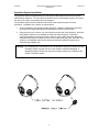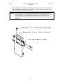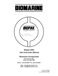
1
Facepiece Hydration System
User Manual
Biomarine
Biomarine-Ntron, Inc.
456 Creamery Way
Exton, Pennsylvania 19341 U.S.A.
Phone: (610) 524-8800
Fax: (610) 524-8807
Web: www.biopak240R.com
Document: A47D245, Revision: B
Part Number: B5-06-6000-21-0
January 2008
A47D245
BioPak 240R Facepiece Hydration System
User Manual
Revision: B
Table of Contents
Cautions and Limitations
4
Hydration System Installation
5
Hydration System Fitting
7
Hydration System Use
8
Maintenance Procedures
10
Specifications
12
Warranty
13
Illustrated Parts List
14
-2-
A47D245
BioPak 240R Facepiece Hydration System
User Manual
Revision: B
Cautions and Limitations
•
Failure to properly use and maintain this product could result in injury or death.
•
Never substitute, modify, add or omit parts. Use only exact replacement parts in the
configuration as specified by Biomarine Incorporated.
•
The on-going effectiveness and reliability of any protective breathing equipment is
dependent upon the user/owner’s standard of care in maintaining the equipment; and, the
user/owner’s expertise in using the equipment.
•
The user shall reference and abide by all cautions and limitations provided in the
respirator manuals.
•
The hydration system is suitable for use only with the Biomarine BioPak 240R respirator
and associated AV3000 facepiece.
•
The hydration system components have not been evaluated for use in applications
involving direct open flame or high radiant heat.
•
The hydration system components have not been evaluated for use in applications that
may expose the user to chemical, biological, radiological or nuclear agents (CBRN).
•
DO NOT attempt to fit the hydration system to any other manufacture or model of
respirator or facepiece other than the BioPak 240R.
•
The user bears full responsibility for properly maintaining this equipment including
inspections, cleaning, maintenance and use.
•
The hydration system shall be thoroughly cleaned and disinfected as well as leak checked
prior to each use.
•
If the respirator is to be utilized without the services of the hydration system it is strongly
suggested to remove the interface assembly from the facepiece and re-install the
facepiece voice emitter.
•
Hydration of a user is critical when working in hot conditions or when experiencing heavy
work-loads. Biomarine makes no claim that the use of the hydration system will prevent a
user from experiencing over heating of core body temperature or preventing user
dehydration.
•
It is the sole responsibility of the user to adequately select and utilize the drinking fluid to
be placed in the bladder of the hydration system. The hydration system was designed for
water-based liquid and was not designed with the intent to handle alcohol-based liquids.
-3-
A47D245
BioPak 240R Facepiece Hydration System
User Manual
Revision: B
Hydration System Installation
The hydration system will install directly into the BioPak 240R facepiece and onto the BioPak
240R harness waist belt. The user should be aware that use of the hydration system will require
the loss of one of two voice emitters from the facepiece.
The hydration system can be installed on either side of the facepiece as per the user’s
preference. Installation of the system is outlined below.
1. Prior to installation, the hydration system should be unpacked, washed and leak tested
according to procedures provided in the maintenance section of this manual.
2. Using a blunt pry bar, remove one voice emitter from one side of the facepiece. Note that
the hydration system can be installed on either side of the facepiece. Removal is
achieved by sliding the end of the pry bar under the voice emitter and gently sliding the
depressor around the circumference of the voice emitter while prying out. Save the voice
emitter for re-installation back into the facepiece should the hydration system not be
utilized during respirator use.
Warning: Do not damage the voice emitter cup of the facepiece during voice emitter removal.
Facepiece emitter cup shall not be cut, slit marred or otherwise damaged. A
damaged facepiece emitter cup may prevent proper sealing of the installed voice
emitter or hydration system.
-4-
A47D245
BioPak 240R Facepiece Hydration System
User Manual
Revision: B
3. Install the interface assembly of the hydration system into the voice emitter cup of the
facepiece. Slide the pry bar under the lip of the pocket and gently slide the depressor
around the circumference of the interface disk to pry the cup edge over the disk. Make
sure that the disk is fully seated within the cup.
Warning: Do not damage the voice emitter cup of the facepiece during hydration system
installation. Facepiece emitter cup shall not be cut, slit marred or otherwise
damaged. A damaged facepiece emitter cup may prevent proper sealing of the
installed voice emitter or hydration system.
-5-
A47D245
BioPak 240R Facepiece Hydration System
User Manual
Revision: B
4. Slide the waist belt of the BioPak harness through the straps on the rear of the reservoir
pouch. Installation should be made onto the side of the waist belt that is located directly
below the interface assembly on the facepiece.
Caution: If the respirator is to be utilized without the services of the hydration system it is
strongly suggested to remove the interface assembly and re-install the voice emitter
into the facepiece. This will keep the interface assembly end connector from
becoming filled with dirt and will remove the hanging tube of the interface from the
facepiece.
-6-
A47D245
BioPak 240R Facepiece Hydration System
User Manual
Revision: B
Hydration System Fitting
The hydration system is factory-supplied with a long tube exiting the top of the reservoir assembly
pouch. The user must first determine the desired routing of this tube up to the facepiece and fit
the tubing length to the specific user. The following procedure will guide the user through
hydration system fitting.
Required Equipment (not provided):
*
*
Marking Pen
Razor Knife
1. Don the BioPak as per directives in the BioPak User Manual.
2. Don the BioPak facepiece as per directives in the BioPak User Manual but do not connect
the respirator hoses to the facepiece.
3. Mount the reservoir to the right or left side respirator waist harness. The reservoir should
be located on the same side that the interface assembly of facepiece is mounted.
4. Route the tubing from the reservoir up to the interface assembly connection as desired. It
is suggested that the tubing be routed up the back of the user so that it will not interfere
with the user during use.
5. Once the tubing has been routed determine the required length of the tubing. It is best to
turn the head away from the reservoir location and mark the tubing to fit this distance.
6. Doff the Biopak and facepiece and remove the reservoir assembly from the waist belt.
7. Cut the reservoir tube to length as marked in step 5.
8. Carefully extract the fitting from the cut length of tubing and reinstall it into the end of the
reservoir tube.
9. Don the BioPak and facepiece and connect the reservoir tube to the facepiece interface
assembly.
10. Test head movement to verify that the hydration system does not restrict movement or
place the tubing into a position that could interfere with the user.
11. Connect the BioPak breathing hoses to the facepiece and turn on the oxygen supply as
per directives in the BioPak User Manual. Verify that the hydration system is positioned
as desired, that the hydration system does not restrict head movement and the that the
hydration system will not interfere with the user in an adverse manner.
12. Turn off the oxygen in the BioPak and doff the respirator and facepiece as per directives
in the BioPak User Manual.
13. Submit the hydration system to leak testing and cleaning as per the matinenance
procedures of this manual.
-7-
A47D245
BioPak 240R Facepiece Hydration System
User Manual
Revision: B
Hydration System Use
The hydration system consists of the interface assembly and the reservoir assembly. The
interface assembly will provide the pass through into the facepiece to admit liquid from the
reservoir. The reservoir assembly will hang from the waist belt of the BioPak harness and will
hold up to 1.5-liters of liquid. The two assemblies are connected together during use via the feed
tubing. Each assembly contains a valved connector on the end of the tubing. The valved
connectors will permit disconnection of the assemblies in the field without fear of liquid spilling or
internal BioPak atmosphere leakage.
Reference the illustrated parts list for system component identification.
Preparing for Use
1. In an atmosphere known to be free of toxins, fill the reservoir bag with up to 1.5-liters of
liquid. Filling is achieved by opening the reservoir pouch, unscrewing the bladder cap,
filling the bladder, replacing the bladder cap and closing the pouch. Make sure that the
bladder lid is securely tightened.
Caution: Do not overfill the bladder of the reservoir. Overfilling to volumes larger than 1.5liters may cause bladder rupture or weakening.
2. Don the BioPak as per instructions in the BioPak User Manual. If the reservoir is not
positioned on the waist belt of the Biopak place it into position now and buckle the waist
belt.
3. Perform the facepiece check valve test as detailed in the BioPak User Manual. This test
will also insure that the interface disk of the hydration system is fully seated in the
facepiece.
4. Route the tubing from the reservoir up to the interface assembly and connect. Note that
the tubing can be routed through and around the harness components of the BioPak to
keep the tubing from getting in the way of the user or from presenting a snag hazard. Do
not kink the tubing during routing.
¾
HINT: The tubing lengths can be adjusted by the user by removing one end, trimming
the tubing to the desired length and reattaching the tubing. Always perform a
hydration system leak test before use after trimming tubing lengths.
5. Lightly tug on the tubing connection between the reservoir and interface assemblies to
verify that it is fully connected and secure.
6. Once connected the tubing run will be open. Push in on the interface assembly tube to
push the bite-valve of the assembly into the mouth. Bite the bite-valve while sucking in to
draw liquid into the mouth. This will verify that the bite-valve is properly installed and that
the tubing run is open.
7. Withdraw the interface assembly tube to move the bite-valve out of the way.
8. The user is now ready to enter into the mission.
-8-
A47D245
BioPak 240R Facepiece Hydration System
User Manual
Revision: B
Mission Use
1. Drinking liquid from the reservoir can be achieved at any time by pushing in on the
interface assembly tube to push the bite-valve into the user’s mouth. Once the bite-valve
is positioned in the user’s mouth lightly bite down and suck to draw liquid into the mouth.
2. When it is not desired to drink the user should pull out on the interface assembly tube to
withdraw the bite-valve from interfering with the user. The interface has a positive stop to
prevent the user from pulling the tube completely out of the facepiece during operation.
3. If at any time during the mission the hydration develops a leak, the user should
immediately retire to a safe location to remove the hydration system and BioPak.
Leakage of the hydration system may result in rapid loss of internal breathing atmosphere
from the BioPak.
After Use
1. Retire to a safe location known to be free of toxins and adequately supplied with oxygen.
2. Disconnect the tubing run between the reservoir and interface assemblies by pushing in
the connector release button and pulling the tubing runs apart.
3. Close the oxygen bottle of the BioPak and doff the BioPak as per instructions in the
BioPak User Manual.
4. Submit the hydration system to maintenance for cleaning, drying and testing.
-9-
A47D245
BioPak 240R Facepiece Hydration System
User Manual
Revision: B
Maintenance Procedures
In order to keep the hydration system in peak condition it should be cleaned, dried and tested
after each use. This will alert the benchman of any damage, insure leak-free operation and
prevent the growth of mold or bacteria within the system.
Washing
1. Remove the reservoir assembly from the BioPak waist belt.
2. Open the pouch, remove the bladder and unscrew the bladder cap. Dump any remaining
liquid from the reservoir.
3. Fill the bladder with ½ to 1-liter of warm water and add one cleaning tablet,
B2-06-6001-74-0.
4. Replace the cap back onto the bladder and wait 15-30 minutes. During the waiting period
shake the bladder often and allow some of the water to travel up into the tube.
5. After the 15-30 minute period, open the bladder cap and discard the treated water. Rinse
the bladder well with fresh water and insure that no remnants of the tablet remain in the
bladder.
6. Allow the bladder assembly to air dry.
7. The interface assembly, installed in the facepiece, can be cleaned as per the standard
cleaning and disinfecting procedure for the facepiece as outlined in the Biopak Benchman
Manual.
8. Reinstall the bladder back into the reservoir pouch.
Testing
1. Inspect all of the components of the hydration system and replace any component that
appears to worn, damaged or appears suspect.
2. Remove the bite-valve from the interface assembly and connect the large diameter tubing
end of the Leak Test Fixture, B6-02-5002-60-0, to the open end of the interface assembly
feed tube where the bite-valve installs. The reservoir should be disconnected from the
interface assembly for this test.
3. Connect the small diameter tubing end of the Leak Test Fixture to the barbed fitting of the
BioPak Test Kit so that it is connected to the pressure gauge of the test kit.
4. Use the hand pump of the Leak Test Fixture to pump the internal volume of the hydration
system up to 6-8 inches water column pressure as read on the test kit gauge.
Hand Pump Operation: The following will provide details on operation of the hand
pump.
A. Squeeze the large bulb while depressing on both sides of the “S” button to push
air into the assembly.
B. Depress both sides of the “A” button to admit additional air into the pump bulb.
C. Repeat steps A and B multiple times until the proper pressure level is achieved.
D. Once the proper pressure level is achieved tightly close the pinch clamp located
on the short tubing run of the leak test fixture to hold the pressure in the
assembly. Do not rely upon the check valves of the hand pump to hold the
pressure in the assembly.
E. To depressurize the assembly, open the pinch valve then pull the connection tube
off the assembly.
- 10 -
A47D245
BioPak 240R Facepiece Hydration System
User Manual
Revision: B
5. Note the pressure reading of the test kit gauge and allow the assembly to sit undisturbed
for a 1-minute period. The pressure reading shall not drop by more than 0.40 inches
water column in the 1-minute period to be considered leak-tight.
6. Use Leak-Tek leak detection fluid from the test kit to identify leaking areas should the
assembly fail the leak test. Note that the entire assembly can also be submerged in water
to identify leak points. Repair or replace components that show evidence of leakage.
7. If the assembly passes the leak test then remove all equipment and place back onto the
BioPak or into storage until the next use.
8. Remove the reservoir from the pouch and fill with clean water. Close the fill cap of the
reservoir once filled.
9. Verify that water has traveled up the connection tube and that the connection tube port on
the reservoir bag is submerged. Observe the quick disconnect of the connection line and
reservoir bag tube fitting port and verify that no water is leaking from either of these
locations. Leaks from these locations will require replacement of the reservoir or the quick
disconnect fitting.
10. Once testing has completed, dump the water from the reservoir and allow to fully dry
before storing.
- 11 -
A47D245
BioPak 240R Facepiece Hydration System
User Manual
Revision: B
Specifications
Warning: The hydration system described in this manual is suitable only for use with the
Biomarine BioPak 240R and its associated facepiece. Use of this hydration system
with any other respirator or facepiece will void the warranty and may place the user in
a hazardous situation that could lead to injury or death.
Reservoir Capacity:
1.5-liters
Reservoir Bag Dimensions:
165 x 356 x 51 mm (6.5 x 14.0 x 2.0 inches)
Reservoir Bag Weight, Empty:
368 grams (13 ounces)
Reservoir Bag Weight, Full of Water:
1.9 kg (4.2 pounds)
Interface Assembly Weight:
36 grams (1.3 ounces)
Operational Temperature Range:
2 to 43oC (35 to 110oF)
Storage Temperature Range:
-40 to 49oC (-40 to 120oF)
Materials of Construction:
Interface Assembly:
Plastic: Flame-Rated Polycarbonate
O-Ring Seals: EPDM Rubber
Tubing: Silicone Rubber
Bite-valve: Silicone Rubber
Connector Fitting: Acetal
C-Ring Stop: Stainless Steel
Reservoir Assembly:
Pouch: Nylon, Acetal, Steel
Bladder: Proprietary CXC Film
Tubing: Silicone Rubber
Connector Fitting: Acetal
Features:
•
Bladder provides zero residual taste or smell.
•
Super-tough bladder construction results in maximum abrasion resistance.
•
Quick connect hose assembly means easy-on, easy-off when swapping out bladders
or cleaning components.
•
Bladder protected by an antimicrobial formula, Aquaguard ®
•
Large 80mm Rapid FillTM bladder cap.
•
Bladder in compliance with FDA notification No. 193.
•
Bladder EPA Approved.
TM
Rapid Fill
is a trademark of Nalgene.
- 12 -
A47D245
BioPak 240R Facepiece Hydration System
User Manual
Revision: B
Warranty
Biomarine warrants, subject to the terms below, that the goods will be free from defects in design, materials, and
workmanship for a period of three (3) years from the date that the goods are purchased by buyer, with the exception of
rubber components. Rubber and silicone rubber components are similarly warranted for a period of one (1) year from the
date of purchase. THIS WARRANTY DOES NOT APPLY TO OXYGEN CYLINDER HYDROSTATIC TESTING FOR
PERIODIC RECERTIFICATION OF THE PRESSURE VESSEL.
THE SOLE LIABILITY OF BIOMARINE FOR ALL PURPOSES SHALL BE TO REPLACE, AT THE SOLE OPTION OF
BIOMARINE, DEFECTIVE PARTS APPEARING WITHIN THE THREE OR ONE-YEAR PERIOD AS APPLICABLE.
BIOMARINE SHALL PROVIDE PARTS AT ITS OWN EXPENSE BUT ALL LABOR SHALL BE AT THE EXPENSE OF
THE BUYER. BIOMARINE SHALL HAVE NO OBLIGATION FOR REPLACEMENT UNLESS:
1.
BIOMARINE HAS RECEIVED WRITTEN NOTICE OF THE ALLEGED DEFECT WITHIN THIRTY (30) DAYS
FOLLOWING THE DISCOVERY OF THE DEFECT OR THIRTEEN (13) MONTHS FROM THE DATE OF
PURCHASE, WHICHEVER OCCURS SOONER; AND
2.
THE BUYER SUBMITS PROOF OF DATE OF PURCHASE WITH INVOICE OR EQUIVALENT DOCUMENTATION;
AND
3.
THE DEFECTIVE GOODS ARE PROMPTLY RETURNED BY BUYER, AT THEIR SOLE EXPENSE TO
BIOMARINE AT: 456 CREAMERY WAY, EXTON, PA 19341 USA; AND
4.
THE EQUIPMENT HAS NOT BEEN ALTERED; AND
5.
THE DEFECT OCCURS UNDER CIRCUMSTANCES OF PROPER USE IN ACCORDANCE WITH ALL
INSTRUCTIONS AND MANUALS PROVIDED TO THE BUYER.
It shall be the responsibility of the buyer to read carefully and abide by all instructions provided to the buyer in the
instruction manual or elsewhere. If buyer, and the employees of the buyer, did not abide by such instructions, then the
alleged defect shall not be deemed to have arisen under circumstances of proper use. The instructions for use of the
goods reflect the opinion of experts based on field use and tests. The instructions should be followed carefully. It is
impossible, however, to eliminate all risks inherently associated with the use of the goods. Unintended consequences
may result because of factors as weather conditions, the presence of other materials, or the use or manner of application
of the goods, all of which are beyond the control of Biomarine. The buyer shall assume all such risks.
Buyer shall be responsible for insuring that the goods are functioning properly at all times and shall not use any goods,
which are not functioning properly. If buyer uses goods when they are not functioning properly, then buyer agrees to
defend, indemnify and hold Biomarine harmless against all losses, damages, and injuries to persons or property as a
result of the use of the malfunctioning goods.
These warranties do not extend to the goods if they have been subjected to misuse, neglect, or accident, including
extended exposure to direct flames and/or caustic chemical products, after its delivery to buyer, nor does it extend to any
item that was modified or altered after its delivery to buyer.
IN NO EVENT WILL BIOMARINE BE LIABLE FOR ANY LOSS OR DAMAGE DIRECTLY OR INDIRECTLY ARISING
FROM THE DEFECTS OR FROM THE USE OF THE GOODS OR FOR CONSEQUENTIAL OR INCIDENTAL
DAMAGES, WHETHER IN CONTRACT, TORT, OR OTHERWISE, OR FOR PERSONAL INJURY OR PROPERTY
DAMAGE OR ANY FINANCIAL LOSS.
Any description of the goods contained in any documents to which these warranty provisions related, including any
quotations or purchase orders relating to the goods being delivered to buyer, are for the sole purpose of identifying the
goods, and any such description, as well as any sample or model which may have been displayed to or seen by buyer at
any time, have not been made part of the basis of the bargain and have not created or amounted to any warranty, express
or implied, that the goods would conform to any such description or any such sample or model.
EXCEPT AS SPECIFICALLY SET FORTH IN THESE WARRANTIES, BIOMARINE MAKES NO WARRANTIES,
EXPRESS OR IMPLIED, WHETHER ARISING BYLAW, CUSTOM, CONDUCT OR USAGE OF TRADE, INCLUDING
WARRANTIES AS TO MERCHANTABILITY, OR AS TO THE FITNESS OF THE GOODS FOR ANY PARTICULAR USE
OR PURPOSE, AND ANY WARRANTIES INCLUDING WARRANTIES AS TO MERCHANTABILITY AND FITNESS FOR
PARTICULAR USE OR PURPOSE AND THE RIGHTS AND REMEDIES PROVIDED HEREIN ARE EXCLUSIVE.
THESE WARRANTIES SHALL RUN TO THE BUYER ONLY AND SHALL NOT BE CONSTRUED AS A CONDITION.
Biomarine does not warrant that the goods are free from the rightful claim of any third person by way of infringement or
patents or other proprietary information or disclaims any warranty against such infringement.
The terms of these warranties shall apply to the product sold by Biomarine, except absorbent, filters and anti-fog lens
inserts which are considered “consumable item”, and as such are not covered by the terms of these warranties. No
waiver, alteration, or modification of the terms of these provisions shall be valid unless in writing and signed by an
executive officer of Biomarine.
These warranties shall not apply to accessories or devices purchased by Biomarine and attached to or made part of the
goods except that Biomarine warrants the (I) the installation of such items in the completed product shall so conform to
the installation instructions of the manufacturers thereof as not to invalidate such applicable warranties on such items as
are obtained by Biomarine from such manufacturers, and (ii) the workmanship incorporated in such installation shall be
free from defects.
- 13 -
A47D245
BioPak 240R Facepiece Hydration System
User Manual
Revision: B
Illustrated Parts List
A. Hydration System
ITEM #
QTY.
PART NUMBER
DESCRIPTION
REF
REF
-
B6-02-5002-52-0
B6-02-5002-70-0
Hydration System-Complete
2
Replacement Reservoir Assembly
1
2
3
1
1
1
B6-02-5002-59-0
B2-06-6001-72-0
B4-02-9563-00-0
Interface Assembly
Bite-Valve
Silicone Tubing-SPECIFY 3-INCHES
4
5
6
1
1
1
B4-03-4404-02-0
B4-03-4404-01-0
B4-02-9563-00-0
Quick Disconnect Fitting Insert
Quick Disconnect Fitting Body
Silicone Tubing-SPECIFY 60-INCHES
7
8
9
1
1
2
B2-02-4001-40-0
B2-06-6001-73-0
B2-06-6001-74-0
Hydration Bladder Pouch
1.5-Liter Bladder (located internal to pouch)
Cleaning Tablets, pack of 6 (not depicted)
10
1
B5-06-6000-21-0
User Manual (not depicted)
1
Note:
1.
Complete Hydration System includes items 1 through 10 plus Leak Test Fixture B6-02-5002-60-0.
2.
Replacement Reservoir Assembly includes items 5, 6, 7 and 8.
2
5
6
1
3
7
4
- 14 -
A47D245
BioPak 240R Facepiece Hydration System
User Manual
Revision: B
B. Leak Test Fixture
ITEM #
QTY.
PART NUMBER
DESCRIPTION
REF
1
2
1
1
B6-02-5002-60-0
B2-03-0002-00-0
B4-03-5404-02-0
Leak Test Fixture-Complete
Hand Pump
Barb Fitting
3
4
5
1
1
2
B2-06-6001-75-0
B4-02-9037-01-0
B4-03-4404-03-0
Pinch Clamp
Polyurethane Tubing-SPECIFY 6-INCHES
1
1/8 NPT x ¼” Male Barb Fitting
6
7
8
1
1
1
B4-03-4302-00-0
B4-03-4404-04-0
B4-02-9037-01-0
1/8 NPT Tee Fitting
1
1/8 NPT x 3/8” Male Barb Fitting
Polyurethane Tubing-SPECIFY 18-INCHES
9
10
1
AR
B4-02-9563-00-0
B5-07-1000-00-0
Silicone Tubing-SPECIFY 18-INCHES
Teflon Thread Tape
Notes:
1-Indicated fittings require Teflon thread sealing tape on pipe threads during assembly.
1
Connect to Interface Assembly
in Bite Valve Location
2
3
4
5
9
7
6
5
8
Connect to Test Kit
Pressure Gauge
- 15 -