1
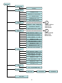
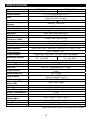
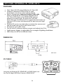
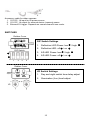
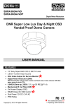
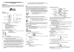
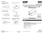
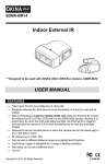
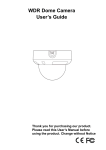
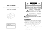
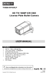
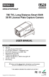
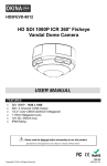
SDNR-8630
SDNR-8630P
Digital Noise Reduction
DNR Super Low Lux Day & Night OSD
Box Camera
5
Optional External IR
SDNR-8IR14
See page 14 for details
USER MANUAL
* Lens not included
FEATURES
• 1/3” Sony Super HAD CCD II
• 630 TV Lines
• Digital Noise Reduction (DNR) - Dramatically reduces both random and fixed
noise. It also reduces DVR disk space usage by up to 70%.
• 0.00039 (Sens-up, 256X) / 0.1 Lux (50 IRE @ F1.4)
• Mechanical IR Cut Filter (ICR)
1
• Built-in Microphone RCA Output
2
• On-Screen Display (OSD)
• RS485 Output for OSD Control
• Alarm Output: Black/Brown
3
4
• Dual Power 12V DC / 24V AC
New additional features x5
Copyright © 2012. All Rights Reserved.
** Replacing SDNR-F630DN-OSD
Please read the Manual before attempting to use this product.
Specifications and appearance are subject to change without notice.
Disposal of Old Electrical & Electronic Equipment (Applicable in the
European Union and other European countries with separate collection
systems).
This symbol on the product or on its packaging indicates that this product shall not be
treated as household waste. Instead it shall be handed over to the applicable collection
point for the recycling of electrical and electronic equipment. By ensuring this product is
disposed of correctly, you will help prevent potential negative consequences for the
environment and human health, which could otherwise be caused by inappropriate
waste handling of this product. The recycling of materials will help to conserve natural
resources. For more detailed information about recycling of this product, please contact
your local city office, your household waste disposal service or the shop where you
purchased the product.
CAUTION
1. Never point the camera toward the sun
Do not expose the lens directly to the sun or to strong light as this may damage the
pick-up device.
2. Handle this camera with care
Avoid any shock or bumping of the camera. Improper handling could damage the
camera.
3. Requires a proper operating environment
This camera is designed for indoor use. The allowable temperature range for operation
of this camera is between 14°F ~ 122°F / -10°C ~ 50°C.
2
4. Clean the front face or lens
It is recommended that the surface be cleaned every 3~6 months. Cleaning should be
done by using a chamois, a very fine soft cloth, lens tissue, or cotton tipped applicator
and ethanol to carefully remove any fingerprint or dust.
5. Check the power source voltage
The power source voltage should be within the specified range. (Camera must meet
the specifications). Camera must be connected to a surge protector at all times.
6. Objects and liquid entry
Never push objects of any kind into this camera as this may touch dangerous voltage
points of short out parts that could result in a fire or electric shock. Never spill any kind
of liquid on the video product.
7. Servicing
Do not attempt to service this video product by yourself as opening or removing covers
may expose you to dangerous voltage or other hazards. Refer all service to qualified
servicing personnel.
8. Damage requiring service
Unplug this video product from the wall outlet and refer service to qualified servicing
personnel under the following conditions:
a. When the power supply cord or plug is damaged.
b. If liquid has been spilled, or objects have fallen into the video product.
c. If the video product has been exposed to rain or water.
d. If the video product has been dropped or the cabinet has been damaged.
e. When the video product exhibits a distinct change in performance.
LIMITED WARRANTY
OKINA USA products are covered under warranty for one year from the date of purchase.
The warranty will automatically be voided if any of the following occurs:
1. Camera sticker is removed
If the camera sticker is removed, we will not be able to confirm any information
regarding when and where the product was purchased. We have no other way to verify
the purchase record without the serial number on the camera sticker; therefore, it
should not be removed.
2. Camera is modified in any way
If the camera is scratched, damaged, or modified in a manner not described in this
manual, the warranty will be voided immediately. It is the customer’s responsibility to
keep the camera in good condition.
3. Video or power cable is cut
The video cable and the power cable should not be tampered with. Cutting or
modifying of the cables will result in termination of the warranty.
3
PACKAGE CONTENTS
A.
B.
C.
D.
E.
F.
One (1) DNR Vandal Proof Box Camera with power/video cable
One (1) Remote Control
One (1) Allen Wrench
One (1) Motion Relay Output Wire
One (1) IRIS Connector
One (1) User Manual
A.
B.
D.
C.
E.
4
F.
Refer to #4 on
page 5 for details
* For any returns, please include all components listed above with original packaging in
Resalable Condition. Absolutely No Returns will be accepted if any component is
missing/damaged.
DIMENSION
Unit: mm
4
REAR PANEL
1
2
6
7
5
3
4
OR
PTZ-KB250
PTZ-KB050X
1. Video Output
2. Audio Output
3. RS485, +/- – See page 12 for PTZ controller key combination to call up OSD
menu, page 11 for OSD setting, and page 10 for wire & cable
4. MDO, Motion Detect Relay Output
a. Black & Brown = for External Alarm Device.
Set up on OSD Menu: Special Æ Motion Æ Motion View: On/Off
See page 11 for OSD setting and page 8 for application diagram
b. Red & Orange = not working for this model
5. 12V DC~24V AC, dual power
6. External IR (optional) – See page 15 for more details
7. On-Screen Display (OSD) Control
5
OPERATION
OSD Button (Menu):
1.
LENS menu: Select DC LENS, VIDEO DRIVE LENS or MANUAL IRIS LENS model
LENS
DC
BRIGHTNESS: 0 ~100
RETURN
VIDEO
MANUAL
2.
EXPOSURE menu: User can adjust electronic shutter speed, brightness (only for
manual iris lens), auto gain control, sensitivity-up level, back light compensation
(BLC) & Highlight Suppression (HSBLC) adjust and Digital WDR.
6
EXPOSURE
SHUTTER
1/50,1/60,FLK,1/100000, X2~x256
BRIGHTNESS 1 - 100
AGC
OFF, LOW, MIDDLE, HIGH
SENSE-UP
OFF, AUTO, X2~X256
BLC
HSBLC
LEVEL: 0 ~ 8
DEFAULT
LEFT/ RIGHT: 0 ~ 7
WIDTH: 0 ~ 8
TOP/BOTTOM: 0 ~7
HEIGHT: 0 ~ 8
RETURN
BLC
GAIN: LOW, MIDDLE,
DEFAULT
LEFT/ RIGHT: 0 ~ 7
WIDTH: 0 ~ 8
TOP/BOTTOM: 0 ~7
HEIGHT: 0 ~ 8
RETURN
OFF
D-WDR
INDOOR
OUTDOOR
OFF
RETURN
7
3.
WHITE BAL menu: User can adjust white balance effect for Auto Tracking White
balance (ATW), Auto White Balance (AWB), and indoor or outdoor environment.
WHITE BAL
ATW
AWB
AWCÆSET
MANUAL
BLUE 0~100
RED 0~100
RETURN
INDOOR
OUTDOOR
4.
DAY NIGHT menu: User can adjust camera auto change threshold with day and
night level to change Color or Black/White mode and force assign Color or
Black/White type.
Application Diagram:
Motion Detect Relay Output for External Alarm Device
Normally Close – No Polarity
4
Refer to #4a on page 5
for Camera Rear Panel
* Visit our website for more info.
on the Timer Relay Module
8
DAY NIGHT
AUTO
DELAY 0 ~ 63
S – LEVEL: 0 ~ 100
E – LEVEL: 0 ~ 100
RETURN
EXT
B/W
BURST: ON/OFF
RETURN
COLOR
5.
3DNR menu: User can adjust 3-Digital Noise Reduction level to improve night
environment effect.
3DNR
ON
LEVEL: 0 ~ 100
RETURN
OFF
6.
SPECIAL menu: User can setup Camera title, Digital effect (Freeze, Mirror, V-FLIP,
9
Rotate, D-ZOOM, GAMMA), RS485 which is very useful to connect test monitor,
DVR or keyboard to do the camera setting (Gamma ratio, Negative image effect,
Motion detection, Privacy mask and language choice). SYNC INT is only in 12V DC
power source. SYNC INT and L/L (line lock) are in 24V AC.
TIP
NOTE: All products in this section are not OKINA USA’s products. Please contact
us for more info. and referral.
For New Installations:
1.
US Wire Cable CCTV Balun Cable – 2 Pair UTP 24AWG with Power 18/2
24/4-18/2-Z-9B-500
RS485
Video – Use with Video
Power
2.
UTP Balun Passive Video Balun with Video, Power & Data
VPB111RJ
Data:
Power - F
Power - M
Video
Using Existing Coax & Power 18/2 to add RS485:
3.
AAS Video Power Over Coax – Power Guarantee 12V DC Series
VPOC2412DC
VPOC24DC-01
Camera Side
1 CH
Video & Power
Power Wire for RS485 +/-
10
A = Input 110~220V AC
B = Output 24V DC
C = Input 12V DC
SPECIAL
CAM TITLE
ON/OFF
D – EFFECT
FREEZE On/Off
MIRROR,V-FLIP,ROTATE
D – ZOOM On/Off
GAMMA 0.05~1.00
NEG. IMAGE On/Off
3
RS485
CAM ID 1 ~ 255: Assign ID
ID DISPLAY: ON/OFF
Refer to #3 on
page 5 for
Rear Panel
BAUD RATE 2400 ~ 57600
4
MOTION
AREA SELECT: AERA: 1 ~ 4
AREA DISPLAY: ON/OFF
Refer to #4 on
page 5 for
Rear Panel
LEFT / RIGHT: 0 ~ 100
WIDTH: 0 ~ 100
TOP / BOTTOM: 0 ~ 100
HEIGHT: 0 ~ 100
SENSITIVITY: 0 ~ 40
MOTION VIEW: ON/OFF
PRIVACY
AREA SELECT: AREA: 1 ~ 8
AREA DISPLAY : ON / OFF
LEFT / RIGHT: 0 ~ 100
WIDTH: 0 ~ 100
TOP / BOTTOM: 0 ~ 100
HEIGHT: 0 ~ 100
COLOR: 0 ~15
SYNC
INT ; L/L(PHASE0-359)
LANGUAGE
ENGLISH
RETURN
11
JAPANESE
CHINESE
SPECIAL menu (continued): User can setup Camera title, Digital effect (Freeze,
Mirror, V-FLIP, Rotate, D-ZOOM, GAMMA), RS485 which is very useful to connect test
monitor, DVR or keyboard to do the camera setting (Gamma ratio, Negative image
effect, Motion detection, Privacy mask and language choice). SYNC INT is only in 12V
DC power source. SYNC INT and L/L (line lock) are in 24V AC.
The key combination to enter the camera’s OSD menu with OKINA USA’s RS485 PTZ
controller PTZ-KB250X is SET + 95 + PRESET and for PTZ-KB050X is
PRESET+95+ENTER.
The protocol must be set to Pelco-D (not P)
For other RS485 PTZ controllers, the key combination may be different. If you have
trouble accessing the camera OSD, first check the wiring for polarity and continuity,
then please call our tech support line at (800) 872-9907 and have the model numbers
of your RS485 PTZ controller and camera available. Note that there are a lot of
different RS485 PTZ controllers in the market, so our tech support staff is limited to
only a few brands. The best option is to use OKINA USA’s RS485 PTZ controllers.
RS485 PTZ Controller Key Combination to Enter OSD Menu
7.
1.
PTZ-KB250X
SET + 95 + PRESET
2.
PTZ-KB050X
PRESET + 95 + ENTER
ADJUST menu: User can adjust camera sharpness and color parameter.
ADJUST
SHARPNESS: 0 ~ 31
BLUE: 0 ~ 100
RED: 0 ~ 100
RETURN
8.
RESET menu: User can reset camera setting back to factory default.
RESET
FACTORY RESET
RETURN
9.
EXIT menu: Exit OSD menu.
12
SPECIFICATION
Model
System
Image Sensor
DSP
Total Pixel
Synchronizing
System
Resolution
Scanning System
Minimum Illumination
S/N Ratio
WDR Function
Digital Noise
Reduction (DNR)
Day & Night
Digital Zoom
Auto Gain Control
White Balance
Back Light
Compensation
Picture Adjust
Electronic Shutter
Video Output
Audio Output
Camera Title
Sens-Up
Picture Effect
Alarm Relay Out
OSD Control
OSD Language
Mechanical IR Cut
Filter (ICR)
Lens
Lens Type
Power Source
Power Consumption
Power Current
Operating
Temperature
Storage Temperature
Dimension
Weight
SDNR-8630
SDNR-8630P
NTSC
PAL
1/3” Sony Super HAD CCD II
NVP2170 DN
High End ASIC Solution
811(H) x 508(V)
795(H) x 596(V)
Internal / Line Lock
630 TV Lines
2:1 Interlace
0.1 Lux (50 IRE @ F1.4) , 0.00039 (Sens-up, 256X)
More than 50db (AGC OFF)
Indoor / Outdoor / OFF
3 DNR; ON / OFF(0~100)
Auto / B/W / Color / EXT
ON / OFF (0~32x)
Low / Middle / High / OFF
AWB / AWC-SET / MANUAL / INDOOR / OUTDOR / ATW
BLC / HSBLC / OFF
Sharpness / CB_Gain / CR_Gain (level adjustable)
Auto 1/60 ~ 1/100,000 sec /
Auto 1/50 ~ 1/100,000 sec /
Flk X2~X256
Flk X2~X256
1.0 Vp-p / 75 ohm composite (BNC)
RCA
ON / OFF
ON / OFF (Selectable limit ~ 256X)
Freeze / Mirror / flip / 180° rotate / D-zoom / Gamma / Neg.
image
NO + COM
Button / Remote controller / RS485 Control keyboard /
Communication Pelco D
ENGLISH, CHINESE, JAPANESE
Auto / Day / Night
Not Included
C/CS, DC/Video
12V DC / 24V AC ± 10% / 1A
2.5W
230mA (Max)
14°F ~ 122°F / -10°C ~ 50°C
-4°F ~ 158°F / -20°C ~ 70°C
127.2(W) x 52.3(H) x 69.3(D) mm
0.79 lbs / 360 g
Specifications are subject to change without notice.
13
OPTIONAL EXTERNAL IR, SDNR-8IR14
FEATURES
•
•
•
•
•
•
•
•
Total 14pcs IR LED: 4pcs Reflection & 10pcs 5Ø
Parabolic reflected IR LEDs allow for even
illumination of a shot on near and far objects
Built-in Photodiode: Cadmium Sulfide (CdS) cells
within the External IR controls the Mechanical IR
Cut Filter (ICR) that’s in the SDNR-8630 camera,
allowing it to detect light. So when the CdS cells
detect low light, the External IR is triggered and activates the
camera’s ICR to work simultaneously for best day and night
images.
External IR can be mounted above or below the camera and
can be aimed high or low in the field of vision
IR distance up to 100ft / 30m
Can be used in different distance ranges and adjusts the IR high/low
Light sensor trigger is adjustable for a range of lighting conditions
Start delay can be set at different times
DIMENSION
Unit: mm
I/O CABLE
Just plug the External IR, SDNR-8IR, to DNR Super Low
Lux Day & Night OSD Box Camera, SDNR-8630.
14
1.
2.
3.
Accessory cable for other cameras.
1. 12V DC, 1A input for IR power source.
2. 12V DC, 1A output for external device (camera) power.
3. External 5V trigger. Depends on camera brand’s own mode.
SWITCHES
Rubber Cover
DIP Switch Settings
1. Reflection LED Power: low ½ / high ¾
2. Reflection LED: off ½ / on ¾
DIP Switch
3. 5Φ LED Power: low ½ / high ¾
½
4. 5Φ LED Power: off ½ / on ¾
¾
1
2
3
4
Rubber Cover
VR Switch Settings
1. Day and night switch time delay adjust
2. Illumination (Lux) level adjust
15
INSTALLATION
1.
Determine the location of the
External IR (top or bottom of camera
body).
2.
Put the tiny bracket on the screw
base.
3.
Center the bracket position
according to the two holes.
4.
Screw it tightly.
5.
Take the External IR and attach it to
the bracket with the small screw tie.
6.
Adjust the External IR to desired
position (forward or backward and
up or down).
MADE IN TAIWAN
Copyright © 2012. All Rights Reserved.
www.okinausa.com
16
T-416_T-416-IR
R201203-V06