1
FORKLIFT SAFETY
CONTENTS
MANITOU NORTH AMERICA, INC.
6401 IMPERIAL DRIVE
WACO, TX 76712-6803
For Parts Orders contact your Manitou North America Dealer or call:
Manitou North America, Inc. Parts Dept. (800) 425-3727 or (254) 799-0232
Parts Dept. Fax (254) 867-6504 Website: www.manitou-na.com
CALIFORNIA PROPOSITION 65 WARNING
Diesel Engine Exhaust and some of its constituents are known to the State of
California to cause cancer, birth defects or other reproductive harm.
MLT629T Series A
MLT633TLS Series A
MLT730TW(120)LS Series A
MT732T Series A
MT932 Series A
OPERATOR'S MANUAL
THIS OPERATOR'S MANUAL MUST BE KEPT IN THE LIFT TRUCK AND MUST BE READ AND
UNDERSTOOD BY USERS.
547785AS
R/11-10
FORKLIFT SAFETY
CONTENTS
FORKLIFT SAFETY
CONTENTS
- INTRODUCTION TO SAFETY -
- ROUGH TERRAIN FORKLIFT TRUCK
GENERAL SAFETY STANDARDS - - - I
- SAFTETY MESSAGES - - - - - - - - - - - - - - - - - - - - - - - - - - VII
- SAFETY DECALS - - - - - - - - - - - - - - - - - - - - - - - - - - - - - - VIII
- TABLE OF CONTENTS - - - - - - - - - - - - - - - - - - - - - - - - - - XV
R03-04
FORKLIFT SAFETY
CONTENTS
FORKLIFT SAFETY
CONTENTS
ROUGH TERRAIN FORKLIFT TRUCK
GENERAL SAFETY STANDARDS
I
FORKLIFT SAFETY
CONTENTS
ROUGH TERRAIN FORKLIFT TRUCK GENERAL SAFETY STANDARDS
STUDY THE OPERATOR/SERVICE MANUALS
The information in this manual provides general instructions for the safe operation and maintenance of your
forklift truck. This information is vital and must be clearly understood by the operator and serviceman. Study
this manual and the Rough Terrain Forklift Safety Manual (part no. 422494) thoroughly and carefully before
operating or servicing your forklift. Contact your dealer or Manitou North America, Inc. if you have any questions concerning your forklift, its operation, service or parts. Keep both manuals in the literature box on the
forklift available for reference. If either manual becomes illegible or is missing, contact your dealer for replacements immediately. This manual cannot cover every situation that might result in an accident. It is the responsibility of the operator to always remain alert for potential hazards and be prepared to avoid them!
ADDITIONAL RECOMMENDED LITERATURE:
ANSI / ITSDF B56.6 is the national consensus standard for rough terrain forklift trucks. It contains rules about
forklift safety, maintenance, safe operation, training, and supervision. Forklift owners should learn this standard and make it available for their operators, service personnel, and supervisors. These standards can be
obtained, free of charge, from the Industrial Truck Standards Development Foundation (ITSDF) on their website at www.itsdf.org. The following references are examples from the standard, addressing forklift operators:
A.) OPERATOR TRAINING QUALIFICATIONS
1.) The user shall ensure that operators understand that safe operation is the operator’s responsibility. The
user shall ensure that operators are knowledgeable of, and observe, all safety rules and practices.
2.) Create an effective operator training program centered around user company’s policies, operating conditions, and rough terrain forklift trucks. The program should be presented completely to all new operators and
not be condensed for those claiming previous experience.
3.) Information on operator training is available from several sources, including rough terrain forklift truck manufacturers, users, government agencies, etc.
4.) An operator training program should consist of the following:
a.) careful selection of the operator, considering physical qualifications, job attitude, and aptitude;
b.) emphasis on safety of stock, equipment, operator, and other personnel;
c.) citing of rules and why they were formulated;
d.) basic fundamentals of rough terrain forklift truck and component design as related to safety, e.g.,
in.-lb (N-m) loading, mechanical limitations, center of gravity, stability, etc.;
e.) introduction to equipment, control locations, and functions. Explain how they work when used
properly and problems when used improperly.
f.) supervise practice on operating course remote from normal activity and designed to simulate
actual operations, e.g., lumber stacking, elevating shingles to the roof, etc.;
g.) oral, written, and operational performance tests and evaluations during and at completion of the
course;
h.) refresher courses, which may be condensed versions of the primary
course, and periodic “on job” operator evaluation;
i.) understanding of nameplate data and operator instructions and warning information appearing on
the rough terrain forklift truck.
B.) GENERAL SAFETY PRACTICES
1.) Rough terrain forklift trucks can cause injury if improperly used or maintained.
2.) Only authorized operators trained to adhere strictly to all operating instructions shall be permitted to operate rough terrain forklift trucks. Unusual operating conditions may require additional safety precautions, training, and special operating instructions.
3.) Modifications and additions which affect capacity or safe operation shall not be preformed without the manufacturer’s prior written approval. Where such authorization is granted, capacity, operation, and maintenance
instruction plates, tags, or decals shall be changed accordingly.
4.) If the rough terrain forklift truck is equipped with front end attachment(s) or optional forks, the user shall see
that the truck is marked to identify the forks or attachment(s), show the approximate weight of the truck and
fork or attachment combination, and show the capacity of the truck with forks or attachment(s) at maximum
elevation with load laterally centered.
5.) The user shall see that all nameplates and caution and instruction markings are in place and legible.
6.) The user shall consider that changes in load dimension may affect rough terrain forklift truck capacity.
II
FORKLIFT SAFETY
CONTENTS
ROUGH TERRAIN FORKLIFT TRUCK GENERAL SAFETY STANDARDS (cont.)
B.) GENERAL SAFETY PRACTICES (cont.)
7.) Where steering can be accomplished with either hand and the steering mechanism is of a type that prevents road reactions from causing the handwheel to spin (power steering or equivalent), steering knobs may
be used. When used, steering knobs shall be of a type that can be engaged by the operator’s hand from the
top and shall be within the periphery of the steering handwheel.
8.) Experience has shown that rough terrain forklift trucks which comply with stability requirements are stable
when properly operated. However, improper operation, faulty maintenance, or poor housekeeping may contribute to a condition of instability and defeat the purpose of the requirements.
9.) Users shall give consideration to special operating conditions. The amount of forward and rearward tilt to
be used is governed by the application. Although the use of maximum rearward tilt is allowable under certain
conditions, such as traveling with the load lowered, the stability of a rough terrain forklift truck as determined
by standardized tests does not encompass consideration for excessive tilt at high elevations or the operation
of trucks with excessive off-center loads.
10.) Some of the conditions which may affect stability are ground and floor conditions, grade, speed, loading
(rough terrain forklift trucks equipped with attachments behave as partially loaded trucks even when operated
without a load on the attachment), dynamic and static forces, improper tire inflation, and the judgement exercised by the operator.
C.) OPERATING SAFETY RULES AND PRACTICES
1.) Safe operation is the responsibility of the operator.
2.) This equipment can be dangerous if not used properly. The operator shall develop safe working habits and
also be aware of hazardous conditions in order to protect himself, other personnel, the rough terrain forklift
truck, and other material.
3.) The operator shall be familiar with the operation and function of all controls and instruments before undertaking to operate the rough terrain forklift truck.
4.) Before operating any rough terrain forklift truck, truck operators shall have read and be familiar with the
operator’s manual for the particular truck being operated.
5.) Before starting to operate the rough terrain forklift truck:
a.) be in operating position and fasten seat belt;
b.) place directional controls in neutral;
c.) apply brakes;
d.) start engine.
6.) Do not start or operate the rough terrain forklift truck, any of its functions, or attachments from any place
other than the designated operator’s position.
7.) Keep hands and feet inside the operator’s designated area or compartment. Do not put any part of the
body outside the operator compartment of the rough terrain forklift truck.
8.) Never put any part of the body into the mast structure or between the mast and the rough terrain forklift
truck.
9.) Never put any part of the body within the reach mechanism of the rough terrain forklift truck or other attachments.
10.) Understand rough terrain forklift limitations and operate the truck in a safe manner so as not to cause injury
to personnel.
11.) Do not allow anyone to stand or pass under the elevated portion of any rough terrain forklift truck, whether
empty or loaded.
12.) Do not permit passengers to ride on rough terrain forklift trucks.
13.) Check clearance carefully before driving under electrical lines, bridges, etc.
14.) A rough terrain forklift truck is attended when the operator is less than 25 ft (7.6m) from the truck, which
remains in his view.
15.) A rough terrain forklift truck is unattended when the operator is 25ft (7.6m) or more from the truck, which
remains in his view, or whenever the operator leaves the truck and it is not in his view.
16.) Before leaving the operator’s position:
a.) bring rough terrain forklift truck to a complete stop;
b.) place directional controls in neutral;
c.) apply the parking brake;
d.) lower load-engaging means fully, unless supporting an occupied elevated platform;
e.) stop the engine;
f.) if the rough terrain forklift truck must be left on an incline, block the wheels;
g.) fully lower the load-engaging means.
17.) Maintain a safe distance from the edge of ramps, platforms, and other similar working surfaces.
18.) Do no move railroad cars or trailer with a rough terrain forklift truck.
III
FORKLIFT SAFETY
CONTENTS
ROUGH TERRAIN FORKLIFT TRUCK GENERAL SAFETY STANDARDS (cont.)
C.) OPERATING SAFETY RULES AND PRACTICES (cont.)
19.) Do not use a rough terrain forklift truck for opening or closing railroad car doors.
20.) In areas classified as hazardous, use only rough terrain forklift trucks approved for use in those areas.
21.) Report all accidents involving personnel, building structures, and equipment to the supervisor or as
directed.
22.) Do not add to, or modify, the rough terrain forklift truck.
23.) Do not block access to fire aisles, stairways, and fire equipment.
24.) For rough terrain forklift trucks equipped with a differential lock, the lock should not be engaged when driving on the road or at high speeds or when turning. If the lock is engaged when turning, there could be loss of
steering control.
25.) Observe all traffic regulations including authorized speed limits. Under normal traffic conditions, keep to
the right, maintain a safe distance, based on speed of travel, from the truck ahead; and keep the truck under
control at all times.
26.) Yield the right-of-way to pedestrians and emergency vehicles such as ambulances and fire trucks.
27.) Do not pass another truck traveling in the same direction at intersections, blind spots, or at other dangerous locations.
28.) Slow down and sound the audible warning device(s) at cross-aisles and other locations where vision is
obstructed.
29.) Cross railroad tracks at an angle wherever possible. Do not park closer than 6 ft (1.8m) to the nearest rail
of a railroad track.
30.) Keep a clear view of the path of travel and observe other traffic, personnel, and safe clearances.
31.) If the load being carried obstructs forward view, travel with the load trailing.
32.) Ascend or descend grades slowly and with caution.
a.) When ascending or descending grades in excess of 5%, loaded rough terrain forklift trucks
should be driven with the load upgrade.
b.) Unloaded rough terrain forklift trucks should be operated on all grades with the load-engaging
means downgrade.
c.) On all grades, the load and load-engaging means shall be tilted back, if applicable, and raised
only as far as necessary to clear the road surface.
d.) Avoid turning, if possible, and use extreme caution on grades, ramps, or inclines; normally
travel straight up or down.
33.) Under all travel conditions, operate the rough terrain forklift truck at a speed that will permit it to be brought
to a stop in a safe manner.
34.) Travel with load-engaging means or load low and, where possible, tilted back. Do not elevate the load
except during stacking.
35.) Make starts, stops, turns, or direction reversals in a smooth manner so as not to shift load and/or overturn
the rough terrain forklift truck.
36.) Do not indulge in stunt driving or horseplay.
37.) Slow down for wet and slippery surfaces.
38.) Before driving over a dockboard or bridge plate, be sure that it is properly secured. Drive carefully and
slowly across the dockboard or bridge plate, and never exceed its rated capacity.
39.) Do not drive rough terrain forklift trucks onto any elevator unless specifically authorized to do so.
Approach elevators slowly, and then enter squarely after the elevator car is properly leveled. Once on the elevator, neutralize the controls, shut off engine, and set brakes. It is advisable that all other personnel leave the
elevator before truck is allowed to enter or leave.
40.) Avoid running over loose objects on the roadway surface.
41.) When negotiating turns, reduce speed to a safe level, and turn steering handwheel in a smooth sweeping
motion. Except when maneuvering at a very low speed, turn the steering handwheel at a moderate, even rate.
42.) Use special care when traveling without load, as the risk of lateral overturning is greater.
43.) Improper use of stabilizer controls (if so equipped) could cause rough terrain forklift truck upset. Always
lower the carriage before operating stabilizer controls.
44.) For rough terrain forklift trucks equipped with lateral leveling:
a.) Always level the frame before raising the boom or mast, with or without a load.
b.) Lateral leveling should not be used to position an elevated load; instead, lower the load and
reposition the rough terrain forklift truck.
45.) Handle only stable or safely arranged loads.
a.) When handling off-center loads which cannot be centered, operate with extra caution.
b.) Handle only loads within the capacity of the rough terrain forklift truck.
c.) Handle loads exceeding the dimensions used to establish rough terrain forklift truck capacity
with extra caution. Stability and maneuverability may be adversely affected.
IV
FORKLIFT SAFETY
CONTENTS
ROUGH TERRAIN FORKLIFT TRUCK GENERAL SAFETY STANDARDS (cont.)
C.) OPERATING SAFETY RULES AND PRACTICES (cont.)
46.) When attachments are used, extra care shall be taken in securing, manipulating, positioning, and transporting the load. Operate rough terrain forklift trucks equipped with attachments as partially loaded trucks
when not handling a load.
47.) Completely engage the load with the load-engaging means. Fork length should be at least two-thirds of
load length. Where tilt is provided, carefully tilt the load backward to stabilize the load. Caution should be used
in tilting backward with high or segmented loads.
48.) Use extreme care when tilting load forward or backward, particularly when high tiering. Do not tilt forward
with load-engaging means elevated except to pick up or deposit a load over a rack or stack. When stacking
or tiering, use only enough backward tilt to stabilize the load.
49.) The handling of suspended loads by means of a crane arm (boom) or other device can introduce dynamic forces affecting the stability of a rough terrain forklift truck. Grades and sudden starts, stops, and turns can
cause the load to swing and create a hazard if not externally stabilized. When handling suspended loads:
a.) do not exceed the truck manufacturer’s capacity of the rough terrain forklift truck as equipped
for handling suspended loads.
b.) only lift the load vertically and never drag it horizontally;
c.) transport the load with the bottom of the load and the mast as low as possible;
d.) with load elevated, maneuver the rough terrain forklift truck slowly and cautiously, and only to
the extent necessary to permit lowering to the transport position;
e.) use tag lines to restrain load swing whenever possible.
50.) At the beginning of each shift and before operating the rough terrain forklift truck, check its condition,
giving special attention to:
a.) tires and their inflation pressure
b.) warning devices
c.) lights
d.) lift and tilt systems, load-engaging means, chains, cables, and limit switches
e.) brakes
f.) steering mechanism
g.) fuel system(s)
51.) If the rough terrain forklift truck is found to be in need of repair or in any way unsafe, or if it contributes to
an unsafe condition, the matter shall be reported immediately to the user’s designated authority, and the truck
shall not be operated until it has been restored to safe operating condition.
52.) If during operation the rough terrain forklift truck becomes unsafe in any way, the matter shall be reported
immediately to the user’s designated authority, and the truck shall not be operated until it has been restored to
safe operating condition.
53.) Do not make repairs or adjustments unless specifically authorized to do so.
54.) When refueling, smoking in the area shall not be permitted, the engine shall be stopped, and the operator shall not be on the rough terrain forklift
truck.
55.) Spillage of oil or fuel shall be carefully and completely absorbed or evaporated and fuel tank cap replaced
before restarting engine.
56.) Do not use open flames when checking electrolyte level in storage batteries, liquid level in fuel tanks, or
the condition of LPG fuel lines and connectors.
57.) Do not lift personnel with the forklift. If the forklift must be used to lift people, precautions for the protection of the personnel must be taken (see ITSDF B56.6, chapter 5.15 Elevating Personnel).
V
ROUGH TERRAIN FORKLIFT TRUCK GENERAL SAFETY STANDARDS (cont.)
D.) SUSPENDED LOADS
A jib or truss boom should ONLY be used to lift and place loads when the machine is stationary and the frame
is level. Transporting suspended loads must ALWAYS be done slowly and cautiously, with the boom and load
as low as possible. Use taglines to restrict loads from swinging, to avoid overturn.
The handling of suspended loads by means of a truss boom or other similar device can introduce dynamic
forces affecting the stability of the machine that are not considered in the stability criteria of industry test
standards. Grades and sudden starts, stops and turns can cause the load to swing and create a hazard.
Guidelines for “Free Rigging / Suspended Loads”
1.
DO NOT exceed the rated capacity of the telescopic handler as equipped for handling suspended
loads. The weight of the rigging must be included as part of the load.
2.
During transport, DO NOT raise the load more than 12 inches (305 mm) above the ground, or raise
the boom more than 45 degrees.
3.
Only lift the load vertically – NEVER drag it horizontally.
4.
Use multiple pickup points on the load when possible. Use taglines to restrain the load from swinging
and rotating.
5.
Start, travel, turn and stop SLOWLY to prevent the load from swinging. DO NOT exceed walking
speed.
6.
Inspect rigging before use. Rigging must be in good condition and in the U.S. comply with OSHA
regulation §1910.184, “Slings,” or §1926.251, “Rigging equipment for material handling.”
7.
Rigging equipment attached to the forks must be secured such that it cannot move either sideways or
fore and aft. The load center must not exceed 24 inches (610 mm).
8.
DO NOT lift the load with anyone on the load, rigging or lift equipment, and NEVER lift the load over
personnel.
9.
Beware of the wind, which can cause suspended loads to swing, even with taglines.
10.
DO NOT attempt to use frame-leveling to compensate for load swing.
WARNING
U.S. OSHA regulations effective November 8, 2010 (29 CFR Part 1926, Subpart CC - Cranes and Derricks in
Construction) include requirements for employers that use powered industrial trucks ("forklifts") configured
to hoist (by means of a winch or hook) and move suspended loads horizontally. In particular, this regulation
applies to any rough-terrain forklift (e.g., "telescopic handler") equipped with a jib or truss boom with a
hook (with or without a winch), or a hook assembly attached to the forks. [Note: This regulation is in
addition to the OSHA regulation that requires specific forklift operator training: §1910.178(l).]
When a forklift / telescopic handler is configured and used for hoisting, the employer must ensure that:
1.
Forklift, lift equipment and rigging have been inspected (each shift, month and year) and are in
good, safe condition and properly installed.
2.
An operator's manual and applicable load charts are on the forklift.
3.
Work zone ground conditions can support the equipment and load. Any hazardous conditions in the
work area have been identified, and the operator notified.
4.
Equipment is being used within its rated capacity and in accordance with the manufacturer's
instructions.
VI
5.
Operator and crew members have been trained in the safe use and operation of the equipment,
including how to avoid electrocution.
6.
During use, no part of the equipment, load line or load will be within the minimum clearance
distance specified by OSHA [10 feet (3.0 m), and more for lines rated over 50 kV] of any energized
power line, and any taglines used are non-conductive.
7.
In addition, for lift equipment with a rated capacity greater than 2000 lbs. (907 kg), the employer
must ensure that:
a.) An accessible fire extinguisher is on the forklift;
b.) Monthly and annual inspections are performed and documented, and records retained (three
months for monthly, one year for annual);
c.) Before November 10, 2014, operators must have had the additional training and qualification /
certification required by OSHA regulations §1926.1427 and §1926.1430.
Note: Refer to the full text of the OSHA crane regulation (29 CFR Part 1926, Subpart CC) for a detailed
description
VII
ROUGH TERRAIN FORKLIFT TRUCK GENERAL SAFETY STANDARDS (cont.)
CONCLUSION:
1.) ATTEND OPERATOR TRAINING CLASSES
The forklift operator must clearly understand all instructions concerning the safe operation of the forklift and all
safety rules and regulations of the work site. They must have successfully completed a training coarse in
accordance with the Powered Industrial Truck Standard (29 CFR 1910.178) as described by the Occupational
Safety and Health Administration (OSHA). They must be qualified as to their visual, hearing, physical, and
mental ability to operate the equipment safely. NEVER use drugs or alcohol while operating a forklift! NEVER
operate or allow anyone to operate a forklift when mental alertness or coordination is impaired! An operator
on prescription or over-the-counter drugs must consult a medical professional regarding any side effects of the
medication that may impair their ability to safely operate the forklift.
2.) CREATE A MAINTENANCE PROGRAM
OSHA recommends a maintenance log, listing repairs requested and completed, for each forklift. Also, “lock
out tag procedures” should be utilized. If the forklift malfunctions; park it safely, remove the key, tag “Do Not
Use”, and report the problem to the proper authority or authorized service personnel immediately.
ROUGH TERRAIN FORKLIFT TRUCK GENERAL SAFETY STANDARDS (cont.)
2.) CREATE A MAINTENANCE PROGRAM (cont.)
For the best forklift performance and operation, a maintenance program is required. Use the hour meter on
the instrument panel to keep maintenance properly scheduled (see SECTION TWO - “Servicing Schedule”).
For repairs on major components (engine, transmission, etc.), contact your nearest dealer for a Repair Manual.
Do not operate a forklift that is damaged or does not function properly. Only authorized personnel may make
repairs or adjustments to the lift truck. After repairs, the lift truck must be tested for safe operation before
returning to service.
3.) FORKLIFT KNOWLEDGE
Forklift trucks can cause serious injury if improperly used or maintained. Study all of the manuals provided for
your forklift model. Learn the locations and meanings of all safety decals. If any decals are illegible or missing, have them replaced immediately. Make sure all safety features provided by the original manufacturer are
in place and function properly. Do not operate a forklift with damaged, missing or unsafe components. Have
it repaired by authorized service personnel. Learn the functions of all controls, gauges, indicator lights, etc. on
the forklift. Know the speed/gear ranges, braking and steering capabilities, load ratings and clearances. When
referring to the location of forklift components, the terms “left”, “right”, “front”, and “rear” are related to the operator seated normally, facing forward in the operator’s seat. If you have any questions about the forklift, consult your supervisor. Failure to fully understand or obey safety warnings can result in serious injury or death!
4.) WORK SITE KNOWLEDGE
Before operating on a work site, learn the rules for movement of people, forklifts and all other traffic. Check
the size, weight, and condition of the loads you will be expected to handle. Verify that they are properly
secured and safe to transport. Learn where the loads are to be placed, planning your route for a safe
approach, watching for hazardous conditions. Will a signal man be required to help place the load? Remove
any debris which may cause tire damage or rupture. Plan your route around problem areas or have them corrected. Inform the supervisor of any unsafe conditions observed at the site. Examples of hazards: power
lines, cables, low clearance structures, garage doors, telephone pole guide lines, fencing, loose lumber, building materials, drop-offs, trenches, rough/soft spots, oil spills, deep mud, steep inclines, railroad tracks, curbs,
etc.. NEVER approach power lines, gas lines or other utilities with the forklift! Always verify that local,
state/provincial and federal regulations have been met. Report any accidents involving personnel, building
structures, and equipment to the supervisor immediately. Always remain alert - conditions are constantly
changing at the work site!
TECHNICAL SUPPORT
All data provided in this manual is subject to production changes, addition of new models, and improved product designs. If a question arises regarding your forklift, please consult your dealer or K-D Manitou, Inc. for the
latest information. When ordering service parts or requesting technical information, be prepared to quote the
applicable Model/Serial Numbers.
VIII
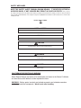
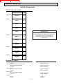
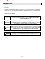
SAFETY MESSAGES
NOTE THE SAFETY ALERT SYMBOL (SHOWN BELOW). IT IDENTIFIES POTENTIAL
HAZARDS WHICH, IF NOT AVOIDED MAY RESULT IN INJURY OR DEATH! Also, observe
the safety messages places throughout this manual; providing special instructions, telling you when to take precautions
and to identify potential hazards. The safety messages are highlighted and outlined in a box similar to those shown in the
examples below.
SAFETY ALERT SYMBOL
NOTE or NOTICE
Provides information, special instructions or references about the lift truck.
IMPORTANT
Precautions which must be taken to avoid damage to the lift truck.
CAUTION
Indicates a potentially hazardous situation which, if not avoided, may result in minor or
moderate injury. May also alert unsafe practices.
WARNING
Indicates a potentially hazardous situation which, if not avoided, may result in death or
serious injury!
DANGER
Indicates an imminently hazardous situation which, if not avoided, will result in death or
serious injury.
CALIFORNIA PROPOSITION 65 WARNING
Diesel Engine Exhaust and some of its constituents are known to the State of California
to cause cancer, birth defects or other reproductive harm.
WARNING: Battery posts, terminals and related accesories and related accessories
contain lead and lead compounds. Wash hands after handling.
IX
FORKLIFT SAFETY
CONTENTS
SAFETY DECALS
The purpose of this chapter is to introduce you to the safety messages, decals, and nameplates found on
your forklift truck. The decals are identified by name, part number, location, and a brief description. (The
forklift model logos, and other misc. decals not shown, can be found in your forklift parts manual.) The
decals illustrated may not be exactly the same as those installed on your forklift; installation of the decals
varies depending on the forklift model, series, decal updates, etc.. The size and location of some decals
limit the amount of information that can be placed upon it. For this reason, additional detailed information
not found on the decals is provided through-out this manual.
Every decal placed on the lift truck is important; they are constant reminders of safety and instructions that
should never be taken for granted. Even experienced operators can be seriously injured or killed by ignoring, refusing to enforce, or forgetting to follow safe operating procedures! Do not assume you know all safety issues concerning the decals. Before operating the lift truck; learn the meaning(s) of the decals as
described in this manual. If any decal becomes illegible or missing, have it replaced immediately! Always
replace decals using the same decal part no., unless otherwise specified by the manufacturer. For replacement decals not found in your parts manual, contact your nearest dealer. If you have any questions, contact
your supervisor or nearest dealer for advice before operating your forklift!
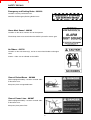
801011
Before Starting - 801011
(Boom equipped models). Location: on the brake fluid cover panel (to
the left and below the dash panel).
Safety Instructions - 420792
(Mast equipped models). Location: on or near the operator manual
storage case, and/or on the dash panel.
Instructions for the forklift operator; before operating the forklift.
Use of Seat Belt - 801012
(Boom equipped models). Location: to the right of the
operator, near the hydraulic control lever.
Instructs the operator to always wear the seat belt during
operations, and never jump from an over-turning forklift.
X
FORKLIFT SAFETY
CONTENTS
SAFETY DECALS
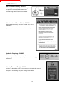
Emergency and Parking Brake - 801010
Location: near the park brake lever.
Identifies the Emergency/Parking Brake Lever.
Alarm Must Sound - 496162
Location: on the dash, in direct view of the operator.
The backup alarm must sound when the forklift is placed in reverse gear.
No Riders - 420732
Location: on the cab entrance(s), and on or near wheel fenders and engine
cover.
Informs: riders are not allowed on the forklift.
Clear of Raised Boom - 801006
(Boom equipped models). Location: on both sides
of the boom nose.
Keep away from unsupported boom.
Clear of Power Lines - 801007
(Boom equipped models). Location: on both sides
of the boom nose.
Keep away from power lines.
XI
FORKLIFT SAFETY
CONTENTS
SAFETY DECALS
Use of Frame Leveling - 801013
(Boom equipped models). Location: to the right of
the operator near the hydraulic control lever.
Frame leveling notice; load must be lowered.
Attachment and Boom Safety - 801009
(Boom equipped models). Location: on both sides of the
boom nose.
Important reminders of attachment and boom safety.
Hydraulic Coupling - 234805
Location: near the quick-disconnect adapters.
Stop the engine and release hydraulic pressure before changing
attachments.
Rotating Fan and Belt(s) - 801008
Location: on the radiator near the fan, and on any fan belt/pulley cover(s).
Keep hands and clothing away from rotating fan and belts.
XII
FORKLIFT SAFETY
CONTENTS
SAFETY DECALS
Gear Shift Pattern - 33460
(4-speed transmission models). Location: near the gear shift lever.
Identifies the gear shift pattern of the forklift transmission.
Steering Mode - 184276
(4 wheel steer equipped models). Location: near the steering mode selection lever.
Identifies the steering mode selection.
221322
Mineral Oil (Brake Reservoir) - 221322 or 234800
Location: attached to the brake fluid reservoir.
Refer to the Operator/Service Manual for the correct brake fluid
(mineral oil) to be used in the brake system.
234800
XIII
FORKLIFT SAFETY
CONTENTS
SAFETY DECALS
Hydraulic Oil - 234798 or 76573
Location: on the hydraulic tank or filler cap.
Identifies the hydraulic reservoir (tank) or filler cap.
Hydraulic Oil - 61024
Location: on the hydraulic tank.
Identifies the hydraulic reservoir (tank).
Anti-Freeze - 234799
Location: on the radiator, near the radiator filler cap.
Indicates required minimum to maximum anti-freeze protection (-220F to -400F).
Diesel Fuel - 161101
Location: on the fuel tank, near the filler cap.
Identifies the fuel tank, and use of diesel fuel.
No Step - 496735
Location: varies, depending on the forklift model.
Instructs personnel not to use the designated area as a step.
Do Not Tow - 494918
(Hydrostatic equipped models). Location: on the
dash, in view of the operator.
Towing the forklift will damage the transmission;
refer to the operator’s manual.
XIV
FORKLIFT SAFETY
CONTENTS
SAFETY DECALS
Attachment Warning - 421016
(Boom equipped models). Location: on the boom coupler,
near where the retaining shaft is installed.
Reminder to operator; install attachment retaining shaft and
safety pin before operations.
Hook Here - 24653
Location: at points provided on the forklift, where straps or chains may be attached to
secure the forklift to a trailer during transport.
Fork Safety - 426641
(Mast equipped models). Location: on the front and back side of the mast’s outer rails,
at eye level (4 required).
Instructs personnel not to travel beneath or upon the lift truck forks.
Pinch Point, Large, 2.5 x 4.5 in. - 426643
Pinch Point, Small, 1.5 x 2.75 in. - 426642
(Mast equipped models). Location: on the front and rear sides
of the mast cross bracing.
Keep fingers away from the mast
crossbracing.
HAND THROTTLE DANGER - 804784
(Boom equipped models, option). Location: Near the hand throttle mechanism.
Reminder to operator; set parking brake before operating hand throttle.
Disengage hand throttle before leaving the forklift.
XV
FORKLIFT SAFETY
CONTENTS
SAFETY DECALS
Acid in Battery - 801014
Location: in or near the battery
storage compartment.
Addresses battery hazards.
Jump Start Battery - 801015
Location: in or near the battery storage
compartment.
Jump start instructions.
Attachment Plate - 425995
Location: on the optional removeable forklift attachment.
Important manufacturer information about the attachment. Record this information for use
when contacting the maufacturer for parts and service.
Overhead Guard Data Plate - B6109
Location: attached to the overhead guard.
Overhead guard conformity.
496550
Forklift Data Plate - 496550
(Boom equipped models)
Forklift Data Plate - 496538
(Mast equipped models)
Location: within the operator’s compartment.
Important forklift truck identification. Record
this information for use when contacting the
manufacturer for parts and service.
XVI
496538
FORKLIFT SAFETY
CONTENTS
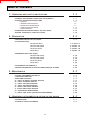
TABLE OF CONTENTS
1 - OPERATING
AND SAFETY INSTRUCTIONS
– ORIGINAL REPLACEMENT PARTS AND ATTACHMENTS
– DRIVER'S OPERATING INSTRUCTIONS
• CAUTION
• GENERAL INSTRUCTIONS
• OPERATING INSTRUCTIONS
• HANDLING INSTRUCTIONS
• LOAD HANDLING
– MAINTENANCE INSTRUCTIONS OF THE LIFT TRUCK
– BEFORE STARTING UP A NEW LIFT TRUCK
2 - DESCRIPTION
1-1
1-3
1-4
1-4
1-5
1-7
1 - 11
1 - 13
1 - 16
1 - 18
2-1
– IDENTIFICATION OF THE LIFT TRUCK
– CHARACTERISTICS
MLT 629 Turbo Série A
MLT 633 LS Turbo Série A
MLT 730 LS Turbo Série A
MT 732 Turbo Série A
MT 932 Série A
2-4
2 - 6 and 2 - 8
2 - 6 and 2 - 12
2 - 6 and 2 - 16
2 - 6 and 2 - 20
2 - 6 and 2 - 24
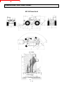
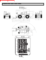
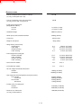
– DIMENSIONS AND LOAD CHART
MLT 629 LS Turbo Série A
MLT 633 LS Turbo Série A
MLT 730 LS Turbo Série A
MT 732 Turbo Série A
MT 932 Série A
2
2
2
2
2
– INSTRUMENTS AND CONTROLS
– DESCRIPTION AND USE OF ELECTRIC AND HYDRAULIC OPTIONS
2 - 28
2 - 45
3 - MAINTENANCE
–
–
–
–
–
–
–
–
–
–
–
10
14
18
22
26
3-1
FILTERS CARTRIDGES AND BELTS
LUBRICANTS AND FUEL
SERVICING SCHEDULE
A - DAILY OR EVERY 10 HOURS SERVICE
B - EVERY 50 HOURS SERVICE
C - EVERY 250 HOURS SERVICE
D - EVERY 500 HOURS SERVICE
E - EVERY 1000 HOURS SERVICE
F - EVERY 2000 HOURS SERVICE
G - OCCASIONAL MAINTENANCE
H - EVERY TWO YEARS (OPTION AIR CONDITIONING)
4 - ADAPTABLE
-
ATTACHMENTS IN OPTION ON THE RANGE
– INTRODUCTION
– PICKING UP THE ATTACHMENTS
3-3
3-4
3-6
3-8
3 - 11
3 - 18
3 - 22
3 - 28
3 - 33
3 - 34
3 - 40
4-1
4-3
4-5
XV
FORKLIFT SAFETY
CONTENTS
FORKLIFT SAFETY
CONTENTS
1 - OPERATING
AND SAFETY
INSTRUCTIONS
1-1
FORKLIFT SAFETY
CONTENTS
1-2
FORKLIFT SAFETY
CONTENTS
ORIGINAL REPLACEMENT PARTS AND ATTACHMENTS
ALL MAINTENANCE ON OUR LIFT TRUCKS MUST BE CARRIED OUT USING ORIGINAL PARTS.
BY ALLOWING NON-ORIGINAL PARTS TO BE USED,
YOU RUN THE RISK
- Legally, of being liable in the event of an accident.
- Technically, of causing breakdowns to occur or of reducing your lift truck's service life.
IMPORTANT
Using counterfeit parts or components not approved by the manufacturer
may put an end to contract warranty terms and lead
the maker to withdraw the lift truck's certificate of compliance.
BY USING ORIGINAL PARTS DURING MAINTENANCE OPERATIONS,
YOU ARE LEGALLY
COVERING
YOURSELF
- Any user who procures parts from another quarter does so at his own risk.
- Any user who modifies his lift truck or has it modified by a service company, must consider
that a new item of equipment has been brought onto the market and therefore takes liability
for it.
- Any user who copies original parts or has them copied is taking a risk from the legal viewpoint.
- The certificate of compliance only binds the maker for parts chosen or produced under the
maker's control.
- The practicalities of maintenance terms are set out by the maker. The maker is in no way
liable in the event of the user not complying with such terms.
YOU GET THE
BENEFIT OF THE
MANUFACTURER'S
KNOW-HOW
THE MANUFACTURER BRINGS TO THE USER,
- His know-how and skill.
- Guaranteed quality work.
- Original replacement parts.
- Help with preventive maintenance.
- Effective help with diagnosing faults.
- Enhancements gained from feedback.
- Training for operating staff.
- Only the manufacturer knows the details of the lift truck design and therefore has the best
technological capability to carry out maintenance.
1-3
FORKLIFT SAFETY
CONTENTS
DRIVER'S OPERATING INSTRUCTIONS
WARNING
WHENEVER YOU SEE THIS SYMBOL IN MEANS:
WARNING ! BE CAREFUL ! YOUR SAFETY OR THE SAFETY OF THE LIFT TRUCK IS AT RISK.
- Most accidents connected with the use, maintenance and repair of the lift truck are due to non application of the basic
safety instructions. By being aware of the risks to which you are exposed and by taking the necessary preventive
measures, you should be able to avoid accidents occurring.
- Any operation or maneuver not described in the instructions is prohibited, however, any person who does use another
method must first ensure that he is not putting himself, another person or the lift truck in danger.
- The manufacturer is not able to anticipate all possible risk situations. Therefore the safety instructions and notices
given in the user manual and on the lift truck are not exhaustive.
Any bending of the rules in safety notices or the user, maintenance or repair instructions for your lift truck may result in
serious, or even fatal, accidents.
We would remind users of the risks in driving at excessive speed with regard to traffic conditions, particularly :
- Risk of loss of control on a poor-quality track.
- Increased stopping distance.
The user must remain in full control of his lift truck and should :
- Adapt his speed to each situation in order to maintain his own safety, that of others and of his
equipment.
- Always be aware of his stopping distance.
On the basis of experience, there are a number of possible situations in which operating the lift truck is contraindicated. Such foreseeable abnormal uses, the main ones being listed below, are strictly forbidden.
- The foreseeable abnormal behaviour resulting from ordinary neglect, but does not result from any wish to put the
machinery to any improper use.
- The reflex reactions of a person in the event of a malfunction, incident, fault, etc. during operation of the lift truck.
- Behavior resulting from application of the "principle of least action" when performing a task.
- For certain machines, the foreseeable behavior of such persons as : apprentices, teenagers, handicapped persons
and trainees tempted to drive a lift truck. Truck drivers tempted to operate a truck to win a bet, in competition or for
their own personal experience.
The person in charge of the equipment must take these criteria into account when assessing whether or not a person
will make a suitable driver.
1-4
FORKLIFT SAFETY
GENERAL
CONTENTS
INSTRUCTIONS
A - DRIVER’S OPERATING INSTRUCTIONS
- Read the operator's manual carefully, making sure you understand it.
- The operator’s manual must always be kept in the lift truck, in the place provided and in the language understood by
the operator.
- Respect the safety notices and instructions given on the lift truck.
- It is mandatory to replace all plates or stickers which are no longer legible or which have become worn or damaged.
B - AUTHORIZATION TO OPERATE
(Or refer to the legislation for each particular country)
- Only qualified personnel may use the lift truck. Its use is subject to authorization to operate being given by the
appropriate manager in the user establishment.
- The user should always carry this authorization to operate with him while he is using the lift truck.
- The driver is not competent to authorize the driving of the lift truck by another person.
- In addition, the vehicle should be used in accordance with good practice for the profession.
C - MAINTENANCE
- The user must immediately advise his superior if his lift truck is not in good working order or does not comply with the
safety notice.
- The operator is prohibited from carrying out any repairs or adjustments himself, unless he has been trained for this
purpose. He must keep the lift truck properly cleaned if this is among his responsibilities.
- Carry out daily maintenance (See A - DAILY OR EVERY 10 HOURS SERVICE in SECTION 3 - MAINTENANCE).
- Ensure tires are adapted to the nature of the ground.
. SAND tires.
. LAND tires.
. Snow chains.
There are optional solutions, consult your agent or dealer.
WARNING
IMPORTANT
A worn or damaged tire can result in the lift truck being temporarily out of service.
The fitting of foam inflated tires is prohibited and is not guaranteed by the manufacturer, excepting
prior authorization.
- For your own and other people's safety, it is forbidden to modify the structure and settings of the various components of
your lift truck yourself (Hydraulic pressure, relief valve calibration, I.C. engine running speed, addition of extra
equipment etc.). The same holds with regard to any suppression or modification of the safety systems, in which case
the maker would no longer be liable.
WARNING
Regular inspection of your lift truck is mandatory if it is to be kept in conforming condition. The
frequency of such checks are defined by the current legislation of the country in which the lift
truck is being operated.
Maintenance or repairs other than those detailed in part : 3 - MAINTENANCE must be carried out
by qualified personnel (Consult your agent or dealer) and under the necessary safety conditions
to maintain the health of the operator and any third party.
1-5
FORKLIFT SAFETY
CONTENTS
D - ENVIRONMENT
- A lift truck operating in an area without fire extinguishing equipment must be equipped with an individual extinguisher.
There are optional solutions, consult your agent or dealer.
- Take into account climatic and atmospheric conditions of the site of utilization.
IMPORTANT
For operation under average climatic conditions, i.e. : between -15 °C and + 35 °C (5°F to 95°F),
correct levels of lubricants in all the circuits are checked in production. For operation under more
severe climatic conditions, before starting up, it is necessary to drain all the circuits, then ensure
correct levels of lubricants using lubricants properly suited to the relevant ambient temperatures. It
is the same for the cooling liquid.
. Protection against frost (See LUBRICANTS AND FUEL in SECTION 3 - MAINTENANCE).
. Adaptation of lubricants (Ask your dealer for information).
. Engine filtration.
. Lighting (Working headlight).
Optional solutions exist, consult your dealer.
WARNING
Use of a lift truck is prohibited in protected areas (e.g. refinery, explosive atmosphere). For use in
these areas, specific equipment is available as an option. Consult your dealer.
1-6
FORKLIFT SAFETY
CONTENTS
OPERATING
INSTRUCTIONS
A - DRIVER’S OPERATING INSTRUCTIONS
- Wear clothes suited for driving the lift truck, avoid loose clothes.
- Never operate the vehicle when hands or feet are wet or soiled with greasy substances.
- For increased comfort, adjust the driver’s seat to your requirements and adopt the correct position in the driver’s cab.
- The operator must always be in his normal position in the driver’s cab. It is prohibited to have arms or legs, or generally
any part of the body, protruding from the driver’s cab of the lift truck.
- Always remember to fasten your seat belt and adjust it to your requirements.
- The control levers must never in any event be used for any other than their intended purposes (e.g. climbing onto or
down from the lift truck, etc.).
- If the control components are fitted with a forced operation (lever lock) device, it is forbidden to leave the cab without
first putting these controls in neutral.
- Never allow a passenger to travel on the lift truck in the driver’s cab.
B - BEFORE STARTING THE LIFT TRUCK
- If the lift truck is new, refer to BEFORE STARTING UP A NEW LIFT TRUCK in SECTION 1 - OPERATING AND
SAFETY INSTRUCTIONS.
- Check the condition of the tires and the tire pressures (See CHARACTERISTICS in SECTION 2 - DESCRIPTION).
- Before starting the lift truck, check the different levels :
. Engine oil.
. Hydraulic reservoir oil.
. Cooling liquid.
. Braking oil.
- Also check for possible leakage of oil, fuel or liquid from the lift truck.
- Check the closing and locking of the hood.
- Whatever his experience as a truck driver is, the operator is advised to familiarize himself with the position and
operation of all the controls and instruments before operating the lift truck.
C - STARTING THE LIFT TRUCK
SAFETY NOTICE
WARNING
The lift truck must only be started up or maneuvered when the operator is sitting in the driver’s
cab, with his seat belt adjusted and fastened.
- Never try to start the lift truck by pushing or towing it.
IMPORTANT
Such operation may cause severe damage to the transmission. If necessary, to tow the lift truck in
an emergency, the transmission must be placed in the neutral position (See
H - OCCASIONAL MAINTENANCE in SECTION : 3 - MAINTENANCE).
INSTRUCTIONS
- Make sure that the forward/reverse lever is in neutral.
- Turn the ignition key to the position I to activate the electrical system.
- Check the level on the fuel level gauge.
- Turn the ignition key to position II to preheat for 15 seconds.
IMPORTANT
Do not engage the starter motor for more than 15 seconds and carry out the preheating for 10
seconds between unsuccessful attempts.
1-7
FORKLIFT SAFETY
CONTENTS
- Press the accelerator pedal and turn the ignition key fully: the I.C. engine should then start. Release the ignition key
and let the I.C. engine run at idle.
- Check all control instruments immediately after starting up, when the I.C. engine is warm and at regular intervals during
use, so as to quickly detect any faults and to be able to correct them without any delay.
- If an instrument does not show the correct display, stop the I.C. engine and immediately carry out the necessary repairs.
D - DRIVING THE LIFT TRUCK
SAFETY NOTICE
- Always drive the lift truck with the forks or attachment at approximately 300 mm (12 in) from the ground, i.e. In the
transport position.
- Familiarize yourself with the lift truck on the terrain where it will be used.
- Ensure that the service brakes and the sound alarm are working properly.
- Drive according to, and at an appropriate speed for, the conditions and state of the terrain.
- Slow down before executing a turn.
- In all circumstances make sure you are in control of your speed.
- On damp, slippery or uneven terrain, drive slowly.
- Brake gently, never abruptly.
- Only use the lift truck’s forward/reverse lever from a stationary position and never do so abruptly.
- Do not drive with your foot on the brake pedal or with the parking brake on.
- Always remember that hydrostatic type steering is extremely sensitive to movement of the steering wheel, so turn it
gently and not abruptly.
- Never leave the I.C. engine on when the lift truck is unattended.
- Look in the direction you are travelling and always keep clear visibility of the road. Use the left and right rear view
mirrors frequently and ensure that they are kept in good condition, are clean and correctly adjusted.
- When working at night, ensure that your lift truck is fitted with full beam lights. There are optional solutions, consult your
agent or dealer.
- Drive around obstacles.
- Never move onto a loading platform without having first checked :
. That it is suitably positioned and made fast.
. That the unit to which it is connected (tractor-trailer, etc.) will not shift.
. That this platform is prescribed for the total weight of the lift truck to be loaded.
. That this platform is prescribed for the width of the lift truck.
- Never move onto a foot bridge, floor or freight lift, without being certain that they are prescribed for the weight and size
of the lift truck to be loaded and without having checked that they are in sound working order.
WARNING
Take extreme care with loading platforms, trenches, scaffolding, recently dug and/or backfilled
ground.
- The loaded lift truck must not travel at speeds in excess of 12 km/h (7.5 mph).
INSTRUCTIONS
- Raise the forks or attachment to the transport position approximately 300 mm (12 in) from the ground.
- Engage the gear required (See INSTRUMENTS AND CONTROLS in SECTION 2 - DESCRIPTION).
- Select the desired steering mode.
- Shift the forward/reverse lever to the desired direction of travel.
- Release the parking brake and accelerate gradually until the lift truck moves off.
1-8
FORKLIFT SAFETY
CONTENTS
E - STOPPING THE LIFT TRUCK
SAFETY NOTICE
- Before stopping the lift truck after a long working period, leave the I.C. engine idling for a few moments, to allow the
coolant liquid and oil to lower the temperature of the I.C. engine and transmission.
IMPORTANT
Do not forget this precaution: frequently stopping the engine will raise the temperature of some
components, with risk of badly damaging them.
- Never leave the ignition key in the lift truck when the lift truck is unattended.
- When the lift truck is stationary, place the forks or attachment on the ground, place the gear lever in neutral (As model
of lift truck), apply the parking brake and put the forward/reverse lever in neutral.
- If the driver has to leave his cab, even for a moment, it is essential to place the gear lever in neutral (As model of lift
truck), apply the parking brake and put the forward/reverse lever in neutral.
- Make sure that the lift truck is not stopped in any position that will interfere with the traffic flow and at least 6 feet from
the track of a railway.
- In the event of prolonged parking on a site, protect the lift truck from bad weather, particularly from frost (Check the
level of antifreeze), close the rear window, lock the cab door and ensure that the hood is properly secured.
INSTRUCTIONS
- Park the lift truck on flat ground or on an incline that is less than 15 %.
- Release the accelerator pedal and stop the lift truck.
- Place the forward/reverse lever in neutral.
- Apply the parking brake.
- Place the gear lever in neutral (As model of lift truck).
- Retract entirely the boom.
- Lower the forks or attachment to rest on the ground.
- Stop the I.C. engine with the ignition switch.
- Remove the pressure in the hydraulic circuits by using the hydraulic controls.
- Remove the ignition key.
- Check the closing and locking of the door, rear window and hood.
WARNING
Before leaving your driver's cabin, ensure that you have carried out all operations for stopping
the lift truck, for your safety and the safety of others.
F - DRIVING THE LIFT TRUCK ON THE PUBLIC HIGHWAY
SAFETY INSTRUCTIONS
- When driving a lift truck on roads open to public traffic, observe the provisions of the Highway Code.
- Lift truck drivers, driving on the public highway, must abide by the general provisions relative to highway traffic.
- The lift truck must conform to the provisions of the Highway Code. If necessary, optional solutions exist, consult your
dealer.
CAUTION
Transport of loads on the public highway is forbidden and attachments mounted on the lift truck
must be fitted with equipment in accordance with regulations or removed.
1-9
FORKLIFT SAFETY
CONTENTS
INSTRUCTIONS
- Ensure that the flashing light is in position and that it is working.
- Check the good working order and cleanness of lights, indicators and windscreen wiper.
- Control the alignment of the wheels and select the steering mode HIGHWAY TRAFFIC.
- Check the adjustment of the rear view mirrors.
- Ensure that the fuel level is sufficient.
- Put the boom in the retracted position and the attachment at 300 mm (12 in) from the ground.
- On the road, set off in 3rd gear and go into 4th (As model of lift truck) when the conditions and state of the road allow. In
hilly areas, set off in 2nd gear and go into 3rd when the conditions and state of the road allow.
WARNING
While on the road do not use the transmission cut-off to maintain engine braking on the lift truck.
G - OPERATING THE LIFT TRUCK WITH A TRAILER ON A PUBLIC HIGHWAY
- For using a trailer, consult the regulations in force in your country (Maximum travel speed, braking, maximum weight of
trailer, etc.).
- Do not forget to connect the lift truck’s electrical equipment to that of the trailer.
- Do not use a non-braked trailer if the unit weight of a load exceeds that imposed by the highway code.
- Do not use a non-braked trailer without braking equipment for the trailer on the lift truck.
- Do not forget to connect the lift truck’s braking equipment to that of the trailer.
- The maximum vertical pull on the trailer hook must not exceed 1500 daN (3372 lb).
- The authorized total towed weight (A.T.T.W.) must not exceed the maximum weight authorized by the manufacturer
(Consult the manufacturer’s plate on your lift truck).
- When driving with a trailer, set off in 2nd gear and go into 3rd when the conditions and state of the road allow.
H - OPERATING THE LIFT TRUCK WITH A FRONT-END ATTACHMENT ON A PUBLIC HIGHWAY
- For driving with an attachment, check the regulations currently applicable in your country.
- The attachment must not exceed the overall width of the lift truck.
- The length of the entire unit must not exceed the overall length by 6 m (19.68 ft).
- Do not mask the lighting range of the front headlamps.
- Set the attachments shields in place or disassemble the attachment.
IF NECESSARY, CONSULT YOUR DEALER.
1 - 10
FORKLIFT SAFETY
CONTENTS
HANDLING
INSTRUCTIONS
A - GENERAL
- Ensure the correct functioning of your lift truck’s attachments.
- Do not attempt to carry out operations which exceed the capacities of your lift truck or attachments.
- It is prohibited to increase the counterweight value in any way.
- It is strictly prohibited to carry or to lift up persons using the lift truck, unless the vehicle is specially equipped for this
purpose and has the corresponding certificate of conformance for lifting people.
- Avoid traveling for a long distance in reverse.
B - ATTACHMENTS
- Ensure that the attachment is correctly fitted and locked to its frame.
- Conform to the limits on the load chart for the lift truck and/or attachment.
- Ensure that pallets, cases, etc, are in good order and suitable for the load to be lifted.
- Position the forks perpendicular to the load to be lifted, taking account of the load’s center of gravity.
- Never lift a load with a single fork.
- Never lift a sling load with a single fork or with the carriage. Optional solutions exist, consult your dealer.
- Ensure that the quick-disconnect fittings on the attachment system are clean and protected.
IMPORTANT
Before each change of an attachment with hydraulic function, in order to avoid damaging the the
quick-disconnect fittings:
- Place the attachment in the closed position, flat on the ground (For unstable attachments,
ensure they are secured using wedges).
- Switch off the I.C. engine.
- Remove pressure from the attachment hydraulic system using the hydraulic controls.
C - ENVIRONMENT
- Take care when raising the load that no object or person is in the way of movement and do not make any incorrect
maneuvers.
- In the case of work near aerial lines, ensure that the safety distance is sufficient between the working area of the lift
truck and the aerial line.
WARNING
You must consult your local electrical agency. You could be electrocuted or seriously injured if you
operate or park the lift truck too close to power cables. You are strongly advised to ensure that the
safety rules on the site conform to the local regulations in force regarding all types of work carried
out close to power cables.
- Do not allow anybody to come near the working area of the lift truck or pass beneath an elevated load.
- When using the lift truck on a slope, before raising the boom, ensure that the ground is horizontal. However, lift trucks
fitted with a slope corrector and/or stabilizers can work on a steeper transverse slope providing this slope can be
corrected (See G - HORIZONTAL POSITION OF THE LIFT TRUCK in next chapter - LOAD HANDLING).
- Travelling on a longitudinal slope :
• Drive and brake gently.
• Moving without load : Forks or attachment facing downhill.
• Moving with load : Forks or attachment facing uphill.
- Ensure that scaffolding, loading platform or pile are capable of
bearing the weight.
- Ensure the stability and solidity of the ground before depositing a
load.
1 - 11
FORKLIFT SAFETY
CONTENTS
D - HANDLING
- Always consider safety and only transport balanced and correctly secured loads to avoid any risk of tipping.
- Fully engage forks under the load and move it in the transport position (The forks 300 mm (12 in) from the ground, the
boom retracted to the maximum and the carriage sloping backwards).
- For obvious reasons regarding the lift truck’s stability and clear visibility of the surrounding environment, only move the
lift truck when the boom is in the transport position.
- Do not maneuver the lift truck with the boom in the raised position unless under exceptional circumstances and then
with extreme caution, at very low speed and using gentle braking. Ensure that visibility is adequate and get another
person to guide you along if necessary.
- Never shift the position of the load while the lift truck is in motion.
- The simultaneous use of two lift trucks to handle heavy or bulky loads is a dangerous maneuver, requiring specific
precautions to be taken. This should only be done in exceptional circumstances and in the presence of a handling
manager.
- Never drive too fast or brake abruptly when carrying a load.
- When handling, drive in 3rd gear and reduce to 2nd in cramped spaces.
- Check the load, particularly when turning corners and especially if it is very bulky.
- Secure unstable loads.
- Handle loads with caution, at slow speed, without sudden jerks when moving them at significant heights and boom
extention.
WARNING
In the event of high winds or storms, do not carry out handling work that jeopardizes the stability of
the lift truck and its load, particularly if the load catches the wind badly.
- Do not change direction sharply and at high speed.
DANGER
In the event of the lift truck overturning, do not try to leave the cabin during the incident.
YOUR BEST PROTECTION IS TO STAY FASTENED IN THE CABIN.
- Apply the parking brake when lifting or depositing a difficult load or when on an incline.
- Do not stop the lift truck with the load in an elevated position.
- Do not leave a laden lift truck with the parking brake applied on an incline which exceeds 15%.
E - VISIBILITY
- Constantly keep clear visibility of the road, either direct view (looking backwards when reversing) or indirect view using
the panoramic rear view mirrors to check for people, animals, holes, obstacles, change of slope, etc.
- Since visibility can be reduced on the right side when the boom is raised, ensure clear visibility of the road before
raising the boom and before undertaking any maneuvers.
- If the visibility in forward motion is not sufficient because of the bulkiness of the load, drive in reverse motion. This
maneuver must remain exceptional and for short distances.
- Ensure you have good visibility (Clean windows, adequate lighting, correctly adjusted rear view mirror, etc.).
- Signalling and lighting on the lift truck must take into account the conditions of use. In addition to series equipment
mounted on your lift truck, a certain number of options are available, such as: road lighting, stop lights, flashing light,
reverse lights, reverse buzzer alarm, front light, rear light, light at the boom head, etc. Consult your agent or dealer.
IF NECESSARY, CONSULT YOUR DEALER.
1 - 12
FORKLIFT SAFETY
LOAD
CONTENTS
HANDLING
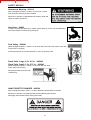
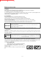
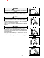
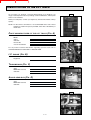
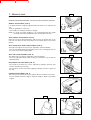
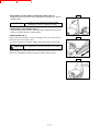
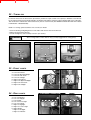
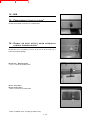
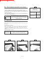
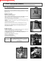
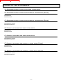
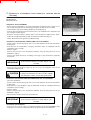
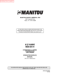
A - WEIGHT OF LOAD AND CENTER OF GRAVITY
CAUTION
A
Carrying a load greater than the rated capacity for the
lift truck or for the attachment is prohibited.
24 in
- Before taking up a load, you must know its weight and its center of gravity.
- The load chart relating to your lift truck is valid for a weight with its center of
gravity 24 in from the heel of the forks (Fig. A). For a higher center of
gravity, consult your agent or dealer.
- For irregular loads, determine the center of gravity in the transverse
direction before handling (Fig. B).
B
CAUTION
For loads with a moving center of gravity (e.g. liquids), take account of the
variations in the center of gravity in order to determine the load to be
handled (Consult your agent or dealer) and be vigilant and take extra care
to limit these variations as far as possible.
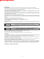
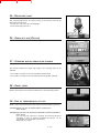
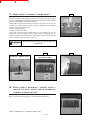
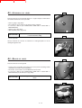
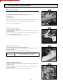
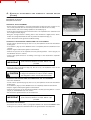
B - TAKING UP A LOAD ON THE GROUND
- Position the lift truck perpendicular to the load, with the boom retracted and
the forks in a horizontal position (Fig. C).
- Adjust the fork spread and centering in connection with the load (Fig. D)
(Optional solutions exist, consult your dealer).
C
WARNING
Beware of the risks of trapping or injuring limbs when manually adjusting the
forks. Always maintain an equal distance between the forks and the center
of the carriage in order to keep the load completely stable.
- Move the lift truck forward slowly (1) and bring the forks to stop in front of
the load (Fig. E), if necessary, slightly lift the boom (2) while taking up the
load.
- Apply the parking brake and place the forward/reverse lever in neutral.
- Slightly lift the load (1), incline the carriage (2) backwards in the transport
position (Fig. F).
D
CAUTION
E
Tilt the load sufficiently backwards to ensure its stability (loss of load on
braking) without upsetting the balance of the load in so doing.
1
2
F
2
1
1 - 13
FORKLIFT SAFETY
CONTENTS
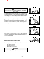
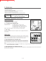
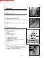
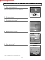
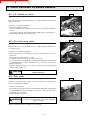
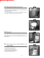
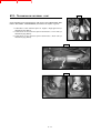
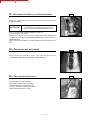
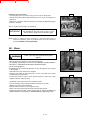
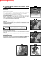
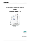
C - TAKING UP A HIGH LOAD ON TIRES
G
WARNING
Under no circumstances should you pick up a load if the lift truck is not in a
horizontal position. (See paragraph G - HORIZONTAL POSITION OF THE
LIFT TRUCK).
- Ensure that the forks will easily pass under the load.
- Position the lift truck perpendicular to the load and with the forks in a
horizontal position (Fig. G) maneuvering gently and carefully (See E VISIBILITY in chapter HANDLING INSTRUCTIONS for visibility of the road).
H
CAUTION
Be constantly aware of the distance between the forklift and pile; using the
shortest possible length of boom to place the forks under the load (Fig. G).
- Bring the forks to stop in front of the load (Fig. H). Apply the parking brake
and place the forward/reverse lever in neutral.
- Slightly lift the load (1) and incline the carriage (2) backwards to stabilize the
load (Fig. I).
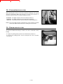
CAUTION
I
Tilt the load sufficiently backwards to ensure its stability (loss of load on
braking) without upsetting the balance of the load in so doing.
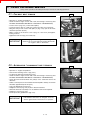
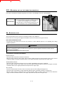
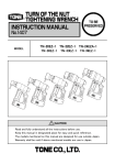
- If possible lower the load without shifting the lift truck. Lift the boom (1) to
release the load, retract (2) and lower the boom (3) to bring the load into the
transport position (Fig. J).
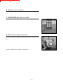
- If this is not possible, back the lift truck up. Maneuvering very gently and
carefully (See E - VISIBILITY in chapter HANDLING INSTRUCTIONS for
visibility of the road), back up the lift truck (1) to release the load, retract (2)
and lower the boom (3) to bring the load into the transport position (Fig. K).
2
1
J
1
2
3
K
2
3
1
1 - 14
FORKLIFT SAFETY
CONTENTS
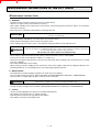
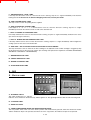
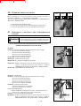
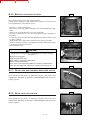
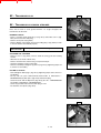
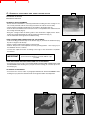
D - LAYING A HIGH LOAD ON TIRES
L
WARNING
Under no circumstances should you lay down a load if the lift truck is not in
a horizontal position. (See paragraph G - HORIZONTAL POSITION OF
THE LIFT TRUCK).
- Approach the load in the transport position in front of the pile (Fig. L).
- Lift and extend the boom (1) (2) until the load is above the pile, if necessary
move the lift truck forward (3) (Fig. M) maneuvering very gently and carefully
(See E - VISIBILITY in chapter : HANDLING INSTRUCTIONS for visibility of
the road). Apply the parking brake and place the forward/reverse lever in
neutral.
- Place the load in a horizontal position and lay it down on the pile by lowering
and retracting the boom (1) (2) in order to position the load correctly (Fig.
N).
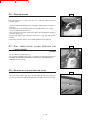
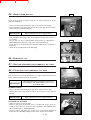
- Free the forks by alternately retracting and lifting the boom (3) (Fig. N) or, if
possible, by reversing the lift truck (3) (See E - VISIBILITY in chapter :
HANDLING INSTRUCTIONS for visibility of the road). Then bring the boom
into the transport position.
M
2
1
3
N
3
1
2
3
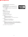
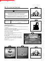
E - TAKING UP A NON PALLETIZED LOAD
- Tilt the carriage (1) forwards and extend the boom (2) while simultaneously
crowding the carriage backwards to slip the forks under the load (Fig. O). If
necessary, wedge the load.
O
F - N/A
2
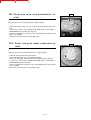
G - HORIZONTAL POSITION OF THE LIFT TRUCK
3
Apart from the transverse slope of the ground, several parameters can upset
the horizontal position of the lift truck.
• The tire pressure.
• The stability of the ground.
• The balance of the load.
• Strong wind or stormy conditions.
WARNING
Before any handling work, check the points above and ensure that the lift
truck is completely horizontal.
1 - 15
1
FORKLIFT SAFETY
CONTENTS
MAINTENANCE INSTRUCTIONS OF THE LIFT TRUCK
MAINTENANCE
INSTRUCTIONS
A - GENERAL
- Read the operator's manual carefully and ensure you understand it.
- Stop the I.C. engine, when an intervention is necessary.
- Wear clothes suitable for the maintenance of the lift truck, avoid wearing jewelry and loose clothes. Tie and protect
your hair, if necessary.
- Ensure the area is sufficiently ventilated before starting the lift truck.
IMPORTANT
Make sure that the disposal of process materials and of spare parts is carried out in total safety
and in a ecological way.
- Carry out all repairs immediately, even if the repairs concerned are minor.
- Repair all leaks immediately, even if the leak concerned is minor.
- Do not attempt to loosen unions, hoses or any hydraulic component with the circuit under pressure.
WARNING
The handling and removal of the balancing valves which may be fitted to the cylinders of your lift
truck can be dangerous. A balancing valve must only be removed when the cylinder concerned is
at rest and the hydraulic circuit is depressurised.
This operation can only be carried out by authorised staff.
- Do not smoke or approach the lift truck with a flame, when the fuel tank is open or is being filled.
- Take care not to burn yourself (Exhaust, radiator, I.C. engine, etc.).
- Disconnect the negative cable terminal (-) from the top of the battery before working on the electrical circuit or on the lift
truck (e.g., Welding).
- Do not drop metallic items on the battery.
- When carrying out electric welding work on the lift truck, connect the negative cable from the equipment directly to the
part being welded, so as to avoid high tension current passing through the alternator.
B - MAINTENANCE
- The maintenance and the keeping in compliance of the lift truck are mandatory.
- Carry out daily maintenance (See A - DAILY OR EVERY 10 HOURS SERVICE in SECTION 3 - MAINTENANCE).
- Do not run the I.C. engine without air filter, or with oil, water or fuel leaks.
WARNING
Wait for the I. C engine to cool before removing the radiator cap.
- Change the filter cartridges (See FILTERS CARTRIDGES AND BELTS in SECTION 3 - MAINTENANCE).
C - LEVELS
- Use the recommended lubricants (Never use contaminated lubricants).
- Do not fill the fuel tank when the I.C. engine is running.
- Only fill up the fuel tank in areas specified for this purpose.
- Do not fill the fuel tank to the maximum level.
1 - 16
FORKLIFT SAFETY
CONTENTS
D - WASHING
- Clean the lift truck or at least the area concerned before servicing.
- Remember to close the door and the rear window of the cab.
- During washing, avoid the articulations, electrical components, and connections.
IMPORTANT
Protect components susceptible of being damaged; from penetration of water, steam or cleaning
agents; particularly electrical components, connections, and the injection pump.
- Clean the lift truck of any fuel, oil or grease trace.
FOR ANY INTERVENTION OTHER THAN REGULAR MAINTENANCE, CONSULT YOUR DEALER.
1 - 17
FORKLIFT SAFETY
CONTENTS
BEFORE STARTING UP A NEW LIFT TRUCK
INTRODUCTION
- Our lift trucks have been designed for easy handling by the operator and maximum ease of maintenance for the
mechanic.
- However, before operating the lift truck, the user should carefully read and understand the various chapters of this
manual which has been provided to solve driving and maintenance problems. By following these instructions the user
will be able to take full advantage of the versatility of this lift truck.
- The operator must familiarize himself with the positions and functions of all the controls and instruments before
operating the lift truck.
IMPORTANT
Do not attempt to start a new lift truck before the following checks have been carried out :
LUBRICATION
- Check that all the correct grades of oils and greases that are required are available; see SERVICING SCHEDULE in
SECTION 3 - MAINTENANCE and top up if necessary.
IMPORTANT
For operation under average climatic conditions, i.e. between -15 °C and + 35 °C (5°F to 95°F),
correct levels of lubricants in all the circuits are installed at production. For operation under more
severe climatic conditions, before starting up, it is necessary to drain all of the circuits and install
correct levels of lubricants suited to the relevant ambient temperatures. It is the same for the
engine cooling system (Contact your dealer for information, if necessary).
DRY AIR FILTER
- Ensure that the air filter is undamaged and not blocked.
- Tighten the fastening devices if necessary.
IMPORTANT
Never run the engine with the air filter removed or damaged.
COOLING SYSTEM
- Do not start the lift truck without checking the radiator coolant level or if the fan belt is damaged or broken.
HYDRAULIC SYSTEM
- Check by a visual examination that there are no leaks from the hoses, connections and unions. If necessary, tighten or
repair the defective connections.
- Also check that the tank oil level is correct.
BRAKING SYSTEM
- Check by a visual examination that there are no leaks from the hoses, connections and unions. If necessary, tighten or
repair the defective connections.
- Also check the oil level in the tank.
WARNING
Ensure that the recommended oil is used, in order to avoid serious damage to the braking system.
TIRES
- Make sure that the wheel nuts are correctly tightened (See A - DAILY OR EVERY 10 HOURS SERVICE in
SECTION 3 - MAINTENANCE) and that the tire pressures are correct (See CHARACTERISTICS in SECTION 2 DESCRIPTION).
FUEL SYSTEM
- Check that all fuel lines are secured.
- If necessary drain the fuel filter and bleed the fuel system of air.
ELECTRICAL CIRCUIT
- Check the level and the density of the electrolyte in the battery (See B - EVERY 50 HOURS SERVICE in SECTION 3 MAINTENANCE).
- Check the components of the electrical system, connections, and fastening devices.
IF NECESSARY, CONSULT YOUR DEALER.
1 - 18
FORKLIFT SAFETY
CONTENTS
2 - DESCRIPTION
2-1
FORKLIFT SAFETY
CONTENTS
2-2
FORKLIFT SAFETY
CONTENTS
2-3
FORKLIFT SAFETY
CONTENTS
IDENTIFICATION OF THE LIFT TRUCK
As our policy is to promote a constant improvement of our products, our
range of telescopic lift trucks may undergo certain modifications, without prior
notice to our customers.
When you order parts, or when you require any technical information, always
specify :
A
NOTE : For the owner's convenience, it is recommended that a note of these
numbers is made in the spaces provided, at the time of the delivery of
the lift truck.
PLATE
MANUFACTURER OF THE LIFT TRUCK
(FIG. A)
- Model
- Series
- Serial No.
- Chassis No.
- Year of manufacture
B
For any further technical information regarding your lift truck refer to
CHARACTERISTICS in SECTION 2 - DESCRIPTION.
I.C.
ENGINE
(FIG. B)
- Engine No.
TRANSMISSION (FIG. C)
C
- Type
- MANITOU reference
- Serial No.
ANGLE
GEAR - BOX
(FIG. D)
- Type
- MANITOU reference
- Serial No.
D
2-4
FORKLIFT SAFETY
CONTENTS
FRONT
AXLE
(FIG. E)
E
- Type
- Serial No.
- MANITOU reference
REAR
AXLE
(FIG. F)
- Type
- Serial No.
- MANITOU reference
CAB (FIG. G)
F
- Type
- Serial No.
BOOM (FIG. H)
- MANITOU reference
- Date of manufacture
PLATE
MANUFACTURER OF THE ATTACHMENT
(FIG. I)
G
- Model
- Serial No.
- Year of manufacture
H
I
2-5
FORKLIFT SAFETY
CONTENTS
CHARACTERISTICS
ENGINE
- Type
MLT 629/730 Série A
MLT 629/730 Turbo Série A
MLT 629/633/730 -120 LS Série A
MLT 633/730 LS Turbo Série A
MLT 633/730 -120 LS POWERSHIFT Série A
MLT 730 Turbo POWERSHIFT Série A
MT 732/932 Série A
MT 732 Turbo Série A
- Number of cylinders
- Number of strokes
- Suction
- Injection system
- Ignition sequence
- Clearance of rocker valve (Cold)
. Inlet
. Exhaust
- Capacity
- Bore
- Stroke
- Compression ratio
- Nominal rating loaded
- Rating slow unladen
- Max. rating unladen
- Power ISO/TR 14396
- Maximum torque ISO/TR 14396
- Air cleaner
COOLING
PERKINS
PERKINS
PERKINS
PERKINS
PERKINS
PERKINS
PERKINS
PERKINS
1004.42 (AR 81026 or AR 81334)
1004.40T (AK 80920 or AK 81335)
1004.40TW (AM 80922 or AM 81337)
1004.40T (AK 80920 or AK 81335)
1004.40TW (AM 80922 or AM 81337)
1004.40T (AK 80920 or AK 81335)
1004.42 (AR 81026 or AR 81334)
1004.40T (AK 80920 or AK 81298 or AK 81336)
1004.42 AR 81026
1004.42 AR 81334
4 in line
4
Natural
Direct
1.3.4.2.
1004.40T AK 80920
1004.40T AK 81335
4 in line
4
Compressed turbo
Direct
1.3.4.2.
1004.40T AK 81298
1004.40T AK 81336
4 in line
4
Compressed turbo
Direct
1.3.4.2.
1004.40TW AM 80922
1004.40TW AM 81337
4 in line
4
Compressed turbo
Direct
1.3.4.2.
0,20 mm
0,45 mm
4233 cm3
103 mm
127 mm
18.5 / 1
2200 rpm
-0
930 rpm +20
2350 rpm
80 cv / 60 kw
290 Nm at 1400 rpm
Dry 3 µ
0,20 mm
0,45 mm
3990 cm3
100 mm
127 mm
17.25 / 1
2200 rpm
-0
930 rpm +20
2400 rpm
104 cv / 76,5 kw
394 Nm at 1400 rpm
Dry 3 µ
0,20 mm
0,45 mm
3990 cm3
100 mm
127 mm
17.25 / 1
2200 rpm
-0
930 rpm +20
2400 rpm
100 cv / 74,6 kw
402,6 Nm at 1400 rpm
Dry 3 µ
0,20 mm
0,45 mm
3990 cm3
100 mm
127 mm
17.25 / 1
2200 rpm
-0
930 rpm +20
2380 rpm
121 cv / 90,5 kw
434 Nm at 1500 rpm
Dry 3 µ
CIRCUIT
- Type
- Fan
. Number of blades
. Diameter
- Thermostat
. Start opening
. Full opening
By water
Puller
10
508 mm
77 °C to 85 °C
92 °C to 98 °C
TRANSMISSION
MLT 629/730 Série A
MLT 629/730 Turbo Série A
MLT 629/633/730 -120 LS Série A
MLT 633/730 LS Turbo Série A
MT 732/932 Série A
MT 732 Turbo Série A
- Type
- Torque converter
- Gear box
. Number of forward speeds
. Number of reverse speeds
- Gear reverser
TURNER POWERTRAIN SYSTEMS
SACHS
4
4
Electro-hydraulic
2-6
FORKLIFT SAFETY
CONTENTS
ANGLE
GEAR - BOX
- Type
TURNER POWERTRAIN SYSTEMS
FRONT
AXLE
- Type
- Limited slip differential
- Hub reducers
REAR
HURTH
45 %
Epicyclic
AXLE
- Type
- Hub reducers
HURTH
Epicyclic
BRAKE
- Service brake
Foot pedal. Hydraulic servo-brake, applied on
the front and rear wheels.
Multidisc brake immersed in oil.
Mechanical hand lever applied on the output
shaft of transmission.
Disc brake.
. Type
- Parking brake
. Type
ELECTRIC
CIRCUIT
- Earth
- Battery
- Alternator
. Type
. Tension regulator
- Starter
. Type
Negative
12 V - 105 Ah - 680 A EN
12 V - 65 A
Magneti Marelli A127
Incorporated into the alternator
12 V
Magneti Marelli M127
2-7
FORKLIFT SAFETY
CONTENTS
CHARACTERISTICS
MLT 629 Turbo Série A
FRONT
AND REAR TIRES
STANDARD
DIMENSIONS
PRESSURE
17,5LR24 XM27 TL 145A8
3,5 Bar
51 psi
OPTION
14,9x24 T35 Stabilarge 18PR
DUNLOP
3,4 Bar
49 psi
400/70-20 T37 150B TL 14PR
DUNLOP
3,25 Bar
47 psi
440/70-24 T37 147B TL
DUNLOP
OPTION
15,5/80-24 SGI TL 12PR
GOODYEAR
2,8 Bar
IMPORTANT
41 psi
When changing or replacing the tires and wheels; use
only the manufacturer’s approved components as
installed at the factory. Any substitutes or
modifications must first be approved by the
manufacturer.
4 Bar
58 psi
460/70 R24 IT520 TL 150A8
GOODYEAR
3,3 Bar
48 psi
445/70R24 IT510 151G
GOODYEAR
4,1 Bar
60 psi
OPTION
15,5R25 XHA
MICHELIN
2,75 Bar
40 psi
1200R20 X MINE D2
MICHELIN
5 Bar
73 psi
OPTION
500-60/22,5 TWIN 404 12PR
TRELLEBORG
2,5 Bar
36 psi
HYDRAULIC
CIRCUIT
- Type of pump
. Capacity
- Lifting, tilting, telescoping, attachment circuit
. Max. rating capacity unladen
. Pressure
- Steering circuit
. Max. rating capacity unladen
. Pressure
- Braking circuit
. Max. rating capacity unladen
. Pressure
- Filtration
. Return
. Suction
Gear pump with flow divider
43,77 cm3 (17.23 cu.in.)
105 L/mn (27.75 gal/mn)
250 Bar (3625 psi)
105 L/mn (27.75 gal/mn)
140 Bar (2030 psi)
105 L/mn (27.75 gal/mn)
40 Bar (580 psi)
20 Micron
125 Micron
2-8
FORKLIFT SAFETY
CONTENTS
SPECIFICATIONS
- Level of sound pressure in the driver's cab
(According to standard prEN 12053 : 1995)
81 dBA
- Travel speed of the lift truck
. Forward
. Reverse
25 km/h (15.5 mph)
25 km/h (15.5 mph)
- Standard lift height
6050 mm (238 in)
- Rated capacity with standard attachment
2900 kg (6000 lb)
- Load center
610 mm (24 in)
- Weight of forks (Each)
72 kg (158 lb)
- Lifting motions (Boom retracted)
. Unladen lifting
. Load lifting
. Unladen lowering
. Load lowering
5,6 s
6,5 s
4,1 s
3,8 s
45,2 m/mn (148 ft/mn)
39 m/mn (128 ft/mn)
61,8 m/mn (203 ft/mn)
66,7 m/mn (219 ft/mn)
- Telescoping motions (Lifting boom)
. Unladen extending
. Laden extending
. Unladen retracting
. Laden retracting
4,9 s
5,3 s
2,6 s
2,3 s
25,7 m/mn (84 ft/mn)
23,7 m/mn (78 ft/mn)
48,4 m/mn (159 ft/mn)
54,8 m/mn (180 ft/mn)
- Reverse tilt time unladen
3s
48,6 °/s
- Forward tilt time unladen
2,6 s
56,1 °/s
- Lift truck weight with standard attachment
. Unladen
. Rated load
6370 kg (14,043 lb)
9270 kg (20,437 lb)
- Axle weight with attached equipment (Transport position)
. Front unladen
Rated load
. Rear unladen
Rated load
3160 kg (6,967 lb)
8110 kg (17,880 lb)
3210 kg (7,077 lb)
1160 kg (2,557 lb)
- Tensible strain at coupling hook
. Unladen
. Rated load
5000 daN (11,240 ft/lbs
7500 daN (16,860 ft/lbs)
- Break out force with bucket
(According to standard ISO 8313)
4050 daN (9,104 ft/lbs)
2-9
FORKLIFT SAFETY
CONTENTS
DIMENSIONS AND LOAD CHART
MLT 629 Turbo Série A
2 - 10
FORKLIFT SAFETY
CONTENTS
MLT 629
Turbo Série A
A
1200 mm (47.24 in)
B
2560 mm (100.78 in)
C
1142 mm (44.96 in)
C1
1047 mm (41.22 in)
D
4497 mm (177.04 in)
D1
4603 mm (181.22 in)
D2
3955 mm (155.70 in)
E
5697 mm (224.29 in)
F
1850 mm (72.83 in)
F1
1850 mm (72.83 in)
G
455 mm (17.91 in)
G1
440 mm (17.32 in)
G2
440 mm (17.32 in)
I
795 mm (31.29 in)
J
865 mm (34.05 in)
K
1260 mm (49.60 in)
L
45 mm (1.77 in)
N
1720 mm (67.71 in)
O
125 mm (4.92 in)
P2
47,5 °
P3
53 °
R
3475 mm (136.81 in)
S
7322 mm (288.26 in)
T
3995 mm (157.28 in)
U1
2300 mm (90.55 in)
U2
2490 mm (98.03 in)
V
4630 mm (182.28 in)
V1
1205 mm (47.44 in)
V2
3700 mm (145.66 in)
W
2305 mm (90.74 in)
Y
12 °
Z
133,9 °
2 - 11
FORKLIFT SAFETY
CONTENTS
CHARACTERISTICS
MLT 633 LS Turbo Série A
FRONT
AND REAR TIRES
STANDARD
OPTION
DIMENSIONS
PRESSURE
17,5LR24 XM27 TL 145A8
MICHELIN
3,5 Bar
51 psi
14,9x24 T35 Stabilarge 18PR
DUNLOP
3,4 Bar
49 psi
400/70-20 T37 150B TL 14PR
DUNLOP
3,25 Bar
47 psi
405/70R24 EM SPT9 TL 158A2
DUNLOP
5 Bar
73 psi
440/70-24 T37 147B TL
DUNLOP
2,8 Bar
41 psi
IMPORTANT
15,5/80-24 SGI TL 12PR
GOODYEAR
4 Bar
58 psi
When changing or replacing the tires and wheels; use
only the manufacturer’s approved components as
installed at the factory. Any substitutes or
modifications must first be approved by the
manufacturer.
460/70 R24 IT520 TL 150A8
GOODYEAR
3,3 Bar
48 psi
445/70R24 IT510 151G
GOODYEAR
4,1 Bar
60 psi
15,5R25 XHA
MICHELIN
2,75 Bar
40 psi
1200R20 X MINE D2
MICHELIN
5 Bar
73 psi
500-60/22,5 TWIN 404 12PR
TRELLEBORG
2,5 Bar
36 psi
OPTION
OPTION
OPTION
HYDRAULIC
CIRCUIT
- Type of pump
. Capacity
- Lifting, tilting, telescoping, attachment circuit
. Max. rating capacity unladen
. Pressure
- Steering circuit
. Max. rating capacity unladen
. Pressure
- Braking circuit
. Max. rating capacity unladen
. Pressure
- Filtration
. Return
. Suction
Variable displacement piston pump
60 cm3 (23.6 cu in)
144 L/mn (38 gal/mn)
270 Bar (3,915 psi)
144 L/mn (38 gal/mn)
140 Bar (2,030 psi)
144 L/mn (38 gal/mn)
40 Bar (580 psi)
20 Micron
125 Micron
2 - 12
FORKLIFT SAFETY
CONTENTS
SPECIFICATIONS
- Level of sound pressure in the driver's cab
(According to standard prEN 12053 : 1995)
MLT 633 LS Turbo Série A
81 dBA
- Travel speed of the lift truck
. Forward
. Reverse
25 km/h (15.5 mph)
25 km/h (15.5 mph)
- Standard lift height
6050 mm (238.18 in)
- Rated capacity with standard attachment
3300 kg (7,275.26 lb)
- Load center
610 mm (24 in)
- Weight of forks (Each)
72 kg (158.73 lbs)
- Lifting motions (Boom retracted)
. Unladen lifting
. Load lifting
. Unladen lowering
. Load lowering
6,1 s
7,5 s
5s
4,6 s
41,5 m/mn (136.15 ft/mn)
33,8 m/mn (110.9 ft/mn)
50,7 m/mn (166.33 ft/mn)
55 m/mn (180.44 ft/mn)
- Telescoping motions (Lifting boom)
. Unladen extending
. Laden extending
. Unladen retracting
. Laden retracting
5,2 s
6,2 s
4,2 s
4,1 s
24,2 m/mn (79.39 ft/mn)
20,3 m/mn (66.60 ft/mn)
30 m/mn (98.42 ft/mn)
30,7 m/mn (100.72 ft/mn)
- Reverse tilt time unladen
2,9 s
49,5 °/s
- Forward tilt time unladen
2,7 s
54 °/s
- Lift truck weight with standard attachment
. Unladen
. Rated load
7030 kg (15,498 lb)
10330 kg (22,773 lb)
- Axle weight with attached equipment (Transport position)
. Front unladen
Rated load
. Rear unladen
Rated load
3060 kg (6,746 lb)
8675 kg (19,125 lb)
3970 kg (8,752 lb)
1655 kg (3,648 lb)
- Tensible strain at coupling hook
. Unladen
. Rated load
5400 daN (12,139 ft/lb)
8600 daN (19,332 ft/lb)
- Break out force with bucket
(According to standard ISO 8313)
5200 daN (11,689 ft/lb)
2 - 13
FORKLIFT SAFETY
CONTENTS
DIMENSIONS AND LOAD CHART
MLT 633 LS Turbo Série A
2 - 14
FORKLIFT SAFETY
CONTENTS
MLT 633
- LS Turbo Série A
A
1200 mm (47.24 in)
B
2560 mm (100.78 in)
C
1142 mm (44.96 in)
C1
1047 mm (41.22 in)
D
4462 mm (175.66 in)
D1
4367 mm (171.92 in)
D2
3920 mm (154.33 in)
E
5662 mm (222.91 in)
F
1850 mm (72.83 in)
F1
1850 mm (72.83 in)
G
455 mm (17.91 in)
G1
440 mm (17.32 in)
G2
440 mm (17.32 in)
I
760 mm (29.92 in)
J
865 mm (34.05 in)
K
1260 mm (49.60 in)
L
45 mm (1.77 in)
N
1720 mm (67.71 in)
O
125 mm (4.92 in)
P2
47,5 °
P3
53 °
R
3475 mm (136.81 in)
S
7322 mm (288.26 in)
T
3995 mm (157.28 in)
U1
2300 mm (90.55 in)
U2
2490 mm (98.03 in)
V
4630 mm (182.28 in)
V1
1205 mm (47.44 in)
V2
3700 mm (145.66 in)
W
2305 mm (90.74 in)
Y
12 °
Z
133,9 °
2 - 15
FORKLIFT SAFETY
CONTENTS
CHARACTERISTICS
MLT 730 -120 LS Turbo Série A
FRONT
AND REAR TIRES
DIMENSIONS
PRESSURE
17,5LR24 XM27 TL 145A8
MICHELIN
3,5 Bar
51 psi
14,9x24 T35 Stabilarge 18PR
DUNLOP
3,4 Bar
49 psi
400/70-20 T37 150B TL 14PR
DUNLOP
3,25 Bar
47 psi
440/70-24 T37 147B TL
DUNLOP
2,8 Bar
41 psi
IMPORTANT
15,5/80-24 SGI TL 12PR
GOODYEAR
4 Ba
58 psi
When changing or replacing the tires and wheels; use
only the manufacturer’s approved components as
installed at the factory. Any substitutes or
modifications must first be approved by the
manufacturer.
460/70 R24 IT520 TL 150A8
GOODYEAR
3,3 Bar
48 psi
OPTION
445/70R24 XM47 TL 151G
MICHELIN
3,2 Bar
46 psi
OPTION
500-60/22,5 TWIN 404 12PR
TRELLEBORG
2,5 Bar
36 psi
STANDARD
OPTION
OPTION
HYDRAULIC
CIRCUIT
- Type of pump
. Capacity
- Lifting, tilting, telescoping, attachment circuit
. Max. rating capacity unladen
. Pressure
- Steering circuit
. Max. rating capacity unladen
. Pressure
- Braking circuit
. Max. rating capacity unladen
. Pressure
- Filtration
. Return
. Suction
Variable displacement piston pump
60 cm3 (23.6 cu in)
144 L/mn (38 gal/mn)
270 Bar (3,915 psi)
144 L/mn (38 gal/mn)
140 Bar (2,030 psi)
144 L/mn (38 gal/mn)
40 Bar (580 psi)
20 Micron
125 Micron
2 - 16
FORKLIFT SAFETY
CONTENTS
SPECIFICATIONS
- Level of sound pressure in the driver's cab
(According to standard prEN 12053 : 1995)
MLT 730 LS Turbo Série A
79.5 dBA
- Travel speed of the lift truck
. Forward
. Reverse
25 km/h (15.5 mph)
25 km/h (15.5 mph)
- Standard lift height
6900 mm (271.65 in)
- Rated capacity with standard attachment
3000 kg (6,613.8 lb)
- Load center
610 mm (24 in)
- Weight of forks (Each)
72 kg (158.7 lb)
- Lifting motions (Boom retracted)
. Unladen lifting
. Load lifting
. Unladen lowering
. Load lowering
6,4 s
6,8 s
4,7 s
4,9 s
41,3 m/mn (135.5 ft/mn)
39,3 m/mn (128.9 ft/mn)
56,7 m/mn (186 ft/mn)
54,4 m/mn (178.5 ft/mn)
- Telescoping motions (Lifting boom)
. Unladen extending
. Laden extending
. Unladen retracting
. Laden retracting
6,2 s
6,5 s
4,6 s
4,5 s
26,4 m/mn (86.6 ft/mn)
25,4 m/mn (83.3 ft/mn)
35,9 m/mn (117.8 ft/mn)
36,7 m/mn (120.4 ft/mn)
- Reverse tilt time unladen
2,5 s
57,5 °/s
- Forward tilt time unladen
2,2 s
65,2 °/s
- Lift truck weight with standard attachment
. Unladen
. Rated load
7140 kg (15,741 lb)
10140 kg (22,354 lb)
- Axle weight with attached equipment (Transport position)
. Front unladen
Rated load
. Rear unladen
Rated load
3330 kg (7,341 lb)
8640 kg (19,047 lb)
3810 kg (8,399 lb)
1500 kg (3,307 lb)
- Tensible strain at coupling hook
. Unladen
. Rated load
5500 daN (12,364 ft/lb)
8600 daN (19,332 ft/lb)
- Break out force with bucket
(According to standard ISO 8313)
5600 daN (12,588 ft/lb)
2 - 17
FORKLIFT SAFETY
CONTENTS
DIMENSIONS AND LOAD CHART
MLT 730 -120 LS Turbo Série A
2 - 18
FORKLIFT SAFETY
CONTENTS
MLT 730
-120 LS Turbo Série A
A
1200 mm (47.24 in)
B
2560 mm (100.78 in)
C
1392 mm (54.80 in)
C1
1297 mm (51.06 in)
D
4712 mm (185.51 in)
D1
4617 mm (181.77 in)
D2
3920 mm (154.33 in)
E
5912 mm (232.75 in)
F
1850 mm (72.83 in)
F1
1850 mm (72.83 in)
G
455 mm (17.91 in)
G1
440 mm (17.32 in)
G2
440 mm (17.32 in)
I
760 mm (29.92 in)
J
865 mm (34.05 in)
K
1260 mm (49.60 in)
L
45 mm (1.77 in)
N
1720 mm (67.71 in)
O
125 mm (4.92 in)
P2
47,5 °
P3
53 °
R
3475 mm (136.81 in)
S
7572 mm (165.94 in)
T
4215 mm (165.94 in)
U1
2300 mm (90.55 in)
U2
2490 mm (98.03 in)
V
4825 mm (189.96 in)
V1
1205 mm (47.44 in)
V2
3700 mm (145.66 in)
W
2305 mm (90.74 in)
Y
12,3 °
Z
133,8 °
2 - 19
FORKLIFT SAFETY
CONTENTS
CHARACTERISTICS
MT 732 Série A
MT 732 Turbo Série A
FRONT
AND REAR TIRES
DIMENSIONS
PRESSURE
14,9x24 T35 Stabilarge 18PR
DUNLOP
3,4 Bar
49 psi
OPTION
18-19.5 16PR I224 TL
ALLIANCE
5 Bar
72 psi
OPTION
400/70-20 T37 150B TL 14PR
DUNLOP
3,25 Bar
47 psi
405/70R24 EM SPT9 TL 158A2
DUNLOP
5 Bar
72 psi
440/70-24 T37 147B TL
DUNLOP
2,8 Bar
41 psi
400/80-24 T37 153B TL
DUNLOP
3,2 Bar
46 psi
15,5/80-24 SGI TL 12PR
GOODYEAR
4 Bar
58 psi
460/70 R24 IT520 TL 150A8
GOODYEAR
3,3 Bar
48 psi
445/70R24 IT510 151G
GOODYEAR
4,1 Bar
59 psi
15,5x25 12PR SGL DL 2A
GOODYEAR
3 Bar
44 psi
17,5LR24 XM27 TL 145A8
MICHELIN
3,5 Bar
51 psi
STANDARD
OPTION
OPTION
HYDRAULIC
IMPORTANT
When changing or replacing the tires and wheels; use
only the manufacturer’s approved components as
installed at the factory. Any substitutes or
modifications must first be approved by the
manufacturer.
CIRCUIT
Gear pump with flow divider
43,77 cm3 (2.67 cu in)
- Type of pump
. Capacity
- Lifting, tilting, telescoping, attachment circuit
. Max. rating capacity unladen
. Pressure
- Steering circuit
. Max. rating capacity unladen
. Pressure
- Filtration
. Return
105 L/mn (27.7 gal/min.)
250 Bar (3625 psi)
105 L/mn (27.7 gal/min.)
140 Bar (2030 psi)
20 micron (Up to machine No : 166043)
15 micron (From machine No : 166044)
125 micron
. Suction
2 - 20
FORKLIFT SAFETY
CONTENTS
SPECIFICATIONS
- Level of sound pressure in the driver's cab LpA
(According to standard prEN 12053 : 1995)
MT 732 Série A
MT 732 Turbo Série A
82,5 dB
81 dB
- Level of sound power in the LwA environment
(According to directive 2000 / 14 CE guaranteed)
MT 732 Série A
MT 732 Turbo Série A
105 dB
106 dB
- Travel speed of the lift truck
(Except particular conditions)
. Forward
. Reverse
27,3 km/h (17 mph)
27,3 km/h (17 mph)
- Standard lift height
6900 mm (271.6 in)
- Rated capacity with standard attachment
3200 kg (7055 lb)
610 mm (24 in)
- Load center
- Weight of forks (Each)
68 kg (150 lb)
- Lifting motions (Jib retracted)
. Unladen lifting
. Laden lifting
. Unladen lowering
. Laden lowering
6,7 s
7,3 s
5s
4,7 s
40 m/mn (131 ft/min)
36,6 m/mn (120 ft/min)
53,5 m/mn (176 ft/min)
57 m/mn (187 ft/min)
- Telescoping motions (Lifting jib)
. Unladen extending
. Laden extending
. Unladen retracting
. Laden retracting
6,3 s
6,8 s
3,3 s
3s
26,2 m/mn (86 ft/min)
24,2 m/mn (79 ft/min)
50 m/mn (164 ft/min)
55 m/mn (180 ft/min)
- Reverse tilt time unladen
2,8 s
44,8 °/s
- Forward tilt time unladen
2,3 s
54,6 °/s
- Lift truck weight with standard attachment
. Unladen
. Rated load
7250 kg (15,983 lbs)
10450 kg (23,038 lbs)
- Axle weight with attached equipment (Transport position)
. Front unladen
Rated load
. Rear unladen
Rated load
- Tensible strain at coupling hook
. Unladen
. Rated load
3060 kg (6746 lbs)
8785 kg (19,367 lbs)
4190 kg (9237 lbs)
1665 kg (3670 lbs)
5500 daN (12,364 ft/lbs)
5500 daN (12,364 ft/lbs)
6800 daN (15,286 ft/lbs)
8500 daN (19,108 ft/lbs)
MT 732 Série A
MT 732 Turbo Série A
MT 732 Série A
MT 732 Turbo Série A
7400 daN (16,635 ft/lbs)
- Break out force with bucket
(According to standard ISO 8313)
2 - 21
FORKLIFT SAFETY
CONTENTS
DIMENSIONS AND LOAD CHART
MT 732 Série A
MT 732 Turbo Série A
MT 732
50°
60° 63°
8
7
40°
6,90
6
5
1
1500kg
2
10°
1250kg
3
0°
-3°
0m
5
0.5m
4
3
4,16 3,60 2,90
2
1
2,10 1,45
2,40 1,75
0m
SUIVANT NORME EN 1459 annexe B.
2 - 22
N°241089
20°
2000kg
2500kg
2800kg
4
3200kg
30°
FORKLIFT SAFETY
CONTENTS
MT 732/Turbo Série A
A
1200 mm (47.25 in)
B
2560 mm (100.8 in)
C
1393 mm (54.8 in)
C1
1297 mm (51.1 in)
D
4713 mm (185.5 in)
D1
4617 mm (181.8 in)
D2
3905 mm (153.7 in)
E
5913 mm (232.8 in)
F
1846 mm (72.7 in)
F1
1846 mm (72.7 in)
G
460 mm (18.1 in)
G1
440 mm (17.3 in)
G2
445 mm (17.5 in)
I
760 mm (29.9 in)
J
865 mm (34.1 in)
K
1040 mm (40.9 in)
L
45 mm (1.8 in)
N
1690 mm (66.5 in)
O
125 mm (4.9 in)
P2
47,5 °
P3
53 °
R
3475 mm (136.8 in)
S
7548 mm (297.2 in)
T
4185 mm (164.8 in)
U1
2300 mm (90.6 in)
U2
2550 mm (100.4 in)
V
4770 mm (187.8 in)
V1
1205 mm (47.4 in)
V2
3675 mm (144.7 in)
W
2260 mm (89.0 in)
Y
11,9 °
Z
113,7 °
2 - 23
FORKLIFT SAFETY
CONTENTS
CHARACTERISTICS
MT 932 Série A
FRONT
AND REAR TIRES
DIMENSIONS
PRESSURE
14,9x24 T35 Stabilarge 18PR
DUNLOP
3,4 Bar
49 psi
OPTION
18-19.5 16PR I224 TL
ALLIANCE
5 Bar
72 psi
OPTION
400/70-20 T37 150B TL 14PR
DUNLOP
3,25 Bar
47 psi
IMPORTANT
440/70-24 T37 147B TL
DUNLOP
2,8 Bar
41 psi
When changing or replacing the tires and wheels; use
only the manufacturer’s approved components as
installed at the factory. Any substitutes or
modifications must first be approved by the
manufacturer.
400/80-24 T37 153B TL
DUNLOP
3,2 Bar
46 psi
15,5/80-24 SGI TL 12PR
GOODYEAR
4 Bar
58 psi
460/70 R24 IT520 TL 150A8
GOODYEAR
3,3 Bar
48 psi
445/70R24 IT510 151G
GOODYEAR
4,1 Bar
59 psi
17,5LR24 XM27 TL 145A8
MICHELIN
3,5 Bar
51 psi
STANDARD
OPTION
OPTION
HYDRAULIC
CIRCUIT
- Type of pump
. Capacity
- Lifting, tilting, telescoping, attachment circuit
. Max. rating capacity unladen
. Pressure
- Steering circuit
. Max. rating capacity unladen
. Pressure
- Filtration
. Return
Gear pump with flow divider
43,77 cm3 (2.67 cu in)
105 L/mn (27.7 gal/min)
250 Bar (3625 psi)
105 L/mn (27.7 gal/min)
140 Bar (2030 psi)
20 micron (Up to machine No : 166043)
15 micron (From machine No : 166044)
125 micron
. Suction
2 - 24
FORKLIFT SAFETY
CONTENTS
SPECIFICATIONS
- Level of sound pressure in the driver's cab LpA
(According to standard prEN 12053 : 1995)
82,5 dB
- Level of sound power in the LwA environment
(According to directive 2000 / 14 CE guaranteed)
105 dB
- Travel speed of the lift truck
(Except particular conditions)
. Forward
. Reverse
27,3 km/h (17 mph)
27,3 km/h (17 mph)
- Standard lift height
9000 mm (354.3 in)
- Rated capacity with standard attachment
3200 kg (7055 lb)
610 mm (24 in)
- Load center
- Weight of forks (Each)
68 kg (150 lb)
- Lifting motions (Jib retracted)
. Unladen lifting
. Laden lifting
. Unladen lowering
. Laden lowering
6,7 s
7,3 s
5s
4,7 s
- Telescoping motions (Lifting jib)
. Unladen extending
. Laden extending
. Unladen retracting
. Laden retracting
12,2 s
13,3 s
8s
7,6 s
40 m/mn (131 ft/min)
36,5 m/mn (120 ft/min)
53,5 m/mn (176 ft/min)
57 m/mn (187 ft/min)
25,5 m/mn (83.6 ft/min)
23,4 m/mn (76.8 ft/min)
39 m/mn (128 ft/min)
41 m/mn (134.5 ft/min)
- Reverse tilt time unladen
2,8 s
44,8 °/s
- Forward tilt time unladen
2,3 s
54,6 °/s
- Lift truck weight with standard attachment
. Unladen
. Rated load
7640 kg (16,843 lb)
10840 kg (23,898 lb)
- Axle weight with attached equipment (Transport position)
. Front unladen
Rated load
. Rear unladen
Rated load
3270 kg (7209 lb)
9090 kg (20,040 lb)
4370 kg (9634 lb)
1750 kg (3858 lb)
- Tensible strain at coupling hook
. Unladen
. Rated load
5750 daN (12,926 ft/lb)
8200 daN (18,433 ft/lb)
7400 daN (16,635 ft/lb)
- Break out force with bucket
(According to standard ISO 8313)
2 - 25
FORKLIFT SAFETY
CONTENTS
DIMENSIONS AND LOAD CHART
MT 932 Série A
MT932
50°
60° 61.5°
10
40°
9
8
7
30°
6
5
500kg
600kg
2
1
800kg
3
10°
1000kg
1200kg
4
1500kg
2000kg
2500kg
3200kg
20°
0m
0.5m
-5°
-1
7
6
5
4
3
2
1
6,10
4,75
3,60
2,40 1,44
6,58
5,40
4,20
2,95 1,90
0m
SUIVANT NORME EN 1459 annexe B.
2 - 26
N°241090
0°
FORKLIFT SAFETY
CONTENTS
MT 932 Série A
A
1200 mm (47.25 in)
B
2560 mm (100.8 in)
C
1393 mm (54.8 in)
C1
1297 mm (51.1 in)
D
4713 mm (185.5 in)
D1
4617 mm (181.8 in)
D2
3905 mm (153.7 in)
E
5913 mm (232.8 in)
F
1846 mm (72.7 in)
F1
1846 mm (72.7 in)
G
460 mm (18.1 in)
G1
440 mm (17.3 in)
G2
445 mm (17.5 in)
I
760 mm (29.9 in)
J
865 mm (34.1 in)
K
1040 mm (40.9 in)
L
45 mm (1.8 in)
N
1690 mm (66.5 in)
O
125 mm (4.9 in)
P2
47,5 °
P3
53 °
R
3475 mm (136.8 in)
S
7548 mm (297.2 in)
T
4185 mm (164.8 in)
U1
2300 mm (90.6 in)
U2
2550 mm (100.4 in)
V
4770 mm (187.8 in)
V1
1205 mm (47.4 in)
V2
3675 mm (144.7 in)
W
2260 mm (89.0 in)
Y
11,9 °
Z
113,7 °
2 - 27
FORKLIFT SAFETY
CONTENTS
INSTRUMENTS AND CONTROLS
3
26
18
26
7
5
28
27
17
22
20
21
8
9
37
1
23
2
20
10
19
24
26
11
6
12
26
14
13
15
16
30
25
25
25
31
2 - 28
29
FORKLIFT SAFETY
CONTENTS
DESCRIPTION
1
2
3
4
5
6
7
8
9
10
11
12
13
14
15
16
17
18
19
20
21
22
23
23
24
25
26
27
28
29
30
31
32
33
34
35
36
37
38
39
-
DRIVER'S SEAT
SAFETY BELT
CONTROL AND SIGNAL LIGHTS PANEL
N/A
SWITCH PANEL
SWITCH AND LAMPS FOR ALIGNMENT OF THE WHEELS
LIGHT SWITCH, HORN AND INDICATOR SWITCH
IGNITION SWITCH
BRAKING OIL TANK AND WINDSCREEN WASHER ACCESS PANEL
BRAKING OIL TANK
WINDSCREEN WASHER TANK
FUSES AND RELAY ACCESS PANEL
FUSE AND RELAY PLATE
ROOF LIGHT
ACCELERATOR PEDAL
SERVICE BRAKE PEDAL AND TRANSMISSION CUT-OFF
GEAR LEVER AND TRANSMISSION CUT-OFF
FORWARD/REVERSE LEVER
PARKING BRAKE LEVER
STEERING SELECTION LEVER
HYDRAULIC CONTROLS AND TRANSMISSION CUT-OFF
LOAD CHARTS FILE
HEATER CONTROL
AIR CONDITIONING CONTROLS (OPTION AIR CONDITIONING)
CAB FILTER VENTILATORS
WINDSCREEN DEMIST VENTS
HEATING VENTS
DOOR LOCK
LOCKING HANDLE FOR UPPER HALF DOOR
RELEASING BUTTON FOR UPPER HALF DOOR
HANDLE FOR REAR WINDOW OPENING
TOOL BOX AND DOCUMENT HOLDER
TOWING PIN
FRONT LIGHTS
REAR LIGHTS
FLASHING LIGHT
SERVICE PLATE (OPTION)
STEERING WHEEL REGULATING HANDLE
SPIRIT LEVEL
USE OF TRANSMISSION CUT-OFF
NOTE : All the terms such as : RIGHT, LEFT, FRONT, REAR are meant for an observer seated on driver's seat and
looking in front of him.
2 - 29
FORKLIFT SAFETY
CONTENTS
1 - DRIVER'S
SEAT
A
STANDARD
DESIGNED FOR MAXIMUM COMFORT, THIS SEAT CAN BE ADJUSTED AS FOLLOWS.
WEIGHT ADJUSTMENT (FIG. A)
It is advised that the weight be adjusted when the driver is not sitting in the
cab.
- Refer to graduation 1 of the seat.
- Turn handle 2 according to the driver’s weight.
NOTE : To avoid any health problems, it is recommended that the weight
should be checked and adjusted before starting up the lift truck.
2
1
B
SEAT HEIGHT ADJUSTMENT (FIG. B)
Raise the seat to the desired position, until you hear the ratchet click. If you
raise the seat above the last notch (Stop), the seat drops down to the lowest
position.
SEAT BACK-REST ANGLE ADJUSTMENT (FIG. C)
The back-rest angle of the seat may be adjusted to suit the individual.
- Press the left-hand button while pushing on the seat or relaxing pressure on
the seat to find a comfortable position.
SEAT DEPTH ADJUSTMENT (FIG. D)
The depth of the seat may be adjusted to suit the individual.
- Press the right-hand button while raising or lowering the seat to find the
desired position.
C
EXTENDING THE HEAD-REST (FIG. E)
- The height of the back-rest can be adjusted by pulling it upwards (The
notches will click) up to the stop.
- The head-rest can be removed by applying sufficient pressure to pull it off
the stop.
LUMBAR ADJUSTMENT (FIG. F)
This increases the comfort of the seat and the driver’s freedom of movement.
- Turn the handle either left or right to adjust the height or depth of the lumbar
support.
E
2 - 30
D
F
FORKLIFT SAFETY
CONTENTS
ADJUSTMENT OF THE ANGLE OF THE BACK-REST (FIG. G)
- Support the back-rest, pull the lever and position the back-rest to find the
desired position.
IMPORTANT
G
If you do not support the back-rest when making
adjustments, it swings completely forwards.
LONGITUDINAL ADJUSTMENT (FIG. H)
- Adjust the locking lever until you reach the position required. This then locks
and the seat will not shift into another position.
MAINTENANCE (FIG. I)
Dirt may adversely affect the correct functioning of the seat. For this reason,
make sure your seat is always clean.
- To clean or change the cushions, simply remove them from the seat frame.
CAUTION
H
A rocking head-rest increases the risk of an accident!
Avoid wetting the cushion fabric when cleaning. Check the resistance of the
fabric on a small hidden area before using any fabric or plastic cleaner.
I
2 - 31
FORKLIFT SAFETY
CONTENTS
2 - SAFETY
BELT
- Sit correctly on the seat.
- Check that seat belt is not twisted.
- Place the seat belt at hip level and not across the stomach.
- Attach the seat belt and check that it locks.
- Adjust the seat belt to your body shape without squeezing your hip.
WARNING
3 - CONTROL
In no event should the lift truck be used if the seat belt
is defective (Fixing, locking, cuts, tears, etc.). Repair
or replace the seat belt immediately.
AND SIGNAL LIGHTS PANEL
CONTROL INSTRUMENTS
C1
B1 B2 B3 B4
A - HOURMETER AND REV COUNTER
B - I.C. ENGINE WATER TEMPERATURE
Temperature zone
B1 - Blue zone 0° - 50°C (32°-122°F)
B2 - Green zone 50° - 100°C (122°-212°F)
B3 - Black/red zone 100° - 105°C (212°-221°F)
B4 - Red zone 105° - 120°C (221°-248°F)
NOTE : Red indicator light “E” comes on between zone B3 and B4.
B
A
C
C - FUEL LEVEL
Red zone C1 indicates that you are using the reserve supply and that time of
use is limited.
SIGNAL LIGHTS
D
When activating the electrical system of the lift truck, all the red lamps and the
panel's buzzer must light to indicate their good working order. If one of the red
lamps or the buzzer does not function, carry out the necessary repairs.
H
I
E
J
F
G
K
L
M
N
O
D - RED TRANSMISSION OIL PRESSURE LAMP
The lamp and the buzzer come on when the pressure in the transmission,
when driving forward, is abnormally low. Stop the lift truck and look for the
cause (Insufficient transmission oil level, internal leak in the transmission,
etc.).
NOTE : The signal light operates in forward travel conditions only, the signal should not be taken into account when the
engine is running at idle or is stopped.
E - RED TRANSMISSION OIL TEMPERATURE LAMP
The lamp and the buzzer come on when the converter oil temperature is abnormally high. Stop the lift truck and look for
the cause of this overheating.
2 - 32
FORKLIFT SAFETY
CONTENTS
F - RED BRAKING OIL LEVEL LAMP
If the lamp and the buzzer come on, when the lift truck is running, stop the I.C. engine immediately and check the
braking oil level. In the event of an abnormal dropping of the level, consult your dealer.
G - RED PARKING BRAKE LAMP
This lamp comes on when the parking brake is applied.
H - RED ALTERNATOR CHARGE LAMP
If the lamps E - F - G - H - I - J - K and the buzzer come on, when the lift truck is running, stop the I.C. engine
immediately and check the electrical circuit as well as the alternator belt.
I - RED I.C. ENGINE OIL PRESSURE LAMP
If the lamp and the buzzer come on when the lift truck is running, stop the I.C. engine immediately and look for the cause
(See oil level in engine crankcase).
J - RED I.C. ENGINE WATER TEMPERATURE LAMP
If the lamp and the buzzer come on when the lift truck is running, stop the I.C. engine immediately and investigate the
cooling system for the cause of the malfunction.
K - RED LAMP - AIR FILTER OR HYDRAULIC RETURN FILTER CLOGGED
The lamp and buzzer come on when the air filter cartridge or the hydraulic return oil filter cartridge is clogged up. Stop
the lift truck and carry out the necessary repairs (See cleaning and replacement requirments: FILTERS CARTRIDGES
AND BELTS in SECTION 3 - MAINTENANCE).
L - GREEN INDICATOR LAMP
M - GREEN SIDELIGHTS LAMP
N - GREEN LOW BEAM LAMP
O - BLUE MAIN BEAM LAMP
4 - N/A
5 - SWITCH
PANEL
A
B
I
J/K
C
K/L
M
D
E
F
N
O
K
A - WARNING LIGHTS
This switch enables the L.H. and R.H.
indicators to be switched on simultaneously, with the ignition off. The signal light indicates that the switch is being used.
B - FLASHING LIGHT
C - REAR FOG LIGHT
D - FRONT WINDSCREEN WIPER AND WINDSCREEN WASHER
This two position switch, when set on the "down" position and simultaneously pressed, allows the windscreen-washer
and the windscreen wiper to be operated, and when set on the "up" position, the windscreen wiper to be operated.
2 - 33
FORKLIFT SAFETY
CONTENTS
E - REAR WINDSCREEN WIPER + ROOF WIPER OPTION
F - TRANSMISSION CUT-OFF
The switch selects transmission cut-off to the service brake pedal or the
hydraulic controls lever (See Item 39 - USE OF TRANSMISSION CUT-OFF in
SECTION 2 - DESCRIPTION).
Position A : Indicator light on, transmission cut-off to service brake pedal
effected.
Position B : Indicator light off, transmission cut-off to hydraulic control lever
effected.
G - SPEED INDICATOR
H - N/A
I - WORKING HEAD LIGHT OPTION
J - WORKING TAIL LIGHT OPTION
K - BOOM HEAD LIGHT OPTION
L - REAR WINDOW DEFROSTING OPTION
M - OPTION*
- OPTION Electrovalve on boom head.
- OPTION Attachment hydraulic locking device.
- OPTION Electrical boom provision.
- OPTION Electrovalve on boom head + attachment hydraulic locking device.
N - OPTION*
- OPTION Dual effect hydraulic towing hook.
- OPTION Single effect rear hydraulic predisposition.
- OPTION Dual effect rear hydraulic predisposition.
O - OPTION*
- OPTION Dual effect hydraulic towing hook + single effect rear hydraulic predisposition.
- OPTION Dual effect hydraulic towing hook + dual effect rear hydraulic predisposition.
- OPTION Dual effect rear hydraulic predisposition + single effect rear hydraulic predisposition.
- OPTION Two dual effect rear hydraulic predispositions.
- OPTION Two single effect rear hydraulic predispositions.
* Option availability varies according to model/country.
2 - 34
B
A
FORKLIFT SAFETY
CONTENTS
6 - S WITCH
AND LAMPS FOR ALIGNMENT OF THE
C
WHEELS
A
1
B
Before selecting one of the three possible steering positions, bring the 4
wheels into alignment, i.e., in the straight ahead position.
A
A - GREEN LAMPS FOR ALIGNMENT OF THE WHEELS
These lamps come on to indicate the alignment of the wheels, in relation to
the axle of the lift truck. The lamp A1 for the front wheels and the lamp A2 for
the rear wheels.
B
A1
A2
B - SWITCH FOR ALIGNMENT OF THE WHEELS
This switch enables the use or not of the device for alignment of the wheels.The indicator light indicates its use.
WHEEL ALIGNMENT PROCEDURE.
- Connect the switch (Signal light ON).
- Shift the distributor control lever for steering selection 1 in position B (4 wheel steering).
- Turn the steering wheel and bring the rear wheels into alignment until the lamp A2 is on.
- Shift the distributor control lever for steering selection 1 in position A (Highway traffic).
- Turn the steering wheel and bring the front wheels into alignment until the lamp A1 is on.
WARNING
Before driving on roads, it is necessary to check the alignment of the rear wheels and to drive in
front wheel steer. During prolonged use of the front wheel steering mode, periodically check the
alignment of the rear tires, using the green lamps.
WARNING
In case of anomalies, consult your dealer.
7 - LIGHT
SWITCH , HORN AND INDICATOR SWITCH
The switch controls the visual and sound alarms.
A - All lights are off, the direction indicators do not flash.
B - The right hand direction indicators flash.
C - The left hand direction indicators flash.
D - The sidelights and the rear lights are on.
E - The dipped headlights and the rear lights are on.
F - The main beam headlights and the rear lights are on.
G - Headlight signal.
Pressing the switch sounds the horn.
NOTE : The positions D - E - F - G can be carried out without the ignition
being on.
8 - IGNITION
SWITCH
The key switch has five positions :
P - Ignition off, parking position.
O - Ignition switched off and engine stopped.
I - Ignition on.
II - Heating.
III - The engine starts, return to position i as soon as the key is released.
2 - 35
G
G
A
C
D
G
A
E
F
B
FORKLIFT SAFETY
CONTENTS
9 - B RAKING
OIL TANK AND WINDSCREEN WASHER
ACCESS PANEL
- Loosen screw 1 and lift up the brake fluid and windscreen washer access
panel.
1
10 - BRAKING
OIL TANK
See B - EVERY 50 HOURS SERVICE in SECTION 3 - MAINTENANCE.
11 - WINDSCREEN
WASHER TANK
1
See B - EVERY 50 HOURS SERVICE in SECTION 3 - MAINTENANCE.
12 - FUSE
AND RELAY ACCESS PANEL
- Lift up the fuse and relay access panel 1.
13 - FUSE
AND RELAY PLATE
A sticker on the inside of the access panel gives a clear display of
the use of the components described below.
K1
OPT.
K3
K4
K2
K5
K6
OPT.
K7
K8
K9
OPT.
F1
F2
F3
F4
F5
10A max.
F16
OPT.
F6
OPT.
OPT.
N° 225698
K0 - OPTION Air conditioning.
K1 - OPTION. *
- Transmission cut-off relay. **
K2 - Transmission cut-off relay.
K3 - Reverse gear relay.
K4 - Forward gear relay.
K5 - Buzzer.
K6 - OPTION Electrovalve on boom head.
- OPTION Electrical boom provision.
- OPTION Electrovalve on boom head + attachment
hydraulic locking device.
K7 - OPTION Hydraulic movements cut-off.
K8 - Safety system starting switch relay.
K9 - Flashing unit.
K0
OPT.
F7
F8
F9
F10
F11
F12
2 - 36
F14
OPT.
OPT.
OPT.
F15
OPT.
OPT.
10A
7.5A
7.5A
7.5A
5A
10A
15A
5A
15A
15A max.
10A
30A
F17
F18
F19
F20
F21
F22
F23
F24
F25
F26
F27
F28
F29
F30
OPT.
OPT.
7.5A
7.5A
7.5A
7.5A
15A
15A
15A
25A
OPT.
OPT.
10A max. 15A max.
10A
15A max. 10A max.
25A max. 25A max.
OPT.
10A
15A max.
NOTE : Replace a used fuse with a new fuse of the same quality and
capacity. Never reuse a repaired fuse.
F1 - (10A MAX.) - Electric controls of hydraulic movements (7,5A). ***
- OPTION Attachment hydraulic locking device (7,5A). ***
F2 - (15A MAX.) - OPTION Working tail light (10A).
F3 - (10A MAX.) - Rear windscreen wiper (7,5A).
- OPTION Roof windscreen wiper (7,5A).
F13
STOP
F31
FORKLIFT SAFETY
CONTENTS
F4 - (10A MAX.) - Stop engine electrovalve (7,5A).
- OPTION (7,5A).
F5 - (10A MAX.) - Flashing light (7,5A).
F6 -(7,5A MAX.) - Alignment of the wheels (5A).
F7 - (15A MAX.) - OPTION Hydraulic movements cut-off (10A).
F8 - (15A MAX.) - Gear reverser (15A).
- Transmission cut-off (15A).
F9 - (10A MAX.) - Control instruments panel (5A).
F10 - (15A MAX.) - Sound alarm (15A).
- Stop switch (15A).
F11 - (15A MAX.) - OPTION Boom head light (10A).
F12 - (10A MAX.) - Indicator power supply (10A).
F13 - (35A MAX.) - Heating (30A).
F14 - (25A MAX.) - OPTION (25A).
F15 - (25A MAX.) - OPTION Fuel reheating (20A).
F16 - (10A MAX.) - OPTION Air conditioning (7,5A).
F17 - (15A MAX.) - OPTION Electrovalve on boom head (10A).
- OPTION Electrovalve on boom head + attachment hydraulic locking device (10A).
- OPTION Electrical boom provision (10A).
- OPTION Anti-theft device provision (10A).
- OPTION Rear hydraulic provision (10A). **
- OPTION Dual effect hydraulic towing hook (10A). **
F18 - (15A MAX.) - OPTION Front working head light (10A).
F19 - (15A MAX.) - OPTION Rear window defrosting (15A).
F20 - (10A MAX.) - OPTION Pneumatic seat (10A).
F21 - (10A MAX.) - Front windscreen wiper and windscreen washer (10A).
F22 - (15A MAX.) - OPTION.
F23 - (10A MAX.) - Right sidelight (7,5A).
- Sidelight indicator light (7,5A).
- Control panel lighting (7,5A).
- OPTION Service plate lighting (7,5A).
F24 - (10A MAX.) - Left sidelights (7,5A).
F25 - (10A MAX.) - Right indicators (7,5A).
F26 - (10A MAX.) - Left indicators (7,5A).
F27 - (15A MAX.) - Low beam (15A).
- Low beam indicator light (15A).
- Rear fog light (15A).
F28 - (15A MAX.) - Main beam (15A).
- Main beam lamp (15A).
F29 - (25A MAX.) - Hazard warning lights power supply (15A).
- Roof light (15A).
- OPTION (+)permanent (15A).
F30 - (25A MAX.) - Light switch power supply, horn and indicators (25A).
F31 - (20A MAX.) - Preheating I.C. engine (20A).
From the machine No. : 158864
* MLT 629 Turbo Série A
** MLT 730 -120 LS Turbo Série A
MLT 633 LS Turbo Série A
*** MLT 730 -120 LS Turbo Série A
MLT 633 LS Turbo Série A
2 - 37
FORKLIFT SAFETY
CONTENTS
14 - ROOF
LIGHT
15 - ACCELERATOR
16 - SERVICE
PEDAL
BRAKE PEDAL AND TRANSMISSION CUT- OFF
The pedal applies brakes on the front and rear wheels by a hydraulic brake system, and allows the lift truck to be slowed
and stopped. The transmission cut-off switch enables free travel, by disengaging the transmission. (See Item 39 - USE
OF TRANSMISSION CUT-OFF in SECTION 2 - DESCRIPTION).
17 - GEAR
LEVER AND TRANSMISSION CUT- OFF
In order to change speeds, it is necessary to cut the transmission by pressing
the button 1 on the lever (See Item 39 - USE OF TRANSMISSION CUT-OFF
in SECTION 2 - DESCRIPTION).
1
1st gear : To the right, backwards.
2nd gear : To the right, forwards.
3rd gear : To the left, backwards.
4th gear : To the left, forwards.
4
2
3
1
USING THE GEARS ON THE GEARBOX
- On these lift trucks with a torque converter, it is not necessary to automatically start up in 1st speed and progress up the
gears.
CAUTION
The choice of gear ratio should be made carefully according to the nature of the work being carried out. A poor choice
may result in the extremely rapid elevation of the transmission oil temperature through excessive slipping of the
converter, which could lead to serious damage to the transmission (it is essential to stop and change the working
conditions if the transmission oil temperature indicator light comes on). This poor choice may also result in a reduction
in the lift truck's performance in forward speed. When the forward force increases, the forward speed in the r gear (for
example 3rd gear) may be lower than the forward speed that could be obtained with the r-1 gear (in 2nd instead of the 3rd).
In general, we would advise you to use the following gears according to the nature of the work being carried out.
• On the road : Set off in 3rd gear and go up to 4th if the conditions and state of the road permit it. In hilly areas, set off in
2nd gear and go up to 3rd if the conditions and state of the road permit it.
• With a trailer on the road : Set off in 2nd gear and go up to 3rd if the conditions and state of the road permit it.
• Handling : 3rd gear.
2nd gear in restricted spaces.
• Earth moving : 1st gear.
• Loading (reclaiming with bucket, manure fork, etc.) : 2nd gear.
2 - 38
FORKLIFT SAFETY
CONTENTS
18 - FORWARD/REVERSE
LEVER
When operating this control, the lift truck should be travelling at slow speed
and not accelerating. When the reverser is in the neutral position a
mechanical lock prevents an accidental shifting movement.
A
C
FORWARD : Lift slightly and push the lever forwards (Position A).
REVERSE : Lift slightly and pull the lever backwards (Position B).
NEUTRAL : To start the lift truck, the lever must be in neutral (Position C).
B
NOTE : The reverse lights and the sound alarm on reverse motion (As model
of lift truck) indicate that the lift truck is running in reverse motion.
19 - PARKING
BRAKE LEVER
To prevent accidental loosening or release, the lever is fitted with safety
locking.
- To apply the parking brake, pull the lever backwards (Position A).
- To loosen the parking brake, release and push the lever forwards
(Position B).
A
B
2 - 39
FORKLIFT SAFETY
CONTENTS
20 - STEERING
SELECTION LEVER
CRAB
STEER
HIGHWAY
TRAFFIC
4 WHEEL
STEER
Before selecting one of the three possible steering positions, bring the 4
wheels into alignment, i.e., in the straight ahead position.
(See Item 6 - SWITCH AND LAMPS FOR ALIGNMENT OF THE WHEELS in
SECTION 2 - DESCRIPTION).
C
A
A - Front wheel steer (Highway traffic).
B - Front and rear wheels steer in opposite direction (4 wheel steer).
C - Front and rear wheels steer in the same direction (Crab steer).
21 - H Y D R AU L I C
CUT- OFF
WARNING
B
C O N T RO L S A N D T R A N S M I S S I O N
Do not attempt to alter the hydraulic system pressure
by interfering with the pressure regulating valve. In the
event of suspected malfunction, contact your dealer.
ANY ALTERATION TO THE PRESSURE REGULATING VALVE MAY
RENDER THE WARRANTY NULL AND VOID.
MLT MODELS
LEVER A : Controls the lifting of the load and the tilt of the carriage.
- The lever backwards when lifting.
- The lever forwards when lowering.
- The lever to the left for reverse tilt.
- The lever to the right for forward tilt.
BUTTON B : Controls telescope extend.
BUTTON C : Controls telescope retract.
BUTTON D - E : Controls the additional attachment.
F
A
G
B
D
C
E
BUTTON F : Enables transmission cut-off to channel all power from the I.C.
engine to hydraulic movements (See Item 39 - USE OF
TRANSMISSION CUT-OFF in SECTION 2 - DESCRIPTION).
BUTTON G : OPTION Boom head electrovalve.
MT 732/Turbo - MT 932 Série A
LEVER A : Controls the lifting of the load and the tilt of the carriage.
- The lever backwards when lifting.
- The lever forwards when lowering.
- The lever to the left for reverse tilt.
- The lever to the right for forward tilt.
LEVER B : Controls the telescoping.
- The lever backwards for the retraction.
- The lever forwards for the extension.
NOTE : Only for MT 932 Série A
When completely retracting the telescopes, insistently operate the
control so as to allow all the telescopes to retract fully.
LEVER C : Controls the additional attachment.
BUTTON D : Enables transmission cut-off to channel all power from the I.C.
engine to hydraulic movements (See Item 39 - USE OF
TRANSMISSION CUT-OFF in SECTION 2 - DESCRIPTION).
2 - 40
C
D
A
B
FORKLIFT SAFETY
CONTENTS
22 - LOAD
CHARTS FILE
This file includes the description of the hydraulic controls and the load charts of the attachments used on the lift
truck.
23 - HEATER
CONTROL
DESCRIPTION OF THE HEATER CONTROLS
A
The fan control (Fig.A, Item A) is a 3-speed switch that regulates flow of
warm or cold air through the ventilators.
The heat control (Fig.A, Item B) adjusts warm air temperature.
Close the valve (counter-clockwise) for minimum heat.
Open the valve (clockwise) for maximum heat.
Intermediate positioning allows the temperature to be adjusted.
23 - AIR
CONDITIONING CONTROLS
(OPTIONAL
B
A
AIR CONDITIONING )
In winter :
So as to ensure correct operation and complete efficiency of the air conditioning unit, start up the compressor once a
week, if only for a short spell, so as to lubricate the internal seals.
In cold weather :
Warm the engine before switching on the compressor, so as to allow the coolant that has collected in the liquid state at
the lowest point of the compressor circuit to turn into gas under the effect of the heat given off by the engine, as the
compressor is liable to be damaged by coolant in the liquid state.
B
DESCRIPTION OF THE AIR CONDITIONING CONTROLS
A - Control switch with signal light indicating start-up of the air
conditioning compresser (the engine must be running).
B - Heating temperature control.
C - Fan speed control. In position "0" the fan is off.
C
A
NOTE : Possible losses of water under the forklift truck are due to condensate discharges caused by the drying effect of
the installation, especially with high outside temperatures and high relative humidity.
For the air conditioning to perform properly, the air intakes must not be blocked by frost, snow or leaves.
When the facility is running, at least one of the cab air grilles must be open so as to avoid any risk of freezing to
the evaporator.
2 - 41
FORKLIFT SAFETY
CONTENTS
AIR CONDITIONED MODE
The controls must be adjusted in the following way :
A - Control with signal light on.
B - At the end of travel to the left.
C - At the required speed 1, 2 or 3.
C
B
A
DEFROST MODE
The controls must be adjusted in the following way :
A - Control with signal light on.
B - At the required temperature.
C - At the required speed 1, 2 or 3.
D
HEATING MODE
The controls must be adjusted in the following way :
A - Control with signal light off.
B - At the required temperature.
C - At the required speed 1, 2 or 3.
NOTE:
1. The hot water valve (Item D - engine compartment) must be fully open (counter-clockwise) for maximum heat or
defrost. The valve must be fully closed (clockwise) for maximum cooling when operating the air conditioning system.
2. Forklift truck S/N: 169427 and below require a radiator replacement (p/n: 224707) when adding the air conditioning
option.
24 - CAB
FILTER VENTILATORS
See D - EVERY 400 HOURS SERVICE in SECTION 3 - MAINTENANCE.
25 - WINDSCREEN
DEMIST VENTS
For optimum effectiveness, close the heating ventilators.
26 - HEATING
VENTS
These heating vents enable the air to be directed to the interior of the cabin and onto the side windows.
27 - DOOR
LOCK
Two keys are provided with the lift truck to enable the cabin to be locked.
28 - LOCKING
HANDLE FOR UPPER HALF DOOR
29 - RELEASING
30 - HANDLE
31 - TOOL
BUTTON FOR UPPER HALF DOOR
FOR REAR WINDOW OPENING
BOX AND DOCUMENT HOLDER
Ensure that the operator's manual is in its place in the document holder.
2 - 42
FORKLIFT SAFETY
CONTENTS
32 - TOWING
PIN
Located at the back of the lift truck, this pin makes it possible to couple a trailer. The capacity is limited for each lift truck
by the authorized total towed weight (ATTW), the drawbar pull and the maximum vertical drawbar pull on the towing pin.
This information is indicated on the manufacturer's plate on each lift truck (See IDENTIFICATION OF THE LIFT TRUCK
in SECTION 2 - DESCRIPTION).
NOTE : For towing, optional solutions exist, consult your dealer.
- Check the braking and lighting devices of the trailer and connect them on the lift truck.
- Reduce the speed of the lift truck.
- Consult the Highway Code currently in force in your country.
WARNING
Before towing trailers, ensure that the clip (1) is fully engaged in the towing pin (2).
MLT 629 . . . . . . . . . .
MT 732/932 . . . . . .
MLT 633/730 . . . . . . . . . .
2
2
2
1
1
33 - FRONT
LIGHTS
A - Left front indicator.
B - Left front dipped headlight.
C - Left front main beam.
D - Left front sidelight.
E - Right front indicator.
F - Right front dipped headlight.
G - Right front main beam.
H - Right front sidelight.
34 - REAR
1
C
G
D
H
E
A
B
F
LIGHTS
A - Left rear indicator.
B - Left rear stoplight.
C - Left tail light.
D - Left rear reverse light.
E - Left rear fog light.
F - Right rear fog light.
G - Right rear reverse light.
H - Right tail light.
I - Right rear stoplight.
J - Right rear indicator.
A
B
2 - 43
C
D
E
F
G
H
I
J
FORKLIFT SAFETY
CONTENTS
35 - REVOLVING
LIGHT
The revolving light pivots for space-saving on the lift truck and can be
detached to prevent theft.
- Loosen nut 1 and remove the revolving light.
- Protect mounting 2 with cap 3.
1
3
2
36 - SERVICE
PLATE
37 - STEERING
(OPTION)
WHEEL REGULATING HANDLE
This handle enables the angle and height of the steering wheel to be
adjusted.
B
- Turn handle 1 towards A to loosen and adjust steering wheel.
- Turn handle 1 towards B to lock steering wheel in the position required.
1
A
38 - SPIRIT
LEVEL
Enables the operator to check that the lift truck is in the horizontal position.
39 - USE
OF TRANSMISSION CUT- OFF
NOTE : In all cases transmission cut-off can be effected using the gear lever
TRANSMISSION CUT-OFF TO BRAKE PEDAL (POSITION A)
• When loading.
TRANSMISION CUT-OFF TO HYDRAULIC CONTROLS LEVER (POSITION B)
• When driving.
• For inching and continuous stopping and starting (Delicate
handling). In order to optimise hydraulic movements, cut off
transmission to the hydraulic controls lever.
• Starting up on a slope.
B
A
2 - 44
FORKLIFT SAFETY
CONTENTS
DESCRIPTION AND USE OF ELECTRIC AND HYDRAULIC OPTIONS
1 - REAR
ELECTRIC SOCKET *
Enables power supply connection for a trailer or signalling bar.
Left rear indicator
Rear stoplight
Right tail light
Left tail light
Earth
Right rear indicator
2 - BATTERY
CUT- OFF *
3 - REVERSE
BUZZER ALARM *
4 - SERVICE
5 - REAR
PLATE LIGHTING *
REFLECTORS *
MLT 629 (ref)
* Option availability varies according to model/country.
2 - 45
FORKLIFT SAFETY
CONTENTS
6 - ENGINE
BLOCK HEATER *
7 - DIGICODE
ANTI - THEFT SYSTEM *
8 - ELECTRICAL
BOOM PROVISION *
Enables an electrical or hydraulic function to be used at the head of the
boom.
* Option availability varies according to model/country.
2 - 46
FORKLIFT SAFETY
CONTENTS
9 - EXTERIOR
DRAIN - BACK *
Enables connection of an attachment for which drain-back is required.
10 - HYDRAULIC
ATTACHMENT LOCKING *
Enables attachment locking to be controlled on the carriage and the use of a
hydraulic attachment on the same hydraulic circuit (See PICKING UP THE
ATTACHMENTS in SECTION 4 - ADAPTABLE ATTACHMENTS IN OPTION
ON THE RANGE).
11 - BOOM
HEAD ELECTROVALVE *
Enables use of two hydraulic functions on the attachment circuit.
IMPORTANT
To make connection of the rapid connectors easier,
decompress the hydraulic circuit by pressing button 1
on the electrovalve.
FUNCTIONING
1
MT 732/Turbo - MT 932 Série A
- Button 2 not engaged, the lever controls a hydraulic function.
- Pressing button 2, the lever controls another hydraulic function.
2
* Option availability varies according to model/country.
2 - 47
FORKLIFT SAFETY
CONTENTS
FUNCTIONING
MLT MODELS
2
- Button 2 not engaged, buttons 3 and 4 control a hydraulic function.
- Pressing button 2, buttons 3 and 4 control another hydraulic function.
3
4
NOTE : Switch 5 enables the hydraulic function controlled by button 2 to be
locked. Indicator 6 lights up to show when it is in use.
5
6
12 - B OOM
HEAD ELECTROVALVE
+
PREARRANGED
HYDRAULIC ATTACHMENT LOCKING *
The addition of these two options enables the combining of several hydraulic
functions.
13 - B O O M
H E A D E L E C T ROVA LV E
+
ELECTRICAL
BOOM PROVISION * ( MLT MODELS ONLY )
Adding these two options lets you combine several hydraulic functions. The
hydraulic attachment locking system can be added to this combination of
options.
NOTE : In these combinations of options, the transmission cut-out button
changes place and is located at 5.
FUNCTIONING
- Without pressing buttons 1 and 2, buttons 3 and 4 control a hydraulic
function.
- By pressing buttons 1 and 2, buttons 3 and 4 control another hydraulic
function.
2
5
1
3
4
* Option availability varies according to model/country.
2 - 48
FORKLIFT SAFETY
CONTENTS
14 - N/A
15 - PREARRANGED
TRAILER LOCKING *
Enables the hydraulic connection of a braked trailer.
16 - S INGLE
OR DUAL EFFECT REAR HYDRAULIC
CONTROL PREDISPOSITION *
Enables the use of a hydraulic accessory at the rear of the lift truck (e.g. a
trailer with hydraulic tipping).
MLT 629 Turbo - MT732/932 Série A
- Lever 1 controls this predisposition.
1
MLT 730 -120 LS Série A
MLT 633 LS Turbo Série A
- Switch 2 controls this predisposition.
2
* Option availability varies according to model/country.
2 - 49
FORKLIFT SAFETY
CONTENTS
17 - DUAL
EFFECT HYDRAULIC TOWING HOOK *
A
- Raise the hydraulic towing hook to free the nut on hook 1 (Fig. A) by pulling
the lever on distributor 2 (Fig. B) backwards or by pressing the top of switch
3 (Fig. C) depending on the model of lift truck.
- Pull handle 4 (Fig. D) maintain this position and push lever 2 (Fig. B)
forwards or press the bottom of switch 3 (Fig. C), depending on the model of
lift truck, to lower the towing hook.
- Release handle 4 (Fig D).
- Hook up or unhook the trailer.
- Raise the towing hook by pulling the lever on distributor 2 (Fig. B)
backwards or by pressing the top of switch 3 (Fig. C) depending on the
model of lift truck and then lower the hook again to check that the locking
axis is correctly on the nut of hook 1 (Fig. A).
1
1
When unhooking, ensure that the trailer is supported
independently.
WARNING
B
C
D
MLT 629Turbo - MT732/932 Série A
MLT 730 -120 LS Série A
MLT 633 LS Turbo Série A
4
3
2
18 - D UA L
E F F E C T H Y D R AU L I C TOW I N G H O O K
+
S I N G L E O R D UA L E F F E C T R E A R H Y D R AU L I C
CONTROL PREDISPOSITION *
Switch 1 controls the towing hook or a rear hydraulic predisposition.
1
* Option availability varies according to model/country.
2 - 50
FORKLIFT SAFETY
CONTENTS
19 - S INGLE
OR DUAL EFFECT REAR HYDRAULIC
CONTROL PREDISPOSITION
EFFECT
REAR
+
SINGLE OR DUAL
H Y D R AU L I C
CONTROL
PREDISPOSITION *
Switch 1 controls one or the other of the rear hydraulic predispositions.
1
20 - OIL
COOLER OPTION *
Oil Cooler Option for forklift with air conditioning option (must verify).
Oil Cooler Option for forklift without air conditioning option (must verify).
21 - CONTINUOUS
RUNNING AUXILARY LINE *
(For use on continuous running hydraulic equipment i.e., silage cutter, etc.)
With the toggle switch, control the direction of continuous hydraulic flow forward or reverse. Toggle the switch to center to turn hydraulics off.
* Option availability varies according to model/country.
2 - 51
FORKLIFT SAFETY
CONTENTS
2 - 52
FORKLIFT SAFETY
CONTENTS
3 - MAINTENANCE
3-1
FORKLIFT SAFETY
CONTENTS
3-2
FORKLIFT SAFETY
CONTENTS
MLT 629/633/730 Série A
MT 732/932 Série A
MT 732 Turbo Série A
1
2
3
4
5
6
12
7
13
DESIGNATION
1 - Engine oil filter
MT 732 Turbo Série A
8
9
11
14
PART NUMBER
MLT 629/730 - MT 732/932 Série A
10
CLEAN
133755
476954
CHANGE
500 H
500 H
2 - Dry air filter cartridge
563416
3 - Safety dry air filter cartridge
563415
1000 H *
4 - Transmission oil filter
561749
500 H
5 - Fuel filter cartridge
49660
500 H
563483
236095
500 H
500 H
563482
236094
500 H
500 H
6 - Hydraulic return oil filter cartridge
500 H *
MLT 629 - MT 732/turbo 932 Série A
Up to machine Nr : 166043
From machine Nr : 166044
6 - Hydraulic return oil filter cartridge
50 H *
MLT 633/730/turbo Série A
Up to machine Nr : 164449
From machine Nr : 164450
7 - Suction strainer for hydraulic oil tank
224726
8 - Filter cap for hydraulic oil tank
62415
9 - Alternator belt
563270
1000 H
1000 H
10 - Fan belt Up to machine Nr : 169427
From machine Nr : 169428
229300
238795
11 - Cab ventilation filter (Without air conditioning)
225052
500 H
11 - Cab ventilation filter (With air conditioning)
225052
50 H
12 - Cyclonic pre-filter (In series from machine Nr : 173893)
224713
10 H
13 - Automatic vacuum-cleaning pre-filter (OPTION)
226611
14 - Turbo II pre-filter Kit (OPTION)
800608
* See SERVICING SCHEDULE in SECTION 3 - MAINTENANCE for cleaning and changing.
3-3
250 H
FORKLIFT SAFETY
CONTENTS
LUBRICANTS AND FUEL
I.C. ENGINE
COMPONENT
CAPACITY
I.C. ENGINE
MLT 629 Turbo Série A
MLT 633 LS Turbo Série A
MLT 730 -120 LS Série A
MT 732Turbo/932 Series A
RECOMMENDATION
Shell: Rotella 15w40
Texaco: URSA Super +15w40
7,75 L (2 gal)
7,75 L (2 gal)
8,3 L (2.2 gal)
7,75 L (2 gal)
COOLING CIRCUIT
Texaco Texguard Anti-Freeze
45/55 Pre-mix (-220F)
MLT 629 Turbo Série A
MLT 633 LS Turbo Série A
MLT 730 -120 LS Série A
MT 732Turbo/932 Series A
23,5 L (6.2 gal)
23,5 L (6.2 gal)
25 L (6.6 gal)
23,5 L (6.2 gal)
FUEL TANK
120 L (31.7 gal) Diesel fuel Grade 1-D
TRANSMISSION
COMPONENT
TRANSMISSION
MLT 629 Turbo Série A
MLT 730 -120 LS Série A
MLT 633 LS Turbo Série A
MT 732Turbo/932 Series A
ANGLE GEAR BOX
CAPACITY
RECOMMENDATION
Shell: Donax TG Dexron
Texaco: Havoline Dexron III
9 L (2.4 gal)
9 L (2.4 gal)
9 L (2.4 gal)
9 L (2.4 gal)
2,25 L (.59 gal) Shell: Spirax DH 80w90
Texaco: TDH EP 80w90
TRANSMISSION UNIVERSAL JOINT
Shell: Rentinax Am
Texaco: Havoline WBCG
BOOM
COMPONENT
Boom PADS
GREASING OF THE BOOM
RECOMMENDATION
Shell: Rentinax Am
Texaco: Havoline WBCG
Shell: Rentinax Am
Texaco: Havoline WBCG
HYDRAULICS
COMPONENT
HYDRAULIC OIL TANK
CAPACITY
RECOMMENDATION
125 L (33 gal) Shell: Tellus T46
Texaco: Rando HDZ46
BRAKE
COMPONENT
RECOMMENDATION
Shell: Donax TG Dexron
Texaco: Havoline Dexron III
COMPONENT
RECOMMENDATION
Shell: Rentinax Am
Texaco: Havoline WBCG
windshield washer fluid
BRAKE CIRCUIT
CAB
CAB DOOR
WINDSCREEN WASHER TANK
3-4
FORKLIFT SAFETY
CONTENTS
FRONT AND REAR AXLES
COMPONENT
FRONT AXLE DIFFERENTIAL
CAPACITY
7 L (1.8 gal)
RECOMMENDATION
Shell: Donax TD
Texaco: TDH 1893
REAR AXLE DIFFERENTIAL
7 L (1.8 gal)
Shell: Donax TD
Texaco: TDH 1893
FRONT WHEELS REDUCERS
0,75 L (.19 gal) Shell: Spirax DH 80w90
Texaco: Multi-gear EP 80w90
REAR WHEELS REDUCERS
0,75 L (.19 gal) Shell: Spirax DH 80w90
Texaco: Multi-gear EP 80w90
FRONT AND REAR WHEELS
REDUCERS PIVOTS
Shell: Rentinax Am
Texaco: Havoline WBCG
REAR AXLE OSCILLATION
Shell: Rentinax Am
Texaco: Havoline WBCG
DIAGNOSTIC ANALYSIS OF OIL
In the event of a maintenance or service contract with the dealer you may be requested to provide a sample of a
selected component's oil, for diagnostic analysis.
3-5
FORKLIFT SAFETY
CONTENTS
SERVICING SCHEDULE
A = AJUST
C = CHECK
D = DESCALE
G = GREASE
N = CLEAN
P = BLEED
R = CHANGE
V = DRAIN
After Day
1 year 1 year
the
or
50
250
or
or
2000 4000
first 50 10
1000 hours hours
hours hours 500
hours hours
hours hours
I.C. ENGINE
I.C. engine oil level . . . . . . . . . . . . . . . . . . . . . . . .
Cooling liquid level . . . . . . . . . . . . . . . . . . . . . . . .
Fuel level . . . . . . . . . . . . . . . . . . . . . . . . . . . . . . .
Cyclonic prefilter . . . . . . . . . . . . . . . . . . . . . . . . . .
Dry air filter cartridge . . . . . . . . . . . . . . . . . . . . . .
Radiator core . . . . . . . . . . . . . . . . . . . . . . . . . . . .
Condenser core (OPTION Air conditioning) . . . . .
Fan belt tension . . . . . . . . . . . . . . . . . . . . . . . . . . A
Alternator/crankshaft belt tension . . . . . . . . . . . . . A
Fuel filter . . . . . . . . . . . . . . . . . . . . . . . . . . . . . . . .
Compressor belt tension (OPTION Air conditioning) .
I.C. engine oil . . . . . . . . . . . . . . . . . . . . . . . . . . . . V
I.C. engine oil filter . . . . . . . . . . . . . . . . . . . . . . . . R
Fuel filter cartridge . . . . . . . . . . . . . . . . . . . . . . . . R
Fuel feed pump . . . . . . . . . . . . . . . . . . . . . . . . . . .
Blanking cap on the induction manifold . . . . . . . .
Fuel tank . . . . . . . . . . . . . . . . . . . . . . . . . . . . . . . .
Safety dry air filter cartridge . . . . . . . . . . . . . . . . .
I.C. engine silent blocks . . . . . . . . . . . . . . . . . . . .
I.C. engine rates . . . . . . . . . . . . . . . . . . . . . . . . . .
Valves clearances . . . . . . . . . . . . . . . . . . . . . . . . . C**
Cooling liquid . . . . . . . . . . . . . . . . . . . . . . . . . . . .
Radiator . . . . . . . . . . . . . . . . . . . . . . . . . . . . . . . .
Water pump and the thermostat . . . . . . . . . . . . . .
Alternator and the starter motor . . . . . . . . . . . . . .
Turbocompressor (Only for the "Turbo") . . . . . . . . . .
Bleed the fuel system . . . . . . . . . . . . . . . . . . . . . .
TRANSMISSION
Transmission oil level . . . . . . . . . . . . . . . . . . . . . .
Angle gear box oil level . . . . . . . . . . . . . . . . . . . . .
Transmission oil filter . . . . . . . . . . . . . . . . . . . . . .
Transmission oil . . . . . . . . . . . . . . . . . . . . . . . . . .
Transmission housing strainer . . . . . . . . . . . . . . .
Angle gear box oil . . . . . . . . . . . . . . . . . . . . . . . . .
Transmission silent blocks . . . . . . . . . . . . . . . . . .
Transmission controls . . . . . . . . . . . . . . . . . . . . . .
Transmission pressures . . . . . . . . . . . . . . . . . . . .
Converter pressure . . . . . . . . . . . . . . . . . . . . . . . .
C
C
C
N
N
N
N
C
C
C
N
N
N
N
A
A
V
A
C
C
C
N
R
N
N
A
A
V
A
V
R
R
N
C
C
C
C
N
R
N
N
A
A
V
A
V
R
R
N
C
N
R
C**
C**
C**
C
C
C
C
C
C
R
C
C
R
V
N
V
C**
C**
C
C
R
V
N
V
C**
C**
C**
C**
C
C
R
V
N
V
C**
C**
C**
C**
C
C
C
C
C
C
C
C
C
C
C**
C
C
C**
C
C
C**
G
G
G
G
C**
G
C**
C**
C**
G
C**
C**
C**
C
C
C
R
C
C
R
C
V
N
R
C**
N**
C**
C**
C
R
C
V
N
R
C**
N**
C**
C**
C**
C**
N**
C
R
C
V
N
R
C**
N**
C**
C**
C**
C**
N**
R
V
V
TIRES
Tires pressure . . . . . . . . . . . . . . . . . . . . . . . . . . . .
Wheel nuts torque . . . . . . . . . . . . . . . . . . . . . . . . .
Condition of wheels and tires . . . . . . . . . . . . . . . .
Change a wheel . . . . . . . . . . . . . . . . . . . . . . . . . .
BOOM
Boom pads . . . . . . . . . . . . . . . . . . . . . . . . . . . . . .
Boom . . . . . . . . . . . . . . . . . . . . . . . . . . . . . . . . . .
Boom pads wear . . . . . . . . . . . . . . . . . . . . . . . . . .
Condition of boom unit . . . . . . . . . . . . . . . . . . . . .
Bearings and articulation rings . . . . . . . . . . . . . . .
HYDRAULICS
Hydraulic oil level . . . . . . . . . . . . . . . . . . . . . . . . .
Hydraulic return oil filter cartridge . . . . . . . . . . . . .
Balancing valve . . . . . . . . . . . . . . . . . . . . . . . . . . .
Hydraulic oil . . . . . . . . . . . . . . . . . . . . . . . . . . . . .
Suction strainer for hydraulic oil tank . . . . . . . . . .
Filter cap for hydraulic oil tank . . . . . . . . . . . . . . .
Speeds of hydraulic movements . . . . . . . . . . . . . .
Hydraulic pump pipe filter . . . . . . . . . . . . . . . . . . .
Condition of hoses and flexibles pipes . . . . . . . . .
Condition of cylinders (leakage, shafts) . . . . . . . .
Hydraulic circuit pressures . . . . . . . . . . . . . . . . . .
Hydraulic circuit outputs . . . . . . . . . . . . . . . . . . . .
Hydraulic oil tank . . . . . . . . . . . . . . . . . . . . . . . . .
C
C
C
N
C
C
C
C
C
C
N
N
R
R
N
N
N
N
A
A
A
A
V
V
A
A
V
V
R
R
R
R
N
N
C
C
N
N
R
R
C**
C**
C**
C**
C**
C**
V
V
N/D** N/D**
C**
C**
C**
C**
C**
C**
G*
R
C
3-6
FORKLIFT SAFETY
CONTENTS
A = AJUST
C = CHECK
D = DESCALE
G = GREASE
N = CLEAN
P = BLEED
R = CHANGE
V = DRAIN
After Day
1 year 1 year
the
or
50
250
or
or
2000 4000
first 50 10
1000 hours hours
hours hours 500
hours hours
hours hours
BRAKE
Brake oil level . . . . . . . . . . . . . . . . . . . . . . . . . . . .
Parking brake . . . . . . . . . . . . . . . . . . . . . . . . . . . .
Parking brake mechanism . . . . . . . . . . . . . . . . . .
Brake oil . . . . . . . . . . . . . . . . . . . . . . . . . . . . . . . .
Brake circuit . . . . . . . . . . . . . . . . . . . . . . . . . . . . .
Brake circuit pressure . . . . . . . . . . . . . . . . . . . . . .
Brake . . . . . . . . . . . . . . . . . . . . . . . . . . . . . . . . . .
CAB
Windscreen washer liquid level . . . . . . . . . . . . . .
Cab door . . . . . . . . . . . . . . . . . . . . . . . . . . . . . . . .
Cab ventilation filter (OPTION Air conditioning) . .
Heating block non-return valve . . . . . . . . . . . . . . .
Cab ventilation filter . . . . . . . . . . . . . . . . . . . . . . .
Seat belt . . . . . . . . . . . . . . . . . . . . . . . . . . . . . . . .
Condition of the rear view mirrors . . . . . . . . . . . . .
Structure . . . . . . . . . . . . . . . . . . . . . . . . . . . . . . . .
OPTION Air conditioning . . . . . . . . . . . . . . . . . . .
ELECTRICITY
Battery electrolyte level . . . . . . . . . . . . . . . . . . . . .
Battery electrolyte density . . . . . . . . . . . . . . . . . . .
Load status indicator device . . . . . . . . . . . . . . . . .
Condition of wiring harness and cables . . . . . . . .
Lights and signals . . . . . . . . . . . . . . . . . . . . . . . . .
Warning indicators . . . . . . . . . . . . . . . . . . . . . . . .
Adjust the front headlamps . . . . . . . . . . . . . . . . . .
AXLES
Front wheels reducers pivots . . . . . . . . . . . . . . . .
Rear wheels reducers pivots . . . . . . . . . . . . . . . .
Rear axle oscillation . . . . . . . . . . . . . . . . . . . . . . .
Transmission universal joint . . . . . . . . . . . . . . . . .
Front axle differential oil level . . . . . . . . . . . . . . . .
Rear axle differential oil level . . . . . . . . . . . . . . . .
Front wheels reducers oil level . . . . . . . . . . . . . . .
Rear wheels reducers oil level . . . . . . . . . . . . . . .
Front axle differential oil . . . . . . . . . . . . . . . . . . . .
Rear axle differential oil . . . . . . . . . . . . . . . . . . . .
Front wheels reducers oil . . . . . . . . . . . . . . . . . . .
Rear wheels reducers oil . . . . . . . . . . . . . . . . . . .
Steering . . . . . . . . . . . . . . . . . . . . . . . . . . . . . . . .
Wearing of front axle brake discs . . . . . . . . . . . . .
Wearing of rear axle brake discs . . . . . . . . . . . . .
Front wheels reducers universal joint . . . . . . . . . .
Rear wheels reducers universal joint . . . . . . . . . .
Steering swivel joints . . . . . . . . . . . . . . . . . . . . . .
Front wheels reducers clearance . . . . . . . . . . . . .
Rear wheels reducers clearance . . . . . . . . . . . . .
C
C
A
C
A
G
C
A
G
V**
P**
C**
A**
C
A
G
V**
P**
C**
A**
C
A
G
V**
P**
C**
A**
C
G
N
C
G
R
N
C
G
R
N
N
C
G
R
N
N
C
C**
C**
C
G
R
N
N
C
C**
C**
C
G
R
N
N
C
C**
C**
C
C
C
C
C
C
C**
C**
C**
C**
C
C
C**
C**
C**
C**
C
C
C**
C**
C**
C**
G
G
G
G
G
G
G
G
C
C
C
C
G
G
G
G
C
C
C
C
V
V
G
G
G
G
C
C
C
C
V
V
V
V
G
G
G/C**
G
C
C
C
C
V
V
V
V
C**
G/C**
G/C**
G/C**
G/C**
C
C
C
C
V
V
V
V
C**
C**
C**
C**
C**
C**
C**
C**
C**
C**
C**
C**
C**
C**
C**
C**
C**
C**
C**
C**
C**
C**
V
V
V
V
CHASSIS
Structure . . . . . . . . . . . . . . . . . . . . . . . . . . . . . . . .
Bearings and articulation rings . . . . . . . . . . . . . . .
ATTACHMENTS
Forks wear . . . . . . . . . . . . . . . . . . . . . . . . . . . . . .
Attachment carriage . . . . . . . . . . . . . . . . . . . . . . .
Condition of attachments . . . . . . . . . . . . . . . . . . .
C**
LIFT TRUCK
Tow the lift truck . . . . . . . . . . . . . . . . . . . . . . . . . .
Sling the lift truck . . . . . . . . . . . . . . . . . . . . . . . . .
Transport the lift truck on a platform . . . . . . . . . . .
(*) : Every 10 hours during the first 50 hours, then once at 250 hours.
(**) : Consult your dealer.
3-7
FORKLIFT SAFETY
CONTENTS
A - DAILY OR EVERY 10 HOURS SERVICE
A1 - I.C.
ENGINE OIL LEVEL
A1
CHECK
2
Place the lift truck on level ground with the I.C. engine stopped, and let the oil
drain into the sump.
- Open the I.C. engine compartment.
- Remove the dipstick 1 (Fig. A1).
- Clean the dipstick and check the level between the two MAXI and MINI
notches.
- If necessary, add oil (See LUBRICANTS AND FUEL in SECTION 3 MAINTENANCE) by the filler port 2 (Fig. A1).
A2 - COOLING
1
A2
LIQUID LEVEL
CHECK
1
Place the lift truck on level ground with the I.C. engine stopped, and allow the
I.C. engine to cool.
- Open the I.C. engine compartment.
- Slowly turn the cap of the radiator 1 (Fig. A2) counterclockwise up to the
safety stop.
- Allow the pressure and vapour to escape.
- Press down and turn the cap so as to release the cap.
- If necessary, add cooling liquid (See LUBRICANTS AND FUEL in SECTION
3 - MAINTENANCE) in order to top up the level to 12 mm (1/2 in) below the
filler port 2 (Fig. A2).
- Lubricate slightly the filler neck in order to facilitate the setting and the
removal of the radiator cap.
CAUTION
A3 - FUEL
2
ALLOW THE ENGINE TO COOL BEFORE ADDING
ENGINE COOLANT.
LEVEL
CHECK
A3
Keep the fuel tank near full, to reduce as much as possible any condensation
due to the atmospheric conditions.
1
- Remove cap 1 (Fig. A3).
- Fill the fuel tank with clean fuel (See LUBRICANTS AND FUEL in SECTION
3 - MAINTENANCE), filtered through a strainer or a clean, lint free cloth,
through filler port 2 (Fig. A3).
- Put the cap back 1 (Fig. A3).
WARNING
Never smoke or approach with a flame during filling
operations or when the tank is open. Never refill while
engine is running.
NOTE : A locking tank cap is available as an OPTION.
3-8
2
FORKLIFT SAFETY
CONTENTS
A4 - CYCLONIC
PREFILTER
A4
CLEAN
STANDARD
MLT 629 Turbo Série A
MLT730 -120 LS Turbo Série A
MLT 633 LS Turbo Série A
1
2
The cleaning interval is given as a guide, however the prefilter must be
emptied as soon as impurities reach the MAXI level on the tank.
- Loosen nut 1 (Fig. A4), remove cover 2 (Fig. A4) and empty the tank.
- Clean the prefilter unit with a clean dry cloth and reassemble the unit.
IMPORTANT
When cleaning, take care not to let impurities into the
dry air filter.
A5 - TRANSMISSION
OIL LEVEL
A5
CHECK
1
Park the lift truck on level ground with the boom raised, the I.C. engine cold
and stopped. Carry out the control within 5 minutes of the i.c. engine being
stopped.
- Remove the plastic cap 1 (Fig. A5).
- Remove the dipstick 2 (Fig. A5).
- Wipe the dipstick and check the correct level between the two MIN and MAX
marks.
- If necessary, add oil (See E3 - TRANSMISSION OIL in SECTION 3 MAINTENANCE).
3-9
2
FORKLIFT SAFETY
CONTENTS
A6 - TIRES
PRESSURE AND WHEEL NUTS TORQUE
A6
CHECK
- Check the condition of the tires, to detect cuts, protrusions, wear, etc.
- Check the torque load of the wheel nuts (See fig. A6). Non compliance with
this instruction can cause damage and rupture to the wheel bolts and
distortion to the wheels.
- Check and adjust the tire pressures if necessary (See CHARACTERISTICS
in SECTION 2 - DESCRIPTION).
CAUTION
A7 - BOOM
Check that the air hose is correctly connected to the
tire valve before inflating and keep all persons at a
distance during inflation. Respect the recommended
tire pressures given.
WHEEL NUTS
TIGHTENING TORQUE
FRONT TIRES
630 ± 15 %
N.m
(465 ft/lbs)
REAR TIRES
630 ± 15 %
N.m
(465 ft/lbs)
PADS
CLEAN - GREASE
To be carried out every 10 hours during the first 50 hours service, then once
at 250 hours.
- Extend the boom completely.
- With a brush, apply a coat of grease (See LUBRICANTS AND FUEL in
SECTION 3 - MAINTENANCE) on the 4 sides of the telescope(s) (Fig. A7).
- Telescope the boom several times in order to spread the coat of grease
evenly.
- Remove the surplus of grease.
IMPORTANT
Use a silicone spray lubricant when operating in an
abrasive environment: dust, sand, coal, etc.
A7
A7
A7
MLT 629 . . . . . . . . . .
MLT 633 . . . . . . . . . .
MLT 730 . . . . . . . . . .
MT 732 . . . . . . . . . .
MT 932 . . . . . . . . . .
3 - 10
FORKLIFT SAFETY
CONTENTS
B - EVERY 50 HOURS SERVICE
Carry out the operations described previously as well as the following operations.
B1 - DRY
AIR FILTER CARTRIDGE
CHECK - CLEAN
In case of use in a heavily dust laden atmosphere, there are pre-filtration cartridges (See FILTERS CARTRIDGES AND
BELTS in SECTION 3 - MAINTENANCE). Also, the checking and cleaning of the cartridge must be increased.
If the clogging indicator light comes on, this operation must be carried out as quickly as possible
(1 hour maximum). The cartridge must not be cleaned more than seven times, after which the
cartridge must be changed.
IMPORTANT
- For the disassembly and reassembly of the cartridge, see D3 - DRY AIR FILTER CARTRIDGE in SECTION 3 MAINTENANCE.
- Clean the filter cartridge using a compressed air jet (Max. pressure 43 psi) directed from the top to the bottom and from
the inside towards the outside at a minimum distance of 1.5 inches from the cartridge wall.
- Cleaning is completed when there is no more dust on the cartridge.
CAUTION
IMPORTANT
Use proper eye and face protection when handling compressed air!
Respect the safety distance of 1.5 inches between the air jet and the cartridge to avoid tearing or
making a hole in the cartridge. The cartridge must not be blown anywhere near the air filter box.
Never clean the cartridge by tapping it against a hard surface.
- Clean the cartridge seal surfaces with a damp, clean lint-free cloth and grease with a silicone lubricant.
IMPORTANT
Do not clean the dry air filter cartridge by washing it in liquid. Do not clean by any means the
safety cartridge located inside the filter cartridge, change it for a new one if it is dirty or damaged.
B2 - RADIATOR
CORE
CLEAN
- Open the I.C. engine compartment.
In order to prevent the radiator becoming clogged, clean the radiator with a compressed air jet directed from inside to
outside. This is the only way to clean the core of debris.
IMPORTANT
When handling straw, grain or cereal, clean the radiator core daily.
3 - 11
FORKLIFT SAFETY
CONTENTS
B3 - C O N D E N S E R
CORE
(OPTION
AIR
B3/1
CONDITIONING )
1
CLEAN
- Open the engine compartment.
- Loosen the wingnut 1 (Fig. B3/1).
- Raise and lock into place the radiator cowling 1 (Fig. B3/2).
- Swing the condenser unit forward 2 (Fig. B3/2).
- Clean the core with a blast of compressed air aimed from the inside towards
the outside. This is the only effective way of removing the impurities.
IMPORTANT
When handling straw, grain or cereals, clean the
condenser core every day.
1
B3/2
2
B4 - BOOM
GREASE
B4/1
To be carried out weekly, if the lift truck has been operated for less than 50
hours during the week.
IMPORTANT
In the event of prolonged use in an extremely dusty or
damp atmosphere, reduce this interval to 10 working
hours or every day.
Clean and lubricate the following points with grease (See LUBRICANTS AND
FUEL in SECTION 3 - MAINTENANCE) and remove the surplus of grease.
1 - Lubricators of the boom axle (2 lubricators) (Fig. B4/1).
2 - Lubricators of the carriage axle (2 lubricators) (Fig. B4/2).
3 - Lubricator of the tilt cylinder head axle (1 lubricator) (Fig. B4/3).
4 - Lubricator of the tilt cylinder foot axle (1 lubricator) (Fig. B4/4).
5 - Lubricators of the carriage connecting rod axle (2 lubricators) (Fig. B4/5).
Except MT 732/932 Série A
MT 732 Turbo Série A
6 - Lubricator of the lifting cylinder foot axle (1 lubricator) (Fig. B4/6).
7 - Lubricator of the lifting cylinder head axle (1 lubricator) (Fig. B4/7).
8 - Lubricator of the compensation cylinder foot axle (1 lubricator)
(Fig. B4/6).
9 - Lubricator of the compensation cylinder head axle (1 lubricator)
(Fig. B4/8).
3 - 12
1
1
FORKLIFT SAFETY
CONTENTS
B4/2
B4/2
B4/3
MLT 629/633/730 . . . . . .
MT 732/932 . . . . . .
MLT 629/633/730 . . . . . .
2
2
2
3
B4/3
B4/4
B4/4
MT 732/932 . . . . . .
MLT 629/633 . . . . . .
MLT 730 . . . . . .
3
4
4
B4/4
B4/4
B4/5
MT 732 . . . . . .
MT 932 Série A
MLT 629/633/730 . . . . . .
5
4
4
5
B4/6
6
B4/7
B4/8
9
8
7
3 - 13
FORKLIFT SAFETY
CONTENTS
B5 - HYDRAULIC
OIL LEVEL
B5/1
CHECK
Place the lift truck on level ground with the I.C. engine stopped, and the boom
retracted and lowered as far as possible.
1
- Refer to gauge 1 (Fig. B5/1).
- The oil level is correct when it is at the level of the red point.
- If necessary, add oil (See LUBRICANTS AND FUEL in SECTION 3 MAINTENANCE).
- Remove cap 2 (Fig. B5/2).
- Add oil by filler port 3 (Fig. B5/2).
IMPORTANT
Clean the oil filler tube before adding fluid. Always use
a clean funnel when filling.
B5/2
- Put the cap back.
Always maintain the oil level at maximum as cooling depends on the oil
flowing through the tank.
2
3
B6 - BRAKE
OIL LEVEL
CHECK
B6/1
Place the lift truck on level ground.
2
- Loosen screw 1 (Fig. B6/1) and remove the access panel for braking oil tank
and windscreen washer tank 2 (Fig. B6/1).
- The level is correct when it is at the MAXI level on the tank.
- If necessary, add oil (See LUBRICANTS AND FUEL in SECTION 3 MAINTENANCE) by the filler port 3 (Fig. B6/2).
IMPORTANT
1
If the braking oil level is abnormally low, consult your
dealer.
B6/2
3
3 - 14
FORKLIFT SAFETY
CONTENTS
B7 - WINDSCREEN
WASHER LIQUID LEVEL
B7/1
CHECK
- Loosen screw 1 (Fig. B7/1) and remove the access panel for braking oil tank
and windscreen washer tank 2 (Fig. B7/1).
- Check visually the level.
- If necessary add windscreen washer liquid (See LUBRICANTS AND FUEL
in SECTION 3 - MAINTENANCE) by filler port 3 (Fig. B7/2).
2
1
B7/2
3
B8 - CAB
B8
DOOR
GREASE
1
Clean and lubricate the points 1 (4 lubricators) (Fig. B8) with grease (See
LUBRICANTS AND FUEL in SECTION 3 - MAINTENANCE) and remove the
surplus of grease.
1
B9 - C A B
V E N T I L AT I O N F I LT E R
(OPTION
AIR
B9
CONDITIONING )
CLEAN
- Lift up protective casing 1 (Fig. B9).
- Lift out cabin ventilation filter 2 (Fig. B9).
- Clean the filter with a compressed air jet.
- Check its condition and change if necessary.
- Refit the filter and protective casing.
1
2
3 - 15
FORKLIFT SAFETY
CONTENTS
B10 - BATTERY
ELECTROLYTE LEVEL
B10/1
CHECK
Check the electrolyte level in each cell of the battery.
If the lift truck is working in a high temperature environment, check the level
more frequently than every 50 hours service.
2
- Open the I.C. engine compartment.
- Open battery cowl 1 (Fig. B10/1) and hold it open with locking device 2 (Fig.
B10/1).
- Remove caps 3 (Fig. B10/2) from each cell of the battery.
- The level is correct when it is 1,5 cm (1/2 in) above the top of the plates in
the battery.
- If necessary, top up the cells with clean distilled water that has been stored
in a glass container.
- Clean and dry caps 3 (Fig. B10/2) and refit in place and screw in firmly.
- Check the terminal connections and lightly smear them with petroleum jelly
to prevent the formation of corrosion.
- Close the battery cowl.
B10/2
3
CAUTION
Handling and servicing a battery can be dangerous, take the following
precautions :
- Wear protective goggles.
- Keep the battery horizontal.
- Never smoke or work near a naked flame.
- Work in a well-ventilated area.
- In the event of electrolyte being spilled onto the skin or splashed in the
eyes, rinse thoroughly with cold water for 15 minutes and call a doctor.
B11 - FRONT
1
B11
AND REAR WHEELS REDUCERS PIVOTS
GREASE
1
Clean and lubricate the points 1 (8 lubricators) (Fig. B11) with grease (See
LUBRICANTS AND FUEL in SECTION 3 - MAINTENANCE) and remove the
surplus of grease.
B12 - REAR
B12
AXLE OSCILLATION
GREASE
Clean and lubricate the points 1 (2 lubricators) (Fig. B12) with grease (See
LUBRICANTS AND FUEL in SECTION 3 - MAINTENANCE) and remove the
surplus of grease.
1
3 - 16
1
FORKLIFT SAFETY
CONTENTS
B13 - TRANSMISSION
UNIVERSAL JOINT
B13/1
GREASE
Clean and lubricate the following points with grease (See LUBRICANTS AND
FUEL in SECTION 3 - MAINTENANCE) and remove the surplus of grease.
1
1 - Lubricators of the universal joint I.C. engine / Angle gear box (2
lubricators) (Fig. B13/1).
2 - Lubricators of the universal joint Transmission / Front axle (3
lubricators) (Fig. B13/2).
3 - Lubricators of the universal joint Transmission / Rear axle (3
lubricators) (Fig. B13/3).
B13/2
2
2
2
B13/3
3
3
3
3 - 17
FORKLIFT SAFETY
CONTENTS
C - EVERY 250 HOURS SERVICE
Carry out the operations described previously as well as the following operations.
C1 - FAN
BELT BELT TENSION
C1/1
CHECK - ADJUST
3
- Open the I.C. engine compartment.
- Check the belt for signs of wear and cracks and change if necessary (See
FILTERS CARTRIDGES AND BELTS in SECTION 3 - MAINTENANCE).
- Loosen screw 1 (Fig. C1/1) on the tension pulley.
- Loosen lock nut 2 (Fig. C1/1 and C1/2) and screw 3 (Fig. C1/1 and C1/2).
- Bring the belt just into contact with pulley 4 (Fig. C1/1) (On the lift truck,
check this operation by feel).
- Make a mark on the head of screw 3 (Fig. C1/1 and C1/2) and tighten,
turning it 5 times.
- Tighten the lock nut 2 (Fig. C1/1 and C1/2).
IMPORTANT
2
1
4
When changing the fanbelt, tighten screw 3 (Fig. C1/1
and C1/2) by one and a half turns, having allowed the
I.C. engine to idle for 30 minutes.
C1/2
3
2
C2 - ALTERNATOR /
CRANKSHAFT BELT TENSION
C2/1
CHECK - ADJUST
- Open the I.C. engine compartment.
- Unscrew the fastening screws 1 (Fig. C2/1).
- Lay down the protective guard 2 (Fig. C2/1).
- Check the belt for signs of wear and cracks and change if necessary (See
FILTERS CARTRIDGES AND BELTS in SECTION 3 - MAINTENANCE).
- Check the belt tension between the pulleys of the crankshaft and of the
alternator.
- Under a normal pressure exerted with the thumb (45N or 33 lbs), the tension
should be approximately 10 mm (3/8”).
- Carry out adjustments if necessary.
- Untighten screws 3 (Fig. C2/2) by two to three thread turns.
- Swivel the alternator assembly so as to obtain the belt tension required.
- Retighten screws 3 (Fig. C2/2).
- Put the protective guard back 2 (Fig. C2/1).
IMPORTANT
1
1
2
1
C2/2
If the alternator belt has to be changed, check the
tension again after the first 20 hours of operation.
3
3
3 - 18
FORKLIFT SAFETY
CONTENTS
C3 - FUEL
FILTER
C3
DRAIN
- Open the I.C. engine compartment.
- Visually check for the presence of water in tank 1 (Fig. C3) and drain if
necessary.
- Place a receptacle under the tank and loosen drain plug 2 (Fig. C3) by two
or three turns.
- Allow the diesel fuel to flow out until it is free from impurities and water.
- Tighten the drain plug while the diesel fuel is running out.
1
2
C4 - C O M P R E S S O R
CONDITIONING )
B E LT T E N S I O N
(O P T I O N
AIR
C4/1
CHECK - ADJUST
- Open the engine compartment.
- Unscrew the fastening screws 1 (Fig. C4/1).
- Lay down the protective guard 2 (Fig. C4/1).
- Check the belt for signs of wear and cracks and change if necessary.
- Check the belt tension between the pulleys of the crankshaft and of the
compressor.
- Under a normal pressure exerted with the thumb (45 N or 33 lbs), the
tension should be approximately 10 mm (3/8”).
- Carry out adjustments if necessary.
- Untighten screws 3 (Fig. C4/2) by two to three thread turns.
- Swivel the compressor assembly so as to obtain the belt tension required.
- Retighten screws 3 (Fig. C4/2).
- Put the protective guard back 2 (Fig. C4/1).
IMPORTANT
1
2
C4/2
If the compressor belt has to be changed, check the
tension again after the first 20 hours of operation.
3
C5 - ANGLE
1
1
3
GEAR BOX OIL LEVEL
CHECK
C5
Place the lift truck on level ground with the I.C. engine stopped.
- Remove level plug 1 (Fig. C5).
- Wipe the dipstick and check the correct level between the MINI and MAXI
marks.
- If necessary, add oil (See E5 - ANGLE GEAR BOX OIL in SECTION 3 MAINTENANCE).
3 - 19
1
FORKLIFT SAFETY
CONTENTS
C6 - PARKING
BRAKE
C6
CHECK - ADJUST
1
Place the lift truck on a slope less than 15 % with the rated load in the
transport position.
- Check the tightening adjustment by locking the parking brake in position A
(Fig. C6).
- The adjustment is correct when the lift truck is held stationary on a slope.
- Carry out adjustments if necessary.
- Press and release the brake pedal, then release the parking brake, putting it
in position B (Fig. C6).
- Progressively tighten the end piece of the lever 1 (Fig. C6) and recheck
braking.
- Repeat the operation until the correct braking adjustment is obtained.
C7 - C A B
V E N T I L AT I O N F I LT E R
(OPTION
A
B
AIR
C7
CONDITIONING )
CHANGE
- Lift up protective casing 1 (Fig. C7).
- Lift out cabin ventilation filter 2 (Fig. C7) and fit new replacement filter (See
FILTERS CARTRIDGES AND BELTS in SECTION 3 - MAINTENANCE).
- Refit the protective casing.
C8 - HEATING
1
2
BLOCK NON - RETURN VALVE
CLEAN
C8
- Since non-return valve 1 (Fig. C8) is located under the cab, it is possible for
it to become obstructed with spattered mud for example. Clean if necessary.
1
3 - 20
FORKLIFT SAFETY
CONTENTS
C9 - F RO N T
AND REAR AXLE DIFFERENTIAL OIL
C9
LEVEL
CHECK
2
Place the lift truck on level ground with the engine stopped.
1
- Remove level plug 1 (Fig. C9). The oil should be flush with the edge of the
hole.
- If necessary, add oil (See LUBRICANTS AND FUEL in SECTION 3 MAINTENANCE) by the filler port 2 (Fig. C9).
- Replace and tighten the level plug 1 (Fig. C9) (Tightening torque 34 to 49
N.m or 25 - 36 ft/lbs).
- Repeat this operation for the rear axle differential.
C10 - F RONT
AND REAR WHEELS REDUCERS OIL
C10
LEVEL
CHECK
Place the lift truck on level ground with the I.C. engine stopped.
- Check the level on each front wheel reducer.
- Place level plug 1 (Fig. C10) in the horizontal position.
- Remove the level plug ; the oil should be flush with the edge of the hole.
- If necessary, add oil (See LUBRICANTS AND FUEL in SECTION 3 MAINTENANCE) by the same hole.
- Replace and tighten the level plug 1 (Fig. C10) (Tightening torque 34 to 49 N.m
or 25 - 36 ft/lbs).
- Repeat the same operation on each wheel reducer.
3 - 21
1
FORKLIFT SAFETY
CONTENTS
D - EVERY 500 HOURS SERVICE
Carry out the operations described previously as well as the following operations.
D1 - I.C.
ENGINE OIL
D1/1
DRAIN
D2 - I.C.
ENGINE OIL FILTER
CHANGE
2
Place the lift truck on level ground, let the I.C. engine run at idle for a few
minutes, then stop the I.C. engine.
1
DRAINING THE OIL
- Open the I.C. engine compartment.
- Place a container under drain plug 1 (Fig. D1/1) and unscrew the plug 2 (Fig. D1/1).
- Take drain hose 3 (Fig. D1/2).
- Place the end of the drain hose in the container and screw fully the union on
draining port 4 (Fig. D1/3).
- Remove filler cap 5 (Fig. D1/4) in order to ensure that the oil is drained properly.
D1/2
Dispose of the drain oil in an ecological manner.
IMPORTANT
REPLACEMENT OF THE FILTER
- Open the battery cowl 6 (Fig. D1/5) and lock it in open position by using the
bracket 7 (Fig. D1/5).
- Remove I.C. engine oil filter 8 (Fig. D1/6) ; discard the filter and the filter seal.
- Clean the filter bracket with a clean, lint-free cloth.
- Fill the new oil filter (See FILTERS CARTRIDGES AND BELTS in SECTION 3 MAINTENANCE) with I.C. engine oil and lightly grease the seal.
- Refit the oil filter on the filter bracket.
Tighten the oil filter by hand pressure only and lock the
filter in place by a quarter turn.
IMPORTANT
3
D1/3
FILLING UP THE OIL
- Loosen, clean and put back in place the drain hose 3 (Fig. D1/2).
- Refit and tighten drain plug 2 (Fig. D1/1).
- Fill up with oil (See LUBRICANTS AND FUEL in SECTION 3 MAINTENANCE) by filler port 5 (Fig. D1/4).
- Wait a few minutes to allow the oil to flow into the sump.
- Start the I.C. engine and let it run for a few minutes.
- Check for possible leaks at the drain plug and the oil filter.
- Stop the I.C. engine, wait a few minutes and check the level between the
two MAXI and MINI notches on dipstick 9 (Fig. D1/4).
- Top up the level if necessary.
D1/4
D1/5
4
D1/6
5
7
8
9
6
3 - 22
FORKLIFT SAFETY
D3 - DRY
CONTENTS
AIR FILTER CARTRIDGE
D3/1
CHANGE
In case of use in a heavily dust laden atmosphere, there are pre-filtration
cartridges (See FILTERS CARTRIDGES AND BELTS in SECTION 3 MAINTENANCE). Also, checking and cleaning the cartridge must be
increased (up to 250 hours in a heavily laden dust atmosphere with prefiltration).
IMPORTANT
Change the cartridge in a clean location, with the I.C.
engine stopped. Never run the I.C. engine with the air
filter removed or damaged.
2
1
- Open the I.C. engine compartment.
- Loosen the bolts and remove cover 1 (Fig. D3/1).
- Gently remove the cartridge 2 (Fig. D3/1), taking care to avoid spilling the
dust.
- Leave the safety cartridge in place.
- The following parts must be cleaned with a damp, clean lint-free cloth.
• The inside of the filter and cover.
• The inside of the filter inlet hose.
• The gasket surfaces in the filter and in the cover.
- Check pipes and connections between the air filter and the I.C. engine and
the connection and state of the clogging indicator on the filter.
- Before mounting check the state of the new cartridge (See FILTERS
CARTRIDGES AND BELTS in SECTION 3 - MAINTENANCE).
- Introduce the cartridge into the filter axis and push it in, pressing the edges
and not the middle.
- Reassemble the cover, guiding the valve (Fig. D3/2).
D4 - FUEL
D3/2
FILTER CARTRIDGE
CHANGE
- Open the I.C. engine compartment.
- Carefully clean the exterior of the filter and bracket to prevent the dust from
entering the system.
- Place a receptacle under the tank and empty using drain plug 1 (Fig. D4).
- Unscrew locking screw 2 (Fig. D4).
- Remove housing 3 (Fig. D4) and discard cartridge 4 (Fig. D4) as well as the
seals of the cartridge.
- Clean the inside of the filter head and the housing using a brush immersed
in clean diesel oil.
- Refit the assembly with a new cartridge and new seals (See FILTERS
CARTRIDGES AND BELTS in SECTION 3 - MAINTENANCE).
- If necessary, bleed the fuel circuit (See G1 - FUEL SYSTEM in SECTION 3
- MAINTENANCE).
3 - 23
D4
2
4
3
1
FORKLIFT SAFETY
CONTENTS
D5 - FUEL
FEED PUMP
D5/1
CLEAN
- Open the compartment.
- Loosen connection 1 (Fig. D5/1), lift hose 2 (Fig. D5/1) and protect the
aperture.
- Remove connection 3 (Fig. D5/2) and lift strainer 4 (Fig. D5/2).
- Carefully clean the strainer and connection using a brush soaked in clean
diesel fuel and dry them with a low pressure jet of compressed air.
- Reassemble connection 3 (Fig. D5/2) ensuring that the watertight seal is in
the correct position (Tightening torque 20 N.m or 14 ft/lbs).
- Reconnect hose 2 (Fig. D5/1) and check that the feed pump is watertight.
- Reprime the circuit by activating the feed pump.
- If necessary, bleed the fuel circuit (See G1 - FUEL SYSTEM in SECTION 3
- MAINTENANCE).
2
1
D5/2
3
D6 - TRANSMISSION
OIL FILTER
CHANGE
- Remove the cover plate 1 (Fig. D6/1).
- Unscrew and discard the transmission oil filter 2 (Fig. D6/2).
- Carefully clean the filter head with a clean, lint-free cloth.
- Slightly lubricate the new seal and fit the seal on the filter.
- Fill up the new transmission oil filter (See FILTERS CARTRIDGES AND
BELTS in SECTION 3 - MAINTENANCE) with oil (See LUBRICANTS AND
FUEL in SECTION 3 - MAINTENANCE).
- Refit the filter, making sure that the seal is correctly positioned and
tightened.
IMPORTANT
Tighten the transmission oil filter by hand pressure
only and lock the filter in place by a quarter turn.
- Put back the cover plate 1 (Fig. D6/1).
D6/1
1
D6/2
2
3 - 24
4
FORKLIFT SAFETY
CONTENTS
D7 - HYDRAULIC
RETURN OIL FILTER CARTRIDGE
D7
CHANGE
Stop the I.C. engine and remove the pressure from the circuits by acting on
the hydraulic controls.
IMPORTANT
Thoroughly clean the outside of the filter and its
surroundings before any intervention in order to
prevent any risk of polluting the hydraulic circuit.
1
- Place a container under hydraulic drain filter 1 (Fig. D7).
- Unscrew the body of the filter.
- Remove the hydraulic return oil filter cartridge and fit new replacement
cartridge (See FILTERS CARTRIDGES AND BELTS in SECTION 3 MAINTENANCE).
- Make sure that the cartridge is correctly positioned and refit the body of the
filter.
D8 - PARKING
BRAKE MECHANISM
D8
GREASE
- Clean and grease articulation axles 1 (Fig. D8) with grease (See
LUBRICANTS AND FUEL in SECTION 3 - MAINTENANCE).
1
1
D9 - CAB
VENTILATION FILTER
D9
CLEAN
1
- Lift up protective casing 1 (Fig. D9).
- Lift out cabin ventilation filter 2 (Fig. D9).
- Clean the filter with a compressed air jet.
- Check its condition and change if necessary.
- Refit the filter and protective casing.
2
3 - 25
FORKLIFT SAFETY
CONTENTS
D10 - BATTERY
ELECTROLYTE DENSITY
D10
CHECK
The electrolyte density varies depending on the temperature concerned, but a
minimum of 1260 at 16°C (61°F) must be maintained. In the shaded area
(Fig. D10), the battery is in a normal charge condition. Readings above this
zone indicate that the battery needs to be recharged.
The density should not vary more than 0.025 units between cells.
- Check the electrolyte density in each battery cell using a hydrometer.
- Do not carry out this check immediately after topping up with distilled water.
Recharge the battery for at least an hour before checking the battery
electrolyte density.
1.240
1.250
1.260
1.270
1.280
1.290
1.300
°C -18 -10 0 10 20 30 40
°F 0 14 32 50 68 86 104
CAUTION
Handling and servicing a battery can be dangerous, take the following
precautions :
- Wear protective goggles.
- Keep the battery horizontal.
- Never smoke or work near a naked flame.
- Work in a well-ventilated area.
- In the event of electrolyte being spilled onto the skin or splashed in the
eyes, rinse thoroughly with cold water for 15 minutes and call a doctor.
D11 - FRONT
AND REAR AXLE DIFFERENTIAL OIL
D11
DRAIN
3
Place the lift truck on level ground with the engine stopped and the differential
oil still warm.
IMPORTANT
2
Dispose the drain oil in an ecological manner.
- Place a container under drain plugs 1 (Fig. D11) and unscrew the plugs.
- Remove level plug 2 (Fig. D11) and filler plug 3 (Fig. D11) in order to ensure
that the oil is drained properly.
- Refit and tighten drain plugs 1 (Fig. D11) (Tightening torque 34 to 49 N.m or
25 - 36 ft/lbs).
- Fill up with oil (See LUBRICANTS AND FUEL in SECTION 3 MAINTENANCE) by filler port 3 (Fig. D11).
- The level is correct when the oil level is flush with the edge of port 2 (Fig.
D11).
- Check for any possible leaks at the drain plugs.
- Refit and tighten level plug 2 and filler plug 3 (Fig. D11) (Tightening torque
34 to 49 N.m or 25 - 36 ft/lbs).
- Repeat this operation for the rear axle differential.
3 - 26
1
1
1
FORKLIFT SAFETY
CONTENTS
D12 - BLANKING
CAP ON THE INDUCTION MANIFOLD
CHECK
If the cap on the induction manifold 1 (Fig. D12) have cracks or heat damage, renew the cap immediately.
D12
IMPORTANT
D8 - BALANCING
Failure to change a cracked or damaged rubber cap
may cause the entry of air that is not filtered, this can
result in severe damage to the I. C. engine.
If any other type of cap is found to be fitted, it is to be
removed and the correct cap fitted immediately.
1
VALVE
CHECK
To be performed after the first 50 hours of operation and then every 500 hours.
Park the lift truck on level ground, apply the handbrake and set the forward-reverse gear to neutral.
ROLE OF BALANCING VALVES
- The balancing valves protect the user from any risk due to a fall in hydraulic pressure or an exploding hose during
hydraulic operations.
WARNING
Keep everyone well away during these inspections.
In all cases, the balancing valve(s) concerned must be repaired or replaced if hydraulic movement continues after the
engine has been switched off.
Never use the lift truck with a defective balancing valve.
TESTING EACH HYDRAULIC MOVEMENT
LIFTING CIRCUIT :
- Start up the lift truck and raise the boom to about 45°.
- With the engine running at mid- speed, lower the boom. While the boom is being lowered, switch off the internal
combustion engine; movement should slow down as the engine speed falls and stop when the engine stops.
TELESCOPING CIRCUIT :
- Start up the lift truck and raise the boom as far as it will go, extending the telescope(s) completely.
- With the engine running at mid- speed, retract the boom. While retracting the boom, switch off the engine; movement
should slow down as the engine speed falls and stop when the engine stops.
TILT CIRCUIT :
- Place the nominal load on the forks, anchor it securely to prevent it from falling off during the test.
- Start up the lift truck and tilt the carriage backwards, lifting the boom sufficiently to allow the carriage to tilt.
- With the engine running at mid-speed, tilt the carriage forwards. While it is tilting, switch off the internal combustion
engine; movement should slow down as the engine speed falls and stop when the engine stops.
3 - 27
FORKLIFT SAFETY
CONTENTS
E - EVERY 1000 HOURS SERVICE
Carry out the operations described previously as well as the following operations.
E1 - FUEL
TANK
E1/1
CLEAN
WARNING
While carrying out these operations, do not smoke or work near a flame.
Place the lift truck on level ground with the I.C. engine stopped.
1
- Inspect the parts susceptible to leaks in the fuel circuit and in the tank.
- In the event of a leak, contact your dealer.
WARNING
Never try to carry out a weld or any other operation by yourself, this could
provoke an explosion or a fire.
E1/2
- Place a container under drain plug 1 (Fig. E1/1) and unscrew the plug.
- Remove cap 2 (Fig. E1/2).
- Let the fuel flow and clean with 10 litres (2.5 gal) of clean fuel by filler port 3
(Fig. E1/2).
- Refit and tighten drain plug 1 (Fig. E1/1) (Tightening torque 29 to 39 N.m or
21 - 28 ft/lbs).
- Fill the fuel tank with clean fuel (See LUBRICANTS AND FUEL in SECTION
3 - MAINTENANCE) filtered through a strainer or a clean, lint-free cloth and
refit the filler plug 2 (Fig. E1/2).
- Open the engine compartment.
- Re-prime the system by activating fuel feed pump 4 (Fig. E1/3).
- If necessary, bleed the system (See G1 - FUEL SYSTEM in SECTION 3 MAINTENANCE).
2
3
E1/3
4
E2 - SAFETY
DRY AIR FILTER CARTRIDGE
CHANGE
- For the disassembly and reassembly of the cartridge, see D3 - DRY AIR
FILTER CARTRIDGE in SECTION 3 - MAINTENANCE.
- Gently remove the dry air filter safety cartridge 1 (Fig. E2), taking care to
avoid spilling the dust.
- Clean the gasket surface on the filter with a damp, clean lint-free cloth.
- Before mounting check the state of the new safety cartridge (See FILTERS
CARTRIDGES AND BELTS in SECTION 3 - MAINTENANCE).
- Introduce the cartridge into the filter axis and push it in, pressing the edges
and not the middle.
NOTE : The schedule for changing the safety cartridge is given for reference
only. The safety cartridge must be changed for every two changes of
the air filter cartridge.
3 - 28
E2
1
FORKLIFT SAFETY
CONTENTS
E3 - TRANSMISSION
OIL
E3/1
DRAIN
E4 - TRANSMISSION
HOUSING STRAINER
CLEAN
Place the lift truck on level ground with the I.C. engine stopped, the
transmission oil still warm.
DRAINING THE OIL
- Place a container under drain plug 1 (Fig. E3/1) and under cover 2 (Fig.
E3/2) and unscrew the drain plug.
- Remove cover plate 3 (Fig. E3/3).
- Remove dipstick 4 (Fig. E3/4) and unscrew filling plug 5 (Fig. E3/4) in order
to ensure that the oil is drained properly.
IMPORTANT
1
E3/2
Dispose the drain oil in an ecological manner.
CLEANING THE STRAINER
- Remove cover 2 (Fig. E3/2) and set aside the O-ring joint and sealing
washer.
- Allow the rest of the oil to drain away.
- Remove and clean the strainer using a compressed air jet.
- Clean the magnetic section on the plate.
- Refit the assembly and tighten up plate 2 (Fig. E3/2) (Tightening torque 18
to 31 N.m or 13-22 ft/lbs).
FILLING UP THE OIL
- Refit and tighten drain plug 1 (Fig. E3/1) (Tightening torque 34 to 54 N.m or
25-40 ft/lbs).
- Fill up with oil (See LUBRICANTS AND FUEL in SECTION 3 MAINTENANCE) by filler port 5 (Fig. E3/4) and refit the plug.
- Check the level with the dipstick 4 (Fig. E3/4) (See A5 - TRANSMISSION
OIL LEVEL in SECTION 3 - MAINTENANCE).
- Check any possible leaks from the drain plug or cover.
- Put back the cover plate 3 (Fig. E3/3).
2
E3/3
3
E3/4
4
5
3 - 29
FORKLIFT SAFETY
CONTENTS
E5 - ANGLE
GEAR BOX OIL
E5/1
DRAIN
Place the lift truck on level ground with the I.C. engine stopped, the angle
gear box oil still warm.
- Place a container under drain plug 1 (Fig. E5/1) and unscrew the plug.
- Remove dipstick 2 (Fig. E5/2) and unscrew filler cap 3 (Fig. E5/2) in order to
ensure that the oil is drained properly.
1
Dispose the drain oil in an ecological manner.
IMPORTANT
- Refit and tighten drain plug 1 (Fig. E5/1) (Tightening torque 20 to 29 N.m or
15-21 ft/lbs).
- Fill up with oil (See LUBRICANTS AND FUEL in SECTION 3 MAINTENANCE) by filler port 3 (Fig. E5/2) and refit the filler cap.
- Check the correct level between the MINI and MAXI marks on dipstick 2
(Fig. E5/2).
- Check for any possible leaks at the drain plug.
E5/2
2
3
E6 - HYDRAULIC
OIL
DRAIN
E7 - SUCTION
STRAINER FOR HYDRAULIC OIL TANK
E6/1
CLEAN
E8 - FILTER
CAP FOR HYDRAULIC OIL TANK
CHANGE
Place the lift truck on level ground with the I.C. engine stopped and telescope
boom retracted and lowered as far as possible.
1
1
IMPORTANT
Before any intervention, thoroughly clean the area
surrounding the drain plugs and the suction cover on
the hydraulic tank.
DRAINING THE OIL
- Place a container under drain plug 1 (Fig. E6/1) and unscrew the plug.
- Remove filler cap 2 (Fig. E6/2) in order to ensure that the oil is drained
properly.
IMPORTANT
Dispose the drain oil in an ecological manner.
CLEANING THE STRAINER
- Remove suction cover 3 (Fig. E6/3).
- Remove and clean the strainer using a compressed air jet, check its
condition and replace if necessary (See FILTERS CARTRIDGES AND
BELTS in SECTION 3 - MAINTENANCE).
- Refit the strainer and tighten the suction cover 3 (Fig. E6/3) (Tightening
torque 81 N.m or 60 ft/lbs) making sure the seal is in the correct position.
3 - 30
E6/2
2
4
FORKLIFT SAFETY
CONTENTS
FILLING UP THE OIL
- Clean and refit drain plug 1 (Fig. E6/1) (Tightening torque 21 to 28 ft/lbs).
- Fill up with oil (See LUBRICANTS AND FUEL in SECTION 3 MAINTENANCE) by filler port 4 (Fig. E6/2).
E6/3
3
IMPORTANT
Use a clean container and funnel and clean the
underside of the oil drum before filling.
- Observe the oil level on indicator 5 (Fig. E6/4) ; the oil level should be at the
level of the red point.
- Check for any possible leaks at the drain plug.
- Replace filler cap 2 (Fig. E6/2) with a new filler cap (See FILTERS
CARTRIDGES AND BELTS in SECTION 3 - MAINTENANCE).
POLLUTION ABATEMENT OF THE HYDRAULIC CIRCUIT
MLT629 Turbo Série A
- Let the engine run (Accelerator pedal at halfway travel) for 5 minutes without
using anything on the lift truck, then for 5 more minutes while using the
hydraulic movements (Except the steering system and the service brakes).
- Accelerate the engine at full speed for 1 minute, then activate the steering
system and the service brakes.
- This operation makes a pollution abatement of the circuit possible through
the hydraulic return oil filter.
E6/4
5
MLT633 LS Turbo Série A
MLT730 -120 LS Turbo Série A
This should be carried out by your agent or dealer after each oil change.
The hydraulic oil used in the circuit must be at least equal in quality to class 8
(According to NAS 1638). Your agent or dealer will be able to clean the
hydraulic circuit using an external unit and check the quality of the oil in order
to ensure the long life of hydraulic components and particularly of the main pump.
E9 - SEAT
BELT
CHECK
SEAT BELT WITH TWO ANCHORING POINTS
- Check the following points :
• Fixing of the anchoring points on the seat.
• Cleanness of the strap and the locking mechanism.
• Triggering of the locking mechanism.
• Condition of the strap (cuts, curled edges).
REELED SEAT BELT WITH TWO ANCHORING POINTS
- Check the points listed above together with the following points :
• The correct winding of the belt.
• Condition of the reel guards.
• Roller locking mechanism when the strap is given a sharp tug.
3 - 31
FORKLIFT SAFETY
CONTENTS
NOTE : After an accident, replace the seat belt.
WARNING
E10 - FRONT
Under no circumstances should you use the lift truck if
the seat belt is faulty (fixing, locking, it has cuts or
tears, etc).
Repair or replace the seat belt immediately.
AND REAR WHEELS REDUCERS OIL
E10
DRAIN
Place the lift truck on level ground with the I.C. engine stopped and the
reducers oil still warm.
IMPORTANT
Dispose the drain oil in an ecological manner.
B
- Drain and change each front wheel reducer.
- Place drain plug 1 (Fig. E10) in position A.
- Place a container under the drain plug and unscrew the plug.
- Let the oil drain fully.
- Place the drain port in position B, i.e. in a level position.
- Fill up with oil (See LUBRICANTS AND FUEL in SECTION 3 MAINTENANCE) by level port 1 (Fig. E10).
- The level is correct when the oil level is flush with the edge of the hole.
- Refit and tighten the drain plug 1 (Fig. E10) (Tightening torque 34 to 49 N.m or
25-36 ft/lbs).
- Repeat this operation on each wheel reducer.
3 - 32
1
A
FORKLIFT SAFETY
CONTENTS
F - EVERY 2000 HOURS SERVICE
Carry out the operations described previously as well as the following operations.
F1 - COOLING
LIQUID
F1/1
DRAIN
These operations are to be carried out if necessary or every two years at the
beginning of winter. Place the lift truck on level ground with the I.C. engine
stopped and cold.
DRAINING THE LIQUID
- Open the I.C. engine compartment.
- Remove the shroud 1 (Fig. F1/1).
- Place a container under drain plug 2 (Fig. F1/2) of the radiator and drain
plug 3 (Fig. F1/3) of the I.C. engine block and unscrew the plugs.
- Remove filler cap 4 (Fig. F1/4) of the radiator.
- Let the cooling circuit drain entirely while ensuring that the ports do not get
clogged.
- Check the condition of the hoses as well as the fastening devices and
change the hoses if necessary.
- Rinse the circuit with clean water and use a cleaning agent if necessary.
1
F1/2
- Disconnect hoses 5 and 6 (Fig. F1/5) of the oil cooler and rinse via outlet
hole 5 (Fig. F1/5) until clean water flows from input hole 6 (Fig. F1/5).
- Reconnect the two hoses.
FILLING THE LIQUID
- Retighten drain plug 2 (Fig. F1/2) (Tightening torque 20 N.m or 15 ft/lbs) and
3 (Fig. F1/3) (Tightening torque 7 to 12 N.m or 5-9 ft/lbs).
- Slowly fill up the cooling circuit (See LUBRICANTS AND FUEL in SECTION
3 - MAINTENANCE) to 12 mm (1/2 in) under filler port 7 (Fig. F1/4).
- Put back filler cap 4 (Fig. F1/4).
- Run the I.C. engine at idle for a few minutes.
- Check for any possible leaks.
- Put back the shroud 1 (Fig. F1/1)
- Check the level and refill if necessary.
IMPORTANT
The I.C. engine does not contain any corrosion resistor
and must be filled during the whole year with a
minimum mixture containing 25 % of ethylene glycolbased antifreeze.
F1/5
2
F1/3
3
F1/4
4
6
5
3 - 33
7
FORKLIFT SAFETY
CONTENTS
G - OCCASIONAL MAINTENANCE
G1 - FUEL
SYSTEM
G1/1
BLEED
1
These operations are to be carried out only in the following cases :
- A component of the fuel system replaced or drained.
- A drained tank.
- Running out of fuel.
Ensure that the level of fuel in the tank is sufficient, turn the ignition key to
notch 1 to establish electrical contact and bleed in the following order :
- Open the I.C. engine compartment.
BLEEDING THE FUEL FILTER
- Loosen bleed screw 1 (Fig. G1/1).
- Activate feed pump 2 (Fig. G1/2) until the diesel fuel flows out free from air
at the bleed screw.
NOTE : If the lever on the feed pump is in the maximum raised position, turn
the crankshaft by one turn.
- Tighten the bleed screw while the diesel fuel is flowing out.
G1/2
BLEEDING THE HEATER PLUG
- Loosen connection 3 (Fig. G1/3) on the heater plug.
- Activate feed pump 2 (Fig. G1/2) until the diesel fuel is flowing out free from
air at the connection.
- Tighten the connection while the diesel fuel is flowing out.
G1/3
2
3
IMPORTANT
Immobilize the heater plug with a spanner before
loosening connection 3 (Fig. G1/3).
BLEEDING THE INJECTION PUMP
- Loosen connection 4 (Fig. G1/4) of the low pressure fuel return circuit on the
regulator housing.
- Activate feed pump 2 (Fig. G1/2) until the diesel fuel is flowing out free from
air at the connection.
- Tighten the connection while the diesel fuel is flowing out.
G1/4
4
3 - 34
FORKLIFT SAFETY
CONTENTS
BLEEDING THE INJECTORS
- Loosen high pressure connectors 5 (Fig. G1/5) of two of the injectors.
- Activate the starter until the diesel fuel flows out free of air at connections 5
(Fig. G1/5).
- Tighten the connection while the diesel fuel is flowing out (Tightening torque
22 N.m or 16 ft/lbs).
G1/5
5
5
5
The I.C. engine is then ready to be started up.
IMPORTANT
Run the I.C. engine at idle for 5 minutes immediately
after bleeding the fuel feed circuit, in order to ensure
that the injection pump has been bled thoroughly.
NOTE: If the I.C. engine functions correctly for a short time then stops or
functions irregularly, check for possible leaks in the low pressure
circuit. If in doubt, contact your dealer.
G2 - WHEEL
G2/1
CHANGE
WARNING
Use extreme caution when changing tires on the
forklift - especially when parked near the public
highway.
- Stop the lift truck, if possible on even and hard ground.
- For stopping and parking of the lift truck (See DRIVING INSTRUCTIONS in
SECTION 1 - OPERATING AND SAFETY INSTRUCTIONS).
- Put the warning lights on.
- Immobilize the lift truck in both directions on the axle opposite to the wheel
to be changed.
- Unlock the nuts of the wheel to be changed.
- Place the jack under the flared axle tube, as near as possible to the wheel
and adjust the jack (Fig. G2/1).
- Lift the wheel until it comes off the ground and put in place the safety
support under the axle (Fig. G2/2).
- Completely unscrew the wheel nuts and remove them.
- Free the wheel by reciprocating movements and roll it to the side.
- Slip the new wheel on the wheel hub.
- Refit the nuts by hand, if necessary grease them.
- Remove the safety support and lower the lift truck with the jack.
- Tighten the wheel nuts with a torque wrench (See A - DAILY OR EVERY 10
HOURS SERVICE in SECTION 3 - MAINTENANCE for tightening torque).
3 - 35
G2/2
5
FORKLIFT SAFETY
CONTENTS
G3 - LIFT
TRUCK
TOW
Do not tow the lift truck at more than 25 km/h (15 mph).
IMPORTANT
- Put the forward/reverse lever and the gear shift in neutral (As model of lift truck).
- Release the parking brake.
- Put the warning lights on.
- If the I.C. engine is not running there will be no steering or braking assistance. Operate the steering and pedal slowly
avoiding sudden abrupt movements.
G4 - LIFT
TRUCK
SLING
- Take into account the position of the lift truck gravity center for lifting (Fig. G4/1).
- Place the hooks in the fastening points provided (Fig. G4/2 and G4/3).
G4/1
A = 1290 mm (50.78 in)
A = 1445 mm (56.88 in)
A = 1370 mm (53.94 in)
A = 1480 mm (58.27 in)
A = 1465 mm (57.68 in)
B = 1270 mm (50 in) MLT 629
B = 1115 mm (43.9 in) MLT 633
B = 1190 mm (46.85 in) MLT 730
B = 1080 mm (42.52 in) MT 732
B = 1190 mm (46.85 in) MT 932
A
G4/3
MT 732/932 . . . . . .
G4/2
B
G4/3
MLT 629 . . . . . . . . . .
3 - 36
G4/3
MLT 633/730 . . . . . . . . . .
FORKLIFT SAFETY
CONTENTS
G5 - LIFT
TRUCK ON A PLATFORM
G5/1
TRANSPORT
CAUTION
Ensure that the safety instructions concerning the platform are followed
before loading the lift truck, and that the truck driver has been informed
about the dimensions and the weight of the lift truck (See
CHARACTERISTICS in SECTION 2 - DESCRIPTION).
Ensure that the platform has dimensions and a load capacity sufficient for
transporting the lift truck. Check also the pressure on the contact surface
allowable for the platform in connection with the lift truck.
IMPORTANT
For lift trucks equipped with a turbo-charged I.C.
engine, block off the exhaust outlet to avoid rotation of
the turbo shaft without lubrication when transporting
the vehicle.
G5/2
LOAD THE LIFT TRUCK
- Block the wheels of the platform.
- Fix the loading ramps so that you obtain an angle as little as possible to lift
the lift truck.
- Load the lift truck parallel to the platform.
- Stop the lift truck (See DRIVING INSTRUCTIONS in SECTION 1 OPERATING AND SAFETY INSTRUCTIONS).
STOW THE LIFT TRUCK
- Fix the chocks to the platform at the front and at the
back of each tire (Fig. G5/1).
- Fix also the chocks to the platform in the inside of each
tire (Fig. G5/2).
- Stow the lift truck on the platform with enough resisting
ropes. At the front of the lift truck, on the fastening
points 1 (Fig. G5/3) and at the back, on the towing pin
2 (Fig. G5/4).
- Tighten the ropes (Fig. G5/5).
G5/4
MT 732/932 . . . . . .
G5/3
1
1
G5/4
MLT 629/633/730 . . . . . . . . . .
2
2
3 - 37
G5/5
FORKLIFT SAFETY
CONTENTS
G6 - FRONT
HEADLAMPS
ADJUST
RECOMMENDED SETTING
(As per standard ECE-76/756 76/761 ECE20)
Set to - 2% of the dipped beam in relation to the horizontal line of the headlamp.
ADJUSTING PROCEDURE
- Place the lift truck unloaded and in the transport
position and perpendicular to a white wall on
flat, level ground (Fig. G6).
- Check the tire pressures (See A6 - TIRES
PRESSURE AND WHEEL NUTS TORQUE in
SECTION 3 - MAINTENANCE).
- Put the gear reverser lever in neutral and
release the parking brake.
G6
h2 = h1 - (l x 2 / 100)
h1
+%
-%
h2
-2%
h1
l
CALCULATING THE HEIGHT OF THE DIPPED BEAM (h2)
• h1 = Height of the dipped beam in relation to the ground.
• h2 = Height of the adjusted beam.
• l = Distance between the dipped beam and the white wall.
G7 - EMERGENCY
JUMP - STARTING
Read and follow the instructions carefully. If you have any questions, ask for assistance from an experienced mechanic
or contact your nearest dealer.
Before attempting a jump-start, determine the condition of the forklift’s battery: if it is damaged, has corroded
connections or weak electrolyte, it will have to be serviced or replaced before proceeding (see D10 in SECTION 3 MAINTENANCE for electrolyte servicing).
Jump-starting the forkllift requires a good, fully charged 12 volt battery or a vehicle with a 12 volt, negative ground
electrical system. Park the jumper vehicle next to the disabled forklift, do not allow the vehicles to touch.
WARNING
Improper jump starting procedures can result in battery explosion.
Follow jump start instructions carefully.
Do not allow the jumper cable clamps to contact each other or any metal
surfaces (except as instructed) while attaching or removing the cables.
Use only a 12 volt, negative ground system to jump-start your forklift.
Set the parking brake and turn off all electrical components on both vehicles.
Turn the jumper vehicle engine off.
Connect the jumper cables in the following sequence (continued on next page):
3 - 38
FORKLIFT SAFETY
CONTENTS
G7 - EMERGENCY
JUMP - STARTING ( continued )
STEP 1: Clamp the positive (+) jumper cable to the good battery’s positive (+) terminal.
STEP 2: Clamp the other end of the positive (+) cable to the dead battery’s positive (+) terminal.
STEP 3: Clamp the negative (-) jumper cable to the good battery’s negative (-) terminal.
STEP 4: Clamp the other end of the negative (-) cable to a solid metel point on the frame or engine (ground), at least 18
inches away from the battery. Keep the clamps away from the engine fan and belts.
DEAD BATTERY
GOOD BATTERY
(Jumper Vehicle)
STEP 1
STEP 2
JUMPER
CABLES
TO
GROUND
STEP 3
TO
GROUND
STEP 4
ENGINE BLOCK OR FRAME
Start the engine on the jumper vehicle and allow it to run at high idle for about 5 minutes.
Start the forklift. Make sure that the engines in both vehicles are at low idle before disconnecting the jumper cables.
Remove the cables in reverse order of installation:
Remove the negative (-) cable from the forklift frame or engine (ground).
Remove the negative (-) cable from the jumper vehicle.
Remove the positive (+) cable from the forklift.
Remove the positive (+) cable from the jumper vehicle.
If the forklift fails to start after several attempts, seek assistance from a qualified mechanic or contact your nearest
dealer.
3 - 39
FORKLIFT SAFETY
CONTENTS
H - EVERY TWO YEARS (OPTION AIR CONDITIONING)
H1 - CLEANING
THE CONDENSER AND EVAPORATOR COILS
(*)
H2 - CLEANING
THE HOTWELL AND THE PRESSURE RELIEF VALVE
(*)
H3 - COLLECTING
THE COOLANT TO REPLACE THE FILTER - DRIER
H4 - R ELOADING
COOLANT AND CHECKING THE THERMOSTATIC CONTROL AND
PRESSURE SWITCHES
(*)
(*)
NOTE: When opening the evaporator unit, remember to replace the cover seal.
(*) Consult your dealer.
3 - 40
FORKLIFT SAFETY
CONTENTS
4 - ADAPTABLE
ATTACHMENTS
IN OPTION ON
THE RANGE
4-1
FORKLIFT SAFETY
CONTENTS
4-2
FORKLIFT SAFETY
CONTENTS
INTRODUCTION
- A wide range of attachments studied and perfectly adapted to your lift truck is available and guaranteed by the
manufacturer.
- The attachments are delivered with a load chart concerning your lift truck. The operator's manual and the load chart
should be kept in the places provided in the lift truck. For standard attachments, their use is governed by the
instructions contained on this notice.
- Some particular uses require the adaptation of the attachment which is not provided in the price-listed options. Optional
solutions exist, consult your dealer.
IMPORTANT
It is MANDATORY for all ATTACHMENTS WITH SUSPENDED LOAD CAPABILITY (Hoist, crane
boom, crane boom with winch, hook, etc.) be used on a fork lift fitted with an AUTOMATIC
HYDRAULIC MOVEMENT CUT-OFF.
IMPORTANT
Only attachments approved by the manufacturer are to be used on our lift trucks (See
TECHNICAL SPECIFICATIONS OF ATTACHMENTS in SECTION 4 - ADAPTABLE
ATTACHMENTS IN OPTION ON THE RANGE). The manufacturer's liability will be denied in
case of modification or attachment adaptation performed without permission.
WARNING
Certain attachments may, when the boom is lowered and retracted or if tilt is activated in the full
forward or reverse tilt direction, come into contact with the front tires and cause damage to them.
TO ELIMINATE THIS RISK, KEEP THE BOOM AND ATTACHMENT EXTENDED
SUFFICIENTLY TO AVOID SUCH CONTACT WITH THE TIRES!
WARNING
Maximum loads are defined by the capacity of the lift truck and the attachment’s weight and
center of gravity. In the event of the attachment having less capacity than the lift truck, never
exceed the attachment’s limit.
4-3
FORKLIFT SAFETY
CONTENTS
4-4
FORKLIFT SAFETY
CONTENTS
PICKING UP THE ATTACHMENTS
A - ATTACHMENT
WITHOUT HYDRAULICS AND HAND LOCKING DEVICE
B - ATTACHMENT
WITHOUT HYDRAULICS AND HYDRAULIC LOCKING DEVICE
(OPTION)
WITHOUT HYDRAULICS AND HYDRAULIC LOCKING DEVICE
(OPTION)
MLT 629/730 Série A
MT 732/932 Série A
MT 732 Turbo Série A
C - ATTACHMENT
MLT 629/730 Turbo Série A
MLT 629/633/730 -120 LS Série A
MLT 633/730 LS Turbo Série A
D - HYDRAULIC
ATTACHMENT AND HAND LOCKING DEVICE
MLT 629/730 Série A
MT 732/932 Série A
MT 732 Turbo Série A
E - HYDRAULIC
ATTACHMENT AND HAND LOCKING DEVICE
MLT 629/730 Turbo Série A
MLT 629/633/730 -120 LS Série A
MLT 633/730 LS Turbo Série A
F - HYDRAULIC
ATTACHMENT AND HYDRAULIC LOCKING DEVICE
(OPTION)
ATTACHMENT AND HYDRAULIC LOCKING DEVICE
(OPTION)
MLT 629/730 Série A
MT 732/932 Série A
MT 732 Turbo Série A
G - HYDRAULIC
MLT 629/730 Turbo Série A
MLT 629/633/730 -120 LS Série A
MLT 633/730 LS Turbo Série A
4-5
FORKLIFT SAFETY
CONTENTS
A - ATTACHMENT
WITHOUT HYDRAULICS AND HAND LOCKING DEVICE
A
TAKING UP AN ATTACHMENT
- Ensure that the attachment is correctly positioned for locking onto the carriage. If it is
not correctly oriented, take the necessary precautions in order to move it safely.
- Check that the locking pin and the clip are in position in the bracket (Fig. A).
- Park the lift truck with the boom lowered in front of and parallel to the attachment, tilt
the carriage forwards (Fig. B).
- Bring the carriage under the locking tube of the attachment, slightly lift the boom,
incline the carriage backwards in order to position the attachment (Fig. C).
- Lift the attachment off the ground to facilitate locking.
HAND LOCKING
- Take the locking pin and the clip on the bracket (Fig. A) and lock the attachment (Fig.
D). Do not forget to refit the clip.
HAND RELEASING
- Proceed in the reverse order of paragraph HAND LOCKING while making sure you put
back the locking pin and the clip in the bracket (Fig. A).
B
LAYING AN ATTACHMENT
- Proceed in the reverse order of paragraph TAKING UP AN ATTACHMENT while
making sure you place the attachment flat on the ground and in closed position.
C
D
4-6
FORKLIFT SAFETY
CONTENTS
B - ATTACHMENT WITHOUT
DEVICE (O PTION )
HYDRAULICS AND HYDRAULIC LOCKING
A
MLT 629/730 Série A
MT 732/932 Série A
MT 732 Turbo Série A
TAKING UP AN ATTACHMENT
- Ensure that the attachment is correctly positioned for locking onto the carriage. If it is
not correctly oriented, take the necessary precautions in order to move it safely.
- Check that the rods on the locking cylinder are retracted (Fig. A).
- Park the lift truck with the boom lowered in front of and parallel to the attachment, tilt
the carriage forwards (Fig. B).
- Bring the carriage under the locking tube of the attachment, slightly lift the boom,
incline the carriage backwards in order to position the attachment (Fig. C).
- Lift the attachment off the ground to facilitate locking.
B
HYDRAULIC LOCKING (OPTION)
- Put the valve in position A (Fig. D), that is to say, the hydraulic circuit of the attachment
locking open.
- Push the lever of the distributor 1 (Fig. E) forwards in order to completely lock the
attachment on the carriage.
- Close the valve in position B (Fig. D), that is to say, the hydraulic circuit of the
attachment locking closed.
CAUTION
Always close the valve in position B (Fig. D) after the
locking of the attachment, in order to avoid accidental
unlocking and in order to use the attachment safely.
HYDRAULIC RELEASING (OPTION)
- Put the valve in position A (Fig. D), that is to say, the hydraulic circuit of the attachment
locking open.
- Pull the lever of the distributor 1 (Fig. E) backwards in order to unlock the attachment
on the carriage.
C
LAYING AN ATTACHMENT
- Proceed in the reverse order of paragraph TAKING UP AN ATTACHMENT while
making sure you place the attachment flat on the ground and in closed position.
D
E
A
1
B
4-7
FORKLIFT SAFETY
CONTENTS
C - ATTACHMENT WITHOUT
DEVICE (O PTION )
HYDRAULICS AND HYDRAULIC LOCKING
A
MLT 629/730 Turbo Série A
MLT 629/633/730 -120 LS Série A
MLT 633/730 LS Turbo Série A
TAKING UP AN ATTACHMENT
- Ensure that the attachment is correctly positioned for locking onto the carriage. If it is
not correctly oriented, take the necessary precautions in order to move it safely.
- Check that the rods on the locking cylinder are retracted (Fig. A).
- Park the lift truck with the boom lowered in front of and parallel to the attachment, tilt
the carriage forwards (Fig. B).
- Bring the carriage under the locking tube of the attachment, slightly lift the boom,
incline the carriage backwards in order to position the attachment (Fig. C).
- Lift the attachment off the ground to facilitate locking.
B
HYDRAULIC LOCKING (OPTION)
- Put the valve in position A (Fig. D), that is to say, the hydraulic circuit of the attachment
locking open.
- Press button 1 (Fig. E) on the distributor lever to completely lock the attachment to the
carriage.
- Close the valve in position B (Fig. D), that is to say, the hydraulic circuit of the
attachment locking closed.
CAUTION
Always close the valve in position B (Fig. D) after the
locking of the attachment, in order to avoid accidental
unlocking and in order to use the attachment safely.
HYDRAULIC RELEASING (OPTION)
- Put the valve in position A (Fig. D), that is to say, the hydraulic circuit of the attachment
locking open.
- Press button 2 (Fig. E) on the distributor lever to completely unlock the attachment.
C
LAYING AN ATTACHMENT
- Proceed in the reverse order of paragraph TAKING UP AN ATTACHMENT while
making sure you place the attachment flat on the ground and in closed position.
INACTIVATE THE HYDRAULIC RELEASE CONTROL
You can change an attachment without leaving the control post, by cutting the electricity
supply to the hydraulic control.
- Leave the valve in position A (Fig. D).
- Use switch 3 (Fig. F) to cut the electricity supply to the hydraulic control. The circuit is
out of action when indicator 4 (Fig. F) is on.
CAUTION
Always turn off the circuit using switch 3 (Fig. F) after
each change of attachment to avoid accidental
unlocking and in order to use the attachment safely.
D
A
B
4-8
FORKLIFT SAFETY
CONTENTS
E
F
1
3
2
4
4-9
FORKLIFT SAFETY
CONTENTS
D - HYDRAULIC
ATTACHMENT AND HAND LOCKING DEVICE
A
MLT 629/730 Série A
MT 732/932 Série A
MT 732 Turbo Série A
TAKING UP AN ATTACHMENT
- Ensure that the attachment is correctly positioned for locking onto the carriage. If it is
not correctly oriented, take the necessary precautions in order to move it safely.
- Check that the locking pin and the clip are in position in the bracket (Fig. A).
- Park the lift truck with the boom lowered in front of and parallel to the attachment, tilt
the carriage forwards (Fig. B).
- Bring the carriage under the locking tube of the attachment, slightly lift the boom,
incline the carriage backwards in order to position the attachment (Fig. C).
- Lift the attachment off the ground to facilitate locking.
HAND LOCKING AND CONNECTING THE ATTACHMENT
- Take the locking pin and the clip on the bracket (Fig. A) and lock the attachment (Fig.
D). Do not forget to refit the clip.
- Stop the engine.
- Remove the pressure of the hydraulic circuit by using the lever of the distributor 1 (Fig.
E).
- Connect the rapid connectors according to the logic of the attachment’s hydraulic
movements.
IMPORTANT
B
Make sure that the rapid connectors are clean and
protect the holes which are not used, with the caps
provided.
HAND RELEASING AND DISCONNECTING THE ATTACHMENT
- Proceed in the reverse order of paragraph HAND LOCKING AND CONNECTING THE
ATTACHMENT while making sure you put back the locking pin and the clip in the
bracket (Fig. A).
C
LAYING AN ATTACHMENT
- Proceed in the reverse order of paragraph TAKING UP AN ATTACHMENT while
making sure you place the attachment flat on the ground and in closed position.
D
E
1
4 - 10
FORKLIFT SAFETY
CONTENTS
E - HYDRAULIC
ATTACHMENT AND HAND LOCKING DEVICE
A
MLT 629/730 Turbo Série A
MLT 629/633/730 -120 LS Série A
MLT 633/730 LS Turbo Série A
TAKING UP AN ATTACHMENT
- Ensure that the attachment is correctly positioned for locking onto the carriage. If it is
not correctly oriented, take the necessary precautions in order to move it safely.
- Check that the locking pin and the clip are in position in the bracket (Fig. A).
- Park the lift truck with the boom lowered in front of and parallel to the attachment, tilt
the carriage forwards (Fig. B).
- Bring the carriage under the locking tube of the attachment, slightly lift the boom,
incline the carriage backwards in order to position the attachment (Fig. C).
- Lift the attachment off the ground to facilitate locking.
HAND LOCKING AND CONNECTING THE ATTACHMENT
- Take the locking pin and the clip on the bracket (Fig. A) and lock the attachment (Fig.
D). Do not forget to refit the clip.
- Stop the engine and keep the ignition on the lift truck.
- Remove the pressure of the hydraulic circuit by pressing buttons 1 and 2 (Fig. E) on
the distributor lever 4 or 5 times.
- Connect the rapid connectors according to the logic of the attachment’s hydraulic
movements.
IMPORTANT
B
Make sure that the rapid connectors are clean and
protect the holes which are not used, with the caps
provided.
HAND RELEASING AND DISCONNECTING THE ATTACHMENT
- Proceed in the reverse order of paragraph HAND LOCKING AND CONNECTING THE
ATTACHMENT while making sure you put back the locking pin and the clip in the
bracket (Fig. A).
C
LAYING AN ATTACHMENT
- Proceed in the reverse order of paragraph TAKING UP AN ATTACHMENT while
making sure you place the attachment flat on the ground and in closed position.
D
E
1
2
4 - 11
FORKLIFT SAFETY
CONTENTS
F - H Y D R AU L I C
(OPTION)
AT TAC H M E N T A N D H Y D R AU L I C L O C K I N G D E V I C E
A
MLT 629/730 Série A
MT 732/932 Série A
MT 732 Turbo Série A
TAKING UP AN ATTACHMENT
- Ensure that the attachment is correctly positioned for locking onto the carriage. If it is
not correctly oriented, take the necessary precautions in order to move it safely.
- Check that the rods on the locking cylinder are retracted (Fig. A).
- Park the lift truck with the boom lowered in front of and parallel to the attachment, tilt
the carriage forwards (Fig. B).
- Bring the carriage under the locking tube of the attachment, slightly lift the boom,
incline the carriage backwards in order to position the attachment (Fig. C).
- Lift the attachment off the ground to facilitate locking.
B
HYDRAULIC LOCKING AND CONNECTING THE ATTACHMENT
- Put the valve in position A (Fig. D), that is to say, the hydraulic circuit of the attachment
locking open.
- Push the lever of the distributor 1 (Fig. E) forwards in order to completely lock the
attachment on the carriage.
- Stop the engine.
- Remove the pressure of the attachment hydraulic circuit by using the lever of the
distributor 1 (Fig. E).
- Connect the rapid connectors according to the logic of the attachment’s hydraulic
movements.
IMPORTANT
Make sure that the rapid connectors are clean and
protect the holes which are not used, with the caps
provided.
- Close the valve in position B (Fig. D), that is to say, the hydraulic circuit of the
attachment locking closed.
CAUTION
C
Always close the valve in position B (Fig. D) after the
locking of the attachment, in order to avoid accidental
unlocking and in order to use the attachment safely.
HYDRAULIC RELEASING AND DISCONNECTING THE ATTACHMENT
- Close the attachment.
- Put the valve in position A (Fig. D), that is to say, the hydraulic circuit of the attachment
locking open.
- Push the lever of the distributor 1 (Fig. E) backwards in order to completely unlock the
attachment on the carriage.
- Stop the engine.
- Remove the pressure of the attachment hydraulic circuit by using the lever of the
distributor 1 (Fig. E).
- Disconnect the rapid connectors of the attachment.
D
A
IMPORTANT
Make sure that the rapid connectors are clean and
protect the holes which are not used, with the caps
provided.
B
LAYING AN ATTACHMENT
- Proceed in the reverse order of paragraph TAKING UP AN ATTACHMENT while
making sure you place the attachment flat on the ground and in closed position.
4 - 12
FORKLIFT SAFETY
CONTENTS
E
1
4 - 13
FORKLIFT SAFETY
CONTENTS
G - H Y D R AU L I C
(OPTION)
AT TAC H M E N T A N D H Y D R AU L I C L O C K I N G D E V I C E
A
MLT 629/730 Turbo Série A
MLT 629/633/730 -120 LS Série A
MLT 633/730 LS Turbo Série A
TAKING UP AN ATTACHMENT
- Ensure that the attachment is correctly positioned for locking onto the carriage. If it is
not correctly oriented, take the necessary precautions in order to move it safely.
- Check that the rods on the locking cylinder are retracted (Fig. A).
- Park the lift truck with the boom lowered in front of and parallel to the attachment, tilt
the carriage forwards (Fig. B).
- Bring the carriage under the locking tube of the attachment, slightly lift the boom,
incline the carriage backwards in order to position the attachment (Fig. C).
- Lift the attachment off the ground to facilitate locking.
B
HYDRAULIC LOCKING AND CONNECTING THE ATTACHMENT
- Put the valve in position A (Fig. D), that is to say, the hydraulic circuit of the attachment
locking open.
- Press button 1 (Fig. E) on the distributor lever to completely lock the attachment to the
carriage.
- Stop the engine and keep the ignition on the lift truck.
- Remove the pressure of the hydraulic circuit by pressing buttons 1 and 2 (Fig. E) on
the distributor lever 4 or 5 times.
- Connect the rapid connectors according to the logic of the attachment’s hydraulic
movements.
IMPORTANT
Make sure that the rapid connectors are clean and
protect the holes which are not used, with the caps
provided.
- Close the valve in position B (Fig. D), that is to say, the hydraulic circuit of the
attachment locking closed.
CAUTION
Always close the valve in position B (Fig. D) after the
locking of the attachment, in order to avoid accidental
unlocking and in order to use the attachment safely.
HYDRAULIC RELEASING AND DISCONNECTING THE ATTACHMENT
- Close the attachment.
- Put the valve in position A (Fig. D), that is to say, the hydraulic circuit of the attachment
locking open.
- Press button 2 (Fig. E) on the distributor lever to completely unlock the attachment.
- Stop the engine and keep the ignition on the lift truck.
- Remove the pressure of the attachment hydraulic circuit by pressing buttons 1 and 2
(Fig. E) on the distributor lever 4 or 5 times.
- Disconnect the rapid connectors of the attachment.
IMPORTANT
C
Make sure that the rapid connectors are clean and
protect the holes which are not used, with the caps
provided.
LAYING AN ATTACHMENT
- Proceed in the reverse order of paragraph TAKING UP AN ATTACHMENT while
making sure you place the attachment flat on the ground and in closed position.
4 - 14
D
A
B
FORKLIFT SAFETY
CONTENTS
E
1
2
4 - 15
FORKLIFT SAFETY
CONTENTS
4 - 16