1
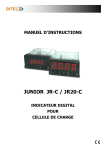
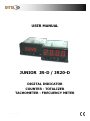
JR-D / JR20-D
USER MANUAL
JUNIOR JR-D / JR20-D
DIGITAL INDICATOR
COUNTER - TOTALIZER
TACHOMETER - FRECUENCY METER
KOSMOS SERIE
www.ditel.es
JR-D / JR20-D
INDEX
GENERAL INFORMATION
Package contents .............................................................................................................................. 4
Recycling instrucctions ....................................................................................................................... 4
General safety considerations .............................................................................................................. 4
Symbols identification ..................................................................................................................... 4
Maintenance ..................................................................................................................................... 5
Warranty .......................................................................................................................................... 5
Conformity declaration ....................................................................................................................... 6
Device description ............................................................................................................................. 7
Dimensions and mounting .................................................................................................................. 7
Display and keyboard ........................................................................................................................ 8
Installing and connecting recommendations ........................................................................................ 8
Connections ...................................................................................................................................... 9
Wiring diagram for MAGNETIC sensor / SWITCH CONTACT input signal ............................................. 9
Wiring diagram for NAMUR sensor input signal ............................................................................... 10
Wiring diagram for NPN, PNP and TTL sensors or 24V DC ENCODER ............................................... 10
High voltage input signal wiring diagram ........................................................................................ 10
Remote counter RESET function wiring diagram ............................................................................. 10
Relays output ............................................................................................................................... 11
INPUT CONFIGURATION
Configuration menu .......................................................................................................................... 12
Input configuration .......................................................................................................................... 12
DISPLAY CONFIGURATION
Display programming .......................................................................................................................
Counter mode (#1) ......................................................................................................................
Tachometer rpm mode (#2) ..........................................................................................................
Tachometer rate mode (#3) ..........................................................................................................
Average measurement maximum time (tMAH) and time limit (tLiM) (tachometer mode only) ............
14
14
15
15
16
SETPOINTS CONFIGURATION
Setpoints configuration .................................................................................................................... 17
Counter mode ('Cont') ................................................................................................................... 17
Tachometer mode ('tACH' y 'rAtE') ................................................................................................. 18
AVAILABLE KEYBOARD FUNCTIONS
TOTALIZER, MAX/MIN and RESET functions ......................................................................................
Counter mode ('Cont') ...................................................................................................................
Tachometer mode ('tACH' y 'rAtE') .................................................................................................
Direct access to Setpoints value .......................................................................................................
Return to default configuration .........................................................................................................
Access to lock-out configuration menu ..............................................................................................
19
19
19
20
20
20
CONFIGURATION LOCK-OUT
Lock-out menu ................................................................................................................................ 21
OUTPUT OPTION
Description .....................................................................................................................................
Function modes description ..............................................................................................................
HI/LO mode activation ..................................................................................................................
Time delay (tachometer mode 'tACH' and 'rAtE' only) .....................................................................
Asymmetrical hysteresis (tachometer mode 'tACH' and 'rAtE' only) ..................................................
1, 2, 3 and 4 control modes (for counter mode 'Cont' and Setpoint 2 only) ......................................
Pulse output "PuLS" (for counter mode 'Cont' only) ........................................................................
Latched output "LAtC" (for counter mode 'Cont' only) .....................................................................
KOSMOS SERIE
www.ditel.es
23
23
23
23
23
24
24
24
2
JR-D / JR20-D
ÍNDICE
Installation ...................................................................................................................................... 25
SPECIFICATIONS
Technical specifications .................................................................................................................... 26
KOSMOS SERIE
www.ditel.es
3
JR-D / JR20-D
GENERAL INFORMATION
This manual does not constitute a contract or a commitment on the part of Diseños y Tecnología, S.A.
All information contained in this document is subject to change without prior notice.
MANUAL VALID FOR INSTRUMENTS WITH D2.00 SOFT VERSION OR HIGHER
Package contents
With the instrument it is also supplied:
Quick installation guide.
Mounting panel accessories (a sealing gasket and 2 fixing clips).
Wiring accessories (plug-in terminal block connectors and 2 key tools for cable insertion).
4 adhesive labels set with engineering units.
Recycling instructions
This electronic instrument is covered by the 2002/96/CE European Directive so, it is properly marked
with the crossed-out wheeled bin symbol that makes reference to the selective collection for electrical and
electronic equipment which indicates that at the end of its lifetime, the final user cannot dispose of it as
unsorted municipal waste.
In order to protect the environment and in agreement with the European legislation regarding waste of
electrical and electronic equipments from products put on the market after 13 August 2005, the user can
give it back, without any cost, to the place where it was acquired to proceed to its controlled treatment and
recycling.
General safety considerations
All instructions and guidelines for the installation and manipulation that are present in this manual must be considered
to ensure personal safety and to prevent damage to either the instrument or any equipment connected to it.
Safety of any equipment incorporated to this instrument is responsibility of the system installer.
If this electronic indicator is used in a manner not specified by the manufacturer in this manual, the protection
provided by the instrument may be impaired.
Symbols identification
WARNING: Potential risk of danger.
Read completely related instructions when this symbol appears in order to know the potential risk and to
know how to avoid it.
WARNING: Risk of electric shock.
Instrument protected by double isolation or reinforced isolation.
KOSMOS SERIE
www.ditel.es
4
JR-D / JR20-D
Maintenance
Instrument repairs should only be carried out by the manufacturer or by its authorized partners.
For frontal device cleaning, just wipe it with a damp cloth and neutral soap product. DO NOT USE SOLVENTS!.
Warranty
All products are warranted against defective material and workmanship for a period of three years from
acquisition date.
If a product appears to have a defect or fails during the normal use within warranty period, please
contact the distributor from whom you purchased the product to be given proper instructions.
This warranty does not apply to defects resulting from action of the customer such as mishandling or
improper interfacing.
The liability under this warranty shall extend only to the repair of the instrument; no responsability is
asumed by the manufacturer for any damage which may result from its use.
All DITEL products benefit from an unlimited and inconditional warranty of three (3) years from the date
of their purchase. Now you can extend this period up to five (5) years from the product commissioning,
only by fulfilling the corresponding form.
Fill up the form in our website at:
http://www.ditel.es/warranty
KOSMOS SERIE
www.ditel.es
5
JR-D / JR20-D
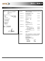
Conformity declaration
Manufacturer: DITEL - Diseños y Tecnología S.A.
Adress:
Xarol, 8C
P.I. Les Guixeres
08915 Badalona.
SPAIN
EN 61326-1
EN 61000-4-2
Electrostatic discharge (ESD)
Air discharge 8kV
Contact discharge 4kV
Criterion B
EN 61000-4-3
Electromagnetic fields
10 V/m
Criterion A
EN 61000-4-4
Fast transients (burst)
Power lines
2 kV
Signal lines
1 kV
Criterion B
EN 61000-4-5
Surge
1 kV L to N
2 kV L,N to Earth
1 kV Signal lines to Earth
Criterion B
EN 61000-4-6
RF conducted interference
3 Vrms
Criterion A
EN 61000-4-11
Voltage dips:
0% V during 1 cycle
40% V during 10/12 cycles
70% V during 25/30 cycles
Short interruptions:
0% V during 250/300 ciclos
Declares, that the product:
Name:
Model:
Specifications:
Digital panel indicator
JR-D / JR20-D
DI 110614
Conforms with Directives:
EMC 2004/108/CE
LVD 2006/95/CE
Applicable standards:
EN61326-1
EN61010-1
Date:
18 December 2012
Signed:
Alicia Alarcia
Charge: Technical Director
Electrical equipment for measurement, control and
laboratory use (EMC)
CISPR11
EN 61010-1
www.ditel.es
Criterion C
Emission limits
Class B
Safety requirements for electrical equipment
for measurement, control an laboratory use.
General safety
Overvoltage category II
Pollution degree 2
Conductive pollution excluded
Isulation type:
Enclosure:
Power/signal:
Power/relays:
Signal/relays:
KOSMOS SERIE
Criterion B
Criterion C
Criterion C
Double
Basic
Double
Double
6
JR-D / JR20-D
Device description
All information contained in this manual, unless indicated, is valid for both JR-D and JR20-D models.
JR-D and JR20-D models from KOSMOS serie are digital indicators fully configurables that allow input type
selection in order to be used as needed. Available signal inputs are the following:
HIGH VOLTAGE (10 to 600V AC)
SENSORS: MAGNETIC, NAMUR, NPN and PNP.
TTL/24V ENCODER
CONTACT SWITCH
The basic instrument consists of a soldered assembly composed of a main board, a display and an input signal
circuits. It can also be incorporated, as an option, an extra plug-in 2 SPDT 8A relays circuit output which is isolated
from signal input and power supply. This extra circuit has independent connectors that are located on the rear part
of the instrument once it is installed.
Both models accept most commonly used pulse generators or transducers to work as an unidirectional counter
or tachometer (rpm or rate). They have configurable factor and offset when are programmed as a counter or
easily scalables directly by frontal keys into desired engineering units working as tachometer (rate). They have 4
digits, configurable decimal point and 2 LED’s for Setpoints status indication. They also provide 8V or 24V DC
outputs for sensors excitation.
JR-D model is provided with 14mm-high digits whereas JR20-D has a larger display of 20mm-high digits that
allows a better reading at longer distance. Both have same maximum display range of 0 to 9999 as a counter and
tachometer and 0 to 999999 as a totalizer (shown in display separately in two parts of three digits each).
Both devices have three frontal keys to interact with internal software and set configuration in order to adapt their
function to particular applications. Device programming runs through some independent menus that show short
messages to easily identify input type and/or display configuration steps.
If relays output option card is installed, once it is recognised by the instrument, activates its own configuration
menu which is only visible under this conditions.
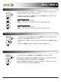
Dimensions and mounting
To install the instrument, prepare a
92x45mm panel cut-out and slide the unit
inwards making sure of placing the sealing
gasket between the front side panel and
the frontal bezel.
While holding the unit in place, put the
fixing clips on both sides of the case and
slide them through the guide tracks until
they reach the panel at the rear side.
Press slightly to fasten the clips to the latching slots
on the case and get the unit fully assembled and
close fitted to achieve a good sealing.
To remove the instrument from the panel, pull outwards the rear fixing
clips latching tabs until they are disengaged, then slide fixing clips back
over the case.
KOSMOS SERIE
www.ditel.es
7
JR-D / JR20-D
Display and keyboard
There are two main function modes:
RUN and PRO. PRO mode is when
configuration menu is entered to
programm the indicator, whereas RUN
is the normal mode in which display
shows the reading according to
configuration and input signal value.
The table below summarizes display
parts description and LEDs and
keyboard function.
2
1
1
3
UP
SHIFT
DATA
2
9
ENTER
4
5
6
RUN MODE
7
8
PRO MODE
1
4 red digit Display
Shows value according configuration.
Shows steps and data during configuration.
2
Minus sign LED (only in JR-D)
(Not used)
(Not used)
3
Keyboard
4
Setpoint 1 LED
It iluminates when Setpoint 1 turns active.
It iluminates when Setpoint 1 turns active.
5
UP key
Main Counter RESET (when pressing more than 3s).
Shows Setpoints value.
Increases value of active digit.
6
SHIFT key
Displays maximum and minimum stored values
(tachometer mode only).
After 3s of pressing, sets maximum and/or minimum
memorized value to current display value
(tachometer mode only).
Shows sequentially totalizer value in two parts, 'H'
and 'L' of 3 digits each (counter mode only).
Totalizer RESET (when pressing more than 3s)
Shifts active digit to the next right digit.
Shows sequentially menu options.
7
DATA/ENTER key
Changes to PRO mode.
Validates selected data and parameters.
Moves one step forward in configuration menu.
Changes to RUN mode.
8
Setpoint 2 LED
It iluminates when Setpoint 2 turns active.
It iluminates when Setpoint 2 turns active.
9
Free space for units label
—
—
—
—
Installing and connecting recommendations
This instrument coforms with the following community directives: EMC 2004/108/CE and LVD 2006/95/CE.
Refer to the instructions in this manual to preserve safety protections.
WARNING: If this instrument is not installed and used in accordance with this instructions,
the protection provided by it against hazards may be impaired.
To meet the requirements of EN 61010-1 standard, where the unit is permanently connected to main
supply, its is obligatory to install a circuit breaking device easy reachable to the operator and clearly
marked as the disconnecting device.
To guarantee electromagnetic compatibility, the following guidelines should be kept in mind:
Power supply wires should be separatedly routed from signal wires and never runned in the same
conduit.
Use shielded cable for signal wiring.
Cables section should be 0.25 mm².
Before connecting signal wires, signal type and input range should be verified to be within the right
limits. Do not connect simultaneously more than one input signal to the meter.
KOSMOS SERIE
www.ditel.es
8
JR-D / JR20-D
Connections
Basic instrument has two rear connectors CN1 and CN2. If 2RE
output option card is installed, two more connectors CN3 and
CN4 appear. See all four connectors location and their pin out in
the right figure. All female provided terminal connectors are of
CAGE CLAMP® technology.
Rear connectors location.
CN4
CN3
1
4
Terminals for CN2 connector admit cables with section from
0.2mm² up to 1.5mm² (AWG 24÷14).
5
2
6
3
CN1
1
Terminals for CN1, CN3 and CN4 connectors admit cables with
section from 0.08mm² up to 2.5mm² (AWG 28÷12).
CN2
2
1 2 3 4 5 6 7
To perform wiring connections, strip the cable leaving from 7 to
10mm exposed to air, insert it in the proper terminal while
pushing down the key insertion tool to open the clip inside the
connector. Release the key tool to fix wire to the terminal.
Proceed in the same way for the rest of terminals. Once all
connections are done, plug connectors to the instrument.
Key tool for cable insertion.
CN1*
CN2
CN4 (relay 2)
CN3 (relay 1)
4
NO
1
NO
1
Phase (AC)
1
-IN (COMMON)
5
CM
2
CM
2
Neutral (AC)
2
+IN
6
NC
3
NC
3
+EXC 8V DC
4
+EXC 24V DC
5
RESET
6
N.C.
7
IN HIGH (10-600V AC)
Notes:
NO: Normally open contact.
CM: Common contact.
NC: Normally closed contact.
* Polarity in CN1 is indistinct for DC power.
WARNING
Isolation:
1500Vrms for 1 minute to signal terminals (CN2) and power terminals (CN1).
2500Vrms for 1 minute to signal terminals (CN2) and relays terminals (CN3 y CN4).
2500Vrms for 1 minute to power terminals (CN1) and relays terminals (CN3 y CN4).
Wiring diagram for MAGNETIC sensor / SWITCH CONTACT input signal
CONNECTION DETAIL
INDICATOR
1
2
SENSOR:
MAGNETIC
CONTACT SWITCH
+IN
-IN (COMMON)
KOSMOS SERIE
www.ditel.es
9
JR-D / JR20-D
Wiring diagram for NAMUR sensor input signal
CONNECTION DETAIL
INDICATOR
2
NAMUR SENSOR
3
+EXC
OUT
+EXC 8V DC
+IN
Wiring diagram for NPN, PNP and TTL sensors or 24V DC ENCODER
CONNECTION DETAIL
INDICATOR
1
2
SENSORS:
NPN/PNP/TTL/
24V DC ENCODER
4
+EXC
OUT
NOTE:
COM.
If an external excitation source is used, its
common terminal must be connected to the
instrument ('-IN (COMMON)' pin 1 of CN2).
+EXC 24V DC
+IN
-IN (COMMON)
High voltage input signal wiring diagram
CONNECTION DETAIL
INDICATOR
1
HIGH VOLTAGE
INPUT
10-600V AC
7
HI
WARNING:
LO
Read recommendations and related data on
pages 8 and 9.
IN HIGH
-IN (COMMON)
Remote counter RESET function wiring diagram
O.C. OUTPUT
INDICATOR
1
CONTACT SWITCH
INDICATOR
1
5
5
RESET
-IN (COMMON)
RESET
-IN (COMMON)
NOTE:
In both cases, main counter RESET is activated through 1 and 5 terminals when contact is closed and it remains
active until the contact is again opened .
Remote totalizer RESET is not available.
KOSMOS SERIE
www.ditel.es
10
JR-D / JR20-D
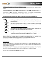
Relays output wiring
RELAY 2
RELAY 1
NO
CM
NC
4
1
5
2
6
3
WARNING:
Read recommendations and related data on pages 8 and 9.
NO
CM
IMPORTANT:
NC
According to EN 61010-1 a protective 8A/250V external
fuse must be installed as a protection against overcurrents.
8A/250V MAX.
KOSMOS SERIE
www.ditel.es
11
JR-D / JR20-D
INPUT CONFIGURATION
Configuration menu
When connecting instrument to Power supply, display test begins automatically to check the good function of LED’s
and digits, once this test is finished, display shows internal software version and then the unit goes to RUN mode.
Configuration software has a hierarchical structure composed of a number of menus and submenus. By pressing
ENTER key, display shows “Pro”, a new pressing brings access to main menu where appear configuration menus,
that is, input configuration (InP), display configuration (dSP) and Setpoints configuration (SEtP). This last menu
only appears if 2RE output option card is installed.
If configuration is totally locked-out, when pressing ENTER key to get into main menu, display shows “dAtA”
instead of “Pro”. This indicates that it is only possible to see programmed information and that it is not allowed to
modifiy any parameter from the entire configuration. In this visualization mode, the instrument automatically
switches back to RUN mode after 15 seconds since last key press.
8888
The instrument provides 3 keys for progressing through the
menus and submenus and for data introducing/modifying:
MAIN MENU
Pro
dAtA
ENTER: Vertical displacement / Validates data.
UP: Increases active digit value.
InP
dSP
SHIFT: Horizontal displacement / Changes active digit.
SEt
Once inside each menu, all configuration parameters are sequentially shown and they can then be introduced or
edited by pressing ENTER key. Numeric values must be entered digit by digit, first selecting digit and then
changing its value. When the display reach desired value, a new ENTER key pressing validates data and routine
goes forward to next configuration step.
Data entered or changes made during configuration are stored in device memory only when programmation
routine belonging to the respective submenu is completed, not before. On last routine step and after having
pressed ENTER key, display indicates “StorE” and the unit goes back again to RUN mode.
Input configuration
The first menu corresponds to input configuration. This, in turn, consists of seven options, one for each input
signal type: (-1-), (-2-), .... (-7-)
SIGNAL TYPE:
-1- : High voltage input (10-600V AC)
InP
-2- : Magnetic sensor
-3- : NAMUR sensor
-1-
-2-
-7-
-4- : PNP sensor
-5- : NPN sensor
-6- : TTL input / 24V DC ENCODER
-7- : Contact switch
KOSMOS SERIE
www.ditel.es
12
JR-D / JR20-D
Cont
tACH
rAtE
OPERATING MODE:
Once input signal type is chosen and ENTER key is pressed, display shows sequentially by pressing repeatedly
SHIFT key the three available operating modes: Counter (Cont), rpm meter (tACH) and rate meter (rAtE).
In counter mode the instrument always counts up the number of pulses received at the input. Totalizer function is
also available as an informative data.
In rpm tachometer mode speed is always displayed in rpm from the especified number of pulses per revolution
given by the sensor.
In rate tachometer mode display scaling is possible from an input value given in pulses per second (input
frequency) to configure a display-frequency ratio reading in engineering units.
For more detailed configuration and operating options, see later on this manual, display and Setpoints
configuration and related available functions.
KOSMOS SERIE
www.ditel.es
13
JR-D / JR20-D
DISPLAY CONFIGURATION
Display Programming
The second menu corresponds to display configuration. This, in turn, consists of a routine that varies depending on
the operating mode previously selected during input configuration. In any case, only the related routine will be
displayed each time.
dSP
#1
#2
dECP
PPr
#3
dir
inV
All display configuration values and
parameters are manually introduced
using frontal keys.
Counter mode (#1)
If selected operating mode is counter (Cont), the displayed routine after pressing ENTER will
be the one on the left.
dECP
First thing to configure is decimal point position. After "dECP" indication, decimal point position
is shown at the right end that means no decimal point. Press SHIFT key several times to
locate decimal point in desired position.
0000.
After pressing again ENTER, "FACt" indication is displayed, configurable factor, and then
"1.000" with first of the four digits flashing. This factor can be programmed from 0.001 to
9.999.
1.000
Display will increase according to the programmed multiplying factor. This factor is set to
"1.000" by default, which makes display match the real number of pulses received at the input.
A factor of 0.010 will increase display one count every 100 pulses at the input whereas a factor
of 2.000 will increase two counts for every pulse at the input.
oFFS
Pressing again ENTER, display shows "oFFS" and then four digits to introduce desired offset
value. Offset can be programmed from 0000 to 9999.
FACt
Offset value is shown on display after every time a main counter RESET is done.
0000
Once offset value is introduced, press ENTER to save changes and to return back to RUN
mode.
OVERFLOW
Simplified main
operation diagram.
counter
OFFSET
DISPLAY
RESET
INPUT
KOSMOS SERIE
www.ditel.es
14
JR-D / JR20-D
Rpm Tachometer (#2)
If selected operating mode is rpm tachometer (tACH), the displayed routine after pressing
ENTER will be the one on the left.
PPr
First thing to configure is the number of pulses per revolution that provides the sensor
connected to the input. After "PPr" indication, display shows four digits (by default 0060) and
the possibility to enter the number that must be between 0001 and 9999.
0060
When pressing ENTER again, display shows "dECP" an then "0000." to locate decimal point
position. It is possible to choose one decimal position or simply no decimal point by pressing
SHIFT key.
dECP
This operating mode always implies a rpm (revolutions per minute) reading and display scaling
it is not available.
0000.
Press again ENTER to save changes and to return back to RUN mode.
Rate Tachometer (#3)
dir
FrEC
1000
If selected operating mode is rate tachometer (rAtE), the displayed
routine after pressing ENTER will be the one on the left.
inV
First thing to configure is the relation between display reading and the number of
pulses per second received at the input (input frequency). If increasing frequency
must result in an increasing display then "dir" (direct proportional variation) must be
selected. Select "inV" (reverse proportional variation) if increasing frequency must
result in a decreasing display or vice-versa. Select desired variation using SHIFT key
an then press ENTER.
1000.
Next action then is to define display scaling in four steps. Display shows "FrEC" and
then the number of pulses per second at the input must be introduced using UP and
SHIFT keys (1000 by default). Press ENTER to accept input frequency value.
diSP
Next step defines decimal point position using SHIFT key. Frequency resolution can
be configured with two (hundredths of a Hertz), one (tenths of a Hertz) or without
decimal places (Hz). Press ENTER to validate decimal point position.
1000
Third step begins with "diSP" message and then a four-digit number which will be the
desired display that will correspond to the input frequency value 'FrEC' previously
configured in first step. Once it is entered (1000 by default) press ENTER to accept.
1000.
Last step defines display decimal point position. Choose desired location using SHIFT
key and press again ENTER to save changes and to return back to RUN mode.
EXAMPLE OF CONFIGURATION:
It is desired to measure the speed in m/s of a conveyor belt which is driven by a shaft turning at 300 rpm that has 20 cm of diameter and
provides 4 pulses per revolution.
In 1 second the shaft will generate 20 pulses (300 rpm = 5 rev/s and each revolution provides 4 pulses). Input frequency is then 20Hz. Belt
lineal speed is 3.142 m/s (v = e/t; v = 5 rev x
x 0.2 m/1 s). The parameters to be configured will be:
Direct proportional variation (dir) ; "FrEC": 0020 ; (no decimal point) ; "diSP": 3142 ; decimal point: 3.142
KOSMOS SERIE
www.ditel.es
15
JR-D / JR20-D
EXAMPLES OF CONFIGURATION OPERATING AS FREQUENCY METER:
It is possible to operate as a frequency meter configuring the instrument as tachometer (rAtE) and scaling display
properly.
For a mains frequency measurement (50Hz), using high voltage input the parameters to configure could be: direct
proportional variation (dir) ; "FrEC": 0500 ; decimal point: 050.0 ; "diSP": 0500 ; decimal point: 050.0
For a frequency of 20kHz measurement, the parameters to configure could be: direct proportional variation
(dir) ; "FrEC": 1000 ; (no decimal point) ; "diSP": 0010 ; decimal point: 001.0
Average measurement maximum time (tMAH) and time limit (tLiM) (tachometer mode only)
The instrument configured as tachometer with parameters properly programmed ("PPr" and
"dCP" for rpm mode and "FrEC" and "diSP" for rate mode) should operate correctly.
However, depending on the sensor type, it may be necessary to modifiy internal
measurement times.
>3s
tMAH
0.1
After defining decimal point position at the end of the two configuration routines for rpm
and rate modes, it is possible to acces the routine that it is shown on the left to modify
"tMAH" and "tLiM" parameters by pressing ENTER for at least 3 seconds.
AVERAGE MEASUREMENT MAXIMUM TIME "tMAH"
tLiM
10
With irregular input signals, display may present fluttering or unwanted variations due that
the number of input cycles detected at each reading are not equal.
"tMAH" parameter allows to extend the average measurement time in seconds to increase
taken signal periods during measurement time, reducing the possibility of display variations.
A value of 0.0 means that no average will be made and every measure will be displayed.
This parameter can be programmed from 0.1 to 9.9 seconds (0.1s by default).
To help stabilizing the display in case of irregular input signals it is recommended to increment this parameter,
taking into account that the display readout will be updated at the programmed time. This parameter can be
reduced, if the input signal is stable at operating frequency, to increment the display refresh rate.
Once tMAH value is entered, press again ENTER to move to the next step.
TIME LIMIT "tLiM"
Time limit, programmable from 1 to 99 seconds (10s by default), allows to limitate waiting time until at least 1
pulse is received at the input before considering it to be 'zero'. If no pulse is detected before programmed time is
elapsed, the display goes to zero.
Decreasing time limit makes instrument be able to respond more quickly to the zero condition when system stops
but, this reduction leads to an increment of the minimum displayable reading before display goes to zero. The
value for this parameter must be always greater or equal to possible minimum period of input signal.
Once tLiM value is entered, press again ENTER to save changes.
KOSMOS SERIE
www.ditel.es
16
JR-D / JR20-D
SETPOINTS CONFIGURATION
Setpoints configuration
The third menu “SEtP” only appears when two relays output card is
installed. For further details on function modes please refer to the
corresponding OUTPUT OPTION part later on this manual.
SEtP
SEt1
Programming steps are similar for both relays on each “SEt1” and
“SEt2” submenus. The parameters to be configured are the following:
SEt2
SETPOINT VALUE:
00.00:
Value entering in counts within available model display
range.
00.00
(Is not possible to change decimal point position, which is
the previously defined in display configuration menu).
Counter mode ('Cont')
CONTROL MODES (FOR SETPOINT 2 ONLY):
ModE
-1-
-4-
Hi
no
PuLS
Lo
nc
LAtC
MODE 1:
INDEPENDENT
MODE 2:
STOP
MODE 3:
RESET
MODE 4:
CLEAR
ACTIVATING MODE:
Hi:
High level relay activation.
Lo:
Low level relay activation.
RESTING CONTACTS STATE:
no:
Normally open contact.
nc:
Normally closed contact.
PULSE OR LATCHED OUTPUT:
PuLS:
01.0
KOSMOS SERIE
LAtC:
Pulse output with activation time configurable from 0.1 to
99.9s.
Latched output.
www.ditel.es
17
JR-D / JR20-D
Tachometer mode ('tACH' and 'rAtE')
Hi
no
dLy
01.0
Lo
nc
HyS
0010
ACTIVATING MODE:
Hi:
High level relay activation.
Lo:
Low level relay activation.
RESTING CONTACTS STATE:
no:
Normally open contact.
nc:
Normally closed contact.
TIME DELAY AND HYSTERESIS:
dLy:
Programmable delay from 0 to 99.9s.
HyS:
Hysteresis in counts within available model display range.
In both counter and tachometer mode, if 2RE output option card is uninstalled, the instrument keeps Setpoints last
configuration in memory, though it can not be visualized.
Thanks to this feature there will be no need to reconfigure relays setting when 2RE output option is again installed
if the same configuration is required.
KOSMOS SERIE
www.ditel.es
18
JR-D / JR20-D
AVAILABLE KEYBOARD FUNCTIONS
In addition to already known functions used to browse through the configuration menus and submenus, introduce
and/or modify existing values and parameters, the instrument provides some more added functions.
TOTALIZER, MAX/MIN and RESET functions
Counter mode ('Cont')
TOTALIZER function is available only when operating as a counter and it is not possible to disable it. It consists in
a 6-digit counter that increases at every received pulse applying the configured factor.
Totalizer value is displayed after indication "tot" when pressing SHIFT key in a sequence of two partial readings of
three digits each. Decimal point is located in the same position as in main counter. The less significant digits are
preceded by a "L" whereas the most significant by a letter "H". If totalizer range is exceded, display will directly
display "OuE". This sequence lasts 15 seconds, alternating low and high readings (if most significant digits are null
they will not be shown). If SHIFT key is not again pressed, the instrument will automatically switch back to RUN
mode after that time.
Main counter RESET function activates only in RUN mode by pressing UP key (or closing contact between 1 and 5
pins of CN2 connector, see page 10) and remains active until this key is released. Main counter RESET sets display
to zero or to configured OFFSET value.
TOTALIZER RESET function activates while visualizing totalizer value, SHIFT key is pressed for at least 3
seconds. After this time zero is displayed. This function always sets totalizer value to zero since there is no
associated OFFSET available for it and does not affect the main counter either.
Tachometer mode ('tACH' and 'rAtE')
This device detects and stores in memory maximum and minimum values reached by the input signal. This values
remain in memory although power supply is removed, as well. When pressing repeatedly SHIFT key, MAX/MIN
function shows saved maximum and minimum values in display since last RESET function activation.
In order to differentiate this values indication from a mode RUN indication, decimal point blinks during the time
these values are shown. The unit automatically switches back to RUN mode after 15 seconds have elapsed since
the last key press.
First SHIFT key pressing shows “MAH” in display followed by the maximum value, a second pressing now shows
“Min” followed by the minimum value and finally, a third pressing shows “run” to back again in an instant to RUN
mode.
MAX/MIN RESET function activates when visualizing maximum or minimum values SHIFT key is pressed for at
least 3 seconds. If maximum is the displayed value, current input signal value will replace the previous maximum
saved value. In the same way, current input signal will replace saved minimum value while is the minimum the
displayed value.
KOSMOS SERIE
www.ditel.es
19
JR-D / JR20-D
Direct access to Setpoints value
Pro
If 2RE output option is installed, it is possible to access to Setpoints value
configuration without having to enter main menu.
SEt1
To access this submenu, from RUN mode and after ENTER key is pressed, simply
press UP key while “Pro” is displayed.
00.00
FIRST SETPOINT VALUE:
SEt2
SEt1:
Setpoint 1 value indication.
00.00:
Value entering in counts within available model display range.
SECOND SETPOINT VALUE:
00.00
SEt2:
Setpoint 2 value indication.
00.00:
Value entering in counts within available model display range.
Return to default configuration
Pro
3s
To access this menu from RUN mode, press ENTER key and while display shows
“Pro” press again ENTER for at least 3 seconds.
00
Display shows now “00” and ‘74’ code must be introduced through SHIFT and UP
keys.
74
Finally press ENTER to validate configuration and back to RUN mode.
Access to lock-out configuration menu
To access this menu from RUN mode, press ENTER key for at least 3 seconds.
8888
3s
CodE
Display shows now “CodE” and then “0000”. Desired security code must be introduced
through SHIFT and UP keys (by default this code is 0000).
0000
Finally press ENTER to begin with lock-out level configuration. If entered security code
is wrong, the instrument will go back to RUN mode.
KOSMOS SERIE
www.ditel.es
20
JR-D / JR20-D
CONFIGURATION LOCK-OUT
Lock-out menu
In order to prevent accidental or indesirable modifications of instrument parameters, a selective or total
configuration lock-out is available. By default the unit is delivered unlocked, giving access to all programming
levels. Once in this menu, the first option will be to choose between lock-out level setting (“LiSt”) or security
access code changing (“CHAn”).
LiSt
CHAn
tLoC
0000
yES
no
If “LiSt” option is selected, display will show momentarily
“tLoc”. Total configuration lock-out is activated by
selecting “yES”, then routine directly jumps to RESET
function and SHIFT key for MAX/MIN function lock-out
configuration before the unit goes back to RUN mode.
When total lock-out is set, no data can be entered
or modified, although it will still be possible to visualize
all programmed parameters. Under these conditions when
entering main menu, initial indication will be “dAtA”
instead of “Pro”.
On the other hand, when “no” option is selected, routine
move on to next step to configure a partial lock-out.
When a partial lock-out is set, only non-locked data
can be entered or modified. Under these conditions
when entering main menu, initial indication will be “Pro”.
SEt1
The following configuration access can be locked-out:
nO
yES
Setpoint 1 configuration (SEt1)
Setpoint 2 configuration (SEt2)
SEt2
Input configuration (InP)
Display configuration (dSP)
nO
yES
RESET function configuration (rSt)
SHIFT key configuration for MAX/MIN function (MAH)
In each case lock-out is activated by selecting “yES” option and
deactivated by selecting “no”.
InP
nO
yES
Setpoints 1 and 2 configuration lock-out is available only when 2RE
output is installed.
RESET function configuration lock-out (rSt) is available only when
operating as counter ('Cont').
dSP
nO
KOSMOS SERIE
SHIFT key for MAX/MIN function configuration lock-out (MAH) is
available only when operating as tachometer ('tACH' or 'rAtE').
yES
If 2RE output option card is uninstalled, the instrument keeps Setpoints
last configuration in memory, though it can not be visualized. There will
be no need to reconfigure Setpoints lock-out when 2RE output option is
again installed if the same configuration is required.
www.ditel.es
21
JR-D / JR20-D
rSt
RESET function activated through UP key can be blocked, as well (only
when operating as counter 'Cont').
nO
NOTE:
Totalizer RESET function lock-out is not available and it will
always remain active.
yES
SHIFT key lock-out for MAX/MIN function is configurable in the same
way as previous configurations (only when operating as tachometer
'tACH' or 'rAtE').
MAH
nO
yES
When lock-out is enabled (selecting “yES”) it is not possible to visualize
maximum or minimum values by pressing SHIFT key, although
instrument internally continues detecting and saving new extreme
values reached by input signal.
Once the instrument programming is completed, if there are parameters that are going to be frequently changed, a
partial lock-out is recommended. A total lock-out is recommended when configuration parameters will be constant
for a long time.
Changing default security code and keep new one in a safe place is also strongly recommended.
KOSMOS SERIE
www.ditel.es
22
JR-D / JR20-D
OUTPUT OPTION
Description
2RE output option allows JR-D and JR20-D models to perform control operations and limit values treatment via
ON/OFF logic outputs. It is supplied as an independent card that is connected to main board without any additional
operation since internal software recognizes it once it is installed. There is no need to read the manual since all
information required is contained in this user manual.
Function modes description
Alarms are independent, they become activate when display value reach Setpoint level programmed by the user
(Setpoints can not be referred to the totalizer). For a correct configuration it will be necessary to define function
mode, as well.
HI/LO mode activation
In HI mode, output activates when display value goes above Setpoint level, whereas in LO mode, output activates
when display value falls below Setpoint level.
Time delay (Tachometer mode 'tACH' and 'rAtE' only)
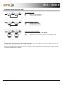
Both output actions can be deferred by a
configurable time delay from 0 up to 99.9 seconds.
Time delay activation starts when display value
reach each Setpoint ‘SET’ either increasingly or
decreasingly, obtaining the ‘dly’ delay in output
activation/deactivation as right figure shows.
Retardo por temporización para OUT1 en modo HI y OUT2 en modo LO
Asymmetrical hysteresis (Tachometer mode 'tACH' and 'rAtE' only)
Both output actions can be deferred by a hysteresis
level which is configurable in counts within full
available display. Decimal point position is the
previously defined in display configuration menu.
Asymmetrical hysteresis action only starts in the
output deactivation edge, obtaining as a result the
‘hys-1’ delay as indicated on the right figure.
Note that outputs activation is not affected by
hysteresis and they activate in each case just when
Setpoint ‘SET’ is reached by display.
KOSMOS SERIE
www.ditel.es
Retardo por histéresis para OUT1 en modo HI y OUT2 en modo LO
23
JR-D / JR20-D
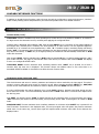
1, 2, 3 and 4 control modes (for counter mode 'Cont' and Setpoint 2 only)
OVER
MODE 1: INDEPENDIENT
Relays will be activated when main counter
reaches their respective Setpoint values. They
will be deactivated when the necessary
conditions are met depending on how output
is configured, 'pulse' or 'latched'. Outputs are
respectively shown overlapped in right
diagrams as
or
.
SETP2
SETP1
OFFSET*
DISPLAY
OUT1*
OUT2*
RESET
MODE 2: STOP
Relay 1 activates when the main counter
reaches its respective Setpoint value and
Relay 2 stops it when Setpoint 2 is reached.
Main counter remains stopped until a RESET
is done. Relays will be deactivated when
display goes down below their respective
Setpoint value.
SETP2
SETP1
OFFSET*
DISPLAY
OUT1*
OUT2*
RESET
MODE 3: RESET
SETP2
Relay 1 activates at its Setpoint value. When
main counter reaches Setpoint 2, a main
counter RESET is done. Relay 2 ouput is pulse
type and remains active for the programmed
time. Relay 1 will be deactivated if display
goes down below Setpoint 1 value.
SETP1
OFFSET*
DISPLAY
OUT1*
OUT2*
RESET
OVER
MODE 4: CLEAR
Relay 1 activates at its Setpoint value. When
main counter reaches Setpoint 2, relay 2
activates and relay 1 is deactivated (if it was
activated). Relay 2 output is latched type.
Main counter goes on until a RESET sets
display to programmed OFFSET value. Relay
2 will be deactivated if display goes below
Setpoint 2.
SETP2
SETP1
OFFSET*
DISPLAY
OUT1*
OUT2*
RESET
* In all cases, the behaviour of OUT1 and OUT2 outputs relays, and consequently of the main counter, changes
depending on defined OFFSET level.
Pulse output "PuLS" (Counter mode only 'Cont') (
)
Relay activates when its Setpoint is reached by display and deactivates after a period of time. This activation time
is a parameter which can be programmed between 0.1s and 9.9s.
Latched output "LAtC" (Counter mode only 'Cont') (
)
Relay activates when its Setpoint is reached by display and remains activated until a RESET makes display go
below that Setpoint.
KOSMOS SERIE
www.ditel.es
24
JR-D / JR20-D
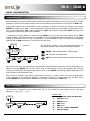
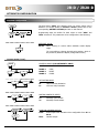
Installation
To physically install the output option, the electronics assembly should be first lifted out from the case. Use a
screwdriver or similar to slightly press both side tabs until the rear case is released. Then broke the junctions from
the corresponding polycarbonate cover in order to obtain the required orifice in the case. This orifice will allow 2RE
connectors come out through instrument rear part once it is installed.
Install 2RE option on the indicated location pushing slightly down until both connectors get perfectly together. For
best installation, it is recommended to solder this card to the main circuit making use of the copper pads on both
sides of its insertion pin and those surrounding the circuit hole where it is inserted in.
Once 2RE is installed, carefully put the circuitry again inside the case verifying that circuits slide properly without
much effort through rear case internal guides.
Each output card is supplied with an adhesive label that indicates wiring connections. To help identifying terminals,
this label should be placed in the upper side of the unit case. Besides its own connections, there are other output
options indications for other outputs that can be installed in other model indicators.
Install 2RE card by plugging
connector in the main circuit.
Input circuit.
To lift out electronics
assembly from the
case, slightly press
both side tabs until
rear case is released.
Display circuit.
When rear case is completely released, junctions
must be broken to remove this polycarbonate cover
to allow 2RE option connectors come out.
Main circuit
Front panel cover
Fix here
connections label
WARNING:
Disconnect all power and rest of input signals
connected to the indicator before installing or
extracting the output option card.
Once 2RE is installed and instrument is again
inside the case, 2RE connectors should come out
through the obtained orifice as this figure shows.
KOSMOS SERIE
www.ditel.es
25
JR-D / JR20-D
SPECIFICATIONS
Technical specifications
SPECIAL FUNCTIONS
Return to factory configuration.
Software configuration lock-out.
TTL/24V encoder
Logic level "0" ........................................................ < 2.4V DC
Logic level "1" ........................................................ > 2.6V DC
PRECISION (tachometer rpm or rate modes)
Temperature coefficient ........................................... 50ppm/ºC
Accuracy .................................................. ±(0.01% rdg + 1d)
Specifications range ................................................ 23ºC±5ºC
Warm-up time ......................................................... 5 minutes
Contact switch
VC ..................................................................................... 5V
RC ............................................................................... 3.9k
ALIMENTACIÓN y FUSIBLES (DIN 41661) (no incorporados)
JR-D:
20-265 V AC 50/60 Hz and 11-265 V DC .. F 3A/ 250V
JR20-D: 20-265 V AC 50/60 Hz and 11-265 V DC .. F 3A/ 250V
Power consumption (both models) ..................................... 3W
Sensor excitation (both models) .... 8V@60mA ; 24V±3V@30mA
DIMENSIONS
Dimensions .................................. 96 x 48 x 60 mm (1/8 DIN).
Panel cutout ........................................................ 92 x 45 mm.
Weight .......................................................................... 150g.
Case material ................................... UL 94 V-0 polycarbonate.
DISPLAY
Ranges:
JR-D ........................................... 0 ÷ 9999, 14mm RED LED
JR20-D ....................................... 0 ÷ 9999, 20mm RED LED
Totalizer (counter mode ) (both models) ............. 0 ÷ 999999
Decimal point........................................................ Configurable
LEDs ........................................ 2 for Setpoints state indication
Display refresh rate
(tachometer rpm or rate modes) .............. 0.1s to 9.9s (config.)
Display/frequency overrange indication .......................... "OuE"
OFFSET (counter mode) ......... Through frontal key configurable
RESET (counter and totalizer) .................... Through frontal key
Remote RESET (counter) ............... Contact switch / Logic input
MAX./MIN. and MAX./MIN. RESET functions
(tachometer rpm or rate modes) ................ Through frontal key
FILTER (switch contact)
Cutoff frequency (Fc) ....................................................... 20Hz
2RE OPTION
Maximum switching current (resistive load) ......................... 8A
Maximum sitching power ................................. 2000VA / 192W
Maximum switching voltage .......................... 400VAC / 125VDC
Contact rating ....................................... 8A @ 250VAC / 24VDC
Contact resistance ............................. 100m at 6V DC @ 1A
Contact type .................................................................. SPDT
Operate time ............................................................... 10ms
NOTE:
In case that the outputs are used to drive inductive
loads, it is recommended to add an RC network between
the coil terminals (preferably) or between the relay
contacts, to limit electromagnetic effects and to extend
contacts life.
ENVIRONMENTAL CONDITIONS
Operating temperature .................................... -10ºC ÷ +60ºC
Storage temperature ....................................... -25ºC ÷ +85ºC
Relative humidity (non-condensing) .................. <95% @ 40ºC
Maximum altitude ........................................................ 2000m
Frontal protection degree ................................................ IP65
INPUT SIGNAL
Maximum frequency (counter mode) ............................. 7.5kHz
Maximum frequency (tachometer rpm or rate modes) ..... 25kHz
Minimum frequency (tachometer rpm or rate modes) ..... 0.01Hz
High voltage input
Range ....................................................... 10V AC to 600V AC
Magnetic sensor
Sensitivity .................................... F ≥ 1kHz ; Vin min. ≥ 100mV
RANGO
RESOLUCIÓN
PRECISIÓN
Namur sensor
±30mV
1µV
±(0.05%L + 6µV)
RC ................................................................................... 1k
ION .........................................................................
< 1mA DC
±300mV
15µV
±(0.05%L + 60µV)
IOFF ......................................................................... > 3mA DC
NPN/PNP sensor
RC ................................................................................... 1k
Logic level "0" ........................................................ < 2.4V DC
Logic level "1" ........................................................ > 2.6V DC
KOSMOS SERIE
www.ditel.es
26
JR-D / JR20-D
NOTES:
INSTRUMENT CONFIGURATION
Use the following template for the annotation of configured parameters in your instrument for later consulting or
data recover.
INPUT:
TYPE:
MODE:
CONT
TACH
DIR
INV
RATE
DISPLAY:
MULT. FACTOR:
OFFSET:
PPR:
DISP. VARIATION:
INPUT FREQUENCY:
DISPLAY:
TMAX.:
TLIM.:
SETPOINTS:
SET1:
ACT. MODE:
DLY / PULSE TIME:
/
HYS / LATCH:
/
no
nc
no
nc
SET2:
CONTROL MODE:
ACT. MODE:
DLY / PULSE TIME:
/
HYS / LATCH:
/
LOCK-OUT:
ACCESS CODE:
KOSMOS SERIE
www.ditel.es
27
JR-D / JR20-D
KOSMOS SERIE
DISEÑOS Y TECNOLOGÍA, S.A.
Tel. +34 933 394 758
Xarol, 8-C P.I. Les Guixeres
Fax +34 934 903 145
www.ditel.es
08915 Badalona (Barcelona)
- Spain.
Email: [email protected] ; web: www.ditel.es
30727439
28
13.09.2013