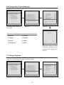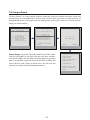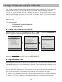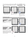
1
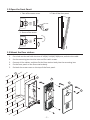
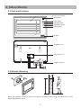
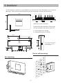
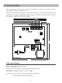
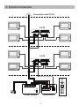
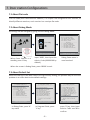
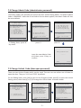
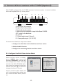
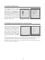
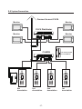
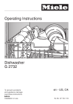
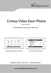
Video Door Entry System
user manual
Use Cat-5 Network Cable
RF CARD
CALL
1
2
3
4
5
6
7
8
9
*
0
#
UNLOCK
TALK/MON
IN-USE
This manual covers MR9L and MR9L/ID Door station
www.intelligenthomeonline.com
PRECAUTIONS
●● Read this manual through before using the product.
●● Slots or openings in the back of the monitor, are provided for ventilation and to
ensure reliable operation of the video monitor or equipment and to protect if
from overheating. These openings must not be blocked or covered. The monitor
should never be placed near or over a radiator or heat register and should not
be placed in a built-in installation such as a bookcase unless proper ventilation
is provided.
●● All parts should be protected from violence vibration. And not allow be
impacting, knocking and dropping.
●● For clean the LCD screen, using hands or wet cloth is forbidden.
●● Please do the cleanness with soft cotton cloth, please do not use the organic or
chemical clean impregnate. If necessary, please use pure water or dilute soap
water to clean the dust.
●● Image distortion may occur if the video door phone is mounted too close to
magnetic field e. g. Microwaves, TV, computer etc.
●● Please keep away the video door monitor from wet, high temperature, dust,
and caustic and oxidation gas in order to avoid any unpredictable damage.
●● Do NOT open the device in any condition, call the administrator for help if there
is any problem or mulfunction happens.
CONTENT
1. Door station - - - - - - - - - - - - - - - - - - - - - - - - - - - - - - - - - - - - - - - - - - 1
2. Indoor Monitor- - - - - - - - - - - - - - - - - - - - - - - - - - - - - - - - - - - - - - - - 3
3. Distributor - - - - - - - - - - - - - - - - - - - - - - - - - - - - - - - - - - - - - - - - - - - 4
4. Power Supply - - - - - - - - - - - - - - - - - - - - - - - - - - - - - - - - - - - - - - - - - 5
5. System Connection- - - - - - - - - - - - - - - - - - - - - - - - - - - - - - - - - - - - - 6
6. Flat Code and Time Setting - - - - - - - - - - - - - - - - - - - - - - - - - - - - - - - 7
7. Door station Configurations- - - - - - - - - - - - - - - - - - - - - - - - - - - - - - - 8
8. Key Fob Settings (only for MR9L/ID)- - - - - - - - - - - - - - - - - - - - - - - - 13
9. Connect 4 Door stations with C5-MDS(Optional) - - - - - - - - - - - - - - 15
10. Specifications - - - - - - - - - - - - - - - - - - - - - - - - - - - - - - - - - - - - - - - 18
1. Door station
Screw cover
Loudspeaker
Camera Lens
Night view LED
LCD screen
ID car window
RF CARD
1
2
3
4
5
6
7
8
9
*
0
#
Digital Keypad
Microphone
1.1 Calling and Unlock Operation
The MR9L Door station is a digital station with 128*128 pixels LCD screen, color CCD
camera, night view LED, and digital keypad.
Visitors can call the apartment by dial the Flat Code (apartment number) on the keypad. If
they don’t know the Flat Code (apartment number), they can search the name list on the
screen. If the door station is in standby, visitors need to press '9#' to display the user name
list. Then, using the '8' / '0' key scroll next/last page. Finally, use the 1 to 7 key to call the
desired flat.
Residents can open the door using their unique Unlock Code (four-digit PIN code). If the
door station is in standby mode, press '#' key, then input the four-digit PIN to open the
door.
-1-
1.2 Open the Front Panel:
1. Take off the screw cover
3. Take off the front panel
2. Screw off the screw
1.3 Mount the Door station:
1. Cut a hole on the wall with the size of 345(H)*115(W)*38(D)mm, and wire the cable.
2. Put the mounting box into the hole and fix it with screws.
3. Connect all the cables, and then fix the Door station body into the mounting box.
4. Fix the front panel on the Door station body.
5. Put back the screw cover on the top of the front panel.
1
2
3
4
5
-2-
2. Indoor Monitor
2.1 Parts and Functions
LCD Touch Screen
Microphone
CALL button
CALL
UNLOCK
UNLOCK button
TALK/MON
TALK/MON button
IN-USE
LED indicator
Speaker
Ventilation Vent
Connection Port
C5-MC connector
145~160 cm
2.2 Monitor Mounting
Wire the system correctly (see Connection chapter) then hang the Monitor on the
Mounting Bracket firmly.
-3-
3. Distributor
The Distributor is used to connect Monitors to the bus line. One Distributor can connect 4
Monitors. There are two mounting measures: bar mounting or dirrect wall mounting.
140mm
P+ P-
Trunk Bus
D
C
B
A
88mm
C5-F4 distributor
A/B/C/D port: Connect to Monitors
Trunk Bus: Bus cable input/output. Connect to last
C5-F4(or doorstation), and connect to next C5-F4
Power
In-use
Data
P-: Power negative input. (Ground)
P+: Power positive input. (15~18V DC)
32mm
36mm
upward
62mm
70mm
HI
13mm
120
set to 120 for the last C5-F4
on the building, the others
must be set to HI.
84mm
Dirrect wall mounting:
Bar mounting:
-4-
4. Power Supply
The system uses a PS-2 power supply. It provides the power for the door station,
distributors, monitors and electric lock.
The maximum numbers of monitors it can support is twenty. If there are more than twenty
monitors in the system an additional power supply is needed. Each extra twenty monitors
will require an additional PS-2 power supply .
ML+, ML- of door station
E-lock (power-off-to-unlock type, 13~16V DC)
P+, P- of the door
station or distributor
E-lock (power-on-to-unlock type, 18V DC)
ON OFF
LK-TEST
SW3
L+ L-
L+ L- ML+ML- P+ P-
AC-IN
UNLOCK
18V-OUT
DC-OUT
SW1
ON
OFF
13~15V-OUT
BAT+
BAT-
AC
AC
PTR1
GND AC
AC
287 mm
VR1
100~240 V AC
247 mm
Cables and distance:
Power supply cable: RVVP 2*1.0 mm2
Distance: from Door station to the last distributor: 600 m Max.
Data Cable: Catalogue-5 cable, 0.5 mm2 or bigger
Distance: from Door station to the last Distributor: 200m Max.
from Distributor to Monitor: 30m Max.
-5-
5. System Connection
Connect to next C5-F4
C5-F4
C5-F4
ML-ML+
L+ L- L+ L- ML+ ML- P+ P+
-
18 V DC lock
RF CARD
ON
P+ P-
SW1
OFF
Power Supply
Doorstation
-6-
1
2
3
4
5
6
7
8
9
*
0
#
6. Flat Code and Time Setting
Every Monitor must be set to a Flat Code, so that
the Door station can identify the Monitor. For
example, if a Monitor is set to a code 0101, when
the visitor press 0101 on the Door station, only the
Monitor with the code 0101 will ring.
alarm
monitor
intercom
setup
exit
1. Power the monitor. Enter into the Main --> setup
--> installation --> (input password: 2412) to open
the configuration page.
H o m e I n t e l l eg e n t S y s t e m
Doorstation Tone
--
01
Camera Tone
--
10
Guard unit Tone
--
05
No Disturb Set
--
off
2. Select and enter Flat Address... item to modify
the flat code.
3. On the installation screen, select Date and Time
Set item to enter the time setting page, use the
touch screen to input the correct Time and Date.
Installation...
Exit
H o m e I n t e l l eg e n t S y s t e m
Password: 0
***
1
2
3
4
5
*
6
7
8
9
0
#
H o m e I n t e l l eg e n t S y s t e m
Alarm in/out delay
--
40
Date and Time set...
Room Address...
Other settings...
Informations...
Exit
H o m e I n t e l l eg e n t S y s t e m
TIME 1 1 : 3 5
DATE 2 0 0 9 1 0 2 1
1
2
3
4
5
*
6
7
8
9
0
#
H o m e I n t e l l eg e n t S y s t e m
-7-
7. Door station Configurations
7.1 About Flat code
The Flat Code (also called monitor address) is a unique code assigned to each monitor, to
identify different monitors; each monitor has a unique flat code.
7.2 About Debug Mode
All settings can be changed by going into the Debug Mode.
> > D E B U G S TAT E < <
--------------------------#-# Program Guide
0-# Redial Last Nbrs
1-# Download from PC
2 - # D e b u g To o l s
[9008]
1
4
7
#
2
5
8
0
3
6
9
*
---------Options---------< > Vo l u m e A d j u s t
< > Auto Dial Back
< > Display Net Data
< ●> D i s p l a y A l a r m
< > Guard Unit Online
---------------------------
System Ready
System Ready
Video Entry System
Video Entry System
When Door Station is in
standby, press '#' key
input '9008', then input the
Admin Code.(66666666 by
default)
Video Entry System
Debug State menu is
now launched
When the screen is Debug State, press '#9009' to exit.
7.3 About Default Set
When the settings of the door station are significantly wrong, the quickest way to solve the
problem is to revert back to the default settings.
> > D E B U G S TAT E < <
--------------------------#-# Program Guide
0-# Redial Last Nbrs
1-# Download from PC
2 - # D e b u g To o l s
---------Options---------< > Vo l u m e A d j u s t
< > Auto Dial Back
< > Display Net Data
< ●> D i s p l a y A l a r m
< > Guard Unit Online
>> Program Guide <<
---------------------------
[1] Configuration
---------------------------
[1]
[2]
[3]
[4]
[5]
[6]
[7]
[8]
[9]
-1.
-2.
-3.
-4.
-5.
-6.
-7.
-8.
-9.
Configuration
Unlock Setting
Monitor Program
Information
Operating Options
Access Security
Card Management
System Maintain
Advanced Config
Net Address [001]
Multi DS Mode [0]
Unlock Timing [1]
Monitoring Nbrs [2]
Intercom Video [1]
Camera Power On [0]
Doorplate Mode [1]
Admin. Code
Default Set
---------------------------
--------------------------Press 1~9 to select
* Back
--------------------------Press 1~9 to select
* Back
Video Entry System
Video Entry System
Video Entry System
In Debug State, press '#'
key twice
In Program Guide, press
'1' key
-8-
press '9' key, then input
Admin Code and'#'to
confirm
7.4 Change Admin Code (administrator password)
The Admin Code is the password to access the door station Debug Mode. The default Admin
Code is '66666666'. Note that if the Default Set has been applied, the Admin Code will also
be set to default.
> > D E B U G S TAT E < <
--------------------------#-# Program Guide
0-# Redial Last Nbrs
1-# Download from PC
2 - # D e b u g To o l s
---------Options---------< > Vo l u m e A d j u s t
< > Auto Dial Back
< > Display Net Data
< ●> D i s p l a y A l a r m
< > Guard Unit Online
>> Program Guide <<
---------------------------
[1] Configuration
---------------------------
[1]
[2]
[3]
[4]
[5]
[6]
[7]
[8]
[9]
-1.
-2.
-3.
-4.
-5.
-6.
-7.
-8.
-9.
Configuration
Unlock Setting
Monitor Program
Information
Operating Options
Access Security
Card Management
System Maintain
Advanced Config
Net Address [001]
Multi DS Mode [0]
Unlock Timing [1]
Monitoring Nbrs [2]
Intercom Video [1]
Camera Power On [0]
Doorplate Mode [1]
Admin. Code
Default Set
---------------------------
--------------------------Press 1~9 to select
* Back
--------------------------Press 1~9 to select
* Back
Video Entry System
Video Entry System
Video Entry System
In Debug State, press '#'
key twice
press '1'
press '8'
>> [1][8]
Change Admin Code
Input the new Admin Code
and then press '#'key to
confirm
--------
<********>
* Back
# Save
Video Entry System
7.5 Change Unlock Code (door open password)
There are two Unlock Codes which can be used. The user can use either one of them to
open the door. They are '1111' and '2222' by default.
On the Debug State, press [# #] to get into the Program Guide, press[2] to open the Unlock
Setting menu, then enter[1] or [2] to change the Unlock Code. as shown below:
> > D E B U G S TAT E < <
--------------------------#-# Program Guide
0-# Redial Last Nbrs
1-# Download from PC
2 - # D e b u g To o l s
---------Options---------< > Vo l u m e A d j u s t
< > Auto Dial Back
< > Display Net Data
< ●> D i s p l a y A l a r m
< > Guard Unit Online
>> Program Guide <<
---------------------------
[2] Unlock Setting
---------------------------
[1]
[2]
[3]
[4]
[5]
[6]
[7]
[8]
[9]
-1.
-2.
-3.
-4.
-5.
-6.
-7.
-8.
Configuration
Unlock Setting
Monitor Program
Information
Operating Options
Access Security
Card Management
System Maintain
Advanced Config
Unlock Code 1 [1111]
Unlock Code 2 [2222]
Code Error Alert [0]
Code Mode [1]
Code Range ...
Code Check ...
Code Nbrs [0]
Change Program Code
---------------------------
--------------------------Press 1~9 to select
* Back
--------------------------Press 1~9 to select...
* Back
Video Entry System
Video Entry System
Video Entry System
-9-
7.6 Change Door station language
> > D E B U G S TAT E < <
--------------------------#-# Program Guide
0-# Redial Last Nbrs
1-# Download from PC
2 - # D e b u g To o l s
---------Options---------< > Vo l u m e A d j u s t
< > Auto Dial Back
< > Display Net Data
< ●> D i s p l a y A l a r m
< > Guard Unit Online
>> Program Guide <<
---------------------------
[9] Advanced Config
---------------------------
[1]
[2]
[3]
[4]
[5]
[6]
[7]
[8]
[9]
-1.
-2.
-3.
-4.
-5.
-6.
-7.
-8.
-9.
Configuration
Unlock Setting
Monitor Program
Information
Operating Options
Access Security
Card Management
System Maintain
Advanced config
To n e S e l e c t
Image Memo
Vo i c e M e m o
Name List
HMC
M o n i t o r Ve r s i o n
Call Mode
L ad nmgi u
A
n a. gCeo d e
Timing
[11]
[0]
[0]
[1]
[0]
[0]
[0]
[1]
---------------------------
--------------------------Press 1~9 to select
* Back
--------------------------Press 1~9 to select
* Back
Video Entry System
Video Entry System
Video Entry System
In Debug State, press '#'
key twice
press '8'
press '9'
>>[9][8]
Language
There are 8 operating languages can be selected:
0. Chinese
4. Spanish
-
1. English
5. German
(0~7)
2. French
6. Italian
3. Portuguese
7. Dutch
* Back
#Save
Video Entry System
Input the number for each
language according to the
language table, press '#' to
confirm.
7.7 Change Ringtone
There are 15 different ringtones, as shown below:
> > D E B U G S TAT E < <
--------------------------#-# Program Guide
0-# Redial Last Nbrs
1-# Download from PC
2 - # D e b u g To o l s
---------Options---------< > Vo l u m e A d j u s t
< > Auto Dial Back
< > Display Net Data
< ●> D i s p l a y A l a r m
< > Guard Unit Online
>> Program Guide <<
---------------------------
[9] Advanced Config
---------------------------
[1]
[2]
[3]
[4]
[5]
[6]
[7]
[8]
[9]
-1.
-2.
-3.
-4.
-5.
-6.
-7.
-8.
-9.
Configuration
Unlock Setting
Monitor Program
Information
Operating Options
Access Security
Card Management
System Maintain
Advanced config
To n e S e l e c t
Image Memo
Vo i c e M e m o
Name List
HMC
M o n i t o r Ve r s i o n
Call Mode
Language
Timing
[11]
[0]
[0]
[1]
[0]
[0]
[0]
[1]
---------------------------
--------------------------Press 1~9 to select
* Back
--------------------------Press 1~9 to select
* Back
Video Entry System
Video Entry System
Video Entry System
-10-
7.8 Name List function
The name list can be edited by using the digital keypad of the door station. The input
method is similar to mobile phones. By default the name list function is ON.
> > D E B U G S TAT E < <
--------------------------#-# Program Guide
0-# Redial Last Nbrs
1-# Download from PC
2 - # D e b u g To o l s
---------Options---------< > Vo l u m e A d j u s t
< > Auto Dial Back
< > Display Net Data
< ●> D i s p l a y A l a r m
< > Guard Unit Online
>> Program Guide <<
---------------------------
[9] Advanced Config
---------------------------
[1]
[2]
[3]
[4]
[5]
[6]
[7]
[8]
[9]
-1.
-2.
-3.
-4.
-5.
-6.
-7.
-8.
-9.
Configuration
Unlock Setting
Monitor Program
Information
Operating Options
Access Security
Card Management
System Maintain
Advanced config
To n e S e l e c t
Image Memo
Vo i c e M e m o
Name List
HMC
M o n i t o r Ve r s i o n
Call Mode
Admin. Code
Timing
[11]
[0]
[0]
[1]
[0]
[0]
[0]
---------------------------
--------------------------Press 1~9 to select
* Back
--------------------------Press 1~9 to select
* Back
Video Entry System
Video Entry System
Video Entry System
To use the namelist function, the Name List item must be set to '1'(enable), which is default.
>>[9][4]
>>[9][4].2 Name List
[Add_008]
Name List
1. Add
2. Modify
-
3. Initialise
Line 1:
_
[
]
Line 2:
[
]
(0~2)
Press 1~3 to select
* Back
#Save
Video Entry System
Press '2#' to enter
* Back
#Save
Video Entry System
Press '1' to add new
names, press '2' to modify
the existing names, press
'3' to initialise to default.
(123)
* Back
#Save
Video Entry System
Flat code and Name
input page.
The first 4 digits are for the Flat Code input (the address of the flat). After 4 digits have
been input, it will switch to Line 1 and the input mode will switch to ABC input mode
automatically. Line 2 is for the names that are too long for one line. After the name has
been input, press '#' to save.
Button 1: Switch the letter between
capitalization and lowercase.
Button 2: A, B, C, (a, b, c)
Button 3: D, E, F, (d, e, f)
Button 4: G, H, I, (g, h, i)
Button 5: J, K, L, (j, k, l)
Button 7: P, Q, R, S, (p, q, r, s)
Button 8: T, U, V, (t, u, v)
Button 9: W, X, Y, Z, (w, x, y, z)
Button * : Cancel
Button 0: Space blank, İ, Ş, Ç, Ü, Ğ, Ö
Button 6: M, N, O, (m, n, o)
-11-
7.9 Using software
“Online Search” is a very useful function that can help the installer to easily check the
connectivity of all the Monitors. Please note, Online does not mean via the internet. In
Debug Mode, press [2 #] to get into the Debug Tools, press [5] to open the “Online Search”
menu, as shown below:
> > D E B U G S TAT E < <
--------------------------#-# Program Guide
0-# Redial Last Nbrs
1-# Download from PC
2 - # D e b u g To o l s
---------Options---------< > Vo l u m e A d j u s t
< > Auto Dial Back
< > Display Net Data
< ●> D i s p l a y A l a r m
< > Guard Unit Online
> > D e b u g To o l s < <
--------------------------[1]
[2]
[3]
[4]
[5]
[6]
[7]
[8]
< > Vo l u m e A d j u s t
< >Auto Dial Back
< >Display Net
< >Display Alarm
Online Searching...
Monitor Property
Vo l t a g e M e a s u r i n g . . .
Simulate Calling...
---------------------------
--------------------------Press 1~8 to select
* Back
Video Entry System
Video Entry System
Search Range: input the Flat Codes and the end Flat codes.
The first two digits of the Flat Code are the floor number;
the last two digits are the Maximum flats quantity on each
floor. For example, input the range from 0101 to 0804, will
search 8 floor and 4 flats on each floor. You will see the
connection status of the selected apartments.
>>Online Searching<<
---------------------------
[----]~[----]
(Search Range)
** BBaacckk
#Search
Video Entry System
>>Online Searching<<
--------------------------[0101] Online
[0102] Online
[0103] Linking Error
[0104] Online
[0201] Online
[0202] Online
[0203] Online
[0204] Linking Error
[0301] Linking Error
** BBaacckk
Video Entry System
-12-
8. Key Fob Settings (only for MR9L/ID)
This chapter explains how to configure the key fob function on MR9L/ID. Please note: for
the Door station without the Key Fob function (the MR9L), keep the settings by default.
The key fob is used to open the lock. Total 500 key fobs can be registered with one Door
station. When swiping the fob on the fob reader on the Door station, the distance must be
less than 3 millimetres.
Key Fobs must be registered on the Door station. Only then can fobs be recognised and
open the door.
To use the key fobs:
1. Enable the ID card/key fob function;
2. Register the Fobs.
8.1 Enable the ID card/key fob function
When the Door station is in standby, press [#] --> [9008] -->Password([66666666 by
default]) to get into the Debug Mode Menu, as shown below.
> > D E B U G S TAT E < <
--------------------------#-# Program Guide
0-# Redial Last Nbrs
1-# Download from PC
2 - # D e b u g To o l s
---------Options---------< > Vo l u m e A d j u s t
< > Auto Dial Back
< > Display Net Data
< ●> D i s p l a y A l a r m
< > Guard Unit Online
>> Program Guide <<
--------------------------[1]
[2]
[3]
[4]
[5]
[6]
[7]
[8]
[9]
Configuration
Unlock Setting
Monitor Program
Information
Operating Options
Access Security
Card Management
System Maintain
Advanced Config
[6] Access Security
--------------------------- 1 . A c c e s s F u n ct itoi onn [[ 1
1 ]]
-2. Passive Address [1]
-3. ACS Address [121]
-4. Clock...
-5. Unlock Verify [0]
---------------------------
--------------------------Press 1~9 to select
* Back
--------------------------Press 1~5 to select
* Back
Video Entry System
Video Entry System
Video Entry System
Press [# #] --> [1] -->[1] to get into the Access Function page and set the value to 1, the
function is now enabled.
Note: the 4. Clock... item is for time setting (which will display on the top of standby
welcome screen, clock function is only available for MR9L/ID).
8.2 Register the Key Fobs
All the registered key fobs are called User Cards/User Key Fobs. New fobs/cards need to be
registered one by one to the Door station to become a User Card/User Key Fob; and every
User Card/User Key Fob is related to a certain Monitor Address (Flat code).
Registered User Cards/Key Fobs can be deleted from the Door station and once unregistered
will not open the door anymore. They can also be re-registered again to become a valid
User Card/User Key Fob. There are two ways to delete User Cards/User Key Fobs:
1. Delete by card: show the unwanted card(s) when the Door station is in Delete Card Mode
2. Delete by Flat Code: will delete all the registered User Cards related to that Flat Code.
-13-
When the Doors tation is standby, press [#] --> [9008] -->Password([66666666 by default])
to get into the Debug Mode Menu, then Press [# #] --> [7] Card Management -->[1] Add
Card to get into the Add Card page as shown below.
>>[7][1]
>>[7][1]
>>[7][1]
Add Card
Add Card
Add Card
[----]
0101
Card:15977131
0101
Card:15977131
Card:15977131
Updated
Updated
Updated
Please input M.Code
* Back
#Save
Video Entry System
Flat Code is asked.
Show the Card
* Back
#Save
Video Entry System
input the flat code
* Back
#Save
Video Entry System
Show the card on the a
Updated will show on
the screen, then show
next card.
8.3 Delete User Cards
Delete by Card/Fob: goto [# #]
Program Guide -->[7] Card
Management --> [2] Delete by
Card, to enter delete by card
page, as shown on the right, then
show the cards you want to delete
one by one.
>>[7][2]
>>[7][2]
Delete By Card
Delete By Card
Sa
h rodw: 1t 5
h9
e 7C7a1r3d1
C
M.Code: 0101
: 13 58 92 74 72 183215 5
CCaar rdd 1
Updated
Updated
Updated
* Back
#Save
Video Entry System
Delete by Flat code: goto [# #]
Program Guide -->[7] Card
Management --> [3] Delete
by M.Code, to enter delete by
flat code page, as shown on the
right, then input the flat code
to which the cards are related,
Updated will show on the screen
if delete successfully. Note that all
registered cards related to the flat
code will be deleted.
>>[7][3]
* Back
#Save
Video Entry System
>>[7][3]
Delete By M.Code
Delete By M.Code
[----]
Card:15977131
0101
Card:15977131
Updated
Updated
Updated
Please input M.Code
* Back
#Save
Video Entry System
-14-
* Back
#Save
Video Entry System
9. Connect 4 Door stations with C5-MDS(Optional)
The C5-MDS is designed for the C5-800 apartment intercom system, to connect multiple
Door stations(Maximum 4) ) in one system.
P+ P-
IN
OUT
D
C
B
A
A: input of the 1st doorstation
B: input of the 2nd doorstation
C: input of the 3rd doorstation
D: input of the 4th doorstation or input of the Slave C5-MDS.
OUT: output for the distributor.
IN: reserved.
P-: Power negative input. (Ground)
P+: Power positive input. (16~18V DC)
To connect the C5-MDS, 3 steps must be done:
1. Configure the Multi Door station Mode for each Door station.
2. Enable the MDS function.
3. Configure the monitoring time for each Door station
9.1 Configure the Multi Door station Mode
When the Door station is standby,
p re s s [ # 8 0 0 1 ] t h e n i n p u t t h e
password [66666666], then you will
see Configuration menu. Press [2]
to enter the Multi DS Mode item,
then input the number for the Door
station and press [#] to save the
change, then press [*] to exit.
[ 1 ] Configuration
---------------------------1 .
-2 .
-3 .
-4 .
-5 .
-6 .
-7 .
-8 .
-9 .
*
Set to 1 in the first door station, set
to 2 in the second door station, set
to 3 in the third door station, and so
on.
Net Address
[ 001 ]
Multi DS Mode
[0]
Unlock Timing
[1 ]
Monitoring Nbrs
[2 ]
Intercom Video
[1]
Camera Power On
[0]
Doorplate Mode
[1]
Change admin code
Default Set
--------------------------Press 1 ~ 9 to select
Back
Video Entry System
-15-
9.2 Enable the MDS function
When the Door station is standby,
press [#8009] on the Door station
keypad, then input the password (the
default password is [66666666]),the
Advanced Configuration screen will
be displayed. Press [5] to enter the
Multi DS Mode item, then input [2]
and press [#] to enable the HMC
function, and the screen will back to
Advanced Config screen.
[9] Advanced Config
---------------------------1. Tone Select[11]
-2. Image Memo [0]
-3. Voice Memo [0]
-4. Name List [1]
-5. HMC [2]
-6. Monitor Version [0]
-7. Call Mode [1]
-8. Language
-9. Timing [30]
--------------------------Press 1~8 to select
*
Back
Video Entry System
9.3 Configure the monitoring time for each door station
When on the Advanced Config screen,
press [5] to enter the HMC item, press
[4] and then press [#] key to enter
the MR-MDS screen. The Addr item is
for the C5-MDS setting, if the current
Door station is connected to the
Master C5-MDS, set the Addr to [1], if
the current Door station is connected
to the Slave C5-MDS, set the Addr to
[2].
>>[9][5].4 MR-MDS
>>[9][5]
HMC
Addr [-]
Ch1T [--]
-
Ch2T [--]
Ch3T [--]
Ch4T [--]
(0..4)
*
Back
# Save
Video Entry System
*
Back
# Save
Video Entry System
The Ch1T, Ch2T, Ch3T and Ch4T is for the monitoring time (seconds)setting for each port. .
If less than 4 door stations connected, set to [0] for the ports that are not used.
Note that all the Door stations which are connected to the same C5-MDS should be have
the same setting on the HMC item.
-16-
9.4 System Connection
Connect to next C5-F4
Monitor
Monitor
C5-F4 Distributor
Monitor
Monitor
C5-MDS
M
S
The switch should
be set to Master
PS2
ON
PP+ SW1
MLOFF
ML+
LL+
LL+
RF CARD
RF CARD
RF CARD
RF CARD
1
2
3
1
2
3
1
2
3
1
2
3
4
5
6
4
5
6
4
5
6
4
5
6
7
8
9
7
8
9
7
8
9
7
8
9
*
0
#
*
0
#
*
0
#
*
0
#
4th
doorstation
3rd
doorstation
-17-
2nd
doorstation
1st
doorstation
10. Specifications
Door station:
●● Power supply: DC 15~18V (supplied by PS2)
●● Camera Lens:
1/3 inch color CCD
●● Power consumption:
Standby 0.5W; Working status 15W
●● Screen:
128*128 pixels LCD
●● Video signal:
1Vp-p, 75Ω, CCIR standard
Distributor:
●● Power supply: ●● Power consumption:
DC 15~18V (supplied by PS2)
Standby 0.3W; Working status 3W
Monitor:
●● Power supply for indoor monitor:
DC 15~18V (supplied by system)
●● Power consumption:
Standby 0.5W; Working status 15W (for kits)
●● Monitor screen:
7 Inch color TFT-LCD
●● Display Resolutions:
1440(R, G, B) x 234 pixels
●● Video signal:
1Vp-p, 75Ω, CCIR standard
●● Wiring:
Cat-5 network cable
-18-
WARRANTY CARD
NB Please keep this document safe, as it is proof of your Warranty
Your Video door system comes with a one year Manufacturers Warranty. When
used normally, the following services are offered:
The following actions will void the Warranty:
1. Damage to the device during installation
2. Damage to the device through misuse
3. Opening and/or disassembling the device
4. Attempting to force the device to perform functions for which it is not intended
5. Attaching the device to power supplies other than thoserecommended by the
manufacturer
Distributor for Warranty purposes:
Intelligent Home Online Ltd
62 Hartley Old Road
Purley, Surrey
CR8 4HJ
+44 (0)20 86170015
www.intelligenthomeonline.com
Product:_____________________________________________
Purchaser Name: ______________________________________
Invoice N: ____________________________________________
Purchase Date_________________________________________
MR9L-CAT5-V2 2015-01-12
The design and specifications can be changed without notice to the user.
Right to interpret and copyright of this manual are preserved.
www.intelligenthomeonline.com