1
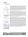
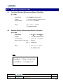
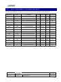
PCTEST ENGINEERING LABORATORY, INC.
6660-B Dobbin Road, Columbia, MD 21045 USA
Tel. 410.290.6652 / Fax 410.290.6554
http://www.pctestlab.com
DECLARATION OF CONFORMITY (DoC)
FCC Part 15B
Manufacturer Name and Address:
Clubbhouse Inventions LLC
6145 Stevens Forest Road
Columbia, MD 21045
Date of Testing:
July 13, 2009
Test Site/Location:
PCTEST Lab, Columbia, MD, USA
Test Report Serial No.:
0907101374
MANUFACTURER:
Clubbhouse Inventions LLC
MODEL:
PB-4
EUT Type:
USB Password Booster
FCC Rule Part(s):
FCC Part 15 Subpart B, Part 2.906
FCC Classification:
FCC Class B Digital Device
Test Procedure:
ANSI C63.4-2003
The device bearing the FCC logo specified above is authorized under the DoC procedure and has been shown to comply
with the applicable technical standards as indicated in the measurement report and has been tested in accordance with the
measurement procedures specified in ANSI C63.4-2003 (See Test Report). These measurements were performed with no
deviation from the standards. Test results reported herein relate only to the item(s) tested.
This test report serves as the responsible party’s requirement to show that the above referenced equipment complies with
the applicable technical standards for the DoC authorization procedure.
I authorize and attest to the accuracy of data. All measurements reported herein were performed by me or were made
under my supervision and are correct to the best of my knowledge and belief. I assume full responsibility for the
completeness of these measurements and vouch for the qualifications of all persons taking them.
NVLAP accreditation does not constitute any product endorsement by NVLAP or any agency of the United States Government. PCTEST
certifies that no party to this application has been denied the FCC benefits pursuant to Section 5301 of the Anti-Drug Abuse Act of 1988,
21 U.S.C. 862.
Model: PB-4
FCC Pt. 15B DECLARATION OF CONFORMITY TEST REPORT
Test Report S/N:
Test Dates:
EUT Type:
0907101374
July 13, 2009
USB Password Booster
© 2009 PCTEST Engineering Laboratory, Inc.
Reviewed by:
Quality Manager
Page 1 of 22
REV 3.2DoC
02/06/09
T A B L E
O F
C O N T E N T S
FCC Class B MEASUREMENT REPORT………………………...……………………………………………….3
1.0
2.0
3.0
4.0
INTRODUCTION ..............................................................................................................................4
1.1
EVALUATION PROCEDURE ................................................................................................................ 4
1.2
SCOPE .................................................................................................................................................. 4
1.3
PCTEST TEST LOCATION ................................................................................................................... 4
PRODUCT INFORMATION..............................................................................................................5
2.1
EQUIPMENT DESCRIPTION ................................................................................................................ 5
2.2
OPERATION MODE.............................................................................................................................. 5
2.3
EMI SUPPRESSION DEVICE(S)/MODIFICATIONS ............................................................................. 5
DESCRIPTION OF TEST.................................................................................................................6
3.1
CONDUCTED EMISSIONS................................................................................................................... 6
3.2
RADIATED EMISSIONS........................................................................................................................ 7
SAMPLE CALCULATIONS ..............................................................................................................8
4.1
CONDUCTED EMISSION MEASUREMENT SAMPLE CALCULATION ............................................... 8
4.2
RADIATED EMISSION MEASUREMENT SAMPLE CALCULATION.................................................... 8
5.0
TEST EQUIPMENT CALIBRATION DATA ......................................................................................9
6.0
ENVIRONMENTAL CONDITIONS .................................................................................................10
7.0
TEST DATA ....................................................................................................................................11
7.1
SUMMARY .......................................................................................................................................... 11
7.2
TEST SUPPORT EQUIPMENT ........................................................................................................... 11
7.3
RADIATED MEASUREMENT DATA ................................................................................................... 12
7.4
LINE CONDUCTED MEASUREMENT DATA ..................................................................................... 13
8.0
CONCLUSION................................................................................................................................15
9.0
TEST SETUP PHOTOGRAPHS ....................................................................................................16
10.0
EUT PHOTOGRAPHS ...................................................................................................................19
11.0
DUTIES OF THE RESPONSIBLE PARTY.....................................................................................20
Model: PB-4
FCC Pt. 15B DECLARATION OF CONFORMITY TEST REPORT
Test Report S/N:
Test Dates:
EUT Type:
0907101374
July 13, 2009
USB Password Booster
© 2009 PCTEST Engineering Laboratory, Inc.
Reviewed by:
Quality Manager
Page 2 of 22
REV 3.2DoC
02/06/09
MEASUREMENT REPORT
FCC Part 15B – Unintentional Radiators
§ 2.1033 General Information
U.S. RESPONSIBLE PARTY: Clubbhouse Inventions LLC
6145 Stevens Forest Road
ADDRESS:
Columbia, MD 21045
TEST SITE:
PCTEST ENGINEERING LABORATORY, INC.
TEST SITE ADDRESS:
6660-B Dobbin Road, Columbia, MD 21045 USA
FCC RULE PART(S):
FCC Part 15 Subpart B, Part 2.906
MODEL:
PB-4
Test Device Serial No.:
N/A
FCC CLASSIFICATION:
FCC Class B Digital Device
DATE(S) OF TEST:
July 13, 2009
Production
Pre-Production
Engineering
Test Methodology
Both conducted and radiated measurements were taken using the methods and procedures described in
ANSI C63.4-2003. Radiated testing was performed at an antenna-to-EUT distance of 3 meters.
Test Facility / NVLAP Accreditation
Conducted and radiated tests were performed at PCTEST Engineering Lab in Columbia, MD 21045,
U.S.A.
•
PCTEST facility is an FCC registered (PCTEST Reg. No. 90864) test facility with the site description
report on file and has met all the requirements specified in Section 2.948 of the FCC Rules and
Industry Canada (IC 2451).
•
PCTEST Lab is accredited by U.S. National Institute of Standards and Technology (NIST) under the
National Voluntary Laboratory Accreditation Program (NVLAP) in EMC, Telecommunication, and
FCC for satisfactory compliance with criteria established in Title 15, Part 285 Code of Federal
Regulations. (NVLAP Lab code: 100431-0).
•
PCTEST Lab is a recognized U.S. Conformity Assessment Body (CAB) in EMC and R&TTE (n.b.
0982) under the U.S.-EU Mutual Recognition Agreement (MRA).
PCTEST TCB is a Telecommunication Certification Body (TCB) accredited to ISO/IEC Guide 65 by
the American National Standards Institute (ANSI) in all scopes of FCC Rules and Industry Canada
Standards (RSS).
PCTEST facility is an IC registered (IC-2451) test laboratory with the site description on file at
Industry Canada.
•
•
Model: PB-4
FCC Pt. 15B DECLARATION OF CONFORMITY TEST REPORT
Test Report S/N:
Test Dates:
EUT Type:
0907101374
July 13, 2009
USB Password Booster
© 2009 PCTEST Engineering Laboratory, Inc.
Reviewed by:
Quality Manager
Page 3 of 22
REV 3.2DoC
02/06/09
1.0
1.1
INTRODUCTION
Evaluation Procedure
The measurement procedure described in the American National Standard for Methods of Measurement of
Radio-Noise Emission from Low-Voltage Electrical and Electronic Equipment in the Range of 9kHz to 40GHz
(ANSI C63.4-2003) was used in the measurement of the Clubbhouse USB Password Booster Model: PB-4.
Deviation from measurement procedure…………………………………………….....................................None
1.2
Scope
Measurement and determination of electromagnetic emissions (EMC) of radio frequency devices including
intentional and/or unintentional radiators for compliance with the technical rules and regulations of the Federal
Communications Commission.
1.3
PCTEST Test Location
The map at the right shows the location of the
PCTEST LABORATORY, its proximity to the FCC
Laboratory, the Columbia vicinity are, the
Baltimore-Washington Internt’l (BWI) airport, the
city of Baltimore and the Washington, DC area.
(see Figure 1-1).
These measurement tests were conducted at the
PCTEST Engineering Laboratory, Inc. facility in
New Concept Business Park, Guilford Industrial
Park, Columbia, Maryland. The site address is
6660-B Dobbin Road, Columbia, MD 21045. The
test site is one of the highest points in the
Columbia area with an elevation of 390 feet above
mean sea level. The site coordinates are 39o
11’15” N latitude and 76o 49’38” W longitude. The
facility is 1.5 miles North of the FCC laboratory,
and the ambient signal and ambient signal
strength are approximately equal to those of the
FCC laboratory.
There are no FM or TV
transmitters within 15 miles of the site. The
detailed description of the measurement facility
was found to be in compliance with the
requirements of § 2.948 according to ANSI C63.42003 on January 27, 2006.
Model: PB-4
Figure 1-1. Map of the Greater Baltimore and
Metropolitan Washington, D.C. area
FCC Pt. 15B DECLARATION OF CONFORMITY TEST REPORT
Test Report S/N:
Test Dates:
EUT Type:
0907101374
July 13, 2009
USB Password Booster
© 2009 PCTEST Engineering Laboratory, Inc.
Reviewed by:
Quality Manager
Page 4 of 22
REV 3.2DoC
02/06/09
2.0
2.1
PRODUCT INFORMATION
Equipment Description
The Equipment Under Test (EUT) is the Clubbhouse USB Password Booster Model: PB-4. The test data
contained in this report pertains only to the emissions due to the digital circuitry of the EUT.
Manufacturer / Model
Description
Clubbhouse / Model: PB-4
USB Password Booster
Table 2-1. EUT Equipment Description
2.2
Operation Mode
The Clubbhouse USB Password Booster Model: PB-4 was tested with a NOTEBOOK connected via USB
interface port. Please see Section 7.0 and the test setup photographs for more information on the test setup.
2.3
EMI Suppression Device(s)/Modifications
No EMI suppression device(s) were added and modifications were made during testing.
Model: PB-4
FCC Pt. 15B DECLARATION OF CONFORMITY TEST REPORT
Test Report S/N:
Test Dates:
EUT Type:
0907101374
July 13, 2009
USB Password Booster
© 2009 PCTEST Engineering Laboratory, Inc.
Reviewed by:
Quality Manager
Page 5 of 22
REV 3.2DoC
02/06/09
3.0
3.1
DESCRIPTION OF TEST
Conducted Emissions
Figure 3-1. Shielded
Enclosure Line-Conducted
Test Facility
Figure 3-2. Line Conducted
Emission Test Set-Up
Figure 3-3. Wooden Table &
Bonded LISNs
The line-conducted facility is located inside a 16’x20’x10’ shielded enclosure,
manufactured by Ray Proof Series 81 (see Figure 3-1). The shielding
effectiveness of the shielded room is in accordance with MIL-Std-285 or NSA
65-5. A 1m x 1.5m wooden table 80cm high is placed 40cm away from the
vertical wall and 1.5m away from the sidewall of the shielded room (see
Figure 3-2). Solar Electronics and EMCO Model 3725/2 (10kHz-30MHz)
50Ω/50μH Line-Impedance Stabilization Networks (LISNs) are bonded to the
shielded room (see Figure 3-3). The EUT is powered from the Solar LISN
and the support equipment is powered from the EMCO LISN. Power to the
LISNs are filtered by a high-current high-insertion loss Ray Proof power line
filter (100dB 14Hz-10GHz). The purpose of the filter is to attenuate ambient
signal interference and this filter is also bonded to the shielded enclosure.
All electrical cables are shielded by braided tinned copper zipper tubing with
an inner diameter of ½”. If the EUT is a DC-powered device, power will be
derived from the source power supply it normally will be powered from and
this supply line(s) will be connected to the Solar LISN. The LISN schematic
diagram is shown (see Figure 3-4). All interconnecting cables more than 1
meter were shortened to a 1 meter length by non-inductive bundling
(serpentine fashion). Sufficient time for the EUT, support equipment, and
test equipment was allowed in order for them to warm up to their normal
operating condition. The RF output of the LISN was connected to the
spectrum analyzer to determine the frequency producing the maximum EME
from the EUT.
The spectrum was scanned from 150kHz to 30MHz with a spectrum
analyzer. The detector function was set to CISPR quasi-peak and average
mode. The bandwidth of the analyzer was set to 10kHz. The EUT, support
equipment, and interconnecting cables were arranged and manipulated to
maximize each EME emission. Each emission was maximized by: switching
power lines; varying the mode of operation or resolution; clock or data
exchange speed; scrolling H pattern to the EUT and/or support equipment,
and powering the monitor from the floor mounted outlet box and the
computer aux AC outlet, if applicable; whichever determined the worst-case
emission. Photographs of the worst-case emission can be seen in the test
setup photographs. Each EME reported was calibrated using the Agilent
E8257D (250kHz – 20GHz) PSG Signal Generator.
Figure 3-4. LISN Schematic
Diagram
Model: PB-4
FCC Pt. 15B DECLARATION OF CONFORMITY TEST REPORT
Test Report S/N:
Test Dates:
EUT Type:
0907101374
July 13, 2009
USB Password Booster
© 2009 PCTEST Engineering Laboratory, Inc.
Reviewed by:
Quality Manager
Page 6 of 22
REV 3.2DoC
02/06/09
3.2
Radiated Emissions
Figure 3-5. 3-Meter Test Site
Figure 3-6. Dimensions of
Outdoor Test Site
Figure 3-7. Turntable and
System Setup
Preliminary measurements were made indoors at 1-meter using broadband
antennas, broadband amplifiers, and spectrum analyzers to determine the
frequency producing the maximum EME. Appropriate precaution was taken to
ensure that all EME from the EUT were maximized and investigated. The
system configuration, clock speed, mode of operation or video resolution, and
turntable azimuth with respect to the antenna was noted for each frequency
found. The spectrum was scanned from 30 to 200 MHz using a bi-conical
antenna and from 200 to 1000 MHz using a log-spiral antenna. Above 1 GHz,
linearly polarized double ridge horn antennas were used.
Final measurements were made outdoors at 3-meter test range using
RobertsTM Dipole antennas or horn antennas (see Figure 3-5). The test
equipment was placed on a wooden and plastic bench situated on a 1.5m x
2m area adjacent to the measurement area (see Figure 3-6). Sufficient time
for the EUT, support equipment, and test equipment was allowed in order for
them to warm up to their normal operating condition. The detector function
was set to CISPR quasi-peak mode and the bandwidth of the spectrum
analyzer was set to 100kHz for frequencies below 1GHz or 1MHz for
frequencies above 1GHz. Above 1GHz the detector function was set to
average mode (RBW = 1MHz, VBW = 10Hz).
The half-wave dipole antenna was tuned to the frequency found during
preliminary radiated measurements. The EUT, support equipment and
interconnecting cables were re-configured to the set-up producing the
maximum emission for the frequency and were placed on top of a 0.8-meter
high non-metallic 1 x 1.5 meter table (see Figure 3-7). The EUT, support
equipment, and interconnecting cables were re-arranged and manipulated to
maximize each EME emission. The turntable containing the system was
rotated and the height of the receive antenna was varied 1 to 4 meters and
stopped at the azimuth and height producing the maximum emission. Each
emission was maximized by: varying the mode of operation or resolution;
clock or data exchange speed; scrolling H pattern to the EUT and/or support
equipment, and powering the monitor from the floor mounted outlet box and
the computer aux AC outlet, if applicable; and changing the polarity of the
antenna, whichever determined the worst-case emission. Photographs of the
worst-case emission can be seen in the test setup photographs. Each EME
reported was calibrated using the Agilent E8257D (250kHz – 20GHz) PSG
Signal Generator. The Theoretical Normalized Site Attenuation Curves for
both horizontal and vertical polarization are shown in Figure 3-8.
Figure 3-8. Normalized Site
Attenuation Curves (H&V)
Model: PB-4
FCC Pt. 15B DECLARATION OF CONFORMITY TEST REPORT
Test Report S/N:
Test Dates:
EUT Type:
0907101374
July 13, 2009
USB Password Booster
© 2009 PCTEST Engineering Laboratory, Inc.
Reviewed by:
Quality Manager
Page 7 of 22
REV 3.2DoC
02/06/09
4.0
4.1
SAMPLE CALCULATIONS
Conducted Emission Measurement Sample Calculation
@ 20.3 MHz
Class B limit
= 60.0 dBμV (Quasi-peak limit)
Reading
= - 57.8 dBm (calibrated quasi-peak level)
Convert to dbμV
= - 57.8 + 107 = 49.2 dBμV
Margin
= 49.2 - 60.0 = - 10.8 dB
= 10.8 dB below limit
4.2
Radiated Emission Measurement Sample Calculation
@ 66.7 MHz
Class B limit
= 100 μV/m = 40.0 dBμV/m
Reading
= - 76.0 dBm (calibrated level)
Convert to dbμV
= - 76.0 + 107 = 31.0 dBμV
Antenna Factor + Cable Loss
= 5.8 dB/m
Total
Margin
= 36.8 dBμV/m
= 36.8 - 40.0 = - 3.2 dB
= 3.2 dB below limit
Note:
Level [dBμV] = 20 log 10 (Level [μV/m])
Level [dBμV] = Level [dBm] + 107
Model: PB-4
FCC Pt. 15B DECLARATION OF CONFORMITY TEST REPORT
Test Report S/N:
Test Dates:
EUT Type:
0907101374
July 13, 2009
USB Password Booster
© 2009 PCTEST Engineering Laboratory, Inc.
Reviewed by:
Quality Manager
Page 8 of 22
REV 3.2DoC
02/06/09
5.0
TEST EQUIPMENT CALIBRATION DATA
Test Equipment Calibration is traceable to the National Institute of Standards and Technology (NIST).
Manufacturer
Model
Description
Cal Date
-
No.165
(30MHz - 1000MHz) RG58 Coax Cable
-
No.166
-
Cal Interval
Cal Due
Serial Number
N/A
N/A
N/A
(1000-26500MHz) Microwave RF Cable
N/A
N/A
N/A
No.167
(100kHz - 100MHz) RG58 Coax Cable
N/A
N/A
N/A
Agilent
11713A
Attenuation/Switch Driver
12/4/2008
12/4/2009
3439A02645
Agilent
8447D
Broadband Amplifier
N/A
N/A
1937A03348
Agilent
8449B
(1-26.5GHz) Pre-Amplifier
12/4/2008
Annual
12/4/2009
3008A00985
Agilent
85650A
Quasi-Peak Adapter
12/4/2008
Annual
12/4/2009
3303A01872
Agilent
8566B
(100Hz-22GHz) Spectrum Analyzer
12/5/2008
Annual
12/5/2009
3638A08713
Agilent
8591A
(9kHz-1.8GHz) Spectrum Analyzer
8/19/2008
Annual
8/19/2009
3144A02458
Agilent
E8257D
(250kHz-20GHz) Signal Generator
3/25/2009
Biennial
3/25/2011
MY45470194
Compliance Design
Roberts
Dipole Set
11/9/2007
Biennial
11/9/2009
146
Compliance Design
Roberts
Dipole Set
11/9/2007
Biennial
11/9/2009
147
Emco
6502
Active Loop Antenna (10k - 30 MHz)
5/15/2009
Biennial
5/15/2011
267
Pasternack
PE7000-6
6 dB Attenuator
N/A
N/A
N/A
Solar Electronics
8012-50-R-24-BNC
LISN
11/8/2007
Biennial
11/8/2009
310233
Sunol
JB5
Bi-Log Antenna (30M - 5GHz)
7/25/2007
Biennial
7/25/2009
A051107
Annual
Table 5-1. Annual Test Equipment Calibration Schedule
Model: PB-4
FCC Pt. 15B DECLARATION OF CONFORMITY TEST REPORT
Test Report S/N:
Test Dates:
EUT Type:
0907101374
July 13, 2009
USB Password Booster
© 2009 PCTEST Engineering Laboratory, Inc.
Reviewed by:
Quality Manager
Page 9 of 22
REV 3.2DoC
02/06/09
6.0
ENVIRONMENTAL CONDITIONS
The temperature is controlled within range of 15oC to 35oC.
The relative humidity is controlled within range of 10% to 75%.
The atmospheric pressure is controlled within the range 86-106kPa (860-1060mbar).
Model: PB-4
FCC Pt. 15B DECLARATION OF CONFORMITY TEST REPORT
Test Report S/N:
Test Dates:
EUT Type:
0907101374
July 13, 2009
USB Password Booster
© 2009 PCTEST Engineering Laboratory, Inc.
Reviewed by:
Quality Manager
Page 10 of 22
REV 3.2DoC
02/06/09
7.0
7.1
TEST DATA
Summary
Test Date(s):
July 13, 2009
Test Engineer:
FCC Part 15 Section
Description
Result
15.107
Conducted Emissions
PASS
15.109
Radiated Emissions
PASS
Table 7-1. Summary of Test Results
7.2
Test Support Equipment
1 Panasonic Toughbook #2
w/ Panasonic AC Adapter
FCC ID: ACJ9TGCF-513
S/N: 7ATYA28277R
Model: CF-AA1683A
S/N: 1683AM306Y01583D
2.0m
Unshielded AC power cord
2.0m
Unshielded DC power cord with ferrite bead
on notebook end
2 Dynex USB PC Camera
Model: DX-WC101 (DoC)
2.07m Shielded USB Cable
Note:
Model: PB-4
S/N: 122D05AC
See test setup photographs for actual system test setup.
FCC Pt. 15B DECLARATION OF CONFORMITY TEST REPORT
Test Report S/N:
Test Dates:
EUT Type:
0907101374
July 13, 2009
USB Password Booster
© 2009 PCTEST Engineering Laboratory, Inc.
Reviewed by:
Quality Manager
Page 11 of 22
REV 3.2DoC
02/06/09
7.3
Radiated Measurement Data
§15.109; RSS-Gen (6(a))
Frequency
[MHz]
Level
[dBm]
AFCL
[dB]
Pol
[H/V]
Height
[m]
Azimuth
[degrees]
Field
Strength
[dBμV/m]
Limit
[dBμV/m]
Margin
[dB]
78.12
-94.37
10.91
H
1.5
153
23.54
40.00
-16.46
124.95
-98.11
13.12
H
1.4
351
22.01
43.52
-21.51
167.37
-96.55
14.39
H
1.0
120
24.84
43.52
-18.68
215.11
-95.27
14.34
H
1.3
42
26.06
43.52
-17.46
249.67
-96.94
13.88
V
2.2
312
23.94
46.02
-22.08
304.65
-95.51
16.29
H
1.2
221
27.78
46.02
-18.24
Table 7-2. Radiated Measurements at 3-meters
NOTES:
1. All modes of operation were investigated and the worst-case
emissions are reported.
2. Radiated Emissions were measured from 30MHz – 2000MHz.
3. The radiated limits are shown on Figure 7-1. Above 1GHz the
limit is 500μV/m.
Figure 7-1. 3 Meter Limits
_____________________
1.
All readings are calibrated by Agilent E8257D (250kHz – 20GHz) PSG Signal Generator with accuracy traceable
to the National Institute of Standards and Technology (NIST).
2.
AFCL = Antenna Factor (Roberts dipole) and Cable Loss (30 ft. RG58C/U).
3.
Measurements made using CISPR quasi-peak mode. Above 1GHz, peak detector function mode is used with a
resolution bandwidth of 1MHz and a video bandwidth of 1MHz. The peak level complies with the average limit.
Peak mode is used with linearly polarized horn antenna and low-loss microwave cable.
Model: PB-4
FCC Pt. 15B DECLARATION OF CONFORMITY TEST REPORT
Test Report S/N:
Test Dates:
EUT Type:
0907101374
July 13, 2009
USB Password Booster
© 2009 PCTEST Engineering Laboratory, Inc.
Reviewed by:
Quality Manager
Page 12 of 22
REV 3.2DoC
02/06/09
7.4
Line Conducted Measurement Data
§15.107; RSS-Gen (7.2.2)
PCTEST Engineering Laboratory Inc.
Company : Clubbhouse Inventions LLC
Model Number : PB-4
Standard : FCC Part 15B class B
Power Source : AC120V/60Hz
Tested Date : 07/13/2009
Note : None
Conducted Emission Measurement
90.00
Line A
80.00
Line B
QP Limit
Av Limit
Emission Level [dBµV]
70.00
60.00
50.00
40.00
30.00
20.00
10.00
0.00
0.1000
1.0000
10.0000
100.0000
Frequency [MHz]
Ver.1.1 ©PCTEST 2006.08
Plot 7-1. Line-Conducted Test Plot
Notes:
1.
All Modes of operation were investigated and the worst-case emissions are reported.
2.
The limit for Class B device(s) from 150kHz to 30MHz are specified in Section 15.107 of the Title 47 CFR.
3.
Line A = Phase; Line B = Neutral
4.
Traces shown in plot are made using a peak detector.
5.
Deviations to the Specifications:
Model: PB-4
None.
FCC Pt. 15B DECLARATION OF CONFORMITY TEST REPORT
Test Report S/N:
Test Dates:
EUT Type:
0907101374
July 13, 2009
USB Password Booster
© 2009 PCTEST Engineering Laboratory, Inc.
Reviewed by:
Quality Manager
Page 13 of 22
REV 3.2DoC
02/06/09
Line Conducted Measurement Data (Cont’d)
§15.107; RSS-Gen (7.2.2)
No.
Line
1
2
3
4
5
6
7
8
9
10
11
12
13
14
15
16
17
18
19
20
A
A
A
A
A
A
A
A
A
A
B
B
B
B
B
B
B
B
B
B
Frequency
Factor
QP
Limit
Margin
Average
Limit
Margin
[MHz]
[dB]
[dBµV]
[dBµV]
[dB]
[dBµV]
[dBµV]
[dB]
0.150
0.151
0.181
0.182
0.194
0.240
0.289
0.300
8.787
9.143
0.150
0.155
0.184
0.192
0.240
0.241
0.255
0.300
0.310
0.419
8.20
8.20
8.02
8.02
7.96
7.78
7.61
7.57
7.58
7.59
8.20
8.20
8.01
7.97
7.79
7.78
7.73
7.57
7.56
7.48
46.62
44.77
47.35
47.63
38.07
40.77
32.68
32.57
31.23
30.29
45.16
47.22
47.85
38.74
40.20
40.84
32.50
32.49
28.63
25.50
66.00
66.00
64.44
64.40
63.85
62.08
60.56
60.26
60.00
60.00
66.00
66.00
64.32
63.97
62.09
62.08
61.58
60.24
59.98
57.47
-19.38
-21.23
-17.09
-16.77
-25.78
-21.31
-27.88
-27.69
-28.77
-29.71
-20.84
-18.78
-16.47
-25.23
-21.89
-21.24
-29.08
-27.75
-31.35
-31.97
35.04
34.04
38.57
37.83
27.61
32.73
21.72
22.74
20.71
20.69
32.83
34.98
37.78
27.41
26.50
31.80
22.66
24.18
20.37
19.33
56.00
56.00
54.44
54.40
53.85
52.08
50.56
50.26
50.00
50.00
56.00
56.00
54.32
53.97
52.09
52.08
51.58
50.24
49.98
47.47
-20.96
-21.96
-15.87
-16.57
-26.24
-19.35
-28.84
-27.52
-29.29
-29.31
-23.17
-21.02
-16.54
-26.56
-25.59
-20.28
-28.92
-26.06
-29.61
-28.14
Table 7-3. Line-Conducted Test Data
Notes:
1.
All Modes of operation were investigated and the worst-case emissions are reported.
2.
The limit for Class B device(s) from 150kHz to 30MHz are specified in Section 15.107 of the Title 47 CFR.
3.
Line A = Phase; Line B = Neutral
4.
Traces shown in plot are made using a peak detector.
5.
Deviations to the Specifications:
Model: PB-4
None.
FCC Pt. 15B DECLARATION OF CONFORMITY TEST REPORT
Test Report S/N:
Test Dates:
EUT Type:
0907101374
July 13, 2009
USB Password Booster
© 2009 PCTEST Engineering Laboratory, Inc.
Reviewed by:
Quality Manager
Page 14 of 22
REV 3.2DoC
02/06/09
8.0
CONCLUSION
The data collected relate only to the item(s) tested and show that the Clubbhouse USB Password Booster
Model: PB-4 has been tested to comply with the requirements specified in Part 15 (§15.107 and §15.109)
and Part 2 of the FCC Rules under the Declaration of Conformity authorization procedures.
Model: PB-4
FCC Pt. 15B DECLARATION OF CONFORMITY TEST REPORT
Test Report S/N:
Test Dates:
EUT Type:
0907101374
July 13, 2009
USB Password Booster
© 2009 PCTEST Engineering Laboratory, Inc.
Reviewed by:
Quality Manager
Page 15 of 22
REV 3.2DoC
02/06/09
9.0
TEST SETUP PHOTOGRAPHS
Model: PB-4
FCC Pt. 15B DECLARATION OF CONFORMITY TEST REPORT
Test Report S/N:
Test Dates:
EUT Type:
0907101374
July 13, 2009
USB Password Booster
© 2009 PCTEST Engineering Laboratory, Inc.
Reviewed by:
Quality Manager
Page 16 of 22
REV 3.2DoC
02/06/09
Model: PB-4
FCC Pt. 15B DECLARATION OF CONFORMITY TEST REPORT
Test Report S/N:
Test Dates:
EUT Type:
0907101374
July 13, 2009
USB Password Booster
© 2009 PCTEST Engineering Laboratory, Inc.
Reviewed by:
Quality Manager
Page 17 of 22
REV 3.2DoC
02/06/09
Model: PB-4
FCC Pt. 15B DECLARATION OF CONFORMITY TEST REPORT
Test Report S/N:
Test Dates:
EUT Type:
0907101374
July 13, 2009
USB Password Booster
© 2009 PCTEST Engineering Laboratory, Inc.
Reviewed by:
Quality Manager
Page 18 of 22
REV 3.2DoC
02/06/09
10.0
EUT PHOTOGRAPHS
Model: PB-4
FCC Pt. 15B DECLARATION OF CONFORMITY TEST REPORT
Test Report S/N:
Test Dates:
EUT Type:
0907101374
July 13, 2009
USB Password Booster
© 2009 PCTEST Engineering Laboratory, Inc.
Reviewed by:
Quality Manager
Page 19 of 22
REV 3.2DoC
02/06/09
11.0
DUTIES OF THE RESPONSIBLE PARTY
Declaration of Conformity: Responsible Party and Labeling Information:
As required by §2.906 of the FCC Rules and Regulations, authorization under the Declaration of Conformity
procedure requires that the responsible party make measurements or take other necessary steps to ensure
that the equipment complies with the appropriate technical standards.
The Declaration of Conformity attaches to all items subsequently marketed by the responsible party which are
identical to the sample tested and found acceptable by the responsible party.
As defined in §2.909 the responsible party of equipment subject to authorization under the Declaration of
Conformity procedure is:
(1) The manufacturer or, if the equipment is assembled from individual component parts and the
resulting system is subject to authorization under a Declaration of Conformity, the assembler.
(2) If the equipment, by itself, is subject to a Declaration of Conformity and that equipment is imported,
the importer.
(3) Retailers or original equipment manufacturers may enter into an agreement with the responsible
party designated in paragraph (c)(1) or (c)(2) of this section to assume the responsibilities to ensure
compliance of equipment and become the new responsible party.
(4) If the radio frequency equipment is modified by any party not working under the authority of the
responsible party, the party performing the modifications, if located within the U.S., or the importer, if
the equipment is imported subsequent to the modifications, becomes the new responsible party.
Under §2.1073 of the FCC Rules the Declaration of Conformity signifies that the responsible party, as defined
above, has determined that the equipment has been shown to comply with the applicable technical standards
if no unauthorized change is made in the equipment and if the equipment is properly maintained and operated.
Compliance with these standards shall not be construed to be a finding by the responsible party with respect
to matters not encompassed by the Commission's rules.
A Declaration of Conformity by the responsible party is effective until a termination date is otherwise
established by the Commission.
No person shall, in any advertising matter, brochure, etc., use or make reference to a Declaration of
Conformity in a deceptive or misleading manner or convey the impression that such a Declaration of
Conformity reflects more than a determination by the responsible party that the device or product has been
shown to be capable of complying with the applicable technical standards of the Commission's rules.
Labeling and Identification Requirements:
Per §2.1074 of the FCC Rules, devices subject to a Declaration of Conformity shall be uniquely identified by
the responsible party. This identification shall not be of a format which could be confused with the FCC
Identifier required on certified, notified, type accepted or type approved equipment. The responsible party shall
maintain adequate identification records to facilitate positive identification for each device.
Model: PB-4
FCC Pt. 15B DECLARATION OF CONFORMITY TEST REPORT
Test Report S/N:
Test Dates:
EUT Type:
0907101374
July 13, 2009
USB Password Booster
© 2009 PCTEST Engineering Laboratory, Inc.
Reviewed by:
Quality Manager
Page 20 of 22
REV 3.2DoC
02/06/09
The following Compliance information is required per § 2.1077 for devices authorized under the Declaration of
Conformity Procedure.
If a product is tested and authorized under a Declaration of Conformity, a compliance information
statement shall be supplied with the product at the time of marketing or importation containing the
following information:
(1) Identification of the product, e.g., name and model number;
(2) A statement, similar to that contained in §15.19(a)(3) of this chapter (see below), that the product
complies with part 15 of this chapters; and
(3) The identification, by name, address and telephone number, of the responsible party, as defined in
§2.909. The responsible party for a Declaration of Conformity must be located within the United
States.
The compliance information statement shall be included in the user's manual or as a separate sheet.
In cases where the manual is provided only in a form other than paper, such as on a computer disk or
over the Internet, the information required by this section may be included in the manual in that
alternative form, provided the user can reasonably be expected to have the capability to access
information in that form.
Labeling Requirements:
Products subject to authorization under a Declaration of Conformity shall be labeled as follows:
The label shall be located in a conspicuous location on the device and shall contain the unique
identification described in §2.1074 of the FCC Rules and the following logo:
If the product is authorized based on testing of the product or system; or
If a personal computer is authorized based on assembly using separately authorized components, in
accordance with §15.101(c)(2) or (c)(3), and the resulting product is not separately tested:
Label text and information should be in a size of type large enough to be readily legible, consistent with the
dimensions of the equipment and the label. However, the type size for the text is not required to be larger
than eight-point.
Model: PB-4
FCC Pt. 15B DECLARATION OF CONFORMITY TEST REPORT
Test Report S/N:
Test Dates:
EUT Type:
0907101374
July 13, 2009
USB Password Booster
© 2009 PCTEST Engineering Laboratory, Inc.
Reviewed by:
Quality Manager
Page 21 of 22
REV 3.2DoC
02/06/09
When the device is so small or for such use that it is not practicable to place the statement specified under
paragraph §15.19(b)(1) of this section on it, such as for a CPU board or a plug-in circuit board peripheral
device, the text associated with the logo may be placed in a prominent location in the instruction manual or
pamphlet supplied to the user. However, the unique identification (trade name and model number) and the
logo must be displayed on the device.
The label shall not be a stick-on, paper label. The label shall be permanently affixed to the product and shall
be readily visible to the purchaser at the time of purchase, as described in §2.925(d). “Permanently affixed”
means that the label is etched, engraved, stamped, silk-screened, indelibly printed, or otherwise permanently
marked on a permanently attached part of the equipment or on a nameplate of metal, plastic, or other material
fastened to the equipment by welding, riveting, or a permanent adhesive. The label must be designed to last
the expected lifetime of the equipment in the environment in which the equipment may be operated and must
not be readily detachable.
Information to the User:
Per the requirements of §15.21 of the FCC Rules the following information must be provided to the end user.
The user’s manual or instruction manual shall caution the user that changes or modifications not expressly
approved by the party responsible for compliance could void the user's authority to operate the equipment. In
cases where the manual is provided only in a form other than paper, such as on a computer disk or over the
Internet, the information required by this section may be included in the manual in that alternative form,
provided the user can reasonably be expected to have the capability to access information in that form.
Additionally per §15.105 for a Class B digital device or peripheral, the instructions furnished the user shall
include the following or similar statement, placed in a prominent location in the text of the manual:
Note: This equipment has been tested and found to comply with the limits for a Class B digital device,
pursuant to part 15 of the FCC Rules. These limits are designed to provide reasonable protection against
harmful interference in a residential installation. This equipment generates, uses, and can radiate radio
frequency energy and, if not installed and used in accordance with the instructions, may cause harmful
interference to radio communications. However, there is no guarantee that interference will not occur in a
particular installation. If this equipment does cause harmful interference to radio or television reception, which
can be determined by turning the equipment off and on, the user is encouraged to try to correct the
interference by one or more of the following measures:
—Reorient or relocate the receiving antenna.
—Increase the separation between the equipment and receiver.
—Connect the equipment into an outlet on a circuit different from that to which the receiver is connected.
—Consult the dealer or an experienced radio/TV technician for help.
Model: PB-4
FCC Pt. 15B DECLARATION OF CONFORMITY TEST REPORT
Test Report S/N:
Test Dates:
EUT Type:
0907101374
July 13, 2009
USB Password Booster
© 2009 PCTEST Engineering Laboratory, Inc.
Reviewed by:
Quality Manager
Page 22 of 22
REV 3.2DoC
02/06/09
1
DECLARATION OF CONFORMITY
This device complies with Part 15 of the FCC Rules. Operation is subject to the following
two conditions: (1) This device may not cause harmful interference, and (2) This device
must accept any interference received, including interference that may cause undesired
operation.
Model:
PB-4
Trade Name:
Clubbhouse
U.S. Responsible Party: Clubbhouse Inventions LLC
Address:
6145 Stevens Forest Road
Columbia, MD 21045
Tel. No.: 443.538.1426
SUMMARY:
Trade Name/Model:
Clubbhouse / PB-4
Equipment EUT Type:
USB Password Booster
FCC Rule Part(s):
FCC Part 15 Subpart B, Part 2.906
FCC Classification:
FCC Class B Digital Device
Manufacturer:
Clubbhouse Inventions LLC
Address:
6145 Stevens Forest Road
Columbia, MD 21045
We hereby declare that the equipment bearing the trade name and model number specified above was
tested conforming to the applicable FCC Rules under the most accurate measurement standards
possible, and that all the necessary steps have been taken and are in force to assure that production
units of the same equipment will continue to comply with the Commission’s requirements.
Clubbhouse Inventions LLC
Signature
© 2009 PCTEST Engineering Laboratory, Inc.
Date
1