1
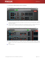
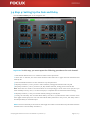
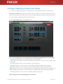
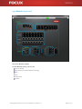
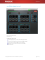
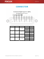
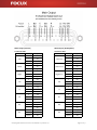
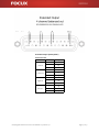
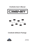
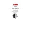
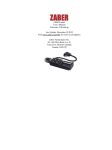
 CM24 Digital Cinema Processor User Manual 2013 Version 4.2 CM24 Digital Cinema Processor User Manual 2013 Version 4.2 Page 1 of 31 Welcome to your CM24 Touch Screen Control Connection status Device name Output volume display Input volume display Input selection buttons (Push up) Surround mode switch (Push up) Main volume fader Mute button (Pull to the right) Front Panel Power indicator LED Power switch AC input Ethernet Port Relay output (unavailable now) Logic input (unavailable now) Rear Panel Extended output (Ch 9~12) Main output (Ch 1~8) 8‐Channel analog input Microphone input Aux input Non‐sync input (L and R) 4X AES input CM24 Digital Cinema Processor User Manual 2013 Version 4.2 Page 2 of 31 Contents Chapter 1: Ready 4 What is in the Box 4 Tools You Need to Prepare by you Chapter 2: Setting Up Your CM24 5 Installing Hardware and Software Chapter 3: Starting Tuning 6 Running CM24 Control Software 7 Connecting the Processor 9 Setting up the Crossover Control Panel 10 Setting up the Screen Channel Speaker 12 Optimizing the Subwoofer and Surround Speakers 13 Adjusting the Phase of Each Channel (optional) 14 Setting up the Gain and Delay 15 Room Equalization 16 Adjusting the Parametric Equalizer Panel 17 Adjusting the Graphic Equalizer Panel 18 Adjusting Output Level Finally 19 Others 19 Aux Input (optional) 20 Monitor (optional) 21 PEQ for Output (optional) 22 Backup and Restore 22 Saving Settings in a Configuration File 22 Loading a Saved Configuration File 23 Network Settings 23 Remote Control by TMS 23 Configuring the IP Settings of Your Touch Pad 24 Technical Specifications 25 CONNECTOR 29 DISCLAIMER OF WARRANTIES AND LIMITATION OF LIABILITY 30 IMPORTANT SAFETY INSTRUCTIONS CM24 Digital Cinema Processor User Manual 2013 Version 4.2 Page 3 of 31 Chapter 1: Ready Your CM24 is designed so you can easily set it up and start using it right away. If you have never used CM24, read this chapter for instructions about getting started. Important: Read all the setup instructions in this chapter and the safety information starting on page 30 before you plug your CM24 into a power outlet. If you are an experienced user, you may already know enough to get started. Make sure you look over the information in Chapter 3, “Starting Tuning,” to find out about the new features of your CM24. 1.1 What is in the Box Your CM24 comes with one cinema processor CM24, one 7'' touch screen, one mount hardware for touch screen, one wireless access point, one CD (incl. manual , software), wiring and cables. 1.2 Tools You Need to Prepare by Yourself Computer: built‐in network, and installed with Microsoft Windows XP, Windows Vista, Windows 7 or Windows 8. RTA: any types of real‐time analyzer. Microphone: a straight frequency response curve is required if possible. Microphone stand: any suitable types. Signal cable: any suitable types. CM24 Digital Cinema Processor User Manual 2013 Version 4.2 Page 4 of 31 Chapter 2: Setting Up Your CM24 Follow these steps to set up your CM24. Step 1: Connecting the Wireless Access Point to Your Processor Connect the network cable from an ETHERNET port on your CM24 processor to one of the LAN ports on the wireless access point. Then plug the power cords of both into the power outlet. Step 2: Press the power button at the back to turn on your CM24 processor. Turn on the wireless access point. Then press the power button on the top to turn on your wireless touch pad. To recharge the touch pad, plug the MiniUSB charger cord into the touch pad. Step 3: Connecting the processor to the wireless touch pad Press and hold the red dot in the upper right corner of the touch screen, and drag it to the left; a pop‐up window appears with a list of processors to allow you to select your processor. Then select the processor you want to connect. After a successful connection, the red dot turns green. Step 4: Installing the software System Requirements The CM24 setup software runs on Microsoft Windows XP, Windows Vista, Windows 7 or Windows 8. . NET Framework 3.5 or the newest version is required. If your computer does not have .NET Framework 3.5, but your computer is already connected to the Internet, then you can begin to install CM24 control software. The installation program will be automatically downloaded and install .NET Framework 3.5 for your computer. Installation Put the installation CD into your CD drive on your computer or download the software from www.focux.us, open the FocuxPanel folder, double‐click setup to start the installation and follow the instructions to complete the installation. When the installation procedure finishes, the software will start immediately. Important: CM24 control software cannot run without network. So if your computer does not have any network, or network is disabled, or the network is enabled but it is not connected to any network, then the software is just installed, but still cannot run. Any time you want to run CM24 control software, your computer must be connected to a network (for example CM24 processors, wireless access points, routers, Internet or any other network). CM24 Digital Cinema Processor User Manual 2013 Version 4.2 Page 5 of 31 Chapter 3: Starting Tuning Important: Before starting, check all equipments thoroughly, including speakers, amplifiers, power supplies, signal cables and speaker cables, make sure the connections of all the equipments are correct and firm. Check the noise of the air‐conditioning, and try to lessen it. Please calibrate your own RTA, and then start the following tuning. 3.1 Step 1: Running CM24 Control Software Connect the network cable from an ETHERNET port on your computer to one of the LAN ports on the wireless access point (or connect your computer to your CM24 via network). Click Windows Start menu ‐ Focux ‐ CM Panel to run CM24 control software, the default GUI after startup is shown as below. When the software is not connected to the CM24 processor, all control components are displaying in gray and cannot be controlled. CM24 Digital Cinema Processor User Manual 2013 Version 4.2 Page 6 of 31 3.2 Step 2: Connecting the Processor Click the menu Devices ‐ Device Management, a pop‐up window Network Management appears, just select the device you want to operate. Alternatively, you want to define a device name or network configuration. Tip: A green light indicates the processor is connected. A red light indicates the processor is disconnected. A yellow light indicates the network configuration of the processor is incorrect or any malfunction. When the software is successfully connected to any CM24 processor, the control components in the interface become controllable. NOTE: The pink noise volume is not controlled by main volume fader. CM24 Digital Cinema Processor User Manual 2013 Version 4.2 Page 7 of 31 NOTE: If you want your CM24 to work with TMS, you must define the device name and network configuration. In that case, please continue with the following settings: After the connection between CM24 and the computer (green light is on), right‐click the processor block to open the drop‐down context menu and select Devices Setup A pop‐up window Network Device Detail appears. You can define the device name, security configuration and network configuration. If your network has more than one CM24 processor, you must complete Devices Setup for each processor. Then select the menu Devices ‐ Device Connect, click the processor you want to connect. CM24 Digital Cinema Processor User Manual 2013 Version 4.2 Page 8 of 31 3.3 Step 3: Setting Up the Crossover Control Panel Microphone Placement: Microphone should be placed two‐thirds of the distance from the screen to the rear, at the exact side‐to‐side center of the room, approximately four feet (1.22m) above the floor level, and rotated 45 degrees upward toward the screen. Click the Crossover tab on the navigation bar, a pop‐up a window appears asking for a password, enter the password 1234 to start the Crossovers control panel. Each channel has a wealth of functions. In general, the set‐up order can be HPF, LPF, Limiter, Gain, Delay and APF. The operation is as follows: CM24 Digital Cinema Processor User Manual 2013 Version 4.2 Page 9 of 31 3.3.1 Setting up the Screen Channel Speaker A. Set the Crossover Point of the High Frequency for Left, Center and Right Channels Adjust the crossover point for Freq in HPF, and then select the type, finally select the slope. Tip: If you are using passive speakers, you do not need “L.C.R‐Hi” anymore. B. Set the Crossover Point of the Low Frequency for Left, Center and Right Channels Adjust the crossover point for Freq in LPF and HPF, and then select the type, finally select the slope. Tip: If you are using passive speakers, you have to be choose “L.C.R‐Low” as main output. C. Set the Limiter for Left, Center and Right Channels Adjust the Threshold values (calculated with the attached tool “Limiter threshold calculator”). Set the Attack values: High frequency: 10ms to 30ms, low frequency: 50ms to 80ms. Set the Release value: The value equal to 10 times of the Attack value. Tip: If you do not need to use the Limiter, set the Threshold, Attack and Release to the maximum value. CM24 Digital Cinema Processor User Manual 2013 Version 4.2 Page 10 of 31 D. Set the Gain for High Frequency and Low Frequency Click Gain and Delay tab on the navigation bar, it will switch to the Gain and Delay control panel. Adjust Gain fader on the L, R and C channels to the minimum value. Click Pink Noise button on C channel and slowly pull Gain fader to the right to increase its value, you should be able to hear the noise from C channel. Continue to adjust the Gain fader until the SPL on the RTA reach 75 dB on C channel, and then stop the pink noise on C channel. Set the same on L and R channels and the SPL is 75 dB. Finally, click Crossover tab on the navigation bar, switch back to the Crossover control panel. Click the Pink Noise button on C channel, check the volume of the high frequency and low frequency on your RTA, and adjust the same volume for both frequencies by pushing the Gain fader. Stop the pink noise. CM24 Digital Cinema Processor User Manual 2013 Version 4.2 Page 11 of 31 3.3.2 Optimizing the Subwoofer and Surround Speakers According to the difference of your speaker’s frequency response, you can make good use of HPF and LPF to cut off some high and low frequency in order to optimize your speaker sound. At the same time, you should also set the Limiter parameters to protect the speaker system. 1.
Set the Limiter: Adjust the Threshold values (calculated with the attached tool “Limiter threshold calculator”). 2.
Set the Attack values: Surround: 30ms to 50ms, subwoofer: 80ms to 100ms. 3.
Set the Release value: The value equal to 10 times of the Attack value. Tip: If you do not need to use the Limiter, set the Threshold, Attack and Release to the maximum value. CM24 Digital Cinema Processor User Manual 2013 Version 4.2 Page 12 of 31 3.3.3 Adjusting the Phase of Each Channel (optional) Each channel has APF (i.e. all‐pass filter). This is a signal‐processing filter that passes all frequencies equally, but changes the phase relationship between various frequencies. It does this by varying its propagation delay with frequency. Click Pink Noise button on the channel, use acoustic analysis software to measure the phase curve, adjust the Frequency, Degree and Bandwidth parameters on APF, so that the phase of each frequency keeps consistent, and then stops the pink noise. This operation is repeated on each channel. Set the delay of high frequency or low frequency for screen channel (L.C.R‐Hi or L.C.R‐Low): Click Pink Noise button on C channel, use acoustic analysis software to measure the phase curve of them. Adjust the delay so that the two phases keep consistent, and then stop the pink noise. CM24 Digital Cinema Processor User Manual 2013 Version 4.2 Page 13 of 31 3.4 Step 4: Setting Up the Gain and Delay Click the Gain and Delay tab on the navigation bar. Important: In this step, you must repeat the following procedures for each channel. 1. Click the Pink Noise button on C channel to make it active pink noise. 2. Check SPL on the RTA, and move each Channel’s Gain fader left or right until the measured level reads 85 dB. 3. Click the Pink Noise button on this channel to stop the pink noise. 4. Repeat procedures 1, 2 and 3 for the L and R channels, setting the Channel Level to 85 dB. 5. Repeat procedures 1, 2 and 3 for the Ls, Rs, Bsl, and Bsr channels, setting each to read 82 dB. Note: There are two modes of surround which are corresponding to those of the touch pad, and you must manually switch 5.1 and 7.1 on the touch pad, to complete the two individual volume setting. 6. Repeat procedure 1, 2 and 3 for the SW channel, setting to read 85 dB. 7. Finally, set the Delay: This is Global Audio Delay. Use this to synchronize the audio with the video from digital cinema projectors. Set the Global Audio Delay between 0 and 500 ms, this delay value is set independently for each AES input. NOTE: The surround delay is set based on the length and width of the auditorium (calculated with the attached tool “Surround delay calculator”). CM24 Digital Cinema Processor User Manual 2013 Version 4.2 Page 14 of 31 3.5 Step 5: Room Equalization The CM24 provides a powerful equalizer, including parametric EQ and graphic equalizer. The following introduces how the internal pink noise generator adjusts the equalizer. The goal is to make the RTA show X curve (SMPTE202M‐1998). You can just use the parametric equalizer, or only use a graphic equalizer, or together. Three methods can help you achieve the X curve. Microphone Placement: Microphone should be placed in the listening environment. Place each microphone in the reverberant sound field, rather than receiving direct sound from the speaker. Place four microphones in four different locations of the room, to form an asymmetric quadrilateral. Do not place any microphone in centerline of the room. Room equalization using only one microphone is not recommended because of room modes. Using four microphones and microphone multiplexor will allow for the best sound for the greatest number of seats in the room. CM24 Digital Cinema Processor User Manual 2013 Version 4.2 Page 15 of 31 3.5.1 Adjusting the Parametric Equalizer Panel Click the PEQ for Screen or PEQ for Surround tab on the navigation bar This is the parametric equalizer control panel. CM24 has its unique feature with 8‐band for each channel, which allows users to control the three primary parameters: EQ Level, Frequency and Bandwidth. The EQ Level of each band can be controlled, and the Frequency can be shifted, and Bandwidth ("Q") can be widened or narrowed. Parametric equalizers are making much more precise adjustments to sound than other equalizers. Important: In this step, you must repeat the following procedures for each channel. 1. Click the Pink Noise button on one channel to make it active pink noise. 2. Start with EQ Level at 0 dB and observe the worst peak within the RTA. Adjust the Frequency knob until the frequency matches the peak, and then set the EQ Level to flatten that region. Adjust the Bandwidth (Q), until the smoothest response is achieved. 3. Adjust each band’s parametric equalizer on this channel until the frequency response on RTA match (or come close to) X curve. 4. Click the Pink Noise button on this channel to stop the pink noise. Tip: If using a parametric equalizer can achieve or come close to the X‐curve, it is not necessary to use the graphic equalizer. CM24 Digital Cinema Processor User Manual 2013 Version 4.2 Page 16 of 31 3.5.2 Adjusting the Graphic Equalizer Panel Tip: If you do not want to use the parametric equalizer, then just use the graphic equalizer as below. Click the Graphic EQ tab on the navigation bar The graphic equalizer (as shown above) is called a 1/3‐octave equalizer because the center frequency of its filters is spaced one‐third of an octave apart, three filters to an octave. Click the Pink Noise button to activate the pink noise, adjust the graphic equalizer on each channel (except the subwoofer) until the frequency response on RTA match or come close to X curve. Then stop the pink noise. Tip: Observe adjacent band effects when adjusting individual frequencies. Be aware of frequency bands that are very different from neighboring bands, and use caution so as not to overcompensate. CM24 Digital Cinema Processor User Manual 2013 Version 4.2 Page 17 of 31 3.6 Step 6: Adjusting Output Level Finally Once the room equalizer adjustment is completed, you can calibrate the final SPL on each channel. Microphone Placement: Microphone should be placed two‐thirds of the distance from the screen to the rear, at the exact side‐to‐side center of the room, approximately four feet (1.22m) above the floor level, and rotated 45 degrees upward toward the screen. Click the Gain and Delay tab on the navigation bar. Important: In this step, you must repeat the following procedures for each channel. 1. Click the Pink Noise button on C channel to make it active pink noise. 2. Check SPL on the RTA, and move each Channel’s Gain fader left or right until the measured level reads 85 dB. 3. Click the Pink Noise button on this channel to stop the pink noise. 4. Repeat procedures 1, 2 and 3 for the L and R channels, setting the Channel Level to 85 dB. 5. Repeat procedures 1, 2 and 3 for the Ls, Rs, Bsl, and Bsr channels, setting each to read 82 dB. Note: There are two modes of surround which are corresponding to those of the touch pad, and you must manually switch 5.1 and 7.1 on the touch pad, to complete the two individual volume setting. 6. Repeat procedures 1, 2 and 3 for the SW channel, setting to read 95 dB. After setup, you can start playing the movie now. CM24 Digital Cinema Processor User Manual 2013 Version 4.2 Page 18 of 31 3.7 Others 3.7.1 Aux Input (optional) On this panel, you can set: Eight‐Channel Analog Input: Gain Nonsync Input (N‐L and N‐R): Gain and Output Mixer Aux Input: Gain and Output Mixer Microphone Input (Including feedback suppression): Gain, Output Mixer and Feedback Suppression CM24 Digital Cinema Processor User Manual 2013 Version 4.2 Page 19 of 31 3.7.2 Monitor (optional) This is for Monitor output. On the Monitor panel, you can set: Gain and Delay 8‐Channel Inputs Mixer (AES and Analog) PEQ HPF Compressor Limiter CM24 Digital Cinema Processor User Manual 2013 Version 4.2 Page 20 of 31 3.7.3 PEQ for Output (optional) This is for the speaker preset. Password: 1234 On this panel, you can set: L.C.R‐Hi: high frequency of Left, Center and Right channels L.C.R‐Low: low frequency of Left, Center and Right channels Ls & Rs: Left surround and Right surround channels Bsl & Bsr: back surround Left and back surround Right SW: subwoofer CM24 Digital Cinema Processor User Manual 2013 Version 4.2 Page 21 of 31 3.8 Backup and Restore 3.8.1 Saving Settings in a Configuration File When you have completed configuration work on the CM24, you can save your settings to a .CDat parameter file. We recommend saving configuration files for use in the event your unit ever needs to be replaced. 1. Installing the CMPreset software: Put the installation CD into your CD drive on your computer or download the software form www.focux.us, open CMPreset folder, double‐click CMPreset_Setup to start the installation and follow the instructions to complete the installation. 2. Click Windows Start menu ‐ Focux – CM Preset to run CMPreset software, the default GUI after startup is shown as below. 3. Right‐click the processor blocks to open the drop‐down context menu. Select Save Current Settings in the drop‐down context menu as shown above, browse to the location on your PC where you want to save the file, enter a file name, and click Save. 3.8.2 Loading a Saved Configuration File A CM24 can be restored from an existing .CDat configuration file. To do so, select Set Current Settings in the drop‐down context menu as shown above, browse to the desired .CDat file on your PC, and open it. CM24 Digital Cinema Processor User Manual 2013 Version 4.2 Page 22 of 31 3.9 Network Settings 3.9.1 Remote Control by TMS Remote control of the CM24 is available through a set of ASCII commands. ASCII commands can be communicated over Ethernet port (TCP/IP). The TCP command strings must be sent to port 10001. ASCII character strings can be sent to set CM24 parameters. The currently available remote commands are listed in the attached "CM24_TCP_Command_Sets.xlsx" NOTE: This worksheet is designed for use with Microsoft Excel 2007 or later. All worksheets have yellow input cells that accept manual input of CM24's MAC address. Each CM24 has an independent MAC address, so in order to control more CM24 in one network. You need to calculate the control command sets for each CM24. 3.9.2 Configuring the IP Settings of Your Touch Pad You can manually set up the IP settings on your touch screen by following the steps below, 1. Pull the main volume fader to the left (the minimum value) 2. Pull the MUTE button to the right 3. Pull the Connect button to the left After these three steps, the touch screen will be back to Android's home screen, and then you can set up the IP address. After the setup of IP address, click the CM control icon on Android's home screen or restart the touch screen, you will be backward to CM24's control panel. Tip: If you want to change the IP address of AP, please refer to AP's manual or contact us. CM24 Digital Cinema Processor User Manual 2013 Version 4.2 Page 23 of 31 Technical Specifications Parameters Distortion: 0.001% (1 kHz @ ‐10 dBfs) Dynamic Range: >120 dB typ (unweighted) Crossovers: three passives or bi‐amp screen channels Graphic EQ: 30‐band (1/3‐octave) on all channels (except for subwoofer and monitor) Parametric EQ: 14‐band on all channels (10‐band for subwoofer, 8‐band for monitor) Delay: All channels separately adjustable from 0~500 ms Feedback Suppression: only for microphone PCM: 44.1 kHz, 48 kHz, 96 kHz; 16 bit, 20 bit, 24 bit Inputs and Outputs Touch screen: 7‐inch diagonal (178 mm) Eight‐Ch Digital Input: 25‐pin female D‐connector (Input impedance: 110 Ohm balanced) Eight‐Ch Analog Input: 25‐pin female D‐connector (Input impedance: >20 k Ohm balanced) Non‐sync Input: 2‐channel XLR connector (Input impedance: >20 k Ohm balanced) Auxiliary Input: XLR connector (Input impedance: >20 k Ohm balanced) Microphone Input: XLR connector (Input impedance: >10 k Ohm balanced) Main Output: 8‐channel 25‐pin male D‐connector (Output impedance: 50 Ohm) Extended Output: 4‐channel 25‐pin male D‐connector (Output impedance: 50 Ohm) Ethernet Connector (RJ‐45 for network connection and PC setup software) General Power: 90‐240 VAC, 50‐60 Hz Humidity: 20%–80% relative humidity (non condensing)) Operating: 32°F–104°F (0°C–40°C) Dimensions (W*H*D): 19" x 1.75" x 9" (483 mm x 44 mm x 229 mm) Net Weight: 7 lbs (3.2 kg) CM24 Digital Cinema Processor User Manual 2013 Version 4.2 Page 24 of 31 CONNECTOR AES Pair# 1 Channel # 1, 2 Channel Left, Right Polarity DB25 Pin + ‐ 24 12 25 10 23 11 21 9 22 7 20 8 Common 2 3, 4 Center, SW + ‐ Common 3 5, 6 Ls, Rs + ‐ Common 4 7, 8 Bsl, Bsr + ‐ Common CM24 Digital Cinema Processor User Manual 2013 Version 4.2 Page 25 of 31 Main Output (Passive) Connector Pins Channel Left Polarity DB25 Pin + ‐ 2 14 1 5 17 4 8 20 7 25 12 13 23 10 22 24 11 9 16 3 15 19 6 18 Chassis Center + ‐ Chassis Right + ‐ Chassis SW + ‐ Chassis Ls + ‐ Chassis Rs + ‐ Chassis Bsl + ‐ Chassis Bsr Main Output (Bi‐Amplifier) Connector Pins + ‐ Chassis Channel Left‐Low Polarity DB25 Pin + ‐ 2 14 1 5 17 4 8 20 7 25 12 13 23 10 22 24 11 9 16 3 15 19 6 18 Chassis Center‐Low + ‐ Chassis Right‐Low + ‐ Chassis SW + ‐ Chassis Ls + ‐ Chassis Rs + ‐ Chassis Bsl + ‐ Chassis Bsr + ‐ Chassis CM24 Digital Cinema Processor User Manual 2013 Version 4.2 Page 26 of 31 Extended Output (Bi‐Amplifier) Connector Pins Channel Left‐Hi Polarity DB25 Pin + ‐ 2 14 1 5 17 4 8 20 7 25 12 13 Chassis Center‐Hi + ‐ Chassis Right‐Hi + ‐ Chassis Monitor + ‐ Chassis CM24 Digital Cinema Processor User Manual 2013 Version 4.2 Page 27 of 31 Connector Pins Channel Left Center Right SW Ls Rs Bsl Bsr Polarity DB25 Pin + ‐ 2 14 Chassis 1 + ‐ 5 17 Chassis 4 + ‐ 8 20 Chassis 7 + ‐ 25 Chassis 13 + ‐ 23 Chassis 22 + ‐ 24 Chassis 9 + ‐ 16 Chassis 15 + ‐ 19 Chassis 18 12 10 11 3 6 CM24 Digital Cinema Processor User Manual 2013 Version 4.2 Page 28 of 31 DISCLAIMER OF WARRANTIES Equipment manufactured by FOCUX Technology LLC is warranted against defects in materials and workmanship for a period of one year from the date of purchase. There are no other express or implied warranties and no warranty of merchantability or fitness for a particular purpose, or of non infringement of third‐party rights (including, but not limited to, copyright and patent rights). LIMITATION OF LIABILITY It is understood and agreed that FOCUX Technology LLC’ liability, whether in contract, in tort, under any warranty, in negligence, or otherwise, shall not exceed the cost of repair or replacement of the defective components or accused infringing devices, and under no circumstances shall FOCUX Technology LLC be liable for incidental, special, direct, indirect, or consequential damages (including, but not limited to, damage to software or recorded audio or visual material), cost of defense, or loss of use, revenue, or profit, even if FOCUX Technology LLC or its agents have been advised, orally or in writing, of the possibility of such damages. CM24 Digital Cinema Processor User Manual 2013 Version 4.2 Page 29 of 31 IMPORTANT SAFETY INSTRUCTIONS 1. Read these instructions. 2. Keep these instructions. 3. Heed all warnings. 4. Follow all instructions. 5. Do not use this apparatus near water. 6. WARNING: To reduce the risk of fire or electric shock, do not expose this apparatus to rain or moisture. 7. Clean only with dry cloth. 8. Do not install near any heat sources such as radiators, heat registers, stoves, or other apparatus that produce heat. 9. Protect the power cord from being walked on or pinched particularly at plugs, convenience receptacles, and the point where they exit from the apparatus. 10. Only use attachments/accessories specified by the manufacturer. 11. Unplug this apparatus when unused for long periods of time. 12. Refer all servicing to qualified service personnel. Servicing is required when the apparatus has been damaged in any way, such as power‐supply cord or plug is damaged, liquid has been spilled or objects have fallen into the apparatus, the apparatus has been exposed to rain or moisture, does not operate normally, or has been dropped. 13. CAUTION: Troubleshooting must be performed by a trained technician. To reduce the risk of electric shock, do not attempt to service this equipment unless you are qualified to do so. 14. Do not defeat the safety purpose of the polarized or grounding‐type plug. A polarized plug has two blades with one wider than the other. A grounding‐type plug has two blades and a third grounding prong. The wide blade or the third prong is provided for your safety. If the provided plug does not fit into your outlet, consult an electrician for replacement of the obsolete outlet. 15. This apparatus must be earthed (grounded) by connecting to a correctly wired and earthed power outlet. 16. Ensure that your mains supply is in the correct range for the input power requirement of the unit. 17. This equipment is designed to mount in a suitably ventilated 19” rack; ensure that any ventilation slots in the unit are not blocked or covered. CM24 Digital Cinema Processor User Manual 2013 Version 4.2 Page 30 of 31 Focux Technology LLC 11601 Wilshire Boulevard #500 Los Angeles, CA 90025 USA [email protected] www.focux.us FOCUX is registered trademarks of Focux Technology LLC All other trademarks remain the property of their respective owners. ©2013 Focux Technology LLC all rights reserved. CM24 Digital Cinema Processor User Manual 2013 Version 4.2 Page 31 of 31