1
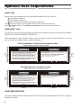
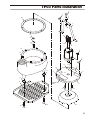
User’s Manual
TP03
HYDRAULIC
TRASH PUMP
MODEL: TP0300301, TP0300303
DANGER
SERIOUS INJURY OR DEATH COULD RESULT
FROM THE IMPROPER REPAIR OR SERVICE OF
THIS TOOL.
Copyright c 2001 The Stanley Works
OPS USA & CE Version
58555
7/2002 Ver. 2
REPAIRS AND/OR SERVICE TO THIS TOOL
MUST ONLY BE DONE BY AN AUTHORIZED AND
CERTIFIED DEALER.
Table of Contents
TP03
Hydraulic
Trash Pump
SERVICING THE
TP03 Hydraulic Trash Pump
This manual contains Safety,
Operation, and Troubleshooting
information. Stanley Hydraulic Tools
recommends that servicing of
hydraulic tools, other than routine
maintenance, must be performed
by an authorized and certified
dealer. Please read the DANGER
warning on the cover and the
Copyright c 2001 The Stanley Works
All rights reserved.
Under copyright law, this document may
not be copied in whole or in part without
the prior written consent of The Stanley
Works. This exception does not permit
copies to be made for others, whether or
not sold. Under the law, copying includes
translating into another language, format
or medium. This copyright notice must
appear on any permitted copies.
2
Certificate of Conformity
3
Specifications
3
General Safety Instructions
4
Tools Decals and Tags
5
Hydraulic Hose Requirements
6
HTMA Requirements
7
Operating Instructions
8
Troubleshooting
10
Parts Illustration
11
Parts List
12
Accessories
12
Warranty
13
SAFETY FIRST
It is the responsibility of the operator and
service technician to read rules and
instructions for safe and proper operation and
maintenance.
A cautious worker using common sense is the
greatest safety device.
Certificate of Conformity
I, the undersigned:
Mellits, Kirk E.
Surname and First Names
hereby certify that the construction plant or equipment specified hereunder:
1. Category: Trash Pump (Hydraulic)
2. Make:
Stanley
3. Type:
TP0300301, TP0300303
4. Type Serial Number of equipment:
5. Year of manufacture:
2001
ALL
has been manufactured in conformity with- EEC Type examination as shown:
Directive:
EN 809
Approved body:
Self
Date of expiration:
N/A
EN ISO 3744
Date:
2001
6. Special Provisions:
Done at:
None
Stanley Hydraulic Tools, Milwaukie, Oregon USA
Date: 2001
Position: Engineering Manager
Signature:
Specifications
Pressure Range________1500-2000 psi / 140 bar
Maximum Back Pressure________ 250 psi / 17 bar
Couplers_________________ HTMA Flush Face
Per NFPA T3.20.15/ISO 16028
Connect Size & Type___ 1/2 in. Male Pipe Adapter
Weight_______ 31lbs./14kg(Urethane Case)
Overall Length________________ 14 in./ 35.5 cm
Overall Width__________________ 16 in./ 41 cm
Overall Height _______________16.5 in. / 41.9 cm
Max. Fluid Temp._____________ 140° F / 60° C
Capacity_________________450 gpm / 1688 lpm
Flow Range______________7-9 gpm / 26-34 lpm
Maximum Flow________________9 gpm / 34 lpm
System Type_____________O.C, HTMA Type 2
Porting________________________1/2 in. NPTF
Liquid Outlet Size______________Urethane Case,
3 inch Female Pipe
HTMA Class II___________7-9 gpm @ 2000 psi
30Lpm at 138bar
BHTMA CATEGORY
EHTMA Category_____30 lpm @ 138 bar
Sound Pressure______________ <85 dBA @ 1m
Vibration Level________________________N/A
3
General Safety Instructions
Always observe safety symbols. They are included for your safety and the protection of the tool.
WARNING
DANGER
This safety symbol may appear on
the tool. It is used to alert the
operator of an action that could
place him/her or others in a life
threatening situation.
This safety symbol appears in these
instructions to identify an action
that could cause bodily injury to the
operator or other personnel.
CAUTION
This safety symbol appears in these
instructions to identify an action or
condition that could result in
damage to the tool or other
equipment.
This tool will provide safe and dependable service if operated in accordance with the instructions
given in this manual. Read and understand this manual and any stickers and tags attached to the
tool and hoses before operation. Failure to do so could result in personal injury or equipment
damage.
A
Operator must start in a work area without bystanders. The operator must be familiar with all prohibited
work areas such as excessive slopes and dangerous terrain conditions.
A
Establish a training program for all operators to ensure safe operations.
A
Do not operate the tool unless thoroughly trained or under the supervision of an instructor.
A
Always wear safety equipment such as goggles, head protection, and safety shoes at all times when
operating the tool.
A
Do not inspect or clean the tool while the hydraulic power source is connected. Accidental engagement of
the tool can cause serious injury.
A
Do not operate this tool without first reading the Operating Instructions.
A
Do not install or remove this tool while the hydraulic power source is connected. Accidental engagement
of the tool can cause serious injury.
A
Never operate the tool if you cannot be sure that underground utilities are not present. Underground
electrical utilities present an electrocution hazard. Underground gas utilities present an explosion hazard.
Other underground utilities may present other hazards.
A
Do not wear loose fitting clothing when operating the tool. Loose fitting clothing can get entangled with
the tool and cause serious injury.
A
Supply hoses must have a minimum working pressure rating of 2500 psi/175 bar.
A
Be sure all hose connections are tight.
A
The hydraulic circuit control valve must be in the “OFF” position when coupling or uncoupling the tool.
Wipe all couplers clean before connecting. Failure to do so may result in damage to the quick couplers
and cause overheating. Use only lint-free cloths.
A
Do not operate the tool at oil temperatures above 140° F/60° C. Operation at higher oil temperatures can
cause operator discomfort and may cause damage to the tool.
A
Do not operate a damaged, improperly adjusted, or incompletely assembled tool.
A
To avoid personal injury or equipment damage, all tool repair, maintenance and service must only be
performed by authorized and properly trained personnel.
A
Do not exceed the rated limits of the tool or use the tool for applications beyond its design capacity.
A
Always keep critical tool markings, such as labels and warning stickers legible.
A
Always replace parts with replacement parts recommended by Stanley Hydraulic Tools.
A
Check fastener tightness often and before each use daily.
4
Tool Decals & Tags
A Name Tag Sticker is attached to the tool. Never exceed the flow and pressure levels specified on
this sticker. The information listed on the name tag sticker must be legible at all times. Replace this
sticker if it becomes worn or damaged. A replacement is available from your local Stanley
distributor.
28786
Coupler
Sticker
30Lpm at 138bar
BHTMA CATEGORY
11207
Circuit Type “D” Decal
28788
Manual Sticker
Stanley Sticker
05152
CAUTION
7-9 GPM/ 26-34 LPM
DO NOT EXCEED 2000 PSI/ 140 BAR
n DO NOT EXCEED SPECIFIED FLOW OR PRESSURE. n USE
CLOSED-CENTER TOOL ON CLOSED-CENTER SYSTEM. n USE
OPEN-CENTER TOOL ON OPEN-CENTER SYSTEM. n CORRECTLY
CONNECT HOSES TO TOOL "IN" AND "OUT" PORTS. n IMPROPER
HANDLING, USE OR MAINTENANCE OF TOOL COULD RESULT IN
A LEAK, BURST OR OTHER TOOL FAILURE. n CONTACT AT A
LEAK OR BURST CAN CAUSE OIL INJECTION INTO THE BODY. n
FAILURE TO OBSERVE THESE PRECAUTIONS CAN RESULT IN
SERIOUS PERSONAL INJURY.
03796
Model and Serial
Number Information
03786
Caution
Sticker
28322
“CE” Decal
DANGER
DANGER
1. FAILURE TO USE HYDRAULIC HOSE LABELED AND
CERTI-FIED AS NON-CONDUCTIVE WHEN USING
HYDRAULIC TOOLS ON OR NEAR ELECTRICAL LINES
MAY RESULT IN DEATH OR SERIOUS INJURY.
BEFORE USING HOSE LABELED AND CERTIFIED AS
NON- CONDUCTIVE ON OR NEAR ELECTRIC LINES.
BE SURE THE HOSE IS MAINTAINED AS NON- CONDUC TIVE . THE
HOSE SHOULD BE REGULARLY TESTED FOR ELECTRIC CURRENT
LEAKAGE IN ACCORDANCE WITH YOUR SAFETY DEPARTMENT
INSTRUCTIONS.
2. A HYDRAULIC LEAK OR BURST MAY CAUSE OIL
INJECTION INTO THE BODY OR CAUSE OTHER SEVERE PERSONAL
INJURY.
A.DO NOT EXCEED SPECIFIED FLOW AND
PRESSURE FOR THIS TOOL. EXCESS FLOW OR
PRESSURE MAY CAUSE A LEAK OR BURST.
B. DO NOT EXCEED RATED WORKING PRESSURE
OF HYDRAULIC HOSE USED WITH THIS TOOL.
EXCESS PRESSURE MAY CAUSE A LEAK OR
BURST.
C. C H E C K T O O L , H O S E , C O U P L E R S &
C O N N E C T O R S
D A I L Y
F O R
LEAKS. DO NOT FEEL FOR LEAKS WITH
YOUR HANDS. CONTACT WITH A LEAK MAY
RESULT IN SEVERE PERSONAL INJURY.
The SAFETY TAG, P/N 15875, shown at right, smaller
than actual size, is attached to the tool when shipped
from the factory. Read and understand the safety
instructions listed on this tag before removal. We
suggest you retain this tag and attach it to the tool
when not in use.
D. DO NOT LIFT OR CARRY TOOL BY THE HOSES. DO NOT ABUSE
HOSE. DO NOT USE KINKED, TORN OR DAMAGED HOSES.
3. MAKE SURE HYDRAULIC HOSES ARE PROPERLY
CONN-ECTED TO THE TOOL BEFORE PRESSURIZING
SYSTEM. SYSTEM PRESSURE HOSE MUST ALWAYS
BE CONNECTED TO TOOL “IN” PORT. SYSTEM
RETURN HOSE MUST ALWAYS BE CONNECTED AT
TOOL “OUT” PORT. REVERSING CONNECTIONS MAY
CAUSE REVERSE TOOL OPERATION WHICH CAN
CAUSE SEVERE PERSONAL INJURY.
4. DO NOT CONNECT CLOSED-CENTER TOOLS TO
OPEN-CENTER HYDRAULIC SYSTEMS. THIS MAY
CAUSE EXTREME SYSTEM HEAT AND/OR SEVERE
PERSONAL INJURY.
DO NOT CONNECT OPEN-CENTER TOOLS TO CLO SE D- CE NT ER
HYDRAULIC SYSTEMS. THIS MAY RESULT IN LOSS OF OTHER
HYDRAULIC FUNCTIONS POWERED BY THE SAME SYSTEM AND/OR
SEVERE PERSONAL INJURY.
5. BYSTANDERS MAY BE INJURED IN YOUR WORK
AREA. KEEP BYSTANDERS CLEAR OF YOUR WORK
AREA.
6. WEAR HEARING, EYE, FOOT, HAND AND HEAD PROTECTION.
7. TO AVOID PERSONAL INJURY OR EQUIPMENT DAMAGE, ALL TOOL
REPAIR, MAINTENANCE AND
SERVICE MUST BE
PERFORMED BY AUTHORIZED
AN D PR OP ER LY
TRAINED PERSONNEL.
IMPORTANT
IMPORTANT
READ OPERATION MANUAL AND
SAFETY INSTRUCTIONS FOR THIS
TOOL BEFORE USING IT.
READ OPERATION MANUAL AND
SAFETY INSTRUCTIONS FOR THIS
TOOL BEFORE USING IT.
USE ONLY PARTS AND REPAIR
PROCEDURES APPROVED BY
STANLEY AND DESCRIBED IN THE
OPERATION MANUAL.
USE ONLY PARTS AND REPAIR
PROCEDURES APPROVED BY
STANLEY AND DESCRIBED IN THE
OPERATION MANUAL.
TAG TO BE REMOVED ONLY BY TOOL
OPERATOR.
(517)
SEE OTHER SIDE
15875
TAG TO BE REMOVED ONLY BY TOOL
OPERATOR.
(517)
SEE OTHER SIDE
15875
5
Hydraulic Hose Requirements
HOSE TYPES
Hydraulic hose types authorized for use with Stanley Hydraulic Tools are as follows:
Certified non-conductive
Wire-braided (conductive)
Fabric-braided (not certified or labeled non-conductive)
Hose listed above is the only hose authorized for use near electrical conductors.
Hoses and listed above are conductive and must never be near electrical conductors.
HOSE SAFETY TAGS
To help ensure your safety, the following DANGER tags are attached to all hoses purchased from Stanley
Hydraulic Tools. DO NOT REMOVE THESE TAGS.
If the information in a tag is illegible because of wear or damage, replace the tag immediately. A new tag
may be obtained at no charge from your Stanley Distributor.
This Tag attached to “Certified Non-Conductive” hose.
DANGER
1. FAILURE TO USE HYDRAULIC HOSE LABELED AND CERTIFIED AS NON-CONDUCTIVE WHEN USING
HYDRAULIC TOOLS ON OR NEAR ELECTRIC LINES MAY RESULT IN DEATH OR SERIOUS INJURY.
FOR PROPER AND SAFE OPERATION, MAKE SURE THAT YOU HAVE BEEN PROPERLY TRAINED IN
CORRECT PROCEDURES REQUIRED FOR WORK ON OR AROUND ELECTRIC LINES.
2. BEFORE USING HYDRAULIC HOSE LABELED AND CERTIFIED AS NON-CONDUCTIVE ON OR NEAR
ELECTRIC LINES, WIPE THE ENTIRE LENGTH OF THE HOSE AND FITTINGS WITH A CLEAN,
DRY, ABSORBENT CLOTH TO REMOVE DIRT AND MOISTURE AND TEST HOSE FOR MAXIMUM
ALLOWABLE CURRENT LEAKAGE IN ACCORDANCE WITH SAFETY DEPARTMENT INSTRUCTIONS.
DANGER
4. HANDLE AND ROUTE HOSE CAREFULLY TO AVOID KINKING, ABRASION, CUTTING OR CONTACT
WITH HIGH TEMPERATURE SURFACES. DO NOT USE IF KINKED. DO NOT USE HOSE TO PULL OR
LIFT TOOLS, POWER UNITS, ETC.
5. CHECK ENTIRE HOSE FOR CUTS, CRACKS, LEAKS, ABRASIONS, BULGES OR DAMAGE TO
COUPLINGS. IF ANY OF THESE CONDITIONS EXIST, REPLACE THE HOSE IMMEDIATELY.
NEVER USE TAPE OR ANY DEVICE TO ATTEMPT TO MEND THE HOSE.
6.
AFTER EACH USE, STORE IN A CLEAN, DRY AREA.
3. DO NOT EXCEED HOSE WORKING PRESSURE OR ABUSE HOSE. IMPROPER USE OR HANDLING OF
HOSE COULD RESULT IN BURST OR OTHER HOSE FAILURE. KEEP HOSE AS FAR AWAY AS
POSSIBLE FROM BODY AND DO NOT PERMIT DIRECT CONTACT DURING USE. CONTACT AT THE
BURST CAN CAUSE BODILY INJECTION AND SEVERE PERSONAL INJURY.
SEE OTHER SIDE
SEE OTHER SIDE
Side 1
Side 2
DO NOT REMOVE THIS TAG
DO NOT REMOVE THIS TAG
(shown smaller than actual size) p/n 27987
This Tag attached to “Conductive” hose.
DANGER
DANGER
1. DO NOT USE THIS HYDRAULIC HOSE ON OR NEAR ELECTRIC LINES. THIS HOSE IS NOT
LABELED OR CERTIFIED AS NON-CONDUCTIVE. USING THIS HOSE ON OR NEAR ELECTRIC LINES
MAY RESULT IN DEATH OR SERIOUS INJURY.
5. CHECK ENTIRE HOSE FOR CUTS, CRACKS, LEAKS, ABRASIONS, BULGES OR DAMAGE TO
COUPLINGS. IF ANY OF THESE CONDITIONS EXIST, REPLACE THE HOSE IMMEDIATELY.
NEVER USE TAPE OR ANY DEVICE TO ATTEMPT TO MEND THE HOSE.
2. FOR PROPER AND SAFE OPERATION, MAKE SURE THAT YOU HAVE BEEN PROPERLY TRAINED IN
CORRECT PROCEDURES REQUIRED FOR WORK ON OR AROUND ELECTRIC LINES.
6.
AFTER EACH USE, STORE IN A CLEAN, DRY AREA.
3. DO NOT EXCEED HOSE WORKING PRESSURE OR ABUSE HOSE. IMPROPER USE OR HANDLING OF
HOSE COULD RESULT IN BURST OR OTHER HOSE FAILURE. KEEP HOSE AS FAR AWAY AS
POSSIBLE FROM BODY AND DO NOT PERMIT CONTACT DURING USE. CONTACT AT THE
BURST CAN CAUSE BODILY INJECTION AND SEVERE PERSONAL INJURY.
4. HANDLE AND ROUTE HOSE CAREFULLY TO AVOID KINKING, ABRASION, CUTTING OR CONTACT
WITH HIGH TEMPERATURE SURFACES. DO NOT USE IF KINKED. DO NOT USE HOSE TO PULL OR
LIFT TOOLS, POWER UNITS, ETC.
SEE OTHER SIDE
SEE OTHER SIDE
Side 1
Side 2
DO NOT REMOVE THIS TAG
DO NOT REMOVE THIS TAG
(shown smaller than actual size) p/n 29144
HOSE PRESSURE RATING
The rated working pressure of the hydraulic hose must be equal to or higher than the relief valve setting on
the hydraulic system.
6
HTMA Requirements
NOTE: These are general hydraulic system requirements. See tool specification
page for tool specific requirements.
Hydraulic System
Requirements
Tool
Category:
C
20Lpm at 138bar
BHTMA CATEGORY
Type I
30Lpm at 138bar
BHTMA CATEGORY
Type II
Type III
4-6 GPM (15-23 lpm)
2000 psi (138 bar)
7-9 GPM (26-34 lpm)
2000 psi (138 bar)
11-13 GPM (42-49 lpm)
2000 psi (138 bar)
2100-2250
2100-2250
2100-2250
(145-155 bar)
(145-155 bar)
(145-155 bar)
250 psi
250 psi
250 psi
(17 bar)
(17 bar)
(17 bar)
(at min. operating temperature)
400 SSU
400 SSU
400 SSU
(82 centistokes)
(82 centistokes)
(82 centistokes)
Temperature
Sufficient heat rejection capacity
to limit max. fluid temperature to:
140° F (60° C)
140° F (60° C)
140° F (60° C)
3 hp (2.24 kW)
40° F (22° C)
5 hp (3.73 kW)
40° F (22° C)
7 hp (5.22 kW)
40° F (22° C)
Flow rate
Tool Operating Pressure
(at the power supply outlet)
System relief valve setting
(at the power supply outlet)
Maximum back pressure
(at tool end of the return hose)
Measured at a max. fluid viscosity of:
(at max. expected ambient temperature)
Min. cooling capacity
at a temperature difference of
between ambient and fluid temps
NOTE: Do not operate the tool at oil temperatures above 140° F (60° C). Operation at higher temperatures can cause operator
discomfort at the tool.
Filter
Min. full-flow filtration
sized for flow of at least:
25 microns
30 GPM (114 lpm)
25 microns
30 GPM (114 lpm)
25 microns
30 GPM (114 lpm)
(For cold temp. startup and max. dirt-holding capacity)
Hydraulic fluid
Petroleum based
(premium grade, anti-wear, non-conductive)
Viscosity
(at min. and max. operating temps)
100-400 SSU*
100-400 SSU*
100-400 SSU*
(20-82 centistokes)
(20-82 centistokes)
(20-82 centistokes)
NOTE: When choosing hydraulic fluid, the expected oil temperature extremes that will be experienced in service determine the
most suitable temperature viscosity characteristics. Hydraulic fluids with a viscosity index over 140 will meet the requirements over
a wide range of operating temperatures.
*SSU = Saybolt Seconds Universal
NOTE: These are general hydraulic system requirements. See tool Specification page for
tool specific requirements.
7
Operating Instructions
Pre-operation Procedures
Pump Operation
Check The Power Source
1. Observe all safety precautions.
1. Using the calibrated flowmeter and pressure
gauge, check that the hydraulic power source
develops a flow of 7-9 gpm/26-34 lpm at
1500-2000 ps/105-140 bar.
2. Attach a 3-inch/76 mm diameter discharge
hose to the pump outlet. For the best
performance, keep the discharge hose as short
as possible and lay it out to avoid sharp bends
or kinks.
2. Make certain the hydraulic power source is
equipped with a relief valve set to crack at
2150-2250 psi/150-155 bar maximum.
3. Check that the pump inlet is clear of debris.
Remove any obstructions before operating
the pump. Refer to CLEANING THE
PUMPING CHAMBER.
Connect Hoses
1. Wipe all hose couplers with a clean lint-free
cloth before making connections.
Do not attach a nozzle to the outlet of the
discharge hose. For high-pressure water pumping,
use a Stanley SM20 and nozzle. The TP03 is
designed for high gpm water flow at low pressure.
3. Attach a rope or cable to the lifting eye at the
top of the pump. Lower the pump into the
liquid to be pumped. Do not raise or lower the
pump by its hoses or couplers to avoid
damage to the hoses or couplers.
WARNING
Never point the hose at bystanders.
CAUTION
Do not connect pressure to the return port. Motor
shaft seal limit is 250 psi/17 bar.
2. Connect the hoses from the hydraulic power
source to the couplers on the pump or pump
hoses. It is a good practice to connect return
hoses first and disconnect them last to
minimize or avoid trapped pressure in the
pump motor.
NOTE: If uncoupled hoses are left in the
sun, heat may cause a pressure increase
inside the hoses making them difficult to
connect. When possible, connect the free
ends of the operating hoses together.
3. If hose couplers are used, observe the arrow
on the coupler to ensure that the flow is in
the proper direction. The female coupler on
the pump is the inlet coupler.
8
4. Turn on the hydraulic power source.
NOTE: It will not damage the pump to run
it “DRY”
5. When pumping is completed, set the hydraulic
on/off valve at the hydraulic power source to
OFF. Lift the pump from the liquid using
the rope or cable.
CAUTION
Perform steps 6 thru 8 for pump protection and care.
6. The pump must maintain a minimum RPM
and water speed to move solid particles
through the pump (high speed water is
required to push solids through the large
pump). When pumping liquids containing
large solids, monitor the flow from the outlet
of the discharge hose. If it begins to slow turn
off the hydraulic power source and raise the
pump. Disconnect the hydraulic hoses. See
CLEANING THE PUMPING CHAMBER.
Operating Instructions
CAUTION
Pumping liquids with a solids-to-liquid ratio greater than
30% solids to 70% liquid will accelerate impeller wear.
7. To maintain performance it is good practice to
periodically inspect the impeller for wear or
damage. This is especially important
following the pumping of liquids containing
sharp, abrasive solids.
8. Turn off the hydraulic power source before
raising the pump. Raise the pump by the rope
or cable attached to its top to avoid damaging
the hoses and couplings.
Cold Weather Operation
If the pump is to be used during cold weather,
preheat the hydraulic fluid at low engine speed.
When using the normally recommended fluids,
fluid should be at or above 50°F/10°C (400 ssu/
82 centistrokes) before use.
Damage to the hydraulic system or pump motor
could result from using fluid that is too viscous or
thick.
Cleaning The Pumping Chamber
2. Clear the debris and determine whether or not
the discharge hose is clogged or the power
source is not providing adequate flow/pressure
to properly drive the pump. If the pump is not
cleared, heavy solids will not be removed
from the pump, eventually damaging or
destroying the impeller.
3. Place the motor adapter plate over the case
studs.
4. Install the handle and lifting eye on the motor
adapter plate and secure with six 3/8-16 wing
nuts. Tighten by hand only.
5. Install the hoses and couplers.
NOTE: A slot has been milled in the
underside of the aluminum motor adapter
plate near the pump outlet. This slot
allows air near the impeller to be
submerged and prevents binding.
Inspect this slot before each use to ensure
that no obstruction blocks this vent slot.
It is normal for a small amount of water to squirt
from this slot while pumping.
1. Remove the six 3/8-16 wing nuts securing the
motor adapter plate and motor to the case.
9
Troubleshooting
This section describes how to find and resolve problems users may experience. If a situation occurs that is
not covered, call your Stanley Customer Service representative for assistance.
WARNING
Inspecting the tool or installing parts with the hydraulic hoses connected can result in severe personal injury or equipment
damage.
To prevent accidental startup, disconnect the hydraulic power before beginning any inspection or installation task.
If symptoms of poor performance develop, the following chart can be used as a guide to correct the problem.
When diagnosing faults in operation of the tool, always check that the hydraulic power source is supplying
the correct hydraulic flow and pressure to the tool as listed in the table. Use a flowmeter known to be
accurate. Check the flow with the hydraulic oil temperature at least 80° F/27° C.
Symptom
Tool will not start.
Possible Cause
No hydraulic flow or pressure.
Turn on power source and check
that 7-9 gpm / 26-34 lpm at
1500-2000 psi / 101-140 bar is
available at the pump.
Defective couplers.
Check the couplers by connecting
them together with the hydraulic
power source operating and the
control valve “ON”. The power
supply should operate without
“loading” from plugged couplers.
Impeller jammed with debris.
Clean the pumping chamber as
described in the OPERATING
INSTRUCTIONS section of this
manual.
Contact Authorized Distributor.
Motor failure.
Poor tool
performance.
Hydraulic oil in
discharge flow.
10
Solution
Incorrect hydraulic flow or pressure. Turn “ON” power source, check that
7-9 gpm/ 26-34 lpm at
1500-2000 psi/ 101-149 bar is
available at the pump.
Inlet to pump may be blocked.
Inspect and clear. If pump settled
into sediment, suspend pump
above sediment or place flat, solid
surface under the pump.
Discharge hose restricted.
Straighten hose and remove kinks.
Impeller worn excessively.
Contact Authorized Distributor.
Motor shaft seal failure.
Contact Authorized Distributor.
TP03 Parts Illustration
2
1
3
29
4
3
28
20
27
5
26
19
6
25
8
7
24
1
16
18
17
9
15
21
10
14
21
23
MODEL/SN
INFO
11
12
22
22
12
13
11
TP03 Parts List
NOTE: Earlier models of the TP03 used a “DOWTY or HEMA” motor. If you are
currently using a earlier TP03 with either of these motors installed, see your
Authorized Distributor to obtain a correct manual (Manual P/N-07218).
NOTE:
Use Part Number and
Description when ordering.
Item
1
2
3
4
5
6
7
8
9
10
11
12
13
14
15
16
17
18
19
20
21
22
23
24
25
26
27
28
29
Part
No .
Description
QTY
07210
07208
371503
07207
24061
06264
24381
04353
03786
28322
07202
21978
07200
05152
28786
11207
28788
00635
39426
24060
38702
38701
07206
07209
21917
51301
09661
01324
22294
07201
Wing Nut, 3/ 8-16- TP03
Eye Bolt, 3/8-16- TP03
Nut 3/8-16 UNC PLT
Handle- TP03
Male Coupler
Adaptor Fit. -12/1/2 NPT
TP03 Motor Cassapa
Nut, 3/8-16 ESNA
GPM Sticker
Sticker “CE” 25 mm
Motor Adapter Plate
Capscrew 3/8-16 x 1.75
Impeller-TP03
Stanley Sticker
Coupler Sticker
Circuit Type D Sticker
Manual Sticker
Key, Motor Shaft, 3/16 x 3/4
Adaptor -14 SAE / 1/2NPT
Female Coupler
Jam Nut, 1/ 2-13 Zinc
Screw, Slot FHMS
Pump Support- TP03
Stud, 3/8-16 x 2- TP03
Urethane Bowl
TP0300303 (Venezuelan Army Only)
Capscrew- TP04
Lockwasher
Washer
Rubber Gasket- Tp03
6
1
2
1
1
1
1
2
1
1
1
2
1
1
1
1
1
1
1
1
3
3
1
6
1
1
1
1
1
26230
Seal Kit
1
Accessories
NOTE:
Use Part Number and
Description when ordering.
12
Part
Description
56761
3 inch x 25 ft Lay-Flat Cam-Lock Hose
52720
3 inch Male Pipe x 3 in Male Cam-Lock Fitting
Warranty
Stanley Hydraulic Tools (hereinafter called “Stanley”), subject to the exceptions contained below, warrants new hydraulic tools for a period of one
year from the date of sale to the first retail purchaser, or for a period of 2 years from the shipping date from Stanley, whichever period expires first,
to be free of defects in material and/or workmanship at the time of delivery, and will, at its option, repair or replace any tool or part of a tool, or new
part, which is found upon examination by a Stanley authorized service outlet or by Stanley’s factory in Milwaukie, Oregon to be DEFECTIVE IN
MATERIAL AND/OR WORKMANSHIP.
EXCEPTIONS FROM WARRANTY
NEW PARTS: New parts which are obtained individually are warranted, subject to the exceptions herein, to be free of defects in material and/or
workmanship at the time of delivery and for a period of 6 months after the date of first usage. Seals and diaphragms are warranted to be free of
defects in material and/or workmanship at the time of delivery and for a period of 6 months after the date of first usage or 2 years after the date of
delivery, whichever period expires first. Warranty for new parts is limited to replacement of defective parts only. Labor is not covered.
FREIGHT COSTS: Freight costs to return parts to Stanley, if requested by Stanley for the purpose of evaluating a warranty claim for warranty
credit, are covered under this policy if the claimed part or parts are approved for warranty credit. Freight costs for any part or parts which are not
approved for warranty credit will be the responsibility of the individual.
SEALS & DIAPHRAGMS: Seals and diaphragms installed in new tools are warranted to be free of defects in material and/or workmanship for a
period of 6 months after the date of first usage, or for a period of 2 years from the shipping date from Stanley, whichever period expires first.
CUTTING ACCESSORIES: Cutting accessories such as breaker tool bits are warranted to be free of defects in material and or workmanship at
the time of delivery only.
ITEMS PRODUCED BY OTHER MANUFACTURERS: Components which are not manufactured by Stanley and are warranted by their respective
manufacturers.
a. Costs incurred to remove a Stanley manufactured component in order to service an item manufactured by other
manufacturers.
ALTERATIONS & MODIFICATIONS: Alterations or modifications to any tool or part. All obligations under this warranty shall be terminated if the
new tool or part is altered or modified in any way.
NORMAL WEAR: Any failure or performance deficiency attributable to normal wear and tear such as tool bushings, retaining pins, wear plates,
bumpers, retaining rings and plugs, rubber bushings, recoil springs, etc.
INCIDENTAL/CONSEQUENTIAL DAMAGES: To the fullest extent permitted by applicable law, in no event will STANLEY be liable for any
incidental, consequential or special damages and/or expenses.
FREIGHT DAMAGE: Damage caused by improper storage or freight handling.
LOSS TIME: Loss of operating time to the user while the tool(s) is out of service.
IMPROPER OPERATION: Any failure or performance deficiency attributable to a failure to follow the guidelines and/or procedures as outlined in
the tool’s operation and maintenance manual.
MAINTENANCE: Any failure or performance deficiency attributable to not maintaining the tool(s) in good operating condition as outlined in the
Operation and Maintenance Manual.
HYDRAULIC PRESSURE & FLOW, HEAT, TYPE OF FLUID: Any failure or performance deficiency attributable to excess hydraulic pressure,
excess hydraulic back-pressure, excess hydraulic flow, excessive heat, or incorrect hydraulic fluid.
REPAIRS OR ALTERATIONS: Any failure or performance deficiency attributable to repairs by anyone which in Stanley’s sole judgement caused
or contributed to the failure or deficiency.
MIS-APPLICATION: Any failure or performance deficiency attributable to mis-application. “Mis-application” is defined as usage of products for
which they were not originally intended or usage of products in such a matter which exposes them to abuse or accident, without first obtaining the
written consent of Stanley. PERMISSION TO APPLY ANY PRODUCT FOR WHICH IT WAS NOT ORIGINALLY INTENDED CAN ONLY BE OBTAINED
FROM STANLEY ENGINEERING.
WARRANTY REGISTRATION: STANLEY ASSUMES NO LIABILITY FOR WARRANTY CLAIMS SUBMITTED FOR WHICH NO TOOL REGISTRATION IS ON RECORD. In the event a warranty claim is submitted and no tool registration is on record, no warranty credit will be issued without first
receiving documentation which proves the sale of the tool or the tools’ first date of usage. The term “DOCUMENTATION” as used in this
paragraph is defined as a bill of sale, or letter of intent from the first retail customer. A WARRANTY REGISTRATION FORM THAT IS NOT ALSO ON
RECORD WITH STANLEY WILL NOT BE ACCEPTED AS “DOCUMENTATION”.
NO ADDITIONAL WARRANTIES OR REPRESENTATIONS
This limited warranty and the obligation of Stanley thereunder is in lieu of all other warranties, expressed or implied including merchantability or
13
For additional Sales & Service information, contact:
Stanley Hydraulic Tools
Division of the Stanley Works
3810 SE Naef Road
Milwaukie, OR 97267 USA
Tel: (503) 659-5660
Fax: (503) 652-1780