1
$#
" "! "
! $ Important User Information
Because of the variety of uses for the products described in this
publication, those responsible for the application and use of this control
equipment must satisfy themselves that all necessary steps have been
taken to assure that each application and use meets all performance and
safety requirements, including any applicable laws, regulations, codes
and standards.
The illustrations, charts, sample programs and layout examples shown in
this guide are intended solely for example. Since there are many
variables and requirements associated with any particular installation,
Allen-Bradley does not assume responsibility or liability (to include
intellectual property liability) for actual use based upon the examples
shown in this publication.
Allen-Bradley publication SGI–1.1, “Safety Guidelines For The
Application, Installation and Maintenance of Solid State Control”
(available from your local Allen-Bradley office) describes some
important differences between solid-state equipment and
electromechanical devices which should be taken into consideration
when applying products such as those described in this publication.
Reproduction of the contents of this copyrighted publication, in whole or
in part, without written permission of Allen–Bradley Company, Inc.
is prohibited.
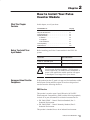
Throughout this manual we make notes to alert you to possible injury to
people or damage to equipment under specific circumstances.
!
ATTENTION: Identifies information about practices or
circumstances that can lead to personal injury or death,
property damage, or economic loss.
Attention helps you:
• identify a hazard
• avoid the hazard
• recognize the consequences
Important: Identifies information that is especially important for
successful application and understanding of the product.
Important: We recommend you frequently backup your application
programs on appropriate storage medium to avoid possible
data loss.
DeviceNet, DeviceNetManager, and RediSTATION are trademarks of Allen-Bradley Company, Inc.
PLC, PLC–2, PLC–3, and PLC–5 are registered trademarks of Allen-Bradley Company, Inc.
Windows is a trademark of Microsoft.
Microsoft is a registered trademark of Microsoft
IBM is a registered trademark of International Business Machines, Incorporated.
All other brand and product names are trademarks or registered trademarks of their respective companies.
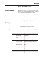
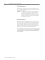
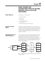
Purpose of this Manual
Audience
This manual shows you how to use your FLEX I/O pulse counter
module with Allen-Bradley programmable controllers. The manual
helps you install, program and troubleshoot your module.
You must be able to program and operate an Allen-Bradley
programmable controller to make efficient use of your FLEX I/O
module. In particular, you must know how to program block
transfers.
We assume that you know how to do this in this manual. If you do
not, refer to the appropriate programming and operations manual
before you attempt to program your modules.
Vocabulary
In this manual, we refer to:
– the pulse counter module as the “input module”
– the Programmable Controller as the “controller”
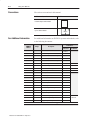
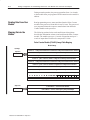
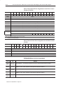
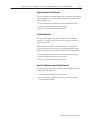
Manual Organization
This manual is divided into seven chapters. The following chart lists
each chapter with its corresponding title and a brief overview of the
topics covered in that chapter.
Chapter
Title
Contents
1
4%04)%5 .& !-$ 2(%
3+1% .3-2%0 .$3+%
%1#0)"%1 /3+1% #.3-2%0 ,.$3+%1 &%!230%1 !-$
(.5 2(%7 &3-#2).-
2
.5 2. -12!++ .30 3+1% .3-2%0
.$3+%
.5 2. )-12!++ !-$ 5)0% 2(% ,.$3+%
3
.$3+% 0.'0!,,)-'
6/+!)-1 "+.#* 20!-1&%0 /0.'0!,,)-' 1!,/+% /0.'0!,1
4
0)2)-' .-&)'30!2).- 2. !-$
%!$)-' 2!231 0., 5)2( !
%,.2% $!/2%0
6/+!)-1 (.5 2. #.-&)'30% 7.30 ,.$3+%1 !-$ 0%!$ 12!231
)-&.0,!2).- &0., 7.30 ,.$3+%1 5(%- 31)-' ! 0%,.2% !$!/2%0
5
.5 .,,3-)#!2).- !*%1 +!#%
!-$ ,!'% !"+% !//)-'
5)2( 2(% %4)#%%2 $!/2%0
6/+!)-1 (.5 7.3 #.,,3-)#!2% 5)2( 7.30 ,.$3+%1 !-$
(.5 2(% ),!'% )1 ,!//%$ 5(%- 31)-' ! %4)#%%2
!$!/2%0
6
!+)"0!2)-' .30 3+1% .3-2%0
.$3+%
.5 2. #!+)"0!2% 2(% ,.$3+%
7
0.3"+%1(..2 .30 3+1% .3-2%0
.$3+%
.5 2. 31% 2(% )-$)#!2.01 2. 20.3"+%1(..2 7.30 ,.$3+%
Appendix
Title
A
/%#)&)#!2).-1
Contents
/%#)&)#!2).-1 &.0 2(% /3+1% #.3-2%0 ,.$3+%
3"+)#!2).- 8
3'312 P–2
Using This Manual
Conventions
We use these conventions in this manual:
In this manual, we show:
Like this:
1' 1 1'$/$ (0 +-/$ (,%-/+ 1(-, !-21 1-.("
(, ,-1'$/ "' .1$/ (, 1'(0 + ,2 *
1' 1 1'$/$ (0 +-/$ (,%-/+ 1(-, !-21 1'$
1-.(" (, ,-1'$/ + ,2 *
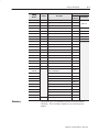
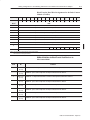
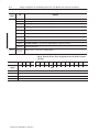
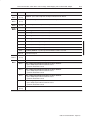
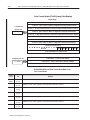
For Additional Information
Catalog
Number
More
For additional information on FLEX I/O systems and modules, refer
to the following documents:
Publications
Voltage
Description
Installation
Instructions
/-#2"1 1
5
User Manual
5
#"
-,1/-*$1 # .1$/
5
5
#"
$#2,# ,1 $#( -,1/-*$1 # .1$/
5
5
#"
-,1/-*$1 # .1$/
5
5
#"
$#2,# ,1 $#( -,1/-*$1 # .1$/
5
5
#"
$3("$$1 # .1$/
5
5
5
#"
$+-1$ # .1$/
5
5
5
#"
5*-1 $+-1$ # .1$/
5
5
5
#"
/-%(!20 # .1$/
5
5
5
#"
(,) ,.21 -#2*$
5
5
#"
-2/"$ 21.21 -#2*$
5
5
#"
(,) ,.21 -#2*$
5
5
#"
-2/"$ 21.21 -#2*$
5
5
#"
-2/"$ ,.21 -#2*$
5
5
#"
(,) 21.21 -#2*$
5
5
#"
*$"1/-,(" **4 20$# 21.21 -#2*$
5
5
#"
$,0-/ ,.21 -#2*$
5
5
#"
,.21 21.21 -#2*$
5
5
#"
$*$"1 !*$ , *-& ,.21 -#2*$
5
5
#"
$*$"1 !*$ , *-& 21.21 -#2*$
5
5
#"
,.21 21.21 , *-& -#2*$
5
Table continued on next page
2!*(" 1(-, 5 2&201 5
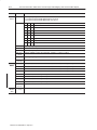
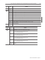
Using This Manual
Publications
Catalog
Number
Voltage
9
" '&
54054 3/,$4(' .$,/) /'5,(
9
9
" '&
.054 3/,$4(' .$,/) /'5,(
9
9#
" '&
.054 54054 3/,$4(' .$,/) /'5,(
9
9
" '&
.054 .$,/) /'5,(
9
9
9 " '&
*(2-/&/50,( .054 /'5,(
9
9
9 " '&
*(2-/&/50,( .054 /'5,(
9
9
9
" '&
2(15(.&8 .054 /'5,(
9
9
9
" '&
*$..(, 5,3( /5.4(2 /'5,(
9
9
9
" '&
" '& .054 /'5,(
9
9
" '&
" '& 54054 /'5,(
9
9
" $&
.054 /'5,(
9
9
" $&
54054 /'5,(
9
9
" $&
3/,$4(' .054 /'5,(
9
9
" $&
3/,$4(' 54054 /'5,(
9
9
" $&
.054 /'5,(
9
9
" $&
54054 /'5,(
9
9
" $&'&
.054 /'5,(
9
9
" $&'&
54054 /'5,(
9
9 9 96+2( (2-+.$, $3(
96+2( (2-+.$, $3(
9
9 (2-+.$, $3( !.+4
9
9 Description
Installation
Instructions
53(' (2-+.$, $3( !.+4
(-0(2$452( (2-+.$, $3( !.+4
9
9 02+.) ,$-0 (2-+.$, $3( !.+4
9
9 02+.) ,$-0 (-0(2$452( $3( !.+4
9
(2-+.$, $3( !.+4
9 9 9
9
9
" '&
User Manual
9
9
9 9 Summary
P–3
9
02+.) ,$-0 (2-+.$, $3( !.+4
9
74(.'(2 $%,(3
9
/5.4+.) +4
9
/6(2 500,8
9
This preface gave you information on how to use this manual
efficiently. The next chapter introduces you to the frequency
module.
5%,+&$4+/. 9! 5)534 P–4
Using This Manual
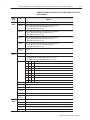
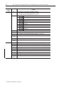
Table of Contents
Overview of the Pulse
Counter Module
Chapter 1
What This Chapter Contains . . . . . . . . . . . . . . . . . . . . . . . . . . . . .
How You Use the
Pulse Counter Module . . . . . . . . . . . . . . . . . . . . . . . . . . . . . .
What the Pulse Counter Module Does . . . . . . . . . . . . . . . . . . . . . .
Typical Applications . . . . . . . . . . . . . . . . . . . . . . . . . . . . . . . . . . .
Input Capabilities . . . . . . . . . . . . . . . . . . . . . . . . . . . . . . . . . . . . .
Variables . . . . . . . . . . . . . . . . . . . . . . . . . . . . . . . . . . . . . . . . .
Select Type of Measurement . . . . . . . . . . . . . . . . . . . . . . . .
Start Period Time Measurement . . . . . . . . . . . . . . . . . . . . . .
Check if the Measurement is Complete . . . . . . . . . . . . . . . . .
Select Clock Frequency . . . . . . . . . . . . . . . . . . . . . . . . . . . .
Select Number of Periods . . . . . . . . . . . . . . . . . . . . . . . . . . .
Chapter Summary . . . . . . . . . . . . . . . . . . . . . . . . . . . . . . . . . . . .
How to Install Your Pulse
Counter Module
Chapter 2
Programming Your Pulse
Counter Module
Chapter 3
1-1
1-1
1-3
1-4
1-4
1-4
1-4
1-5
1-5
1-5
1-6
1-6
What This Chapter Contains . . . . . . . . . . . . . . . . . . . . . . . . . . . . .
2-1
Before You Install Your Input Module . . . . . . . . . . . . . . . . . . . . . . .
2-1
European Union Directive Compliance . . . . . . . . . . . . . . . . . . . . . .
2-1
EMC Directive . . . . . . . . . . . . . . . . . . . . . . . . . . . . . . . . . . . . .
2-1
Low Voltage Directive . . . . . . . . . . . . . . . . . . . . . . . . . . . . . . . .
2-2
Power Requirements . . . . . . . . . . . . . . . . . . . . . . . . . . . . . . . . . .
2-2
Wiring the Terminal Base Units (1794ĆTB3G shown) . . . . . . . .
2-3
Installing the Module . . . . . . . . . . . . . . . . . . . . . . . . . . . . . . . . . .
2-4
Mounting the Terminal Base Unit on a DIN Rail . . . . . . . . . . . . .
2-4
Panel/Wall Mounting . . . . . . . . . . . . . . . . . . . . . . . . . . . . . . . .
2-6
Mounting the Pulse Counter Module on the Terminal Base Unit . .
2-7
Connecting Wiring for Your Pulse Counter Module . . . . . . . . . . . . .
2-9
Wiring to a 1794ĆTBN or ĆTBNF Terminal Base Unit . . . . . . . . . . 2-11
Wiring connections for the 1794-IP4 Pulse Counter Module . . . . 2-12
Example of 16-bit Period Time Measurement and 16-bit Accumulating
Pulse Counter Wiring (4 channels) . . . . . . . . . . . . . . . . . . . . 2-13
Example of 32-bit Period Time Measurement Wiring (4 channels) 2-13
Module Indicators . . . . . . . . . . . . . . . . . . . . . . . . . . . . . . . . . . . . 2-14
Chapter Summary . . . . . . . . . . . . . . . . . . . . . . . . . . . . . . . . . . . . 2-14
What This Chapter Contains . . . . . . . . . . . . . . . . . . . . . . . . . . . . .
Enter Block Transfer Instructions . . . . . . . . . . . . . . . . . . . . . . . . . .
PLCĆ2 Family Processor . . . . . . . . . . . . . . . . . . . . . . . . . . . . . .
PLCĆ5 Family Processor . . . . . . . . . . . . . . . . . . . . . . . . . . . . . .
SLCĆ5 Programming . . . . . . . . . . . . . . . . . . . . . . . . . . . . . . . . . .
Chapter Summary . . . . . . . . . . . . . . . . . . . . . . . . . . . . . . . . . . . .
3-1
3-1
3-2
3-2
3-3
3-8
Publication 1794ĆUM016B-EN-P - August 2002
ii
Table of Contents
Writing Configuration to and
Reading Status from Your
Module with a Remote I/O
Adapter
Chapter 4
How Communication Takes
Place and I/O Image Table
Mapping with the DeviceNet
Adapter
Chapter 5
Input, Output and
Configuration Files for
Analog Modules when used
with ControlNet
Publication 1794ĆUM016B-EN-P - August 2002
What This Chapter Contains . . . . . . . . . . . . . . . . . . . . . . . . . . . . .
4-1
Configuring Your Pulse Counter Module . . . . . . . . . . . . . . . . . . . . .
4-1
Reading Data From Your Module . . . . . . . . . . . . . . . . . . . . . . . . .
4-2
Mapping Data for the Module . . . . . . . . . . . . . . . . . . . . . . . . . . . .
4-2
Pulse Counter Module (1794ĆIP4) Image Table Mapping . . . . . . .
4-2
Block Transfer Read Word Assignments for the Pulse Counter Module
(1794ĆIP4) . . . . . . . . . . . . . . . . . . . . . . . . . . . . . . . . . . .
4-3
Bit/Word Definitions for Block Transfer Read Words for the
Pulse Counter Module . . . . . . . . . . . . . . . . . . . . . . . . . . .
4-3
Block Transfer Write Word Assignments for the Pulse
Counter Module . . . . . . . . . . . . . . . . . . . . . . . . . . . . . . .
4-4
Bit/Word Definitions for the Block Transfer Write Words for the Pulse
Counter Module . . . . . . . . . . . . . . . . . . . . . . . . . . . . . . .
4-4
Chapter Summary . . . . . . . . . . . . . . . . . . . . . . . . . . . . . . . . . . . .
4-5
What This Chapter Contains . . . . . . . . . . . . . . . . . . . . . . . . . . . . .
About DeviceNetManager Software . . . . . . . . . . . . . . . . . . . . . . . .
Polled I/O Structure . . . . . . . . . . . . . . . . . . . . . . . . . . . . . . . . . . .
Adapter Input Status Word . . . . . . . . . . . . . . . . . . . . . . . . . . . .
System Throughput . . . . . . . . . . . . . . . . . . . . . . . . . . . . . . . . . . .
Mapping Data into the Image Table . . . . . . . . . . . . . . . . . . . . . . . .
Pulse Counter Module (1794ĆIP4) Image Table Mapping . . . . . . .
Block Transfer Read Word Assignments for the Pulse Counter
Module (1794ĆIP4) . . . . . . . . . . . . . . . . . . . . . . . . . . . . .
Block Transfer Write Word Assignments for the Pulse
Counter Module . . . . . . . . . . . . . . . . . . . . . . . . . . . . . . .
Bit/Word Definitions for the Pulse Counter Module . . . . . . . . .
Defaults . . . . . . . . . . . . . . . . . . . . . . . . . . . . . . . . . . . . . . . . . . .
5-1
5-1
5-1
5-2
5-3
5-3
5-3
5-4
5-4
5-4
5-7
Chapter 6
Chapter Objectives . . . . . . . . . . . . . . . . . . . . . . . . . . . . . . . . . . .
About the ControlNet Adapter . . . . . . . . . . . . . . . . . . . . . . . . . . . .
Communication Over the FLEX I/O Backplane . . . . . . . . . . . . . . . .
Scheduled DataĆTransfer . . . . . . . . . . . . . . . . . . . . . . . . . . . . .
Unscheduled DataĆTransfer . . . . . . . . . . . . . . . . . . . . . . . . . . .
Module I/O Mapping . . . . . . . . . . . . . . . . . . . . . . . . . . . . . . . . .
I/O Structure . . . . . . . . . . . . . . . . . . . . . . . . . . . . . . . . . . . . . . . .
Adapter Input Status Word . . . . . . . . . . . . . . . . . . . . . . . . . . . .
Safe State Data . . . . . . . . . . . . . . . . . . . . . . . . . . . . . . . . . . . . . .
Device Actions . . . . . . . . . . . . . . . . . . . . . . . . . . . . . . . . . . . . . .
Communication Fault Behavior . . . . . . . . . . . . . . . . . . . . . . . . .
Idle State Behavior . . . . . . . . . . . . . . . . . . . . . . . . . . . . . . . . .
Input Data Behavior upon Module Removal . . . . . . . . . . . . . . . .
6-1
6-1
6-1
6-2
6-2
6-2
6-3
6-3
6-4
6-4
6-5
6-5
6-5
iii
Table of Contents
/'-! */).!, * /'! 1 (#! '! ++%)# %.*, !"%)%.%*)- "*, '*& ,)-"!, ! *, - "*, .$!
/'-! */).!, * /'! Troubleshoot the Pulse
Counter Module
Chapter 7
Specifications
Chapter 8
$. $%- $+.!, *).%)- ../- ) %.*,- $.- !0. +!%"%.%*)- /'%.%*) 1 /#/-. Table of Contents
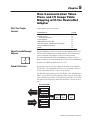
What This Chapter
Contains
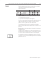
How You Use the
Pulse Counter Module
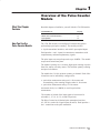
Read this chapter to familiarize yourself with the 1794–IP4 module.
For information on
See page
#) #( & ' (!& #("'% #(! ' ' (!& #("'% #(! #& "$(' $ ! ' & The 1794–IP4 module is an intelligent I/O module designed to
perform high speed pulse counting. The module provides:
• 4 pulse transmitter interfaces, each with 2 optocoupled inputs
Each input has + and – inputs for connection to transmitters with
complementary and noncomplementary signals.
The pulse inputs can accept frequencies up to 100KHz. The module
accepts and returns binary data.
The module’s primary use is accurate, high-speed counting of pulses
from flow meters or density meters. This includes quantity counting
and speed calculations.
The module has 2 16–bit up/down counters per channel. Each of the
4 interfaces can be individually configured for:
• period time measurement using one 16–bit counter and
accumulating pulse counting using the other 16–bit counter.
• period time measurement using a 32–bit counter.
An internal clock (1 or 10MHz) is used for period time
measurement.
The number of periods of the input signal to be measured is
selectable (1, 2, 4, 8, 16, 32, 64 and 128 periods).
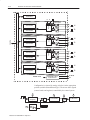
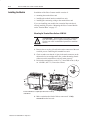
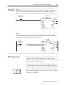
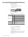
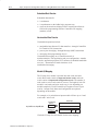
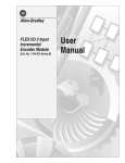
The Pulse Counter has 4 identical pulse transmitter interfaces
(12–24V dc), each with 2 signal inputs (N and D). Each input has +
and – connections to the pulse transmitter.
(! ' #" * ((&'
1–2
Overview of the Pulse Counter Module
(',*(& (*
),((-)&!*+
$, (-',!*
$, (-',!*
$, (-',!*
$, (-',!*
+
(#$
$, (-',!*
+
(#$
$, (-',!*
(#$
-+',!*"!
!*$&-+
(#$
$, (-',!*
$, (-',!*
12-24V dc
0V
.'$&&/ +(&,!
('.!*,!*
Internal +5V dc
Configuration is selected by setting A (below) in the appropriate
position (variable SelectMeasureType). The arrows show signals
(control words and registers) controlled by the control system.
,! (',*(&
)!*$( +
&(%
0
0
-&$,$(' 1 -#-+, &
$, (-',!*
$, (-',!*
A
Overview of the Pulse Counter Module
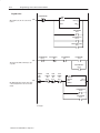
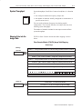
What the Pulse Counter
Module Does
1–3
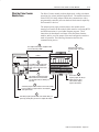
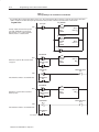
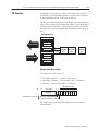
The Pulse Counter module performs high-speed scaling calculation
operations for various industrial applications. The module interfaces
with a FLEX I/O family adapter which then communicates with a
programmable controller processor that has block-transfer capability
and external I/O devices.
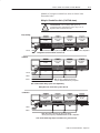
The adapter/power supply transfers data to the module (block
transfer write) and from the module (block transfer read) using BTW
and BTR instructions in your ladder diagram program. These
instructions let the adapter read input values and status from the
module, and let you write output values and configure the module’s
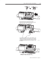
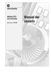
mode of operation. The following illustration describes the
communication process.
1
2
The adapter transfers your configuration data
to the module using a BTW.
External devices transmit
frequency signals to the modĆ
ule.
Flexbus
ADAPTER
LOCAL
ACTIVE
FAULT FAULT
4 CH Pulse Counter Module
24VDC
POWER SUPPLY
RIO ADAPTER
1794ĆASB
4
1794-IP4
1
OK
Your ladder program instructs the
adapter to perform a BTR of the
values and stores them in a data
table.
5
The adapter and module determine
that the transfer was made without
error and input values are within speciĆ
fied range.
6
3
The module converts
frequency signals into integer
format and stores these
values until the adapter
requests their transfer.
Your ladder program can use and/or move the data (if valid)
before it is written over by the transfer of new data in a
subsequent transfer.
7
Your ladder program performs BTWs to the module when you
power it up, and any time you wish to reconfigure the module.
Publication 1794ĆUM016B-EN-P - August 2002
1–4
Overview of the Pulse Counter Module
Typical Applications
You can use the 1794–IP4 module in the power management,
automotive, food and beverage, and oil and gas industries for various
flow and/or turbine metering applications. Some sample
applications include:
•
•
•
•
Input Capabilities
quantity counting
speed calulations
brewery flow monitoring
petrochemical flow and custody transfer
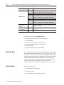
The Pulse Counter module has 4 identical input interfaces. Each of
the input channels may accept + and – input signals:
• N+ and N–
• D+ and D–
The pulse inputs can accept frequencies up to 100KHz. The module
accepts and returns binary data.
Each of the 4 counters has two 16–bit counter registers.
Variables
Communication between the Pulse Counter module and the control
system take place using variables accessible in the control system
program. Examples of variables are:
• selection of clock frequency (ClockFrequency)
• selection of measurement type (SelectMeasureType).
Control words are used to set parameters for configuration. Control
words sent to the Pulse Counter module are read back to the control
system to verify that at least 1 I/O scan has been performed since the
control system cycle which initiated the frequency module
command.
Select Type of Measurement
The module can be configured for 2 alternate functions using the
variable SelectMeasureType. Each of the 4 inputs can be individually
configured.
"! # "" ! Function
! "! " ! "! ! !
"! ! ""! "!
! "! " ! "! !
Overview of the Pulse Counter Module
1–5
Start Period Time Measurement
The control bit StartMeasurement starts the measurement of the time
period.
Function
'$ )" "(*'"#) ()$%% #$) #!
'$ )" "(*'"#) ()')( $# ) %$()+ $ )
+'!
Check if the Measurement is Complete
After a complete measurement the flag MeasurementReady is set.
Function
"(*'"#) ( #$) $"%!)
%$()+ $ ) ! #)( )) ) "(*'"#) (
$"%!)
MeasurementReady is reset by the module when a positive edge of
StartMeasurement is received.
Select Clock Frequency
The clock period for the period time measurement resolution
selection can be set to 1 or 10MHz using the variable
ClockFrequency. 10MHz clock frequency is recommended at 32–bit
period time measurement to provide the best accuracy and
resolution. Use 1mHz clock frequency at 16–bit frequencies to avoid
overflow in the counter at frequencies over 15Hz.
Function
!$ '&*#, -
!$ '&*#, -
*!)$# . **() 1–6
Overview of the Pulse Counter Module
Select Number of Periods
The number of periods to be measured can be selected using the
variable NumberofPeriods.
Chapter Summary
Function
"$! $! !
"$! $! !
"$! $! !
"$! $! !
"$! $! !
"$! $! !
"$! $! !
"$! $! !
In this chapter, you learned about the Pulse Counter module, block
transfer communication, and details of how the module functions.
Now you can install the module.
"# #
$
$# % $$"# What This Chapter
Contains
Before You Install Your
Input Module
In this chapter, we tell you about:
For information on
See page
"#+." +1 */0(( +1. +!1(" 1.+,"* *&+* &." 0&2"/ +3". "-1&.")"*0/ */0((&*$ 0%" +!1(" +* .&( +* 3((,*"(
+* 0%" 0".)&*( /"
+**" 0&*$ &.&*$ +!1(" *!& 0+./ Before installing your Pulse Counter module in the FLEX I/O
system:
You need to:
As described under:
( 1(0" 0%" ,+3". ."-1&.")"*0/ +# ((
)+!1("/ &* " % /4/0")
+3". "-1&.")"*0/ ,$" 5
+/&0&+* 0%" '"4/3&0 % +* 0%" 0".)&*( /"
*/0((&*$ 0%" +!1(" ,$" !
European Union Directive
Compliance
ATTENTION: The Pulse Counter module does not
receive power from the backplane. +24V dc power
must be applied to your module before installation. If
power is not applied, the module position will appear
to the adapter as an empty slot in your chassis.
If this product has the CE mark it is approved for installation within
the European Union and EEA regions. It has been designed and
tested to meet the following directives.
EMC Directive
This product is tested to meet Council Directive 89/336/EEC
Electromagnetic Compatibility (EMC) and the following standards,
in whole or in part, documented in a technical construction file:
• EN 50081-2EMC – Generic Emission Standard, Part 2 –
Industrial Environment
• EN 50082-2EMC – Generic Immunity Standard, Part 2 –
Industrial Environment
This product is intended for use in an industrial environment.
1(& 0&+* 5 1$1/0
2–2
How to Install Your Pulse Counter Module
Low Voltage Directive
This product is tested to meet Council Directive 73/23/EEC
Low Voltage, by applying the safety requirements of EN 61131–2
Programmable Controllers, Part 2 – Equipment Requirements and
Tests.
For specific information required by EN 61131-2, see the appropriate
sections in this publication, as well as the following Allen-Bradley
publications:
• Industrial Automation Wiring and Grounding Guidelines For
Noise Immunity, publication 1770-4.1
• Guidelines for Handling Lithium Batteries, publication AG-5.4
• Automation Systems Catalog, publication B111
This equipment is classified as open equipment and must be mounted
in an enclosure during operation to provide safety protection.
Power Requirements
The wiring of the terminal base unit is determined by the current
draw through the terminal base. Make certain that the current draw
does not exceed 10A.
!
ATTENTION: Total current draw through the
terminal base unit is limited to 10A. Separate power
connections may be necessary.
How to Install Your Pulse Counter Module
2–3
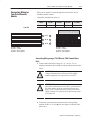
Methods of wiring the terminal base units are shown in the
illustration below.
Wiring the Terminal Base Units (1794ĆTB3G shown)
!
ATTENTION: Do not daisy chain power or
ground from the terminal base unit to any ac or dc
digital module terminal base unit.
DaisyĆchaining
.%, (.'- +
(.%
.%, (.'- +
(.%
&
(.%
.%, (.'- +
(.%
Note: %% &(.% , &.,- ).%, !+ *. '0 (+ & &(.% , !(+ -#$, ('!$".+-$('
Wiring when total current draw is less than 10A
Individual
$"$-% ').(.%
.%, (.'- +
(.%
$"$-% ').(.%
$"$-% .-).(.%
Note: , -#$, ('!$".+-$(' $! .,$'" '0
1'($,0 $"$-% &(.% , $' 0(.+ ,0,- &
Pulse Counter Module wiring separate from digital wiring.
Wiring when total current draw is greater than 10A
Combination
.%, (.'- +
(.%
.%, (.'- +
(.%
&
(.%
.%, (.'- +
(.%
Note: %% &(.% , )(/ + 0 -# ,& )(/ + ,.))%0
&.,- ).%, !+ *. '0 (+ & &(.% , !(+ -#$, ('!$".+-$('
Total current draw through any base unit must not be greater than 10A
.%$-$(' 2 .".,- 2–4
How to Install Your Pulse Counter Module
Installing the Module
Installation of the Pulse Counter module consists of:
• mounting the terminal base unit
• installing the module into the terminal base unit
• installing the connecting wiring to the terminal base unit
If you are installing your module into a terminal base unit that is
already installed, proceed to “Mounting the Pulse Counter Module
on the Terminal Base” on page 2–7.
Mounting the Terminal Base Unit on a DIN Rail
!
ATTENTION: Do not remove or replace a terminal
base unit when power is applied. Interruption of the
flexbus can result in unintended operation or machine
motion.
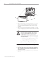
1. Remove the cover plug (if used) in the male connector of the unit
to which you are connecting this terminal base unit.
2. Check to make sure that the 16 pins in the male connector on the
adjacent device are straight and in line so that the mating female
connector on this terminal base unit will mate correctly.
3. Position the terminal base on the 35 x 7.5mm DIN rail A (A-B pt.
no. 199-DR1; 46277-3). Proceed as follows:
C
A
B
A
!$%! %# $ % $% !! !'# % %!"
! % #
4. Make certain that the female flexbus connector C is fully
retracted into the base unit.
&%! ( &&$% How to Install Your Pulse Counter Module
2–5
' '%!" & ("' #)% '' "&' ' $'%
&(% ' ## #" ' '%!" & & & ("% ' # '
$'% " ' +(& #""'#% & ( , %'%'
%&& #*" #" ' '%!" & ("' '# # ' '%!" & #" '
% ' '%!" & #& "#' # "'# $ (& &%*%)%
#% &! % ) '# #$" ' #" ' $%&& #*" #" ' '%!"
& ("' (& *' ' % " % & ' #" ' '# # '
& " $ 30077–M
$(& ' +(& #""'#% "'# ' &
# ' $'% '# #!$ ' ' $ " #""'#"
( '#" - ((&' 2–6
How to Install Your Pulse Counter Module
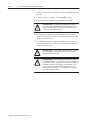
5. Repeat the above steps to install the next terminal base.
Panel/Wall Mounting
Installation on a wall or panel consists of:
•
•
•
•
laying out the drilling points on the wall or panel
drilling the pilot holes for the mounting screws
mounting the adapter mounting plate
installing the terminal base units and securing them to the wall or
panel
If you are installing your module into a terminal base unit that is
already installed, proceed to “Mounting the Pulse Counter Module
on the Terminal Base” on page2–7.
Use the mounting kit Cat. No. 1794-NM1 for panel/wall mounting.
1794ĆNM1 Mounting Kit
(', ',+
(-',$'" %, !(* ), *
+ %!/,))$'" +* .+
!(* ,# ), * ' # !(* -) ,( &(-% +
), * (-%
'(, $'%- *&$'% + '$,
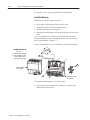
'(, $'%- To install the mounting plate on a wall or panel:
1. Lay out the required points on the wall/panel as shown in the
drilling dimension drawing.
-%$,$(' / -"-+, How to Install Your Pulse Counter Module
2–7
Drilling Dimensions for Panel/Wall Mounting of FLEX I/O
Inches
(Millimeters)
2. Drill the necessary holes for the #6 self-tapping mounting screws.
3. Mount the mounting plate (1) for the adapter module using two
#6 self-tapping screws (18 included for mounting up to 8 modules
and the adapter).
Important:
More
Make certain that the mounting plate is properly
grounded to the panel. Refer to “Industrial Automation
Wiring and Grounding Guidelines,” publication
1770-4.1.
4. Hold the adapter (2) at a slight angle and engage the top of the
mounting plate in the indention on the rear of the adapter module.
5. Press the adapter down flush with the panel until the locking lever
locks.
6. Position the terminal base unit up against the adapter and push the
female bus connector into the adapter.
7. Secure to the wall with two #6 self-tapping screws.
8. Repeat for each remaining terminal base unit.
Note: The adapter is capable of addressing eight modules. Do not
exceed a maximum of eight terminal base units in your system.
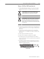
Mounting the Pulse Counter Module on the Terminal Base Unit
The Pulse Counter module mounts on a 1794-TB3, TB3S, -TBN or
-TBNF terminal base unit.
1. Rotate the keyswitch (1) on the terminal base unit (2) clockwise
to position 1 as required for the Pulse Counter module.
! " !! 2–8
How to Install Your Pulse Counter Module
2. Make certain the flexbus connector (3) is pushed all the way to
the left to connect with the neighboring terminal base/adapter.
You cannot install the module unless the connector is fully
extended.
3. Make sure that the pins on the bottom of the module are straight
so they will align properly with the connector in the terminal base
unit.
!
ATTENTION: Remove field-side power before
removing or inserting the module. This module is
designed so you can remove and insert it under
backplane power. When you remove or insert a
module with field-side power applied, an electrical arc
may occur. An electrical arc can cause personal injury
or property damage by:
• sending an erroneous signal to your system’s field
devices causing unintended machine motion
• causing an explosion in a hazardous environment
Repeated electrical arcing causes excessive wear to
contacts on both the module and its mating connector.
Worn contacts may create electrical resistance.
4. Position the module (4) with its alignment bar (5) aligned with
the groove (6) on the terminal base.
5. Press firmly and evenly to seat the module in the terminal base
unit. The module is seated when the latching mechanism (7) is
locked into the module.
6. Repeat the above steps to install the next module in its terminal
base unit.
How to Install Your Pulse Counter Module
Connecting Wiring for
Your Pulse Counter
Module
2–9
Wiring to the module is made through the terminal base unit on
which the module mounts.
Compatible terminal base units are:
Module
1794ĆTB3
1794ĆTB3S
1794ĆTBN
1794ĆTBNF
1794-IP4
Yes
Yes
Yes
Yes
1794ĆTB3
1794ĆTB3S
0 1 2 3 4 5 6 7 8 9 10 11 12 13 14 15
16 17 18 19 20 21 22 23 24 25 26 27 28 29 30 31 32 33
34 35 36 37 38 39 40 41 42 43 44 45 46 47 48 49 50 51
0
1 2 3 4 5
6 7
8 9 10 11 12 13 14 15
A
0 -15
A
B
16-33
B
C
34-51
C
16 17 18 19 20 21 22 23 24 25 26 27 28 29 30 31 32 33
34 35 36 37 38 39 40 41 42 43 44 45 46 47 48 49 50 51
$ ' '#$ # )%" %
" " #!!#"
" &&& %#("
'%( &&& %#("
" " #!!#"
" &&& %#("
'%( &&& %#("
Connecting Wiring using a 1794ĆTB3 and ĆTB3S Terminal Base
Units
1. Connect individual input wiring (N+, N–,) or (D+, D–) to
numbered terminals on the 0–15 row (A) as indicated in the table
below.
!
!
ATTENTION: Do not connect maximum input
voltage simultaneously to all inputs if the module
ambient temperature is expected to exceed 40oC.
ATTENTION: If the module ambient temperature is
expected to continuously exceed 40oC, you must limit
the input voltage using an external resistor on each
input. A 1KΩ resistor effectively limits a 24V sensor
signal to about 15V at the input. Do not limit the input
to less than 6V.
2. Connect the associated input common to the corresponding
terminal on the 16-33 row (B) for each input as indicated in the
table below.
( '#" *
((&' 2–10
How to Install Your Pulse Counter Module
3. If using shielded cable, terminate the shield at the DIN rail (earth
ground).
4. Connect +24V dc to terminal 34 on the 34-51 row (C).
5. Connect dc return to terminal 16 on the 16–33 row (B).
!
ATTENTION: To reduce susceptibility to noise,
power frequency modules and digital modules from
separate power supplies. Do not exceed a length of 33
ft (10m) for dc power cabling.
6. If continuing power to the next terminal base unit, connect a
jumper from terminal 51 (+24V dc) on this base unit to terminal
34 on the next base unit.
7. If continuing common to the next terminal base unit, connect a
jumper from terminal 33 (common) on this base unit to terminal
16 on the next base unit.
!
!
ATTENTION: Do not daisy chain power or ground
from this terminal base unit to any ac or dc digital
module terminal base unit.
ATTENTION: This module does not receive power
from the backplane. +24V dc power must be applied to
your module before operation. If power is not applied,
the module position will appear to the adapter as an
empty slot in your chassis. If the adapter does not
recognize your module after installation is completed,
cycle power to the adapter.
How to Install Your Pulse Counter Module
2–11
Wiring to a 1794ĆTBN or ĆTBNF Terminal Base Unit
1. Connect individual input wiring (N+, N–,) or (D+, D–) to the
even numbered terminals on row (B) as indicated in the table
below.
ATTENTION: Do not connect maximum input
voltage simultaneously to all inputs if the module
ambient temperature is expected to exceed 40oC.
!
ATTENTION: If the module ambient temperature is
expected to continuously exceed 40oC, you must limit
the input voltage using an external resistor on each
input. A 1KΩ resistor effectively limits a 24V sensor
signal to about 15V at the input. Do not limit the input
to less than 6V.
!
2. Connect the associated input common to the corresponding odd
numbered terminal on row (C) for each input as indicated in the
table below.
3. Connect the associated input common to the corresponding
terminal on the 16-33 row (B) for each input as indicated in the
table below.
4. Connect 24V dc to terminal 34 on row (C).
5. Connect 24V dc common to terminal 16 on row (B).
6. If continuing power to the next terminal base unit, connect a
jumper from terminal 51 (24V dc) on this base unit to terminal 34
on the next base unit.
7. If continuing common to the next terminal base unit, connect a
jumper from terminal 33 (24V dc common) on this base unit to
terminal 16 on the next base unit.
& %" " # $"% %" " # $"% 16, 0, 2, 4, 6,
8, 10, 12, 14, 33 B
34, 1, 3, 5, 7,
9, 11, 13, 15, 51
C
1794ĆTBN, ĆTBNF
%$! ' %%#$ 2–12
How to Install Your Pulse Counter Module
Wiring connections for the 1794-IP4 Pulse Counter Module
Channel
Terminal Base Units
1794-TB2, -TB3, -TB3S
Signal
Name1
Signal
0V dc
12/24V dc
(Common)
Terminal Base Units
1794-TBN, -TBNF2
Signal
Input
16-bit Period Time Measurement
32-bit Period Time Measurement
"!
,**,+
#.*'+)/ +" 6
#.*'+)/ 0&.1 6
6
#.*'+)/ +" "!
#.*'+)/ +" #.*'+)/ 0&.1 #.*'+)/ +" +5 1+1/#" /'%+)/ &2# 0, # !,++#!0#" 0, 0&# //,!'0#" !,**,+
14')'.5 0#.*'+) ),!(/ .# .#-1'.#" 3&#+ 1/'+% 0&#/# 0#.*'+) /# 1+'0/
NOTE: $ 1/'+% /&'#)"#" ! )# 0#.*'+0# 0&# /&'#)" 0 0&# .') #.0& %.,1+"
!
1 )'!0',+ 6 1%1/0 ATTENTION: Total current draw through the
terminal base unit is limited to 10A. Separate power
connections to the terminal base unit may be necessary.
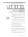
How to Install Your Pulse Counter Module
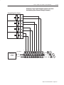
2–13
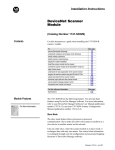
Example of 16-bit Period Time Measurement and 16-bit
Accumulating Pulse Counter Wiring (4 channels)
Accumulating Pulse Counter
Channel 3
N
N
Channel 2
N
N
Channel 1
N
N
Channel 0
N
N
"&%$
(%# !'#
&"")
A
B
C
&%! *
&&$% 2–14
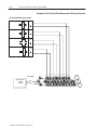
How to Install Your Pulse Counter Module
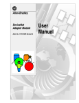
Example of 32-bit Period Time Measurement Wiring (4 channels)
32-bit period time measurement
Channel 3
D
D
Channel 2
D
D
Channel 1
D
D
Channel 0
D
D
"&%$
(%# !'#
&"")
&%! *
&&$% A
B
C
How to Install Your Pulse Counter Module
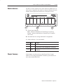
Module Indicators
2–15
The Pulse Counter module has one status indicator (PWR) that is on
when power is applied to the module, an input on indicator for each
channel, and an input status indicator for each input (8 in all).
4 CH PULSE COUNTER MODULE
C
B
A
A = Power/status indicator –
Red – indicates initialization of internal logic at powerup
Green – indicates initialization of internal logic is complete
and correct.
B = Insertable label for writing individual I/O assignments.
C = Status indicators – for each channel:
Indication Color
Chapter Summary
Description
")
! "! !&% & !#'& % &(
")
! "! !&% & !#'& % "!'$ "$ & #$" & %'$ !& ! & ' '&! #'% "'!&$ '!&"!
")
! "! !&% & !#'& % "!$'$ "$ & #$" & %'$ !&
In this chapter, we told you how to install your Pulse Counter
module in an existing programmable controller system and how to
wire to the terminal base units.
'&"! * ''%& What This Chapter
Contains
To initiate communication between the Pulse Counter module and
your PLC processor, you must enter block transfer instructions into
your ladder logic program. Use this chapter to enter the necessary
block transfer instructions into your ladder logic program.
To edit your ladder logic you
$(& "%! &$'& $'(&)( %$' + # "* &%''%&' + # "* &%''%&' + &%''%&' Enter Block Transfer
Instructions
See page
The Pulse Counter module communicates with the PLC processor
through bidirectional block transfers. This is the sequential
operation of both read and write block transfer instructions.
Before you configure the module, you need to enter block transfer
instructions into your ladder logic. The following example programs
illustrate the minimum programming required for communication to
take place between the module and a PLC processor. These
programs can be modified to suit your application requirements.
A configuration block transfer write (BTW) is initiated when the
module is first powered up, and subsequently only when the
programmer wants to enable or disable features of the module. The
configuration BTW sets the bits which enable the programmable
features of the module, such as scalars and alarm values, etc. Block
transfer reads are performed to retrieve information from the module.
Block transfer read (BTR) programming moves status and data from
the module to the processor’s data table. The processor user program
initiates the request to transfer data from the module to the processor.
The transferred words contain module status, channel status and
input data from the module.
Your program should monitor status bits, block transfer read and
block transfer write activity.
)" ( %$ +
))'(
3–2
Programming Your Pulse Counter Module
PLCĆ2 Family Processor
The 1794 Pulse Counter module is not recommended for use with
PLC-2 family programmable controllers due to the number of digits
needed for high resolution.
Important:
The Pulse Counter module functions with reduced
performance in PLC-2 systems. Because the module
does not support BCD and the PLC-2 processor is
limited to values of 4095 (12 bit binary), many values
returned in the BTR file may not provide meaningful
data to the PLC-2 processor.
PLCĆ5 Family Processor
Block transfer instructions with the PLC-5 processor use a control
file and a data file. The block transfer control file contains the data
table section for module location, the address of the block transfer
data file and other related data. The block transfer data file stores
data that you want transferred to the module (when programming a
BTW) or from the module (when programming a BTR).
The programming terminal prompts you to create a control file when
a block transfer instruction is being programmed. A different block
transfer control file is used for the read and write instructions
for your module.
Programming Your Pulse Counter Module
PLCĆ5 Processor
Program Example
3–3
60* !+( /1'6.( ,4 .1&$5(' ,0 3$&- *3162 4.15 !+( ,05(*(3 &10531. ),.( 45$354 $5 !+( '$5$ 4(05 %8 5+(
9 231&(4413 51 5+( /1'6.( 45$354 $5 $0' ,4 713'4 .10* 5 217(3 62 ,0 " /1'( 13 7+(0 5+(
231&(4413 ,4 ),345 47,5&+(' )31/ 51 " 5+( 64(3 231*3$/ (0$%.(4 $ %.1&- 53$04)(3 73,5( 51 &10),*63( 5+( /1'6.(
,345 4&$0 1)
.$''(3 13 !#
10531. ,.(
!#
! #!
1'6.( !82(
$&3162
.15
10531.
$5$,.(
(0*5+
105,06164
(0(3,& !
60* !+( /1'6.( ,4 .1&$5(' ,0 3$&- *3162 4.15 !+( ,05(*(3 &10531. ),.( 45$354 $5 !+( '$5$ 1%5$,0(' %8 5+(
9 231&(4413 )31/ 5+( /1'6.( ,4 2.$&(' ,0 /(/138 45$35,0* $5 $0' ,4 713'4 .10* .!+( 231*3$/
&105,06164.8 2(3)13/4 3($' %.1&- 53$04)(34 51 3($' '$5$ )31/ 5+( /1'6.(
!
0$%.( ,5
SLCĆ5 Programming
!
10531. ,.(
!
! 1'6.( !82(
$&3162
.15
10531.
$5$,.(
(0*5+
105,06164
(0(3,& !
The SLC-5 programs (using the 1747-SN scanner) follow the same
logic as the PLC-5 family programs in the previous example.
Differences occur in the implementation of block transfers due to the
use of “M” files in the SLC system.
Configuration data for the FLEX I/O Pulse Counter module and the
1747-SN scanner must be in place before executing the following
programs. Chapter 4 contains information on module configuration.
For more information on using the 1747-SN scanner module and
block transfer programming, refer to publication 1747-6.6, “Remote
I/O Scanner User Manual.”
6%.,&$5,10 9" 6*645 3–4
Programming Your Pulse Counter Module
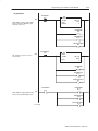
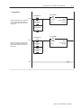
Figure 3.1
SLC Programming for the 1794ĆIP4 Pulse Counter Module
The 1794ĆIP4 module is located in remote I/O rack 1, group 0, slot 0. The 1747ĆSN scanner module is located in slot 1 of the SLC chassis. This program enables
1 BTW to configure the 1794ĆIP4 module at powerĆup. Thereafter, BTrs will be performed continuously to obtain data from the 1794ĆIP4 module.
Program Action
0000
PowerUp Bit
S2:1
15
This rung configures the block transfer operation
type, length, and RIO address at powerĆup. Bit
B3:100/7 must be set to 1 to indicate a BTR and
bit B3:110/7 must be 0 to indicate a BTW.
BTR_CONTROL
COP
COPY FILE
SOURCE
DEST
LENGTH
#B3:100
#M0:1.100
3
BTW_CONTROL
COP
COPY FILE
SOURCE
DEST
LENGTH
#B3:110
#M0:1.200
3
TRIGGER FOR BTW
N7:20
0
0001
BTR status is copied to the B3:0 area when a BTR
is in progress.
BTR PENDING
B3:5
0
CHECK BTR STATUS
B3:5
COP
COPY FILE
SOURCE
DEST
LENGTH
#M1:1.100
#B3:0
4
1
CHECK BTR STATUS
B3:5
BTR DONE BIT
B3:0
0002
Unlatch the bit that continues to check the BTR status.
U
13
1
BTR ERROR BIT
B3:0
12
0003
BTW status is copied to the B3:100 area when a
BTW is in progress.
BTW PENDING
B3:15
0
CHECK BTW STATUS
B3:15
COP
COPY FILE
SOURCE
DEST
LENGTH
#M1:1.200
#B3:10
4
1
0004
BTW DONE BIT
B3:10
13
Unlatch the bit that continues to check the BTW status.
BTW ERROR BIT
B3:10
To next page.
Publication 1794ĆUM016B-EN-P - August 2002
12
CHECK BTW STATUS
B3:15
U
1
Programming Your Pulse Counter Module
3–5
Program Action
0005
" "
%.+2 ' " 68))+66,800; )3140+7+6 '2* 7.+
*32+ (/7 /6 *+7+)7+* 7.+ " *'7' /6 )34/+*
/273 7.+ 73 '5+'
&
!# !"
"
" #
" "
#
" !""#!
%.+ ' " +5535 3))856 7.+ +5535 )3*+ /6
139+* 73 0006
" "
$
$
!# !"
" #
" "
#
" !""#!
%.+2 ' "% 68))+66,800; )3140+7+6 '2* 7.+
*32+ (/7 /6 *+7+)7+* '00 "% ,0'-6 '5+ 5+6+7
0007
"%"
"3 2+:7 4'-+
"%
#
"%"
#
"%!""#!
8(0/)'7/32 <# 8-867 3–6
Programming Your Pulse Counter Module
Program Action
%.+2 ' "% 3))856 7.+ +5535 )3*+ /6 139+*
73 0008
"% "
$
$
!# !"
"%
#
"%"
#
"%!""#!
0009
" "
" "
"./6 582- +;+)87+6 " 6 )327/283860< '6 ,'67
'6 4366/(0+
" "
" " "
0010
2+ "% /6 75/--+5+* '7 43:+5 84 ".5++ :35*6
3, *'7' 67'57/2- '7 /6 6+27 73 7.+ =
13*80+
" "%
"%
"
"%
"
"%
"
&
!# !"
"
"%"
"%
"3 2+;7 4'-+
8(0/)'7/32 =# 8-867 Programming Your Pulse Counter Module
3–7
Program Action
0011
)*1 $.-20.+ 5.0% *1 ,.4&% 2. 2)& '*+&
'.0 2)& 1$"--&0 ,.%3+& 5)*+& 2)& *1 */0.(0&11 3-2*+ 2)& &-"#+& %.-& "-% &00.0 #*21
"0& 230-&% .''
0012
!
)*1 ! $.-20.+ 5.0% *1 ,.4&% 2. 2)& '*+&
'.0 2)& 1$"--&0 ,.%3+& 5)*+& 2)& ! *1 */0.(0&11 3-2*+ 2)& &-"#+& %.-& "-% &00.0 #*21
"0& 230-&% .''
!
! !
0013
3#+*$"2*.- 6 3(312 3–8
Programming Your Pulse Counter Module
Chapter Summary
In this chapter, you learned how to program your 1794-IP4 Pulse
Counter module using block transfer instructions and ladder logic.
Now, you can configure your module.
" !
"
"! # "" ! Writing Configuration to and
Reading Status from Your
Module with a Remote I/O
Adapter
What This Chapter
Contains
Configuring Your Pulse
Counter Module
In this chapter, we tell you about:
For information on
See page
+*#&$0-&*$ +0- +!0(" "!&*$ / #-+) +0- +!0(" ,,&*$ / #+- /%" +!0(" 0(." +0*/"- +!0(" 1 )$" (" ,,&*$ (+ ' -*.#"- "! +-! ..&$*)"*/. &/+-! "#&*&/&+*. #+- (+ ' -*.#"- "! +-!. (+ ' -*.#"- -&/" +-! ..&$*)"*/. &/+-! "#&*&/&+*. #+- /%" (+ ' -*.#"- -&/" +-!. The Pulse Counter module is configured using a group of data table
words that are transferred to the module using a block transfer write
instruction.
Some of the software configurable features available are:
•
•
•
•
•
number of inputs
encoder multiplier
gate function
latch function
rollover
Configure your module for its intended operation by means of your
programming terminal and write block transfers.
Note: Programmable controllers that use 6200 software (release 4.2
or higher) programming tools can take advantage of the IOCONFIG
Addendum utility to configure this module. IOCONFIG Addendum
uses menu–based screens for configuration without having to set
individual bits in particular locations. Refer to your 6200 software
literature for details.
Important:
It is strongly recommended that you use IOCONFIG
Addendum to configure this module. The IOCONFIG
Addendum utility greatly simplifies configuration. If
the IOCONFIG Addendum is not available, you must
enter data directly into the data table. Use this chapter
as a reference when performing this task.
0(& /&+* 1 0$0./
4–2
Writing Configuration to and Reading Status from Your Module with a Remote I/O Adapter
During normal operation, the processor transfers from 1 to 4 words
to the module when you program a BTW instruction to the module’s
address.
Reading Data From Your
Module
Read programming moves status and data from the Pulse Counter
module to the processor’s data table in one I/O scan. The processor’s
user program initiates the request to transfer data from the Pulse
Counter module to the processor.
Mapping Data for the
Module
The following read and write words and bit/word descriptions
describe the information written to and read from the Pulse Counter
module. The module uses up to 11 words of input data and up to 3
words of output data. Each word is composed of 16 bits.
Pulse Counter Module (1794ĆIP4) Image Table Mapping
Module Image
I/O Image
Input Size
Counter 00 - 16-bit period measurement or low word of 32Ćbit period measurement for channel 0
Counter 01 - pulse counter for channel 0 or high word of 32Ćbit period measurement
Counter 10 - 16-bit period measurement or low word of 32Ćbit period measurement for channel 1
Counter 11 - pulse counter for channel 1 or high word of 32Ćbit period measurement
Counter 20 - 16-bit period measurement or low word of 32Ćbit period measurement for channel 2
Counter 21 - pulse counter for channel 2 or high word of 32Ćbit period measurement
Counter 30 - 16-bit period measurement or low word of 32Ćbit period measurement for channel 3
Counter 31 - pulse counter for channel 3 or high word of 32Ćbit period measurement
Readback of Control word 2 or
Reserved
RD3 RD2 RD1 RD0 M3
M2 M1 M0
Code for identification of software version
Output Size
Control Word 0 - Sets the measure function
Control Word 1 - Sets the clock frequency and period multiple
Control Word 2 - sets the start of a new measurement
Writing Configuration to and Reading Status from Your Module with a Remote I/O Adapter
4–3
Block Transfer Read Word Assignments for the Pulse Counter
Module (1794-IP4)
(Octal Bit⇒)
17
16
15
14
13
12
11
10
07
06
05
04
03
02
01
00
Dec. Bit ⇒
15
14
13
12
11
10
09
08
07
06
05
04
03
02
01
00
Word⇓
Read
*/).!, %. +!,%* (!-/,!(!). *, '*1 1*, *" 3%. +!,%* (!-/,!(!). "*, $))!' */).!, +/'-! */).!, *, $%#$ 1*, *" 3%. +!,%* (!-/,!(!). "*, $))!' */).!, %. +!,%* (!-/,!(!). *, '*1 1*, *" 3%. +!,%* (!-/,!(!). "*, $))!' */).!, +/'-! */).!, *, $%#$ 1*, *" 3%. +!,%* (!-/,!(!). "*, $))!' */).!, %. +!,%* (!-/,!(!). *, '*1 1*, *" 3%. +!,%* (!-/,!(!). "*, $))!' */).!, +/'-! */).!, *, $%#$ 1*, *" 3%. +!,%* (!-/,!(!). "*, $))!' */).!, %. +!,%* (!-/,!(!). *, '*1 1*, *" 3%. +!,%* (!-/,!(!). "*, $))!' */).!, +/'-! */).!, *, $%#$ 1*, *" 3%. +!,%* (!-/,!(!). "*, $))!' ! & *" *).,*' *, !-!,0!
!0%-%*) ,! -*".1,! 0!,-%*) * !
$!,! +*-%.%0! ! #! (!-/,!(!). ,! 2 "*, .$! ,!-+!.%0! $))!'
!-!. *)! "*, .$! ,!-+!.%0! $))!'
Bit/Word Definitions for Block Transfer Read Words for the
Pulse Counter Module
Read
Word
Bit
%.- %.- %.- %.- %.- %.- %.- %.- Definition
Store Counter 00 %. +!,%* (!-/,!(!). *, '*1 1*, *" 3%. +!,%* (!-/,!(!). "*, $))!' Counter 01 +/'-! */).!, *, $%#$ 1*, *" 3%. +!,%* (!-/,!(!). "*, $))!' Counter 10 %. +!,%* (!-/,!(!). *, '*1 1*, *" 3%. +!,%* (!-/,!(!). "*, $))!' Counter 11 +/'-! */).!, *, $%#$ 1*, *" 3%. +!,%* (!-/,!(!). "*, $))!' Counter 20 %. +!,%* (!-/,!(!). *, '*1 1*, *" 3%. +!,%* (!-/,!(!). "*, $))!' Counter 21 +/'-! */).!, *, $%#$ 1*, *" 3%. +!,%* (!-/,!(!). "*, $))!' Counter 30 %. +!,%* (!-/,!(!). *, '*1 1*, *" 3%. +!,%* (!-/,!(!). "*, $))!' Counter 31 +/'-! */).!, *, $%#$ 1*, *" 3%. +!,%* (!-/,!(!). "*, $))!' /'%.%*) 3 /#/-. 4–4
Writing Configuration to and Reading Status from Your Module with a Remote I/O Adapter
Read
Word
Bit
Definition
Readback of Control Word 2
'* '* ", Positive edge - Channel 0 %+-*%&, *0
", Positive edge - Channel 1 %+-*%&, *0
", Positive edge - Channel 2 %+-*%&, *0
", Positive edge - Channel 3 %+-*%&, *0
", Reset Done, Channel 0 - ('+",". '& ,!"+ ", "&",+ '-&,* *+, '&
", Reset Done, Channel 1 - ('+",". '& ,!"+ ", "&",+ '-&,* *+, '&
", Reset Done, Channel 2 - ('+",". '& ,!"+ ", "&",+ '-&,* *+, '&
", Reset Done, Channel 3 - ('+",". '& ,!"+ ", "&",+ '-&,* *+, '&
", +*. '* ,'*0 -+
",+ ',/* *."+"'& .*+"'& ' ' +',/* "&+,$$
Block Transfer Write Word Assignments for the Pulse Counter
Module
(Octal Bit) ⇒
17
16
15
14
13
12
11
10
07
06
05
04
03
02
01
00
Dec. Bit ⇒
15
14
13
12
11
10
09
08
07
06
05
04
03
02
01
00
Word⇓
Write
'&,*'$ '* +$,+ ,! %+-* -&,"'&
'&,*'$ '* +,+ ,! $'# *)-&0 & (*"' %-$,"($
'&,*'$ '* +,+ ,! +,*, ' &/ %+-*%&,
', -+
-$","'& 1 - -+, Writing Configuration to and Reading Status from Your Module with a Remote I/O Adapter
4–5
Bit/Word Definitions for the Block Transfer Write Words for the Pulse
Counter Module
Write
Word
-&/"
+-! Bit
Control Word 0 - +*/-+( 2+-! #+- ."//&*$ /%" #0* /&+* +# +0*/"- &/. 0(." +0*/&*$ *! ,"-&+! /&)" )".0-")"*/ ."(" /&+* #+- %**"( ,0(." +0*/&*$ *! ,"-&+! /&)" )".0-")"*/ ."(" /"!
,"-&+! /&)" )".0-")"*/ ."(" /"!
&/. 0(." +0*/&*$ *! ,"-&+! /&)" )".0-")"*/ ."(" /&+* #+- %**"( ,0(." +0*/&*$ *! ,"-&+! /&)" )".0-")"*/ ."(" /"!
,"-&+! /&)" )".0-")"*/ ."(" /"!
&/. 0(." +0*/&*$ *! ,"-&+! /&)" )".0-")"*/ ."(" /&+* #+- %**"( ,0(." +0*/&*$ *! ,"-&+! /&)" )".0-")"*/ ."(" /"!
,"-&+! /&)" )".0-")"*/ ."(" /"!
&/. 0(." +0*/&*$ *! ,"-&+! /&)" )".0-")"*/ ."(" /&+* #+- %**"( ,0(." +0*/&*$ *! ,"-&+! /&)" )".0-")"*/ ."(" /"!
,"-&+! /&)" )".0-")"*/ ."(" /"!
&/. -&/"
+-! "."-1"!
Control Word 1 - +*/-+( 2+-! #+- ."//&*$ ,"-&+! )".0-")"*/
&/ &/. &/ -&/"
+-! Definition
Clock frequency for period time measurement - Channel 0 ,"-&+! /&)" )".0-")"*/ 2&/% 3 &*/"-*( (+ ' ."(" /"!
,"-&+! /&)" )".0-")"*/ 2&/% 3 &*/"-*( (+ ' ."(" /"!
0)"- +# ,"-&+!. #+- )".0-")"*/ %**"( ,"-&+!
,"-&+!.
,"-&+!.
,"-&+!.
,"-&+!.
,"-&+!.
,"-&+!.
,"-&+!.
Clock frequency for period time measurement - Channel 1 -"#"- /+ &/ &/. "(" /&+* +# 0)"- +# ,"-&+!. #+- )".0-")"*/ %**"( ."" &/. +1"
&/ Clock frequency for period time measurement - Channel 2 -"#"- /+ &/ &/. "(" /&+* +# 0)"- +# ,"-&+!. #+- )".0-")"*/ %**"( ."" &/. +1"
&/ Clock frequency for period time measurement - Channel 1 -"#"- /+ &/ &/. "(" /&+* +# 0)"- +# ,"-&+!. #+- )".0-")"*/ %**"( ."" &/. +1"
Control Word 2 - ./-/. *"2 )".0-")"*/
&/ Start new measurement bit - Channel 0 2%"* ."/ ./-/ *"2 )".0-")"*/ +* ,+.&/&1" "!$"
&/ Start new measurement bit - Channel 1 2%"* ."/ ./-/ *"2 )".0-")"*/ +* ,+.&/&1" "!$"
&/ Start new measurement bit - Channel 2 2%"* ."/ ./-/ *"2 )".0-")"*/ +* ,+.&/&1" "!$"
&/ Start new measurement bit - Channel 3 2%"* ."/ ./-/ *"2 )".0-")"*/ +* ,+.&/&1" "!$"
0(& /&+* 4 0$0./ 4–6
Write
Word
$&
"$ "!&&
"
$&
"$% ! Writing Configuration to and Reading Status from Your Module with a Remote I/O Adapter
Bit
Definition
& Reset Counter, Channel 0 - #"%&( "! &% & $%&% "'!&$ & Reset Counter, Channel 1 - #"%&( "! &% & $%&% "'!&$ & Reset Counter, Channel 2 - #"%&( "! &% & $%&% "'!&$ & Reset Counter, Channel 3 - #"%&( "! &% & $%&% "'!&$ & "& '%
& "& '%
Chapter Summary
' &"! ) ''%& In this chapter, you learned how to configure your module’s features
and enter your data.
How Communication Takes
Place and I/O Image Table
Mapping with the DeviceNet
Adapter
What This Chapter
Contains
In this chapter, we tell you about:
About DeviceNetManager
Software
For information on
See page
+0/ #1'!##/*%#- +$/2-# +((#" /-0!/0-# ",/#- *,0/ //0. +-" 3./#) &-+0%&,0/ ,,'*% / '*/+ /&# )%# (# 0(.# +0*/#- +"0(# 4 )%# (# ,,'*% 0(.# +0*/#- '/+-" ..'%*)#*/. #$0(/. DeviceNetManager software is a tool used to configure your FLEX
I/O DeviceNet adapter and its related modules. This software tool
can be connected to the adapter via the DeviceNet network.
You must understand how DeviceNetManager software works in
order to add a device to the network. Refer to the DeviceNetManager
Software User Manual, publication 1787-6.5.3.
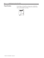
Polled I/O Structure
Output data is received by the adapter in the order of the installed
I/O modules. The Output data for Slot 0 is received first, followed
by the Output data for Slot 1, and so on up to slot 7.
The first word of input data sent by the adapter is the Adapter Status
Word. This is followed by the input data from each slot, in the order
of the installed I/O modules. The Input data from Slot 0 is first after
the status word, followed by Input data from Slot 2, and so on up to
slot 7.
DeviceNet Adapter
Read Data
Network READ
",/#- //0.
(+/ *,0/ /
(+/ *,0/ /
(+/ *,0/ /
Write Data
I/O Module
Slot 7
(+/ 0/,0/ /
(+/ 0/,0/ /
Network WRITE
#" I/O Module I/O Module
Slot 0
Slot 1
-'/#
(+/ 0/,0/ /
0 ('!/'+* 4 0%0./ 5–2
How Communication Takes Place and I/O Image Table Mapping with the DeviceNet Adapter
Adapter Input Status Word
The input status word consists of:
• I/O module fault bits – 1 status bit for each slot
• node address changed – 1 bit
• I/O status – 1 bit
*#/($ /(. '.(*.
(*.
(*.
*. -$#
(*.
(*.
(*.
.&,*/%& (*.
(*.
'.
. .$ '.
*#$ ##,$-- & )%$# '.
The adapter input status word bit descriptions are shown in the
following table.
Bit Description
Bit
Explanation
&'- !'. '- -$. 0&$) ) $,,*, '- #$.$".$# ') -(*. +*-'.'*) &'- !'. '- -$. 0&$) ) $,,*, '- #$.$".$# ') -(*. +*-'.'*) &'- !'. '- -$. 0&$) ) $,,*, '- #$.$".$# ') -(*. +*-'.'*) &'- !'. '- -$. 0&$) ) $,,*, '- #$.$".$# ') -(*. +*-'.'*) &'- !'. '- -$. 0&$) ) $,,*, '- #$.$".$# ') -(*. +*-'.'*) &'- !'. '- -$. 0&$) ) $,,*, '- #$.$".$# ') -(*. +*-'.'*) &'- !'. '- -$. 0&$) ) $,,*, '- #$.$".$# ') -(*. +*-'.'*) &'- !'. '- -$. 0&$) ) $,,*, '- #$.$".$# ') -(*. +*-'.'*) *#$ ##,$-- & )%$#
&'- !'. '- -$. 0&$) .&$ )*#$ ##,$-- -0'."& -$..')% & - !$$)
"& )%$# -')"$ +*0$, /+
. .$
'. '#($
'. ,/)
*#/($ /(.
.&,/ *. /-$# -$). - 1$,*$-
Possible causes for an I/O Module Fault are:
•
•
•
•
•
transmission errors on the Flex I/O backplane
a failed module
a module removed from its terminal base
incorrect module inserted in a slot position
the slot is empty
The node address changed bit is set when the node address switch
setting has been changed since power up. The new node address does
not take affect until the adapter has been powered down and then
powered back up.
/!('" .'*) 2 /%/-. How Communication Takes Place and I/O Image Table Mapping with the DeviceNet Adapter
System Throughput
5–3
System throughput, from Pulse Counter to backplane, is a function
of:
• the configured minimum frequency sample time
• the number of channels actually configured for connection to a
specific sensor (0 or 1)
You can set the minimum frequency time during module
configuration. The selection influences the sample data rate, thus
affecting system throughput.
The number of channels included in each input scan also affects
system throughput.
Mapping Data into the
Image Table
FLEX I/O Pulse Counter module data table mapping is shown
below.
Pulse Counter Module (1794ĆIP4) Image Table Mapping
Module Image
I/O Image
Input Size
Counter 00 - 16-bit period measurement or low word of 32Ćbit period measurement for channel 0
Counter 01 - pulse counter for channel 0 or high word of 32Ćbit period measurement
Counter 10 - 16-bit period measurement or low word of 32Ćbit period measurement for channel 1
Counter 11 - pulse counter for channel 1 or high word of 32Ćbit period measurement
Counter 20 - 16-bit period measurement or low word of 32Ćbit period measurement for channel 2
Counter 21 - pulse counter for channel 2 or high word of 32Ćbit period measurement
Counter 30 - 16-bit period measurement or low word of 32Ćbit period measurement for channel 3
Counter 31 - pulse counter for channel 3 or high word of 32Ćbit period measurement
Readback of Control word 2 or
Reserved
RD3 RD2 RD1 RD0 M3
M2 M1 M0
Code for identification of software version
Output Size
Control Word 0 - Sets the measure function
Control Word 1 - Sets the clock frequency and period multiple
Control Word 2 - sets the start of a new measurement
Reserved
Reserved
5–4
How Communication Takes Place and I/O Image Table Mapping with the DeviceNet Adapter
Block Transfer Read Word Assignments for the Pulse Counter
Module (1794-IP4)
(Octal Bit⇒)
17
16
15
14
13
12
11
10
07
06
05
04
03
02
01
00
Dec. Bit ⇒
15
14
13
12
11
10
09
08
07
06
05
04
03
02
01
00
Word⇓
Read
*0)/!- %/ +!-%* (!.0-!(!)/ *- '*2 2*- *" 4%/ +!-%* (!.0-!(!)/ "*- $))!' *0)/!- +0'.! *0)/!- *- $%#$ 2*- *" 4%/ +!-%* (!.0-!(!)/ "*- $))!' *0)/!- %/ +!-%* (!.0-!(!)/ *- '*2 2*- *" 4%/ +!-%* (!.0-!(!)/ "*- $))!' *0)/!- +0'.! *0)/!- *- $%#$ 2*- *" 4%/ +!-%* (!.0-!(!)/ "*- $))!' *0)/!- %/ +!-%* (!.0-!(!)/ *- '*2 2*- *" 4%/ +!-%* (!.0-!(!)/ "*- $))!' *0)/!- +0'.! *0)/!- *- $%#$ 2*- *" 4%/ +!-%* (!.0-!(!)/ "*- $))!' *0)/!- %/ +!-%* (!.0-!(!)/ *- '*2 2*- *" 4%/ +!-%* (!.0-!(!)/ "*- $))!' *0)/!- +0'.! *0)/!- *- $%#$ 2*- *" 4%/ +!-%* (!.0-!(!)/ "*- $))!' ! & *" *)/-*' *- !.!-1!
!1%.%*) -! .*"/2-! 1!-.%*) * !
$!-! +*.%/%1! ! #! (!.0-!(!)/ -! 3 "*- /$! -!.+!/%1! $))!'
!.!/ *)! "*- -!.+!/%1! $))!'
Block Transfer Write Word Assignments for the Pulse Counter
Module
(Octal Bit) ⇒
17
16
15
14
13
12
11
10
07
06
05
04
03
02
01
00
Dec. Bit ⇒
15
14
13
12
11
10
09
08
07
06
05
04
03
02
01
00
Word⇓
Write
*)/-*' *- .!'!/. /$! (!.0-! "0)/%*)
*)/-*' *- .!/. /$! '*& "-!,0!)3 ) +!-%* (0'/%+'!
*)/-*' *- .!/. /$! ./-/ *" )!2 (!.0-!(!)/
!.!-1!
Bit/Word Definitions for the Pulse Counter Module
Word
Bit
!
*- %/. !
*- %/. !
*- %/. !
*- %/. !
*- %/. Definition
Store Counter 00 %/ +!-%* (!.0-!(!)/ *- '*2 2*- *" 4%/ +!-%* (!.0-!(!)/ "*- $))!' Counter 01 +0'.! *0)/!- *- $%#$ 2*- *" 4%/ +!-%* (!.0-!(!)/ "*- $))!' Counter 10 %/ +!-%* (!.0-!(!)/ *- '*2 2*- *" 4%/ +!-%* (!.0-!(!)/ "*- $))!' Counter 11 +0'.! *0)/!- *- $%#$ 2*- *" 4%/ +!-%* (!.0-!(!)/ "*- $))!' Counter 20 %/ +!-%* (!.0-!(!)/ *- '*2 2*- *" 4%/ +!-%* (!.0-!(!)/ "*- $))!' 0'%/%*) 4 0#0./ How Communication Takes Place and I/O Image Table Mapping with the DeviceNet Adapter
Word
Bit
') #+* ') #+* ') #+* ') ') )#+
') 5–5
Definition
Counter 21 (,$* ',&+) ') "#!" .') ' 0#+ ()#' %*,)%&+ ') "&&$ Counter 30 #+ ()#' %*,)%&+ ') $'. .') ' 0#+ ()#' %*,)%&+ ') "&&$ Counter 31 (,$* ',&+) ') "#!" .') ' 0#+ ()#' %*,)%&+ ') "&&$ Readback of Control Word 2
#+ Positive edge - Channel 0 %*,)%&+ )/
#+ Positive edge - Channel 1 %*,)%&+ )/
#+ Positive edge - Channel 2 %*,)%&+ )/
#+ Positive edge - Channel 3 %*,)%&+ )/
#+ Reset Done, Channel 0 - ('*#+#- ! '& +"#* #+ #&#+* ',&+) )*+ '&
#+ Reset Done, Channel 1 - ('*#+#- ! '& +"#* #+ #&#+* ',&+) )*+ '&
#+ Reset Done, Channel 2 - ('*#+#- ! '& +"#* #+ #&#+* ',&+) )*+ '&
#+ Reset Done, Channel 3 - ('*#+#- ! '& +"#* #+ #&#+* ',&+) )*+ '&
#+ *)- ') +')/ ,*
#+* Software revision -)*#'& ' ' *' +.) #&*+$$
Control Word 0 - '&+)'$ .') ') *++#&! +" ,&+#'& ' ',&+) #+* Pulse counting and period time measurement selection for Channel 0 (,$* ',&+#&! & ()#' +#% %*,)%&+ *$+
()#' +#% %*,)%&+ *$+
#+* Pulse counting and period time measurement selection for Channel 1 (,$* ',&+#&! & ()#' +#% %*,)%&+ *$+
()#' +#% %*,)%&+ *$+
#+* Pulse counting and period time measurement selection for Channel 2 (,$* ',&+#&! & ()#' +#% %*,)%&+ *$+
()#' +#% %*,)%&+ *$+
#+* Pulse counting and period time measurement selection for Channel 3 (,$* ',&+#&! & ()#' +#% %*,)%&+ *$+
()#' +#% %*,)%&+ *$+
#+* *)-
,$#+#'& 0 ,!,*+ 5–6
How Communication Takes Place and I/O Image Table Mapping with the DeviceNet Adapter
Word
Bit
-&/"
+-! &/ &/. &/ -&/"
+-! -&/"
+-!. *! Definition
Clock frequency for period time measurement - Channel 0 ,"-&+! /&)" )".0-")"*/ 2&/% 3 &*/"-*( (+ ' ."(" /"!
,"-&+! /&)" )".0-")"*/ 2&/% 3 &*/"-*( (+ ' ."(" /"!
0)"- +# ,"-&+!. #+- )".0-")"*/ %**"( ,"-&+!
,"-&+!.
,"-&+!.
,"-&+!.
,"-&+!.
,"-&+!.
,"-&+!.
,"-&+!.
Clock frequency for period time measurement - Channel 1 -"#"- /+ &/ &/. "(" /&+* +# 0)"- +# ,"-&+!. #+- )".0-")"*/ %**"( ."" &/. +1"
&/ Clock frequency for period time measurement - Channel 2 -"#"- /+ &/ &/. "(" /&+* +# 0)"- +# ,"-&+!. #+- )".0-")"*/ %**"( ."" &/. +1"
&/ Clock frequency for period time measurement - Channel 1 -"#"- /+ &/ &/. "(" /&+* +# 0)"- +# ,"-&+!. #+- )".0-")"*/ %**"( ."" &/. +1"
&/ Start new measurement bit - Channel 0 2%"* ."/ ./-/ *"2 )".0-")"*/ +* ,+.&/&1" "!$"
&/ Start new measurement bit - Channel 1 2%"* ."/ ./-/ *"2 )".0-")"*/ +* ,+.&/&1" "!$"
&/ Start new measurement bit - Channel 2 2%"* ."/ ./-/ *"2 )".0-")"*/ +* ,+.&/&1" "!$"
&/ Start new measurement bit - Channel 3 2%"* ."/ ./-/ *"2 )".0-")"*/ +* ,+.&/&1" "!$"
&/ Reset Counter, Channel 0 - ,+.&/&1" "!$" +* /%&. &/ -"."/. +0*/"- &/ Reset Counter, Channel 1 - ,+.&/&1" "!$" +* /%&. &/ -"."/. +0*/"- &/ Reset Counter, Channel 2 - ,+.&/&1" "!$" +* /%&. &/ -"."/. +0*/"- &/ Reset Counter, Channel 3 - ,+.&/&1" "!$" +* /%&. &/ -"."/. +0*/"- &/ "."-1"!
&/ "."-1"!
0(& /&+* 4 0$0./ How Communication Takes Place and I/O Image Table Mapping with the DeviceNet Adapter
Defaults
5–7
Each I/O module has default values associated with it. At default,
each module will generate inputs/status and expect
outputs/configuration.
Module Defaults for:
Catalog
Number
"
Description
! ! !
Factory Defaults
Real Time Size
Input
Default
Output
Default
Input
Default
Output
Default
Factory defaults are the values assigned by the adapter when you:
• first power up the system, and
• no previous stored settings have been applied.
For Pulse Counter modules, the defaults reflect the actual number of
input words/output words. For example, for the Pulse Counter
module, you have 10 input words, and 5 output words.
You can change the I/O data size for a module by reducing the
number of words mapped into the adapter module, as shown in “real
time sizes.”
Real time sizes are the settings that provide optimal real time data to
the adapter module.
The Pulse Counter modules have 15 words assigned to them. This is
divided into input words/output words. You can reduce the I/O data
size to fewer words to increase data transfer over the backplane.
For information on using DeviceNetManager software to configure
your adapter, refer to the DeviceNetManager Software User Manual,
publication 1787-6.5.3.
! " !! 5–8
How Communication Takes Place and I/O Image Table Mapping with the DeviceNet Adapter
Input, Output and
Configuration Files for Analog
Modules when used with
ControlNet
Chapter Objectives
In this chapter you will learn about:
•
•
•
•
•
•
About the ControlNet
Adapter
Communication Over the
FLEX I/O Backplane
ControlNet Adapter
I/O structure
safe state data
communication fault data
idle state behavior
input data behavior upon module removal
The FLEX I/O ControlNet adapters (cat. no. 1794–ACN15 and
–ACNR15) interfaces up to 8 FLEX I/O modules and a ControlNet
processor or scanner. The adapter can support ControlNet real–time
data connections to individual modules or module groups. Each
connection is independent of the others and can be from different
processors or scanners.
One 1794-ACN15 and -ACNR15 ControlNet adapter can interface
up to eight terminal base units with installed FLEX I/O modules,
forming a FLEX I/O system of up to eight slots. The adapter
communicates to other network system components (typically one or
more controllers or scanners, and/or programming terminals) over
the ControlNet network. The adapter communicates with its I/O
modules over the backplane.
I/O Module
!#'&%
Network
ControlNet
Adapter
$&
"$%
&&'%
'&#'&%
"!'$&"!
Slot 0
I/O Module
$&
"$%
I/O Module
!#'&%
!#'&%
&&'%
&&'%
'&#'&%
'&#'&%
"!'$&"!
"!'$&"!
Slot 1
Slot 7
Data is exchanged scheduled (when mapped) or unscheduled (using
CIO instructions).
' &"! ( ''%& 6–2
Input, Output and Configuration Files for Analog Modules when used with ControlNet
Scheduled DataĆTransfer
Scheduled data transfer:
• is continuous
• is asynchronous to the ladder-logic program scan
• occurs at the actual rate displayed in the Actual Packet Interval
field on the programming software ControlNet I/O mapping
(monitor) screen
Unscheduled DataĆTransfer
Unscheduled operations include:
• unscheduled non-discrete I/O data transfers—through ControlNet
I/O Transfer (CIO) instructions
• peer-to-peer messaging—through Message (MSG) instructions
• messaging from programming devices
Unscheduled messaging on a ControlNet network is
non-deterministic. Your application and your configuration—number
of nodes, application program, NUT, amount of scheduled bandwidth
used, etc.—determine how much time there is for
unscheduled messaging.
Module I/O Mapping
The I/O map for a module is divided into read words and write
words. Read words consist of input and status words, and write
words consist of output and configuration words. The number of
read words or write words can be 0 or more. The length of each I/O
module’s read words and write words vary in size depending on
module complexity. Each I/O module will support at least 1 input
word or 1 output word. Status and configuration are optional,
depending on the module.
For example, a 16 point discrete input module will have up to 2 read
words and 1 write word.
ControlNet Image
#! ! "! "
Input Size
Configuration Size
Module Image
Inputs
Not used
Not used
Delay
Time
Delay
Time
Check the I/O map for each module for the exact mapping.
"! # "" ! Input, Output and Configuration Files for Analog Modules when used with ControlNet
I/O Structure
6–3
Output data is received by the adapter in the order of the installed
I/O modules. The Output data for Slot 0 is received first, followed
by the Output data for Slot 1, and so on up to slot 7.
The first word of input data sent by the adapter is the Adapter Status
Word. This is followed by the input data from each slot, in the order
of the installed I/O modules. The Input data from Slot 0 is first after
the status word, followed by Input data from Slot 2, and so on up to
slot 7.
ControlNet Adapter
Read Data
# +.$, . ./(*. )+/. .
Network READ
(*. )+/. .
(*. )+/. .
Output Data
$ #
I/O Module I/O Module
Slot 0
Slot 1
,'.$
I/O Module
Slot 7
(*. /.+/. .
(*. /.+/. .
Network WRITE
(*. /.+/. .
Adapter Input Status Word
The input status word consists of:
• I/O module fault bits – 1 status bit for each slot
• node address changed – 1 bit (created by PLC–5 controller)
• I/O status – 1 bit (created by PLC–5 controller)
*#/($ /(. '.-
,$ .$# !0 "*).,*(($,
(*.
(*.
(*.
(*.
*. -$#
(*.
(*.
.&,*/%& (*.
(*.
'.
. .$ '.
*#$ ##,$-- & )%$# '.
The adapter input status word bit descriptions are shown in the
following table.
/!('" .'*) 1 /%/-. 6–4
Input, Output and Configuration Files for Analog Modules when used with ControlNet
Bit Description
Bit
Explanation
&'- !'. '- -$. 0&$) ) $,,*, '- #$.$".$# ') -(*. +*-'.'*) &'- !'. '- -$. 0&$) ) $,,*, '- #$.$".$# ') -(*. +*-'.'*) &'- !'. '- -$. 0&$) ) $,,*, '- #$.$".$# ') -(*. +*-'.'*) &'- !'. '- -$. 0&$) ) $,,*, '- #$.$".$# ') -(*. +*-'.'*) &'- !'. '- -$. 0&$) ) $,,*, '- #$.$".$# ') -(*. +*-'.'*) &'- !'. '- -$. 0&$) ) $,,*, '- #$.$".$# ') -(*. +*-'.'*) &'- !'. '- -$. 0&$) ) $,,*, '- #$.$".$# ') -(*. +*-'.'*) &'- !'. '- -$. 0&$) ) $,,*, '- #$.$".$# ') -(*. +*-'.'*) *#$ ##,$-- & )%$#
,$ .$# !1 "*).,*(($,
&'- !'. '- -$. 0&$) .&$ )*#$ ##,$-- -0'."& -$..')% & - !$$)
"& )%$# -')"$ +*0$, /+
. .$ ,$ .$# !1
"*).,*(($,
'. '#($
'. ,/)
*#/($ /(.
.&,/ *. /-$# -$. .* Possible causes for an I/O Module Fault are:
•
•
•
•
•
•
Safe State Data
Device Actions
transmission errors on the FLEX I/O backplane
a failed module
a module removed from its terminal base
incorrect module inserted in a slot position
the slot is empty
the slot contains a non–discrete module
The ControlNet adapter provides storage for alternate module output
data during communication faults or processor idle state. This “safe
state data” assures that a known output will be applied to the output
devices to maintain a previously designated safe operating condition
during the previously mentioned failure modes. The processor or
scanner software must include the means to specify this safe state
data for each module. If applicable, this data is sent in the
configuration block (see Image Table Mapping later in this chapter).
Device actions include:
• communication fault behavior
• idle state behavior
• input data behavior upon module removal
/!('" .'*) 2 /%/-. Input, Output and Configuration Files for Analog Modules when used with ControlNet
6–5
Communication Fault Behavior
You can configure the adapter response to a communication fault for
each I/O module in its system. Upon detection of a communication
fault, the adapter can:
• leave the module output data in its last state (hold last state)
• reset the module output data to zero (reset)
• apply safe state data to the module output
Idle State Behavior
The ControlNet adapter can detect the state of the controlling
processor or scanner. Only 2 states can be detected: run mode, or
program mode (idle).
When run mode is detected, the adapter copies the output data
received from the processor to the corresponding module output.
When program mode is detected, the adapter can be configured to:
• leave the module output data in its last state (hold last state)
• reset the module output data to zero (reset)
• apply safe state data to the module output
Input Data Behavior upon Module Removal
I/O module input data sent by the adapter upon module removal is
configurable. The adapter can:
• reset the module output data to zero (reset)
• leave the module output data in the last state before module
removal (hold last state)
6–6
Input, Output and Configuration Files for Analog Modules when used with ControlNet
Pulse Counter Module (1794ĆIP4) Image Table Mapping
Module Image
Counter 00 - 16-bit period measurement or low word of 32Ćbit period measurement for channel 0
ControlNet Files
Input File Size
Counter 01 - pulse counter for channel 0 or high word of 32Ćbit period measurement
Counter 10 - 16-bit period measurement or low word of 32Ćbit period measurement for channel 1
Counter 11 - pulse counter for channel 1 or high word of 32Ćbit period measurement
($ $&'
Counter 20 - 16-bit period measurement or low word of 32Ćbit period measurement for channel 2
Counter 21 - pulse counter for channel 2 or high word of 32Ćbit period measurement
Counter 30 - 16-bit period measurement or low word of 32Ćbit period measurement for channel 3
Counter 31 - pulse counter for channel 3 or high word of 32Ćbit period measurement
Readback of Control word 2 or
Reserved
RD3 RD2 RD1 RD0 M3
M2 M1 M0
Code for identification of software version
Configuration File Size
Control Word 0 - Sets the measure function
($ $&'
Control Word 1 - Sets the clock frequency and period multiple
Control Word 2 - sets the start of a new measurement
Bit/Word Definitions for Block Transfer Read Words for the
Pulse Counter Module
Input
Word
Bit
#%)(
$& (' (' (' (' (' (' (' Definition
Store Counter 00 ( %& $ "')&"#( $& !$* *$& $ + ( %& $ "')&"#( $& ##! Counter 01 %)!' $)#(& $& *$& $ + ( %& $ "')&"#( $& ##! Counter 10 ( %& $ "')&"#( $& !$* *$& $ + ( %& $ "')&"#( $& ##! Counter 11 %)!' $)#(& $& *$& $ + ( %& $ "')&"#( $& ##! Counter 20 ( %& $ "')&"#( $& !$* *$& $ + ( %& $ "')&"#( $& ##! Counter 21 %)!' $)#(& $& *$& $ + ( %& $ "')&"#( $& ##! Counter 30 ( %& $ "')&"#( $& !$* *$& $ + ( %& $ "')&"#( $& ##! )! ( $# + ))'( Input, Output and Configuration Files for Analog Modules when used with ControlNet
Input
Word
Bit
Counter 31 )-%+ (-', * (* #$"# /(* (! 1$, ) *$( & +-* & ', !(* #'' % Readback of Control Word 2
$, Positive edge - Channel 0 & +-* & ', * 0
$, Positive edge - Channel 1 & +-* & ', * 0
$, Positive edge - Channel 2 & +-* & ', * 0
$, Positive edge - Channel 3 & +-* & ', * 0
$, Reset Done, Channel 0 - )(+$,$.
" (' ,#$+ $, $'$, + (-', * * + , ('
$, Reset Done, Channel 1 - )(+$,$.
" (' ,#$+ $, $'$, + (-', * * + , ('
$, Reset Done, Channel 2 - )(+$,$.
" (' ,#$+ $, $'$, + (-', * * + , ('
$, Reset Done, Channel 3 - )(+$,$.
" (' ,#$+ $, $'$, + (-', * * + , ('
$, + *. !(* !,(*0 -+
$,+ (!,/* * .$+$(' . *+$(' ( (! +(!,/* $'+,%% Configuration
Word
('!$"-*,$('
(* Definition
$,+ (* (* 6–7
Bit
Definition
Control Word 0 - (',*(% /(* !(* + ,,$'" ,# !-',$(' (! (-', * $,+ -%+ (-',$'" ' ) *$( ,$& & +-* & ', + % ,$(' !(* #'' % )-%+ (-',$'" ' ) *$( ,$& & +-* & ', + % , ) *$( ,$& & +-* & ', + % , $,+ -%+ (-',$'" ' ) *$( ,$& & +-* & ', + % ,$(' !(* #'' % )-%+ (-',$'" ' ) *$( ,$& & +-* & ', + % , ) *$( ,$& & +-* & ', + % , $,+ -%+ (-',$'" ' ) *$( ,$& & +-* & ', + % ,$(' !(* #'' % )-%+ (-',$'" ' ) *$( ,$& & +-* & ', + % , ) *$( ,$& & +-* & ', + % , $,+ -%+ (-',$'" ' ) *$( ,$& & +-* & ', + % ,$(' !(* #'' % )-%+ (-',$'" ' ) *$( ,$& & +-* & ', + % , ) *$( ,$& & +-* & ', + % , $,+ + *. -%$,$(' 1 -"-+, 6–8
Input, Output and Configuration Files for Analog Modules when used with ControlNet
Configuration
Word
Bit
*, %. %.- %. *, Definition
Clock frequency for period time measurement - Channel 0 +!,%* .%(! (!-/,!(!). 1%.$ 2 %).!,)' '*& -!'!.!
+!,%* .%(! (!-/,!(!). 1%.$ 2 %).!,)' '*& -!'!.!
/(!, *" +!,%* - "*, (!-/,!(!). $))!' +!,%*
+!,%* -
+!,%* -
+!,%* -
+!,%* -
+!,%* -
+!,%* -
+!,%* -
Clock frequency for period time measurement - Channel 1 ,!"!, .* %. %.- !'!.%*) *" /(!, *" +!,%* - "*, (!-/,!(!). $))!' -!! %.- *0!
%. Clock frequency for period time measurement - Channel 2 ,!"!, .* %. %.- !'!.%*) *" /(!, *" +!,%* - "*, (!-/,!(!). $))!' -!! %.- *0!
%. Clock frequency for period time measurement - Channel 1 ,!"!, .* %. %.- !'!.%*) *" /(!, *" +!,%* - "*, (!-/,!(!). $))!' -!! %.- *0!
%. Start new measurement bit - Channel 0 1$!) -!. -.,. )!1 (!-/,!(!). *) +*-%.%0! ! #!
%. Start new measurement bit - Channel 1 1$!) -!. -.,. )!1 (!-/,!(!). *) +*-%.%0! ! #!
%. Start new measurement bit - Channel 2 1$!) -!. -.,. )!1 (!-/,!(!). *) +*-%.%0! ! #!
%. Start new measurement bit - Channel 3 1$!) -!. -.,. )!1 (!-/,!(!). *) +*-%.%0! ! #!
%. Reset Counter, Channel 0 - +*-%.%0! ! #! *) .$%- %. ,!-!.- */).!, %. Reset Counter, Channel 1 - +*-%.%0! ! #! *) .$%- %. ,!-!.- */).!, %. Reset Counter, Channel 2 - +*-%.%0! ! #! *) .$%- %. ,!-!.- */).!, %. Reset Counter, Channel 3 - +*-%.%0! ! #! *) .$%- %. ,!-!.- */).!, %. *. /-!
/'%.%*) 3 /#/-. Chapter
7
What This Chapter
Contains
Use this chapter to troubleshoot the pulse counter module by
interpreting the indicators.
Status Indicators
The module contains indicators for each of the following:
1794-IP4
4 CH PULSE COUNTER MODULE
P
0
N
P
1
N
P
2
N
C
P
3
N
0
P D
P
1
D
P
2
D
B
P
3
D
A
A = Power/status indicator – indicates power applied to module and
status of module.
Red – indicates initialization of internal logic at powerup
Green – indicates initialization of internal logic is complete
and correct
B = Insertable label for writing individual I/O assignments.
C = Status Indicators –
Indication Color
What's Next
Description
!!$+
# $# # (' ( #%)( ' ( *
!!$+
# $# # (' ( #%)( ' $# )& $& ( %& $
( " "')&"#( # ( )")!( # %)!' $)#(&
)#( $#
!!$+
# $# # (' ( #%)( ' $#& )& $& ( %& $
( " "')&"#(
To find out more about the IP4 module:
See appendix A
A
% ( $#'
For
'% ( $#' $# ( "$)!
)! ( $# , ))'( 7–2
Troubleshoot the Pulse Counter Module
Specifications - 4 Channel Pulse Counter Module
(Cat. No. 1794-IP4)
Number of Inputs
4 pulse counter interfaces - 2 inputs each
Counting Frequency
100KHz maximum. Each signal condition must be
stable for at least 2µs to be recognized.
Input Range
Input ON
Input OFF
Maximum 26.4V dc (24V dc +10%)
Minimum 6V dc
Maximum 3V dc
Minimum -26.4V dc
Input Current (typical)
3mA @ 6V dc
9mA @ 12V dc
15mA @ 24V dc
Module Location
Mounts on Cat. No. 1794ĆTB2, TB3, ĆTB3S, and ĆTBN
Terminal Base Units
Isolation Voltage
Tested at 500V dc for 1s
Flexbus Current
5mA @ 5V dc
Power Supply (external)
12-24V dc (+10%)
Current consumption from
external power supply
150mA @ 12V dc
75mA @ 24V dc
Power Dissipation
5W maximum @ 26.4V dc
Thermal Dissipation
Maximum 17.1 BTU/hr @ 26.4V dc
Indicators (field side driven,
logic side indication)
1 green/red power/status indicator
8 yellow status indicators - logic side
Keyswitch Position
1
Dimensions
1.8H x 3.7W x 2.1D
(45.7 x 94.0 x 53.3)
Inches
(Millimeters)
Environmental Conditions
Operating Temperature
IEC 60068-2-1 (Test Ad, Operating Cold)
IEC 60068-2-2 (Test Bd, Operating Dry Heat)
IEC 60068-2-14 (Test Nb, Operating Thermal Shock)
32 to 131°F (0 to 55°C)
Note: Do not connect maximum input voltage
simultaneously to all inputs if the module ambient
temperature is expected to exceed 40oC.
Storage Temperature
IEC 60068-2-1 (Test Ab, Unpackaged, Nonoperating
Cold)
IEC 60068-2-2 (Test Bb, Unpackaged, Nonoperating Dry
Heat)
IEC 60068-2-14 (Test Na, Unpackaged, Nonoperating
Thermal Shock)
-40 to 185°F (-40 to 85°C)
Relative Humidity
IEC 60068-2-30 (Test Db, Unpackaged, Nonoperating
Damp Heat)
5 to 95%, noncondensing
Specifications continued on next page.
Publication 1794ĆUM016B-EN-P - August 2002
A–2
Specifications
Specifications - 4 Channel Pulse Counter Module
(Cat. No. 1794-IP4)
Shock
Operating
Nonoperating
IEC 60068-2-27 (Test Ea, Unpackaged Shock)
30g
50g
Vibration
IEC 60068-2-6 (Test Fc, Operating)
5g @ 10-500Hz
ESD Immunity
IEC 61000-4-2
4kV contact discharges
8kV air discharges
Radiated RF Immunity
IEC 61000-4-3
10V/m with 1kHz sine-wave 80%AM from 80MHz to
1000MHz
EFT/B Immunity
IEC 61000-4-4
+2kV @ 5kHz on signal ports
Surge Transient Immunity
IEC 61000-4-5
+1kV line-earth (CM) on shielded ports
Conducted RF Immunity
IEC 61000-4-6
10V rms with 1kHz sine wave 80% AM from 150kHz to
80MHz
Emissions
CISPR 11
Group 1, Class A (with appropriate enclosure)
Enclosure Type Rating
None (open-style)
Input Conductors
Wire
Category
Length (max)
Belden 8761
22
1000ft (304.8m)
Certifications
(when product is marked)
UL
UL Listed Industrial Control Equipment
UL
UL Listed for Class I, Division 2 Group A, B, C
and D Hazardous Locations
CE3
European Union 89/336/EEC EMC Directive,
compliant with:
EN 61000-6-4, Industrial Emissions
EN 50082-2, Industrial Immunity
EN 61326, Meas./Control/Lab., Industrial
Requirements
EN 61000-6-2, Industrial Immunity
C-Tick3 Australian Radiocommunications Act,compliant
with AS/NZS 2064, Industrial Emissions
Publications
Installation Instructions
User Manual
1
Publication 1794-IN064
Publication 1794ĆUM016
Use 1794ĆTB2, ĆTB3, ĆTB3S, ĆTB3T or ĆTB3TS terminal base unit for millivolt inputs. You must use
a 1794ĆTB3T or ĆTB3TS terminal base unit when using thermocouple inputs.
You use this conductor category information for planning conductor routing as described in
AllenĆBradley publication 1770Ć4.1, Industrial Automation Wiring and Grounding Guidelines.
3 See the Product Certification link at www.ab.com for Declarations of Conformity, Certificates and
other certification details
2
Publication 1794ĆUM016B-EN-P - August 2002
Index
Numbers
7
20-3!*$1'--2 A
# .2$0 (,.32 12 231 5-0# ..*(" 2(-,1 26.(" * B
!(25-0# #$%(,(2(-,1 !*-") 20 ,1%$0 50(2$ !(2-0# #$1"0(.2(-,1 !(25-0# #$1"0(.2(-,1 !*-") 20 ,1%$0 0$ #
!*-") 20 ,1%$0
0$ # 50(2$ !*-") 20 ,1%$0 .0-&0 ++(,&
7
% +(*6 .0-"$11-0 7 % +(*6 .0-"$11-0 !*-") 20 ,1%$0 0$ # 5-0# 11(&,+$,21 !*-") 20 ,1%$0 50(2$ !(25-0# 11(&,+$,21 5-0# 11(&,+$,21 C
1 -,20-*$2 0 ,1%$0
(,1203"2(-,1
"*-") %0$/3$,"6 1$*$"2 "30$,2 #0 5 2'0-3&' ! 1$ 3,(21 D
# (16"' (,(,& 5(0(,& #$% 3*2 4 *3$1 $4("$$2 , &$0 1-%25 0$ 0 (* +-3,2(,& E
30-.$ , ,(-, (0$"2(4$ "-+.*( ,"$ F
%0$/3$,"6 (,.32 +-#3*$
'-5 (2 5-0)1 (,.32 " . !(*(2($1 26.(" * ..*(" 2(-,1 31(,& I
-,20-*$2
3,1"'$#3*$# ,-,7#(1"0$2$ # 2
20 ,1%$0 3,1"'$#3*$# -.$0 2(-,1
+$11 &(,& %0-+ .0-&0 ++(,& #$4("$1
,-,7#(1"0$2$ # 2 20 ,1%$0 .$$072-7.$$0 +$11 &(,& +-#3*$ % 3*2 "-,%(&30 !*$ %$ 230$1 (,#(" 2-01
12 2$1 12 231 20-3!*$1'--2(,& "-,,$"2(,& 5(0(,& (,.32 + ..(,& "-,1(#$0 2(-,1 .0$(,12 ** 2(-, (,.32 12 231 5-0# -,20-*$2 3,1"'$#3*$# ,-,7#(1"0$2$ # 2
20 ,1%$0 3,1"'$#3*$# -.$0 2(-,1
* ##$0703,& +$11 &$1 +$11 &(,& %0-+ .0-&0 ++(,& #$4("$1
.$$072-7.$$0 +$11 &(,& (,12 ** 2(-, +-#3*$ "-++3,(" 2(-, !*-") 20 ,1%$01 "-+. 2(!*$ 2$0+(, * ! 1$1 -,20-*$2 0 ,1%$0 (,1203"2(-,1
K
)$615(2"' .-1(2(-,1 L
* ##$0703,& +$11 &(,& 3!*(" 2(-, 7 3&312 I–2
Index
mapping
1794ĆIJ2, 4-2, 5-3, 6-6
example, 6-2
explanation, 6-2
measurement
check if measurement is complete, 1-5
select start period, 1-5
type of, 1-4
Message instructions, 6-2
module fault, 5-2
terminal bases, compatible, 2-9
troubleshooting, 7-1
unscheduled nonĆdiscrete I/O data transfer,
6-2
module installation, 2-7
wall/panel mounting, 2-6
mounting, on terminal base, 2-7
wiring, methods of, 2-3
mounting kit, cat. no. 1794ĆNM1, 2-6
wiring connections, 2-9
1794ĆIJ2, 2-12
MSGs. Message instructions
optimal defaults, 5-7
panel/wall mounting, 2-6
period selection, 1-6
PLCĆ2 family processor, block transfer
programming, 3-2
PLCĆ5 family processor, block transfer
programming, 3-2
polled I/O, structure, 5-1, 6-3
power defaults, 5-7
removing and replacing, under power
(RIUP), 2-8
sample program, PLCĆ5, 3-2
select, number of periods, 1-6
select clock frequency, 1-5
select type of measurement, 1-4
software, DeviceNetManager, 5-1
start period time measurement, 1-5
status indicators, 2-14
system throughput, 5-3
Publication 1794ĆUM016B-EN-P - August 2002
word assignments
block transfer read, 4-3, 5-4
block transfer write, 4-4, 5-4
AllenĆBradley
Publication Problem Report
If you find a problem with our documentation, please complete and return this form.
4 Channel Frequency Counter Module User Manual
Pub. Name
Cat. No.
1794ĆIP4 Series B Pub. No.
Check Problem(s) Type:
1794ĆUM016C-EN-P
Pub. Date
August 2002
Part No.
Describe Problem(s):
957707-17
Internal Use Only
Technical Accuracy
text
Completeness
procedure/step
illustration
definition
info in manual
example
guideline
feature
(accessibility)
explanation
other
What information is missing?
illustration
info not in manual
Clarity
What is unclear?
Sequence
What is not in the right order?
Other Comments
Use back for more comments.
Your Name
Location/Phone
Return to: Marketing Communications, AllenĆBradley Co., 1 AllenĆBradley Drive, Mayfield Hts., OH 44124Ć6118
Phone: (216)646Ć3176
FAX: (216)646Ć4320
Publication ICCGĆ5.21ĆAugust 1995
PN 955107Ć82
NO POSTAGE
NECESSARY
IF MAILED
IN THE
UNITED STATES
BUSINESS
REPLY MAIL
FIRST-CLASS MAIL PERMIT NO. 18235 CLEVELAND OH
POSTAGE WILL BE PAID BY THE ADDRESSEE
1 ALLEN BRADLEY DR
MAYFIELD HEIGHTS OH 44124-9705
+$#*#'& , +!+)* *" ( '%% &*)
Support Services
At Allen-Bradley, customer service means experienced representatives at
Customer Support Centers in key cities throughout the world for sales service
and support. Our value-added services include:
Technical Support
•
•
•
•
SupportPlus programs
telephone support and 24-hour emergency hotline
software and documentation updates
technical subscription services
Engineering and Field Services
•
•
•
•
application engineering assistance
integration and start-up assistance
field service
maintenance support
Technical Training
•
•
•
•
lecture and lab courses
self-paced computer and video-based training
job aids and workstations
training needs analysis
Repair and Exchange Services
•
•
•
•
your only “authorized” source
current revisions and enhancements
worldwide exchange inventory
local support
AllenĆBradley, a Rockwell Automation Business, has been helping its customers improve
productivity and quality for more than 90 years. We design, manufacture and support a broad
range of automation products worldwide. They include logic processors, power and motion
control devices, operator interfaces, sensors and a variety of software. Rockwell is one of the
world's leading technology companies.
Worldwide representation.
Argentina • Australia • Austria • Bahrain • Belgium • Brazil • Bulgaria • Canada • Chile • China, PRC • Colombia • Costa Rica • Croatia • Cyprus • Czech Republic •
Denmark • Ecuador • Egypt • El Salvador • Finland • France • Germany • Greece • Guatemala • Honduras • Hong Kong • Hungary • Iceland • India • Indonesia •
Ireland • Israel • Italy • Jamaica • Japan • Jordan • Korea • Kuwait • Lebanon • Malaysia • Mexico • Netherlands • New Zealand • Norway • Pakistan • Peru •
Philippines • Poland • Portugal • Puerto Rico • Qatar • Romania • Russia-CIS • Saudi Arabia • Singapore • Slovakia • Slovenia • South Africa, Republic • Spain •
Sweden • Switzerland • Taiwan • Thailand • Turkey • United Arab Emirates • United Kingdom • United States • Uruguay • Venezuela • Yugoslavia
AllenĆBradley Headquarters, 1201 South Second Street, Milwaukee, WI 53204 USA, Tel: (1) 414 382Ć2000 Fax: (1) 414 382Ć4444
Publication 1794ĆUM016B-EN-P - August 2002
Supersedes
publication
1794Ć6.5.16 - September
1999
Publication
1794ĆUM016B-EN-P
- August
2002
PN 957707-17
Copyright 2002 Rockwell Automation, Inc. Printed in USA