1
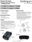
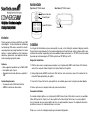
Hardware Guide
Top View (ST124W shown)
Rear View (ST124W shown)
Power Indicator
Video IN port
VGA Splitter / Distribution Amplifier
ST122W, ST124W, ST128W
Video OUT ports
Power Port
Introduction
Thank you for purchasing a StarTech.com VGA
Video Splitter. An ideal solution for distributing
and delivering VGA source content for simultaneous display on up to eight monitors, this video
splitter is a perfect addition to retail, tradeshow,
education, government and corporate environments requiring high quality video.
Features
• Max. supported resolutions up to 1600 x1200
• Cascadable up to 3 levels
• Supports transmission distances up to 65m /
200’
System Requirements
• A computer with a VGA Card installed
• HDB15 male/female video cables
Installation
In a Single Unit Installation, only one video splitter is used, in turn limiting the number of displays to which
the split signal can be broadcast; a Cascaded configuration on the other hand, utilizes multiple splitters connected to one another to providing numerous additional video connections (i.e. ST122W can be cascaded
to provide up to 8 video outputs, ST124W up to 64 and ST128W up to 512.
Single Unit Installation
1. With the video source computer powered down, use a high density HDB15 male/female VGA cable to
connect the computer Video Out port to the Video IN port on the splitter.
2. Using a high density HDB15 male/female VGA cable for each connection, connect the monitors to the
Video OUT ports provided by the splitter.
3. Connect the Power Port on the video splitter to an available power outlet, using the provided adapter.
4. Power up the source computer and newly connected monitors.
Cascaded Installation
To cascade multiple splitters, use a high density HDB15 male/female VGA cable to connect any available
Video OUT port on the “higher level” video splitter to the Video IN port of the lower level video splitter.
You can cascade as many video splitters as there are ports available, however the signal will deteriorate
as distance between the monitor and source increases.
Please see reverse for a diagram depicting a cascaded configuration.
Cascaded Installation - cont’d
Support, Warranty Information, and Regulatory Compliance Statement
If you ever need help with your product, visit www.startech.com/support and access our
comprehensive selection of online tools, documentation, and downloads. This product is
backed by a one year warranty. In addition, StarTech.com warrants its products against
defects in materials and workmanship for the periods noted, following the initial date of purchase. During this period, the products may be returned for repair, or replacement with equivalent products at our discretion. The warranty covers parts and labor costs only. StarTech.com
does not warrant its products from defects or damages arising from misuse, abuse, alteration,
or normal wear and tear.
VGA Signal
Source
Limitation of Liability
In no event shall the liability of StarTech.com Ltd. and StarTech.com USA LLP (or
their officers, directors, employees or agents) for any damages (whether direct or
indirect, special, punitive, incidental, consequential, or otherwise), loss of profits,
loss of business, or any pecuniary loss, arising out of or related to the use of the
product exceed the actual price paid for the product. Some states do not allow the
exclusion or limitation of incidental or consequential damages. If such laws apply,
the limitations or exclusions contained in this statement may not apply to you.
Specifications
Function
Display Connections
Video In
Connectors
Video Out
ST122W
2
ST124W
4
1 x HDB15 Male
2 x HDB15 Female
4 x HDB15 Female
ST128W
8
8 x HDB15 Female
Power
LEDs
Power
Video Bandwidth
250MHz
200MHz
Resolution
1920 x 1440 @75Hz
1600 x 1200 @ 60Hz
1 x DC Jack
1
Signal Range
Power Consumption
Operating
Temperature
Storage
Environment
Temperature
Humidity
Physical
Properties
Weight
Dimensions
FCC Compliance Statement
This equipment has been tested and found to comply with the limits for a Class B
digital device, pursuant to part 15 of the FCC Rules. These limits are designed to
provide reasonable protection against harmful interference in a residential installation. This equipment generates, uses and can radiate radio frequency energy and, if
not installed and used in accordance with the instructions, may cause harmful interference to radio communications. However, there is no guarantee that interference
will not occur in a particular installation. If this equipment does cause harmful interference to radio or television reception, which can be determined by turning the
equipment off and on, the user is encouraged to try to correct the interference by
one or more of the following measures:
• Reorient or relocate the receiving antenna.
• Increase the separation between the equipment and receiver.
• Connect the equipment into an outlet on a circuit different from that to which the
receiver is connected.
• Consult the dealer or an experienced radio/TV technician for help.
Up to 65m (210’)
DC9V, 1.35W (Max.) DC9V, 2.25W (Max.)
DC9V, 2.5W (Max.)
0 - 50°C
-20°C - 60°C
0 - 80% RH, Non-condensing
0.14kg
0.15kg
11.45 x 8.75 x 3.33cm (L x W x H)
0.22kg
15.59 x 9.79 x 3.33cm
Rev: November 9, 2007