1
TOTAL ENGINEERING SERVICES TEAM, INC.
(TEST Inc.)
A Weatherford Enterra Company
SCADA WARE ™
ALLEN·BRADLEY
PLC PROTOCOL
INTERFACE
Document 1250-02
Revised; April 1996
Thi.. document is {Cl Copyright 1994 by
Total Engineering Services Team, IncorpQreltod,
(TEST Inc.), New Orleans, La, USA
All Rights Ros(}fVod
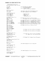
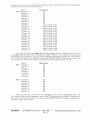
CONTENTS
INTRODUCTION . . . . . . . . . . .
1
PLC~5
HARDWARE INTERFACE
2
FULL vs HALF DUPLEX .....
2
MAP SETUP FILE KEYWORDS
3
MSG Text message " . , .... ,." .. ,' . . . . . ,
, ... , '
TAG
Tobie Rnfmence 10 . ,
, , , . , ,
ERROR Specify BCC or CHC Error Checking " . " . "
ACK
Control Message Acknowledflements " " " " " ' "
DUPLEX Specify Full or Half Duplex Protocol . , . , ' " . , "
STATION Specify Station 10 ,,' , . . . . . , , . , ,
UNITS Multi PLC Emulation , .. , , . , ' , , , .. , . , , . , , , ' ' .. ,
lD Set PLe Address .. ' . , , , ,
, .. , ... , .. , . . .
SELE Select Logical TSP RTU .. ,
.. , ... , . ,.
FILE Doline a pLe Mal) File . , .. , . '
, . ' , , . , , .. , , ,
MAP STATEMENT Deline map between lSI' and PLC data, , , ,
MAP STATEMENT OPTIONS " . . . . . . . , .... ,.,
:3
3
3
3
3
3
!J
4
4
4
b
5
SAMPLE PtC MAP SETUP FILE ...
7
SETTING UP A PLG PROTOCOL TASK
8
MAP SELECT xx ' , .. ' , , , , , ' , , . , , , , , ' .. , . ,
MAP LOAD xx AS Ifilename] , . , " " " " " " " ' "
MAP DUMP [filename] , , . ' , , . ,
. , . , , , .. ,
MAP SeAN stn:dst file starl count
, ' , .. , ' , . ' . , . ,
MAP DATA stn:dst file start count
. , , , , '
!l
.,
"9
9
10
.. 10
SAMPLE TSP DOWNLOAD FILE
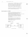
INTRODUCTION
A!lon~Brudley PLCs CUrl receive;! command mt:.1ssages and n~plv to them via Dal!;l Highway, Data
Highway Plus, DH485, or RS,232 network, By using the appropriate interlace modulo, a TEST SCAD A
system can access the network and communicate with any PLe using tho AlIen,Bradley protocol.
fhis document provides dotailed information on TEST's implemnntation of 1he") Allen"Bradley
cornrnunic1:11ions protocol. Althmlgh the user is not expeetod to be an expert, some farniliarir-y with
Allen-Bradley PLes and TEST SCADA systems is assumod. This docurmmt is nol Il tutorinl for
Allen~8radley PLCs. For additional intorrnation about A-,a PLC;; tiod intertacH fll0du!HS rolm to the
!ollowin;l A-B publications:
Publicfltion 17706.5,16
Data Highway/Data Highway PlllS/DH 4!l5
Comrnuniciltion Protocol and CO!l1!1l,md Set Reference
Manuar
Publication ICCG-ll.6
AlIGn Bradley Communication
SCADAApplications Guide
Dfvi!Jlon
Oma Hlgl-lway or Datn Highway Pit;:;; Asynchronous
(RS-232~C Of RS~422'A)
1770~I<F2)
Publicatioo17!l5~6.5,2
Irtorfact) Modulo (Cat. No,
User's Manunl
AlienBradloy
17851(E
Datn
Highway
Plus
Communications Interface Modulo User's Manual
April 1'lli6
Page J
PLC·5 HARDWARE INTERFACE
The TEST SCADA software tIses a standard RS232 port lar cornmUI1lC1l\lon. This port cfln b"
connected to an Allen·Br"dley PLC·5 in one of the followinu thren ways;
1
2
3
A 1784·CP1 0 or 1784·CP11 interconnect cable con be used for a direct connection to Chanll<,1
a PLC 5, This provides communication to a sioglo pte on a pOflr to peer basis. Euch
command received hy the PLC through channel 0 is processed without regard for the
Destination ID included in the command. Th!; Source 10 includnd in each command is aetilally
used to specily a file n"mbor in the PLC's memory for Wllich HIe command applies.
o on
A '} T70~KF2 modu!o can be used to connect to Chanm-rl 1A on a PLC·'5 and cornmuniciJte over
trlEl Data Hi~Jhway Network. When using this module, tho Source !D included in the command
is leplacfld with the address 01 the 177()oKF2 modul8 b8fon) being sent to tho intemlod ['LC.
Since the SourcfJ ID is nctually used to specify a file number In a PLC~:l nWnlory, only 3. sinole
lile can t)(; accessed for each PLC connected to the 1170·KI'2 module. This file is called a
"Compatibility File!" and its number is the St:lflil1 as thfi address of the KF2 modulo. The bit
modify and move instructions BTO, MOV and MVM can be used In a PlC's laddOl legic to
ItDn'fer bits to or from 1110 compatibility tile to other atHas of a PLC's memory.
A 1785··KE module can be used to connect to Channel 1A on a PLC··5 and con1murlieato ovur
tho D'Jtti HlghwflY Network. This modulo contains a dip switGh which can bo set for oHhnr
LOCAL or REMOTE mode. When in Local mode the 1785KE module functions just like IIHl
1770·KF2 module mentioned above. However, when in Remote mode the 1785·KE modulo will
:lOt roplJ;i(;H t!lt'S Source ID with its own address beforo sending the command to tho inltmded
PLe. It will Simply pass along whatever Source ID 'S inciuded inlhe command ]"SI as if 11 1784
interconnect cable were being used.
FULL vs HALF DUPLEX
Full duplex l!i used for point to point !inks where two devices cOllltnunicflte on a peor to peter
basis, This involves simultaneous two··way COffllTHmieations and both stotlons on the link can 'inItiatE)
commuoh::atlOns whenever they wis.h, Full Duplex CiJn Also he used to cornrnunjc~He to Ci numbcr of
r"rnote stations on the Data Hi9hway using point to point links.
Half d\lplex is used for multidrop networks whem tbere is one master statio1l il'1<J ope or more
slave stations, AJl Htahons arc tied together on d common link, tlfld 1hus everybody homs Everything
transmitted on tho link, Since there is pot(~ntjiil for two station's transmissions 10 collide it they both
try to transmit at once, only the master ean initiate (j message any time it wishHS. The :{!aves CHli only
cormmmicBte when pollod by the master.
V:or comrnunication:; betweHn a number or stations, oither Full duplex or Half dl!plex Gou!d bH
used. Using Full duplex will provide n,C best perlorrnance. However, it is moro expensive siuce
r.ornmuniclllions 10 tile remotes are via dedicated porn! to pOint links. Half duplex is bllsed on tull·dupiex
protocol but also includes a Station 10 at the boginning of 03ch mastm moss'19<J.
WhHrI the TEST SCADA softwmo is actinn as i":1 master using half duph-:x protocol, tl1(:1 Station
ID included in l13Cll outgoing nleSSa\J8 is provided by tile MAP SCAN or MAP DATA command. The
station ID reprosents tho Address of a slavH on a multidrop link. This should not ho confused with tho
Dosttnation 10 which is the final destination of the nH;ssage.
In mOot situations. a PlC is actually a SI,lVC, on the multidrop link and the final destination of
;;1 nmssagH, Therefore, the SRC nnd DBT are the smne, However, when multiple PlCs fJ~C timi into .a
network interfaGB module, the interfaCf; module acts flS (j f>lave on lhe multidrop link .and the PLCs are
Ill" ullin1atc destinations 01 the mossi;lges. In tliis ,.iluation, tho MAP SCAN and MAP DATA cornnlz1l1ds
should sptlGily the StnHon ID to btl the address of tlHl intertace module and i!lB DHstinfltion I[) 10 be tho
address 01 tho intended PLC. Refer to the MAP SCAN command for more information on how 10 specily
a Station 10.
SCADAWARP"
A7IenIJradley Pl.C Protocol
April 199(,
Page 2
Total Ellginel'l'illg SerVlcr's Team
1'1'S'['
MAP SETUP FILE KEYWORDS
The map fiie contains [>Iam text statements on lines which benin with Map Fila keyword,,, Each
line performs a specific function to build and define the tables which form tlw data map between TEST
SCADA data types and Allen~Bradley PLC data types, The map file can be proc(,sHed by mw task,
although normal practice is to have it processed by Task 0 during systmn startup,
The format of the file is very similar to other TSP t()Ht files, The keyword is tb" first word on
the line, and some aoi)«wiations are allowed. A semicolon (;l can be used 85 a comment C:laracter,
allowing tor comments anywhere in the text file.
MSG Text message
T oxt meSSiJges can ue !:::ient to the systf.lrn comwle during mop tile '" '.'Lt,"
statement. AI! text atter the MSG keyword \s echoed to tht~ Bystem console.
TAG
with tho MSG
Table Reference ID
Set H1e tag name for the data map being defined. By defaUlt. the t3g names for e3Gh (lata map
are MAP'!, MAP2, MAP3, dfld so on, These tag names Call be llsed by any RTU type task to select a
datA map by tag name rather than by Inciex number,
; Tag for this table
IS
PLC'I
ERROR Specify BCC or CRC Error Checking
Specify lhe type of error checking that will be used to check the accuracy of eaGll rnp.ssage
packet transmission, Tho two types of error chocking available are the block check character (BCC) and
the 16,bll cyclic rcdundancy check (CRC~ 16), The keywords BCC and cr,c alf) used to specify the type
of error checking 10 use, The default is BCC,
Error CRC
ACI{
; Specify CRe error checkrnu
Control Message Acknowledgements
Specify ON. OFF, or AUTO to control message aCKnowledgements to
t1
Ple. Spec.fvin[l ON will
Gause an ACK 10 be sent to H PLC after !loch message is successfully reCeIV{0(i, Specifyino AUTO will
cause an ACI< to be sent to (l PlC beforH B(lCh nlHSsagl11s sBnt and after ouch rnossage is sU(;(:nssfully
recoived, The default setting is OFF which prohibits any ACl<" from beillg sent nnd can significantly
reduce the number of IleGessary transmissions,
; scn(i ACK after (:wGh rne!:Hmgn is successfully received
; send ACK bH'fore sending rnsu and after receiving msg
ACl< ON
ACl< AUTO
DUPLEX
Specify Full
Of
Half Duplex Protocol
Specify whether FULL or HALF duplex p,otocol will be
For more information refer to s"etion Full VB Half Dllp1t0X,
DUPLEX HALF
USot),
Tho default sotting is Full Duplex,
; use Hall duplex protocol
STATION Specify Station 10
SpcGify the St£ltion ID for th(·1 current map t(1hlc. ThIS 10 is only nocessary when
USIn!:1
half
duplex protocol. In half duplex, the beginnill\J of each message sent by a master contains a St;;[ioll ID,
Whon this unit is acting as a SloVH and a mossage if;: received. a check is dono to seo that the Station
SC/;7Jl(WARE""
Api'll 1996
Page :1
towl EIIllil1<'erillg Services team
~
ID included in the l1lossBye tnatcbes tho Station ID of this unt:'. It It dOBt) not
n~atcl)
the message is
i{:]noroo.
NOTE: TI1is Station ID is only used to check incoming mBssages, it is not included in any
rC<lpOn3e to incoming messages or in outgoing m8ssolJcs initiated by this unit acting as a master. When
[lctinn as a master, the StatlOll ID included in any ou1going
1ll0ssa~J(J
is providod by tho
MA!'~
SCAN or
MAP DATA command ;\selt.
; specify S1 N llddress of this map
STATION 8
UNITS Multi PLC Emulation
Within each data map, up to 16 PLC IDs can be defined, each wl!h its own rnap setup. Tho
UNITS cO'Ylmand defines how many logical Allen BrDdloy PlCs will be ernulal'J(j by the data nwp beinfj
defined. If this command is omitted, ij value of 0 is assumed_
; allow 5 different PlC addresses to bo emulated
Units 5
ID Set PLC Address
Specify the Pl.C ID number to be used for subsequent data maps ,1S woll as the maXllTlUlH
numhcr of lilos that can be mapped for that PLC_ No tublG sizes or data lnilpS can be defined umil ,m
10 has been specified. Valid IDs '<my!l from 0 to 254 and each 10 COllllJ1Blld will begin tho next map
setup. Data can be mapped for any PLC file slarting with 0 and ranging up to the maximum number of
f:los specifi(!d rninus- OO(L
ID 4 9
: start defining PLC address 4 with a maxi,null) of 9 flies iO-S)
SELE Select Logical TSP RTU
Solect a logical TSP HlU which is used ltl subsequent TSP data table references. Tilis is a
convenience so that subsoquent nlAp lines do not 11MB to explicitly name a particular HTU on each line,
Tht RTU named in tho SELECT line will be the deluult RTU.
Sele W034A
; map following ehans for West Dalta 34 A HTU
FILE Define a PLC Map File
Define u PlC file which is used to map specific PLC data types with TSP data types_ Pmamolers
include (1 file number, a keyword specifying the type of file and a nurnl",r specifying the number of
eiernonts in the file. Available file numbers ranne from 0 10 the maximum number of files specified in
rhe 10 statement minus one. rhere are only 4 PlC data types supported at this time and tite available
keywords me:
OUTPUT
. digital, off or On
INPUT
digital, off Or on
INTEGEH
16 bit integer
FLOAT 32 bit floaling point
If more than one file- definition exists tor the same fila nurnber under the SArno rnf;lp ID on!y the
lirst definition line for that Iii" will be accepted.
f
FILE 0 OUTPUT 256
riLE I INPUT 256
; defme file 0 as type Output with 256 elements
FILE 7 INTEGEI1128
FILE 8 FLOAT 64
; define file 7 as type Integer with 128 elmnents
; define file 8 as type cloat with 64 elements
; defitlH fife 1 as type Input with 256 elements
/lpril1996
Page 4
,t~juj) Engineering Services Team
'fe.')T
MAP STATEMENT Define map between TSP and PLC data
SI)HClfy II link between TSP cilannel data and PLC file data. Parameters include a pte fill'
nurnber, a number repr0~}{lntlf1g tnH position within that file, a TSP channel or ehannn\ range and
optional data type speciiication. The specified PLC file number must be defined USili~l the FILE
statement before it can be mapped.
Fuliowin" the PLC file number is a number which lepresents the position within that tile where
the TSP cllannol mapping will begin. Remember, data within a PLe file starts at pOSition 0 and nxtends
up to the maxirnlHn nurnber of Oi(!H1HlltS in the file minus 1.
Thu next panHnt~ter G(lf) be either a single TSP chtlnm;j or n Ghnnnel range. If £1 sinu!e channal
is [liven it is directiy mapped with the specified PLC file and position. If a channel rtmge is specified,
the -t-irst channel in the range is rnapped to the specifled PLC file and posltion. Consecutive channels
in the channel rml\lc are mapped to consecutive rositions in the "Blne PLC file.
For Gxan1ple/ conSider the following lines which could be LHiCd to mnp TSP Output channels '} (j
with PLe Output iile 0 positions 0-4. In this example e8ell line maps a sinola TSP Output channel.
MAP 0 0 01
NAP 0 1 02
MAP 0 2 03
. Map Pl.C file 0 position 0 with TSP channel 01
; Hap PLC file 0 position 1 With IS? channel 02
MAP 0 3 04
MAP 0 4 05
By using a channel (FInne, the $q1TH3 5 TSP Output channels could be mapped to tho S[inlH fi
Output file positions in If sin~jle comrnand as shown belOW:
I1AP 0 0 (J 1: 01)
; map chans 0105 with file 0 positlOns 0·4
Tho fOmsjning parametors of a mRp specification are strictly optionaL These parameters are
keywofds whieh specifY exactly what
files.
df!t~
pertaining to the TSP channels wii! be mapped
[0
tile PLC
MAP STATEMENT OPTIONS
For PLC Output <md Input flies, (loeh file location contains 0 i thm a 0 01' a
Th(~(f)toro,
nnch
location can be mapped with the value of n digital TSP cilanooi (Status Input or Output) Of the status
of a channel condition, such as tho eXlstHncB o'f a partiGull11' alarrn conditioll. The rwallahle keywords
for specifying which channel data wil! be mappod into each PLC Output and Input file location are listed
below. Following "ach hlyword is the condition for which the correspondinu PlC iocati')fi:; witi contain
o 1 when the data is transfmred from rsp.
VALUE
NEW
ALARM
If current value of channel < > 0
if in alarm but not yet acknowledged
DB
RES
if t:lfHlI'HU but 13tH! within deadhand
iI ackllowledged but stili in alarrn state:
ABNORMAL
it no longer in alarm nnd waiting for reset
if alarm conditions NEW, ALARM. or RESET exist
If no keyword is specified the keyword VALUE is assumed. For PlC Outputs and Inputs.
In!l!tiple koywordG Gan be spocified on a sing In linc. In fluch 8 case, the ass-Delated PLC file location
wouid cOlltain a 1 it any of tho conditions am lila! at the time of the transfer from TS? to the PLC. For
cxanlple, consider the followin\l 3 map setup lines where file 0 I~ a PLC Output file:
MAP 0 0 01 Value
MAP 0101 Now
MAP 0201 Value New
Now considm tile value of PlC Output locations O. 1, and 2 after an update of these 3 iDeations
frolll il TEST SCADA unit. if til" value of Output channell is I, PlC Output file 0 pOsihon 0 would
contain fl 1, otharvvi~B a 0, If Outptrl channel 1 is in alarm but has not yet been acknowlodged, PLC
SCAOAWAIIE'ffl
ATr;;;;:lJradley 1'1.C Protocol
April 1906
PaRe :;
Oulput file 0 postion 1 would contain" 1, otherwise a O. If either the value oj TSP Output channel is
1 or Output channel 'I is in alarm but has not yet been aekuDwledged, PLC Output file 0 postion 2
would contain a 'I, oUItlrwise n O.
An update 'from n TEST SCADA unit to a PLC can occur in 1 of 2 ways, First, i;1 roque-fit Gan Uf!
sent to a TEST lInit acting as a slave. Tho TEST unit would interpret the roquest, tl\Jild ur a response
in the PLC format, and sond bock the rOSpOm1(L SOGond, the TEST SCADA unit C[1!l act (l~ 1:1 master I:md
simply build up n PLC command and send it out.
Now let us consider what bappel1s when data is transferred in tho Opposite diructiol1, frorn a
PLC to a TEST SCADA unit, When data is transferred in this direction, only the PLC IDeations that are
rnapPl)d to TEST SCADA channel VALUES 11'1111 have an effect on the TEST SCADA unit. For example,
again consider the following 3 map setup lines where file 0 is a PLC Output file:
MAP () () 01 Value
MAP () 1 0'1 Now
MAP 0 2 0'1 Value New
Now consider tho state of tho TEST SCADA unit after an update from these 3 PLC loc8tions,
If the valu» of PlC Output frle 0 position 0 is 1, Output channell 1 would contain a 1, otherwise a 0,
The update from PLC Output file 0 position 1 would have no effect on the TEST SCADA Ul1lt because
value. Tho update trom PLC Output file 0 position 2 would
the mapping doos not contain"
ci,a,,,,,,1
have the samu {:ffm:t as the t~pdato from pte Output FBe 0 position 0" This is hecauso tho NEW
parameter would l)c ignofm! and tho VALUE pammeter would work the SiJmo as it did to! position O.
Tiler" itl one last point worth mentionin~ about the mapplI1g of PLC Output and Input files. 8mc"
these locinions cuntain either fl 0 or a 1, they are easily mapped with 1he Status Input and Output
chmmels of a TEST SCADA system, However, PLC Output and InlHlt files can illso be mapped to any
other type of H,ST SCADA channel. Transferring data for vain" typo Ghannels Is exactly the sarne as
transforrlng data for (11gitol typo chann<lls. When going from a TEST SCADA unIt to a PI.C, tho PLC
location will bf;) set to 1 when the value of the corresponding channel is not oqua! to 0, otherwise It W!1l
be sot to O. When noing from R PLC to R TEST SCADA lInit, a channel value will be set to 1 wholl tilO
PLC location contains a 'I 01 herWlsH it will be set to O.
t
For PLC Intoger files BHCh locatiun contains a 16 hit in1flUBf value, What eac!) 16 bit value
represents dopends on the man sc;tup for each location. ThH availabl0 koywords for ~;pecifvin~l what
dMa will be mapped into cad, PLC Input file location are listed below.
VALUE
HI
LO
DB
A
integer representation ot channel's current
hi alalP' selpoifll
10 almr" setpoint
dOt'1dband value
VElIUH
If no kHyword is specified th(~ keyword VALUE is assumed, It moro than one keyword is
specified only Ihe tltst ono will have affect. Consider the follOWing MAP setup lines whero file 7 is a
PLC Integer file:
MAP
MAP
MAP
MAP
I 0 VI
I 1 Vl HI
72 Vl LO
7 3 Al DB
<;"
map integer value of V 1 WI til file cl pos:tlon 0
< map integer format of hi setpoint with pas 1
< map Inteuer format of 10 setpoin! positron 2
<
map integ~r format dcadband with position 3
For PLC FJoating Point files each loe-ation contains a 32 bit floating point number, The data that
can be mapped to thesH locmions and the keywords used to sotup tim lllop an~ the sarne HS that for
Integer liler;, Now conSIder the following MAP setup lines wilere file 8 Is a PlC Floatil'l9 Paint file:
MAP80V'1
MAP 8 1 Vl HI
MAP 8 2 V1 to
MAP 83 A1 DB
<: - map float value of Vl with file 8 position 0
< map float format of hi setpoill1' with pos 1
< Inap float format of 10 serpaint position 2
<"
cnDp float format deodbund with position :3
ACiain, if no keyword Is spedfied the keyword VALUE is a"GumBeL
April 1996
Page (,
1/ltal Engineering 'services Team TEST
c
SAMPLE PLe MAP SETUP FILE
, Alhm·Bradley PFC T!lst File
Insg Allen-Bradley PL.C 11ap File Start
eRe
error
use 16 bit eRe error checking
ack OFF
duplex FULL
: do not send any Acks
use Full duplex protocol
units 3
, tota I of 3 pl.es to De si mnl ated
mS\J Starting Unit 1
ID 17
10
first unH is PI.C ID 17 with maximllITI 10 files
channel mappi n~l wi 11 be j'or 5S180 RTU
rsp
sele s5180
mS\1 Oef; ni ng PLe Fi 1es
0 output 200
file
file
file
file
output bi t fil e
mput bit file
1 input 32
71 nteger 10
8 float 16
integer' file
floating point fi
msg Mapping Output FiT e 0
lIlilp
a0
01
PLe Output 1'i1 e 0 bit 0 is val Ute of T5P OJ
: Pl.e Output fi Ie 0 bit 1 is nO\v alarm status of
Illap 0 1 01 NEW
TS?
map
map
map
mop
01
() 2 01 ALARH
0 3 01 DB
{) 4 01 RESET
0 5 01 ABNORMAL
Inap 0 6 01 NFl' ALARM
map 0 7 01 NEW RESFT
01
Itl
PLe Output file a bit 2 is in alarm status of TSI' OJ
PLe Output file (l bit 3is deadband status of TSP 01
: PLC Output fi leO bit 4 i $ reset status 01' TSP 01
: PLe Output file 0 tnt 5 is abnormal status of TSP 01
PLe Output file 0 bit 6 is New at' In alarm status of lSI' 01
: Ple Output ffie 0 bit f is new or reset status of TSI'
map Q 8 02
map 0 9 02 NEW
map 0 10 02 AI_AR~,
: PLC Output file 0 bit R is value of lSI' 02
map 0 11 02 DB
map {) 12 02 RESET
[flilP
0 13 02 ABNORMAL
map 0 14 S1:516
51-SI6
map 0 30 vI: v5
VI-V5
PLe Output file 0 bits 14-29 are rsp channel s
PIC Output file 0 bits 30-34 are '51' channels
msg Mapping Input Fne 1
map 1 0 51:s16
: PFe Input file 1 bits Q-15 are TSI' channels
msg Mapping Integer F'i Ie 7
map 7 0 a1:(110
: PLe Integer fi Ie 7 integers 0-9 are TSI' channpls
51S16 map 1 20 01:016
channe15 01-0]6
AI·AIO
!<IS\)
: PLC Input fi 1e 1 bits 20 3:, are lSI'
I-lapping Floot1ng P01nt File B
mao 8 0 vl: vB
map 8 8 al.:aB
Startlng Unit 2
5
,eIe 55222
IUS\)
ro-
TSP chllnnel mapping will be for SS222 RTlJ
IlIsg Defining PLe Files
fi Ie 1 input
Ion
msg fl."pPin. 9 Input File 1
map I 0 51: s16
msg Starting Unit 3
109
sele hi170
lSI' channel mapping w'lll be for HIl70 RIU
msg Defining pl.e 1.'11,,5
f11 e 0 output 100
file 1 input 20
SCADAWlIJlf'M ......·~4Iien-lff;'dlel' PLC PrO/oml
April 1996
Page 7
toral Ellgineering Services Team .. TEST
msg Mappl fig Output Fif e 0
map 0 0 01:08
msg Mapping Input File 1
map 1 n sl:516
msq Allen·llt'adley PLC Map File Done
SETTING UP A PLC PROTOCOL TASK
Sotting up a task to use tho
stops are:
Allol1~Bradloy
PLC protocol involves a simple 3 stop process, Those
1. Define the [ask
2. Load the map lilo
3. Select the data map
STEP 1. Any RTU type task, except task 0, can be used to communica!" using the A-B PLC
protocol. A singit, lin" in the main confi,)uration IDA Ti file is ali that is "r",derf to define un rnu lyre
taBk. Examples of such tines are:
TASK RTU Com I
TASK BTU AB-PLC
Tho keyword TASK indieatos a new task definition and the keyword RTU indicates the type of
task. The third item on the line can he up to 16 dwructurs lonfj and is simply the task name,
STEP 2. In order for the TEST SCADA system to rnterface with an A,B PLC, a tiie must be
pf(lcessed which "maps" TEST SCADA data types into A-8 PLC data typos. The details of what is
contqjnad in the map file are described elsewhere in this doc-umenL For nnw, we t'ls5Urne that the map
filB has already been cfOated and that it is correct.
The MAP LOAD command must be used to proeess the map file and stllnp the mapping sellenH),
rhis command call be processed by any FUU tyPfl task, including task 0, Norm.~lIy Ihis command is
processed by tlwk 0 during pro\lram startup. This can be either in tlte STARTO,RTU We or a subroutine
called from tillS file, Auaill, the details of the MAP LOAD command call be found elsewhere in this
document in 11 "'lOtion called MAP COMMAND,
STEP 3. Once 11 mappitlg scheme has I)e"n loadod it IS accf>sslbl.) hy any HTU typ" task,
However, the dafauit protocol for all RTU type tasks is tl,,'1 TSP protocol. In order for a task to access
11 data map llnd lise the Data Highway protocol the MAP SELECT command must be used. This
cQrnrnand is U$J.,,!u!!y procAssod frolll within the STAf,TxJiTLl me which automatically ~)ets processed
wh!.H1 the task is starled. Once a valid data rnap Is selected for an RTU typo task, tho protocol for lhm
!1lsk is determined by tile typo ot map selected. For mom details refer to the MAP SELECT command
in tho section called MAP COMMAND.
MAP COMMAND IN TSP LANGUAGE
This cnrnrnHnci is usod to load a map filo, solect a particular data mop for a task~ send dtttl:1 to
and receive data Irom another unit using the A-B protocol/ and list the c:ontinurntion of a dam mlJp to
a fIlu. The MAP comma[l(i can j10 proces.sed on!y by liTU type tasKs. Tho format oi' this G0111Hltmd is
the word MAP foliowed by a keyword and SOlllB additional parameters, The available keywords and an
explanation of each am givrm below.
MAP SELECT xx
Up to H) data mapping schemes can be defined on a TEST SCADA SyStHill at one tilTH",
Hownver. each task cun have aCcess to only Ofle dnta map at a timo. This command is used to select
[j pnrticular data map 101" an RTU type task. A data Inap can be selectod by Index nurnber or tag I1;;Hl1e.
mOAWARP M
,-,
Allen-Bradley pte Pr%r;;?
Ijpril1996
Page 8
T(,/al Eng/fwa! ngSei'i'/ceS Team tEST
Valid inciox nurntlefS raO!je horn 1 10 10 and tllo default tflg nucno of oneh map is tho keyword "TAG'
followed by lilA rntiex numbor, This lag name can be changed from within the map file dtlnng a map
load,
By detault, the current data map index for each task is 0, This rnaans lhal there IS no detall'!
data mapping scheme for any task and the default pr{)tacol tar nil RTU type tasks is the TSP protocol,
Once F1 valid data map is selected for an RTU type task, tl\o protocol tor that 1ask is deHtrmined by the
typo of map selected (Modbus or AB protocol),
The command MAP SELECT 0 can be used by 1m RTU typo task to disassociate itsolf with <lilY
datR map, This will cnuse the protocol used by that task to btl returnen 10 tlltl TSP protocol. If a thild
pararnntor is not specified in the command,
ij
nI8ss8})0
will be sont fo the task procHssing tho command
to show the current mop index for that losk,
MAP SELECT I
i
seleGl data map 1 for Gurront task
MAP LOAD xx AB [filename!
This command I:; usud to prOGHS!:.i a map file which defines a data map. In thiS command a valid
index number in the range 1 10 must be specified in placo of the xx shown above, Specifying n map
tag name lllstead of an index number will not work for this command. BeCHuse the data nwp to be
defined is specified in thi$ command by an index number, ti,e task processing the comrnand does not
havn to sHlnet this map, or any data map, prior to procHssinn this cornmand"
Following the map index number is the keyword AI:l which specifies thaI an Allen,Bradloy Illap
is boln!] dflfiliod. The last parameter on the line is optional Bnd is used to specify th(? n(lm~) of the map
file to be processed. If no file nam(l [s specitied, the default file name RTU.AB IS ';lgsurned, If D file name
[~~ specl~led but does not c;ootain an extension/ the default flle Hxlension AS is <'1!'};:;umed.
It nn attempt is made to process a MAP LOAD commancl using an index number tor which a
Ill(]P hus almady been dftfined , th() command will be
index number will
mOl 'lin
i~Jnor0d
and the current data
lTl(lP
fQr the specified
UnChBI1(Jetl,
MAP LOAD 1 A8 TEST
; process rnap tile TEST,AB to define mflp 1
MAP DUMP [filename]
This cornrnand is u::;ed to list 111e configuration of a dHtn map to a file. This command CiJn be
procossed by any RTU type ta$k, but two conditions must ilO mot I)[ior to processing ne cOf1llnand if
it is to be successful. First, the task processin~J the cornrnand must flave a valid rnap selected. Second,
the currently selected map must i)(l defined from a prior MAP LOAD cOlnrnanti,
The !flst pararneter on the lino Is optional and is used to specify the mmle of the fl!e to contain
the listing of the ",ap Gonfi~urati(]n, II 110 file name is specltied, the dcfDult file narrw AB,MAP is
assumed, If a file name is specIfied but docs nut Gontoin all extonsion, the dofilult file oxtenslon MAP
is ussurned.
MAP DUMP
; dump currently selectnd data Illap to tHo AB,MAP
MAP SCAN stn:dst file start count
This comrnand is used to request data "from a remote unit usinO th!:1 A· B prntoGOJ. This cornmand
can be processed by uny RTU type task except task O. Bofore processing this Gornrnand, the task
should ~lave a valid A·B datH lllap selected which has been do-lined using the MAP LOAD GOfTHnand,
The first paramoter on the line following the SCAN keyword specifies a DestlnatlDn ID and
possibly a Station ID, The Destination 10 represents the address oj tho PLC Ih<lt IS the; ultimate
destinatlon Df the message, This ID must be defined lor the currentiy selected data map at the time this
SCADAWARtM
Apri'l1996
Page 9
message is proGHssed,
Far all full duplex and most half duplex applications, the Destination 10 is all that rUlods to be
provided by this parameter. However. when lIsing half duplex protocol, this parameter call also include
a Station ID which is designated using a colon (:) and the format STN:DST. If lhe STN: IS not spt'cilied,
the Station 10 included in the outgeing message will bo the sarno as the Destination ID.
('allowing til" PLC ID is the file number for which data will be read from the PLL This file
number nl\Jst he defined for the spedfie-d PLC lD.
·r h(') last two parameters that must be specitied in tho SCAN cOIT'tmand are tho startrn[1loCHiioll
and nurnbc:r of !oct'ltions within the rnap for which data !s requestod, A!! rnnppinfj starts fit location 0,
For exmnpl<,. it a file of 200 elements is defined, tl", actual locations that exi,;! are 0, 199. If tho start
location specified is not Within the valid ranQo an error will result. If HHJ nurnbor of locations spedfied
extends beYfJrld the upper limit, the count will automat!cally bo reducod to eliminate the overrun.
When ~ TSP MAP SCAN command is processed an A·S Unprotected Read eommand iB
genernted. This command can generally be executed by any PLC node and is used to ,ead words of
data from .my arca of the PLC data table memory. The number of words to read is alftolp.atlcally
ealculntod based I.1n the type of data contained in thn SIJHcifif1d file. the stari'ng location in the Hlo ilild
tl1(;1 numhor of locations to reDd,
I'ull Duplex Modn
MAP SCAN 4 1 0 8
MAP SCAN 2 I 6 :l
; read 8 elClrnfmts starling {It location 0 frorn file 1 or PLC 4
; read 3 elements starling at location 6 from file 7 of PlC 2
Half Duplnx Mode
MAP SCAN 4 1 0 B
MAP SCAN 2 7 6 3
MAP SCAN 5:2 7 63
; read 8 elemonts starting at IDeation 0 from file 1 of PLC 4 Stillion 4
; road 3 elements starting at location G from me 7 of PLC :> Slation 2
; read 3 "Iern",-,t>; starting at loentian 6 from file'] 0 f PLC 2 Station 5
MAP DATA stn:dst file start COllnt
This command is used to sHnd data to
8
remoto unit using the A-B protocol. Tho paramoters
reqllirtKt by this conlrnand are the same "s thasH required by the MAP SCAN cO'llmand with tho
exception that data wiil be written to the specified file rathor thun read.
Whfm a TSP MAP DATA command is processed either an A B Unprotected Bit Write or fin
UnprotHc1ed Write comrnand is generated, The rcsultiny comrnand is determined by the type of fde
spocifiod ill tila command, If the spocified fite is 'lithO[ an Output or Input file an Unprotected Bit Wnto
cornrnand is gOItOfDtod. Otherwise, an Unprotectod Write cornrnand is generatod"
Full Duplex Mode
MAP DATA 4 1 0 8
MAP DATA 2 7 6 3
; write 8 elements starting at location 0 to We 1 of ptC 4
; write 3 elements sterting ilt location 6 to file 7 of pLC 2
Hulf Duplex Mode
MAP DATA 41 08
MAP DATA /. 7 6 3
MAP DATA 5:2 -, 6 :3
; writB 8 elernHnts starting at !ocation 0 to fUn "l of PLC 4 Station 4
; writH 3 t31elTHJIlts startil)O ilt iocatlOn G to file "7 of PLC 2. Station 2.
; write 3 alornonts startin~l at location 6 to tile 7 of pLe 2 Station El
SAMPLE TSP DOWNLOAD FILE
Assume thn! there are 2 AII(m~Bradley pLC data maps defined, The first datil map. MAP1, is
used tn communicato directly with :3 PLC slaves. Tho addesses of these pLCs will tle 1, 2 nnd 3 for
simplicity. The s()cond dHla map, MAP2, IS used to eornmunicnte with 2 additional PLCs that me
co",,,,,.:tmf to a 1 T10-KI'2 module. The addresses of these PLCs will be 4 and 5 ilnd the (lddress of the
1770-KF2 l11odl>ul0 will be 10, Both ciata maps use the 11illf duplHx protocol. Althounh all !.l PLCa eouid
have boon defined 1ll (i !'jingle data map, they oro setup in 2 dnta maps for Illustrntiv() purposes.
ApriTf996
faxe to
Now assume that task 1 will bo used as the A~8 PLC hlSk and tho fi!o LINK 1.HTU will be used
to tJet H continuous update from all 5 PLCs, Polling can automatically begin whennvor tfiSK 'I IS started
by includino the line READ LINK 1 in the STARTl ,RTU fHo, Following is an Hxample of what this
LINK I ,RTU filo would look like:
; Allen·Bradley PLe Constant Poll File
map se 1 Inap1
; 581 e fi rst dutu map
; scan 16 elements sturtlng at 0 from file 0 of PLC 1
scan 16 e'lements startlng at 0 from flle 0 of PLC 2
scan 16 elements starting at 0 from fi:e 1 of PLe 2
scan 16 elements starting at 15 from file 1 of PLC 2
scan 8 elements starti ng at 0 from fil e 7 of PLe :\
scan 8 elements starti ng at 8 from fil e 8 of PlC j
rrtdD scan 1 0 0 11;
llIap scan 2 0 0 16
map scan;> 1 0 16
map scan 2 1 15 16
map scan 3 7 0 B
map scan 3 8 !l 8
: sole socond data map
10:4 0 0 16 ; scan 16 elements starting at 0 from file 10 of Pl.C 4
10:4 I 16 a ; scan 8 elements starting at 16 f!'om file 10 of PlC 4
10: 5 7 0 8 ; scan B 01 oments starti ng at 0 from 1'11 e 10 of PlC 5
10: 5 8 8 B
scan B e'l emorrts starting at 8 from file 10 of PLC 5
map sol rnup2
map
map
map
map
scan
scan
scan
scan
if @ack(O) <> 0
; if 'last scan command was unsuccessful
fi 1e and constant poll
enair
I'etllrn
,quit processing
map data IO:s 9 24 8
send 8 elements starting at 24 to file 10 of PI.C 5
fOl'cP 1 read 1 inkl
queue up IIlsg to continue
constant poll
Notice thai the MAP SCAN and MAP DATA commands for MAP2 use the STN:DST notation
whore STN foprf,:.'Sents tho 1 }70~KF2 address ;::md DST represonts tho PLC addn.HtfL Whonuver data is
roquasted fronl F'LC 4 or PLC 5 It IS read from tl'" PLC's compatibility filo. Tho compatibility file of each
PL.C is filonurnlfl" 10 which matches the address of tile 1770-KF2 nH.lduio, Similarly, wlronever data
is sent to PLC 4 or PLe 5 it is written to the same compatibility file,
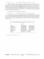
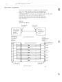
To better understand how to (lxchango data between a PLC usin\] a compf.ltibillty file and a
TEST SCADA syslHfn, lot's take a closer look at the two MAP SCAN commands shown above for PLC
5. These comrnands are:
map scan 10::) IO 8
map scan HI:5 8 8 8
; sCan 8 elements startmg at 0 from file ]0 of I'LC 5
: SCdn 8 elements starti ng at 8 from fi 1e 10 of PIX 5
tlS$Lllle thai fiie ., is dofined AS an Integer file and file 8 is definod as 11 Floatino Point file witliin
PLC 5, Also aSSllme that the data containod in filos '7 and 8 is to be mOPPo(j with TSP cl1annols as
shown below:
FUn 7
0
Elomant 1
Element 2
Eloment 3
File 8
TSP Channei
Vl
V2
V3
V4
Element
Elemont
Element
Elemont
4
5
6
7
V5
Element
Eloment
Elmnont
,'lemont
EI'Jlnent
Element
Elemont
Element
Q
1
2
3
4
5
6
A1
A2
A3
A4
A5
A6
A7
7
AS
V6
V7
VB
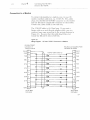
Now assume ti'lai' compatibility file lOis defined as all Intega'file within PLC b and the PLC is
SCAO'AJf11ilil'flir
7f1t('/lBmd1e.V
P['C I'm/owl
April f996
Page f I
pf'ngrHmrnod to continuous IV copy the first 8 elements of files 7 nnd 8 into this flit;. The mappod data
contained in file 10 minlrt til en look like tbis:
PlI:;§
File 10 Element 0
Element 1
Element 2
Elernonl 3
Elernunt 4
Element 5
Element G
Elernont
Element
Elemont
Element
Element
Element
7
8
9
10
11
12
Element l:i
Elermlnt 14
Element 15
EI()tllent
Elemont
Elemont
Element
Element
Element
EIHlTlont
Elemon!
16
17
18
19
20
21
22
23
I§t:J~tlJ,mlJQ]
VI
V2
V3
V4
V5
V6
V7
V8
upper 2
lower 2
upp"r 2
lower 2
upper 2
lower 2
upper 2
10 wer 2
upper 2
lower 2
upper 2
lower 2
upper 2
lower 2
upper:>'
lower 2
bytes of A 1
bytes of A 1
bytes of A2
bytes of A2
bytes of A3
by les of A:i
bytes of A4
bytes of A4
IJytes oj A5
bytes of A5
bytos of A6
bytos 01 A6
bytes of A 7
bytes of A l
bytes of A8
bytes of A8
a
Elie 7 and fill) 1 () ,lrO bolh Integer files Ilnd "aeil element takes up 2 bytes in eithm file. File
is a Floating Point file which requires 4 byms per element. TtH""foro. OIlC!l element in file 8 takes up
1he cqlJivalent ot 2 elements in fIle 10, In mdt1f to properly road all data mapPt"'!d with TSP channels
V1N8 and A'J·A8 from lila compatibility file using Il1e two MAP SCAN commands shown above. the
fEST system data mal) for pte 10 5 must be defmed as shown below lor files 7 and 8:
TSP.J":llannel
File 7
()
Element
Element
Elt--l!rHmt
Element
1
2
3
4-
EItH'1l (.)11 t [)
Elemell! (j
Element 7
File 8
EIt1ment
Eloment
Elormmt
Elermmr
Element
Ei<m1<ln t
Element
Elclne,,!
8
9
10
11
12
13
14
1b
V1
V2
V:,
V4
V5
V6
V7
V8
A1
A2
A3
A4-
At>
A6
A7
AS
Again, as wi til PlC 5. define file 7 as an Integer file and lilo <; as a floating Point tile in the
TEST systerrL Notice that the elements in file 8 of the TEST system start at position 8 ratller than O.
The reason lor this should he clear after examining the two MAP SCAN commands in more detail. First
of ull, let's look at Lho cOlnrnnnd
April 1996
Page 12
rotall~ngil1eering S(;;::;rc;;;·· ream
TEST
map scan 1,0:5 I (] 8
. scan
a elements
starting at 0 from hle 10 of PLC 5
When the TEST SCADA system processes tills command It first looks at the specified number
oj clements ond the type of dota contained in tho specified tile. To{]ethcr, this Information will
determine how many bytes the TEST system will attempt to read from Ihe PLC. In this command, the
specihocl iii" Is 7 which Is defined as an Integer fllo. Since there are 2 bytes per element and tho
number of elements specified Is
the TEST system will sen,l nut il cotml1llnd requesting 16 bytos from
the PLC. The data will be read from the com[Jatlbility file, file 10, starting with element 0 as specified
In the comnland, The returned datA wHI he writtt;ln to file l i0 thH TEST data map, o!Jnln stan:!n~J vvitl-!
olomen! 0 as specified In thH command.
a,
Now let's look ot tho second MAP SCAN command
map scan 10:5 8 8 8
; scan 8 e'lements start'ing at 8 from file 10 of PLC 5
The SpeC!fH0:d 111B in this Gomrnand is file 8 which is defined as a Floating Point file. Since there
are 4 bytf)s par olernont HOO the command roqu8sts 8 Blornonts from the PLC, the TEST systern wHl
send (lut a command requesting 32 bytes from !tIC PLC. Allain, the datil willI", read from compatibilitv
file 10. However, II\stead 01 starting with element 0, data will he read startin() with elernent 8 ;,s
specified In tho command. Tlw retumod 32 bytes will be written to fIIH 8 in the TEST data map sInrtlng
with posillon 8.
TOTAL ENGINEERING SERVICES TEAM, INC.TEST INC.
TEST INC.
tAAlt:LW1MBER
FAX NVMBER
1504) 371-3000
(504) 3713001
1318) 269·0911
(318) 269-0910
(713) 4673113
(713) 4678113
(805) 658-0403
1809) 658·9975
(907) 2.76-5660
(907) /76-5361
65-5334108 655342403
973690 575 973-697-010
OI'FIG.!;;
Now Orleans, LA
Lafavette, LA
Houston, TX
Ventura, CA
Anchorage, AK
Singapofn
Bahrflin
F;le: H1 ;'!!)O.WP
S/:ADAWARE'HI
AMl Pnntod Apd!
~j,
1996
Alle/l· BIYlflley pLC Pi-vioeol
Aptil 1996
Page 13
Towi Engineeiin,i(Servlces Y'eam .. 1t'!iT
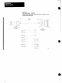
AppendlxB
Cable Connections
Figure B.9
Interconnect Cable - 1784·CPl 0
PLC·5/11, ·5/20, ·5/30, ·5/40, ·5/40L, ·5/60, ·5/60l, ·5/80 Processor to
Terminal (using serial port)
""' ............................................... 3.2m .........................
(10 fli
5
9SK1
IBM·AT Computel
25 pin
PLC Processor
Male
Female
BXD
2
2
GND
5
7
TXD
3
3
DCD
DTR
4
DSH
5
•
RTS
CTS
HTS
7
6
DSH
CTS
8
8
DCD
20
om
"
19870
"
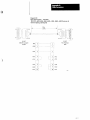
AppendixB
Cable Connections
Figure B.l0
Interconnect Cable 1784-CPll
PlC-SI11, -5/20, -5/30, -5/40, -S!40L, -5/60, -5IS0l, -5/80 Processor to
Terminal (using a serial port)
3.2J11
(to It)
25~SKT
25SKT
IBMXT Computer
Female
PLC Processor
Male
TXO
2
GND
7
flXD
,
RTS
-
2
4
5
RTS
CTS
osn
6
OeD
8
DSH
OCD
DTS
20
Olfl
US?t
13-17
3-12
C/),1ptCr
3
Installing Ih(l 1110KF2
If you al'!) connecting a 1770-KF'2 module lo an HS-2:l2-C
compatihle devi,,!; (e.g., modem or cOlnput.ec), thell you
must mount the til(Jdull~ within 50 cable feel of that
deVIce, For such appliccltions, tllc module's GNn fllll"t,
be connected to the (}ND uf the rnodenl Of COHlfJuter.
This type of connt:ei ion dnes riOt provide eteetricai
Isolatioll heLwet,,, tlie lllodule and the co!lIH,ded deVice,
If;;l
connection
i~
rnade between the; 1770-KF2 and an
RS-422iliA COH}p~,tible device. you cun rnount the device
and l-Iw I)wdlde up lo 40()O cable t(,el apart.
Direct Connection to a Computer
To connc(:t tIw rnod ule directly to Lt COll1puter ..you can
eOllt:;tntct. your own cable aceon::hng to the wiring
diagram in ligun, :.1,6a. This cable plugs into the
COMPUTI;;R ASYNCHRONOUS connector on the module and the
HS-2:32{; or H.S-422-A compalibl(s connector on the
computer Wgure :3.6a). Conned the cable shield at
'me end only. Be "ure that th" cable length does 110t
exceed the RS·2:32·C limit of 50 tect or the RS·422·/\
lun;t. of 4000 red.
This type of c"nIH'diun inc'ludes the DTH signal to
allow each end to deted the loss of the other end's
ability to communicate, If yonI' computer does not
provide the DTR signal, jump pins () and 8 at tbe
1770KF2 module t.o pm 20.
Figure ;1. 6;)
Connection 10
I'J
Computer
25~p!n
femalo
25~pin
connector
Asynctlrono(Js
port connector
of lT10·KF2
module
(RS-232·C)
/,
mille
connector
Cable
~
..-'I-------lt.".
a) Conn(!c-tofl Diagnun
RS-23l,·C or
RS·422·A
compatible
port
connector of
computer
l'igtJre 3.6b
Wiring Diagram for RS,232·C
Asynchronous.
Dort coYHlector
of 1710·KF2
mOdule
(flS·232·C)
f1S,232C
compatible pon
connector of
compu:er
-
,-.-
~2-
).,
.2.
Cab'e Inot exceeding 50 H)
~.
2
-3
I
yy
'v
,~
~
3
...2_
-
XI
~
~
2
~
P
~
b
~
~
s
Rxo
T xo
f--.
6
~
C hassis graund
20 L)TR
oeD
e::::::- '8
I-DSA
,.
XX
c
v
~
-i.
RT'S
r
...2..
CT~
./
25~pin female
connector
25--Din
ma!(~
co:,noctor
Figure 3.&.
WifJl'g Diagram for nS·422 A
A5ynchmnou~
port connector
RS,,422~A
of 1770·Ki'2
compatibie por:
connec:or of
computer
mOd,d(-J
(RS--.12:2-A)
Cahfe (not
(lXCUOdlIlD
4JOO HI
!lOA
RDB
TDB
Note
20
The connector and lile pin outs for
the HS·42:.!--A COfllf'i)hb!o cornputer
rot! will dtmeneJ on til(: computer
Illanutactufc:r' 5 standard assign"
fn()nt. Other f>I1S may have tn be
;umpGfcd on the computer connecter
to ens!1I e proper operation.
c) w:ring diagra:"fl for RS-422-A
ground
Chapter
Connection to
3
Installing the f 170~Kr2
Modem
if
To connect the module io a modem, you <:an construct
own cablf; according to the wiring diagrarn in
tigure :l.7. This cable plugs into tho COi\lPUTEH
ASYNCHRONOUS connector on the module Hnd the RS,2:l2·C
compatible eqnnector on the rnodern (n~iurB ;L 7).
CtHult!cl t1w cable shield at one end only, He sure
that the cable length does not exceed the RS,232·C
limit (If 50 fe.!L .
YOUT
Figure 3.1
Connection to a Mot1cm
25-pin [nalc
con-nector
2S~pin female
connector
Asyric.hronou$
port connector
of 1 nO·KF2
module
11S·2;12·C
compatlble port
COMnector of
rnodern
(RS·232·C)
Asynchronous
(a) Connection diagram
port COnMf1ctor
01 1770·Kr2
module
(R3·232·C)
1
"7
A
-
RS·232·C
compatible p<Jrt
connector of
modem
,0
XV
3
~
r:)
'XX
W
6
XX
a
'N
4
r-
-
1
Cable (not exceeding Sf) fl.)
T
'-'-
-
f20
"
female
connector
25~pir
TXD
3
RXD
4
RTS
-.
r5
r6
r-
CTS
DSR
g DeD
r-
Y:f
'-'
2
-
T
Chassis ground
Signa! ground
20 DTR
r25~pin I'nalo
connector
(b) Wiring diagram
141131
BliOE HOSE
1770~KF2
to PLC5
1.770 - 1<1"2
r-"
CLear
TOp
8
Shield
fil ic1
7
Blue
I10t
Connccting Your RS"232"C
Device 10 lI,c 1785-KE
Direct Connection to a Computer
To connect the module directly to a computer, you can
US!) a data terminalllltcrf~tce cable (cat. no.
I no-eG). This cabk plugs into the RS-2:l2-C PORT
connector on the module and tho HS-2:32-C eompclf.ible
COllncctOt' on the computer. Connect the cable shiold
at 011" end only.
The l770·CG cable i~ lfi.5 feet long. If you need a
l.(lnlSCr cable or a male/female adapLfll' cable. you can
construct your own accordulg to thp \vlriug dh:1granl in
Fil;ure 4.2. Make sure that the cable length docs not
exceed 50 feet.
fig/Jre 42
Wiring DmQri1l1l
FlS-232-C PORT Connector 10 Computer
RS-232-C PORT
connector of
1785-KE module
•
SHLfl
1
(iNfl
'1
7
GND
TXO
2 f--~"""1f----I-+--'''''''-''''---+--~ 3
RXD
RXD
:<
DSR
6
OCD
B
DTR
11
GND
13
4
5
RTS
CTS
1----------,
15-pin Male
Connector
,
1770·CG Cable (16.5 ft.)
RS·232-C compa!ible POnT
connector of computer
~
SHLD
8
6
DCD
DSR
GND
RTO;;
CTS
25·pin Male
Connector
Thus type of r;onnel'tioll indudes the DTH signal to
allow each end t.o detect the IfJ~s of the other tend's
~,biliL.Y to communicate. If you)' computer does not
provide th,) DTR sigl:al, jumper pins 6 and 8 ;11 the
moduli) tu pin II.
Cl1dpter
4
Cormecffng Your F'IS·232--C
Device to the 1785-KE
Connection to Another Communication Module
You tan wnnect the 178f)~Kl~ (,0 another Data Highway
interface module with a longline cable, This cable
can be up to 7,000 feello11g. However, nmwmher that.
the cable length can limit the C(llllmllllicafion "ak
(refer to the section carlier in this eh,~pU:1' entitled
I~l(,et.rical Cbaracter'Bties of the l~q·232,·C P(n't).
For inIi)nnalion on how to construct a longIine cable
fiJl' conm:cl.ion to a:
o
1771 ~KG module, refer to tIgllre 4.:3
!)
1773~KA
or 1775-KA module. refer to flgure 4.4
'1'0 const.ruct. tbe cable) use a Inale conrit·;ctor at each
nnd. UEe Belden Hna or equivalent. cable (available
from Allen-Bradley under <;at. no. 177fl"CH). CUllnecL
the cable shield at one end only.
4-7
Connecting Your RS~2J2" C
DevIce to the 1785 . KE
•
Fiouro 4.3
Connectioll to
{J
1771~KG
User-supplied Cable
Belden 8723
(7000 It. max)
RS-232-C PORT
connector of
17B5-KE module
15-pin Male
Connector
•
Mociule
RS-232-C
PORT connector
o11771~KG rnodule
(cal, no. 1778-CR)
I
Connect the shield
at one end only - \
15-pin Male
Connector
SHLO
1
TXO
2
3
TXORE1
14
~--~r-----~13
RXO
3
2
RXORET
13
RTS
4
CTS
5
Dsn
6
DCD
DTR
-
-
-
-
SIILO
-
'--r-+-+-------l
RXO
RXORET
TXO
14
T X 0 R E1
4
RTS
User-suppliecl Cable
5
CTS
Belden 8723
(7000 It. max)
6
OSR
8
8
OCO
11
11
OTR
L
User supplied male connectors - - - - -
Figure 4.4
Connection 10 a IT/3M or 17T5KA Modulo
User-supplied Cable
Belden 8723
(7000 1t. max)
RS-232-C PORT
connector of
1785-KE modul()
15-pin Male
Conneclor
r
Connect lMe shield
at one end only
RS-232-C PORT
connector of
1773-KA or 1775-KA
module
25~pin
MaJe
~ ~onnector
SHLD
SHLD
TXD
2
3
RXO
TXORET
14
25
RXORE1
RXD
3
2
TXO
RXDRET
13
7
TXDRET
RTS
4
4
RTS
CTS
5
5
CTS
DSR
6
6
OSR
DCD
8
8
DCD
OTR
11
20
OTR
L
User'~supplied
Cable
Beldon 8723
(7000 f1. max)
User supplied male connectors _ _ _
J
GOl1flec(illQ Your
Ghdll!er4
DDvice to
tho
RS,·232-,G
17{j5~J<E
Connection to a Modem
To cunnect llH; rnodule to a rnndcru you can use the
JflOd(ln1 llltel'faee cuble (cut, no, 177(H;P). This cable
plugs into the RS~2:32~C PORT conued.Of on the rnodule
and chI) RS·2:l2·C co.npatible connedlll on the lllodmll.
Conned the cable shield at (lnt, And unly.
J
The I 770·CP eable is 16.5 ["et long. If yon need a
longer cubit, or tl male/female: adapter cablr;, you can
l:Otlbtruct your own according to the wiring diagraln in
Figure 4.G. Be "un) that the cable lengtb do,'s noL
exceed ti1e I{S·2;l~~C limit of 50 teet.
Ngum 4.5
Wiring Diagrum ' RS-232- C ['OHl Councctor to 11
RS·232·C PORT
connector of
1785,I<E module
SHLO
Gt-D
TXD
RXD
"1
r:r
-'-
-
RS,232 .. C commpa(ible PORT
COf1nector of modern
r:-
)"
2
v
AX
r--
"'IX
4
r--'
CTS
Yj,
5
r-DSR
"
r--
OCD
8
~.
-xx
r-11
'XX
9
XX
(iND
1 770·CP Cable (15.5 ft.)
)(y
3
IHS
-.2iL
Male
Connector
15~[Jjn
MO(i(~m
'--'
r.2.
r2-
eND
2
TXD
I'-;]
RXD
~
I'-4
RTS
5
CTS
6
DSfl
8
oeD
-
-
-20
-22
DTfl
11 GND
-
2S~pin
Maie
COnrH;C!Or