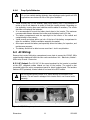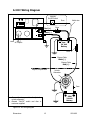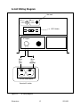
1
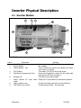
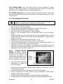
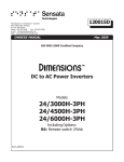
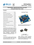
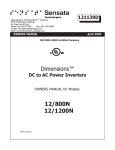
Form: 122142B
January 2007
4467 White Bear Parkway
St. Paul, MN 55110
800-553-6418
ISO 9001:2008 Registered Company
Dimensions
DC to AC Power Inverter System
Owners Manual for Models:
MIL-24U10AN
Dimensions
1
122142B
Table of Contents:
Section
Description
Page
1
Safety Instructions ..…………………………………………………..…
1.1
Warning and Danger Symbols ……..……..…………….…….…..
1.2
Inverterr System Precautions ………………………………….………
1.3
Battery Precautions …………………….……..………………...……
Specifications ……..……………………..…...……………………..……
Technical description …..……………………………………………..…
3.1
Power Inverter Systems …….……….…………………...……....…
3.1.1 Overview …………………………………….……………….….
3.1.2 Theory of Operation ….………….………………………….
3.2
Available Options and Features ………………………………….….
3.2.1 GFCI Protected AC Output – “A” Option .………..….
3.2.2 Remote “On/Off” Swtich ………………………………………
Inverter Physical Description ..……….……………………………….
4.1
Inverter Module ………….…………………..………...……………….
4.1.1 LED Control Panel Description ……………………………….
4.2
NATO Connector Plug – Optional …………………………………….
Installation ..………………………….……………………………………
5.1
Tools Needed for Installation ..…………………………….……….
5.2
System Components ..………………………………….……………...
5.3
Mounting the Inverter ….………………………………………………
5.3.1 Chassis Bonding Lug .……………………………………..…
Inverter Wiring …………..……….…………………………..………….
6.1
DC Wiring …………………………………………………………….…….
6.1.1 Inverter Cable .…………………….…………………………..
6.1.2 Charge Cable ..……………………….……..……………..….
6.1.3 NATO Connector …………………………………………………
6.1.4 Connecting the DC Wires ………..…………………..…….
6.1.5 Remote “On/Off” Switch ……………………………………
6.1.6 Deep Cycle Batteries .…………………………………..……
6.2
AC Wiring …………………………………………….…………….…..….
6.2.1 AC Output …..…………………………….…………………….
6.3
DC Wiring Diagram ..……………………………………………………
6.4
AC Wiring Diagram ….………………………….………………………
Operation and Troubleshooting ..………………………………....….
7.1
Operation …..………………………………………………………………
7.1.1 Turning the Inverter On ………….…………..…..…..…..
7.2
Troubleshooting ……………..………………..………………..….…..
Warranty ………………………………………..…………………….……
3
3
3
3
4
5
5
5
5
5
5
5
6
6
7
7
8
8
8
8
8
9
9
9
10
10
10
10
11
12
12
12
13
14
14
14
14
15
2
3
4
5
6
7
8
Dimensions
2
122142B
Safety Instructions
Important: Read this manual before installation, it contains important safety,
installation, and operating instructions. Save this manual and keep it in a safe place.
1.1 Warning and Danger Symbols:
To reduce the risk of electrical shock and to ensure the safe operation of your
Dimensions power inverter, the following symbols are used throughout the manual.
DANGER:
ATTENTION:
Important operating instructions.
Follow them closely.
Risk of personal harm and/or
electrocution exists in this area.
Use extreme caution.
SAFETY CERTIFICATION:
This is a UL and CUL Certified product that complies with all the safety
standards required in the USA and Canada for land vehicle inverters.
1.2 Inverter System Precautions:
•
•
•
•
•
•
•
•
DC to AC inverters produces hazardous voltages. To avoid risk of harm or fire, the
unit must be properly installed.
There are no user serviceable parts inside, do not remove the cover.
The inverter Systems should not be mounted in a location that may be exposed to
rain or spray.
The inverter Systems should not be installed in a zero clearance enclosure.
Damage to the inverter Systems will occur if correct polarity is not observed when
installing the DC input cables.
Damage to the inverter Systems will occur if an external AC power source is applied
to the inverter’s AC hardwire output.
The inverter System contains a circuit breaker and capacitor that may produce a
spark. Do not mount in a confined battery or gas compartment.
Be sure the inverter Systems is turned OFF during installation.
1.3 Battery Precautions:
•
•
•
•
•
•
Working in the vicinity of lead-acid batteries is dangerous. There is a risk of acid
exposure.
Batteries generate explosive gases during operation.
There is risk of high current discharge from shorting a battery that can cause fire
and explosion. Use insulated tools during installation.
Remove all rings, watches, jewelry or other conductive items before working near
the batteries.
Inspect the batteries once a year for cracks, leaks or swelling.
Dispose of the batteries according to local regulations. Do not incinerate batteries;
risk of explosion exists.
Dimensions
3
122142B
Specifications
MIL-24U10AN
Millennium Series Power Inverters
Output Voltage (VAC)
Output Frequency:
Output Waveform:
Input Voltage: (VDC)
Operating Temperature:
Efficiency:
120 ±5%
60 Hz ± 0.05%
Pure sine wave, < 5% THD
22 to 30
-20° to 40° C (0° to 104° F)
Up to 88%
Environmentally Friendly,
Quiet, Reliable, AC Power
Unit Protection:
Other Design Features:
•
•
•
•
•
•
•
•
•
•
•
Patented construction and cooling methods
16 bit, 5 MHz DSP (Digital System Processor) control
Thermally-controlled cooling fan
Enclosed AC and DC cable connections with strain
relief
Remote ON/OFF switch hookup
GFCI outlet and hardwire output protected
LED for Inverter power, Low battery, High
temperature, & Overload
Water resistant cover
Fully coated circuit board
Optional NATO slave plug connector with cable
Built to UL 458 standards
MODEL NUMBER
•
•
•
Automatic electronic short
circuit/overload protection
Automatic high temperature
shutdown
Output circuit breakers
DC input reverse polarity protection
Battery Protection:
Automatic low battery shutdown at 21
VDC (with in-rush delay)
Usage:
Any 120 VAC, 60 Hz single-phase
products within the inverter power
rating.
MIL-24U10AN
National Stock Number
6130-01-495-0740
Output Power (Watts Cont.)
Output Current (Amps AC)
Peak Output (Amps AC)
1,000
Up to 8.3
25
Output Rating: (hp)
¼
Up to 50
Input Current (Amps DC)
Weight (lbs.)
32
Dimensions in. (LxWxH)
Dimensions
•
15 x 11 x 6¾
4
122142B
Technical Description
3.1 Power Inverter System:
3.1.1 Overview: A DC to AC power inverter system converts DC current storage in
batteries to usable 120 VAC 60Hz power. The inverter have a main “On/Off” switch to
control the inverter operation, it also have LED indication lights built on the front of the
inverter to provide system status. The inverter can also be controlled by a customersupplied remote “On/Off” switch connected to the violet wire labeled “remote switch
hook-up” located in the field-wiring compartment.
3.1.2 Theory of Operation: The inverter converts DC power from batteries to
usable 120 VAC, 60 Hz power. The direct current (DC) that enters the inverter system is
filtered by a large input capacitor and switched “On” and “Off” by the Metal Oxide Silicon
Field Effect Transistors (MOSFET) at a rate of 60 cycles per second, and directed into
the transformer which steps the voltage up to 120 volts.
The inverter has a 16 bit, 5MHz Digital System Processor (DSP) to control the output
voltage and frequency as the DC input voltage and/or output load varies. The signal
output waveform shape is sinusoidal; it has a total harmonic distortion of less than 5%.
A thermally controlled cooling fan triggers when the temperature inside the electronics
circuitry reaches a preset temperature limit keeping the inverter within the operating
temperature range.
The water resistant cover and the fully coated circuit board protects the inverter’s
electronics from the elements, specially from moisture and water that may rust the
electronic board components.
The inverter cover has special venting openings that are not directly exposed to the
surround ambient, the venting openings are located from beneath on both sides of the
inverter to allow airflow circulation to cool down the inverter for efficient operation.
3.2 Available Options and Features
3.2.1 GFCI Protected AC Output – “A” Option: The inverter have one GFCI
protected AC output circuit with a 15A output breaker. With the “A” option, the 120VAC
60Hz AC outlets on front of the inverter and the set of hardwire leads are both GFCI
protected therefore it is not necessary to install remote GFCI protected outlets.
3.2.2 Remote “On/Off Switch: The inverter can be controlled by a customer
supplied remote “On/Off” switch connected to the 18-gauge violet wire labeled “remote
switch hook-up” which is located in the inverter’s field-wiring compartment, the line side
of the switch must be fused and connected to +24Volts.
Dimensions
5
122142B
Inverter Physical Description
4.1 Inverter Module
3
2
1
9
8
4
7
5
FIGURE 1:
Item #
1
2
3
4
5
6
7
8
9
6
Inverter module physical description
Description
“On/Off” Switch.
Branch Breaker
Output Breaker – 15A
Function
Switches the inverter ON or OFF
Not available
Trips to protect the inverter from hardwire AC output
short circuit or overload.
GFCI Outlets
Two outlets, 120 VAC 60 Hz out put power.
Field Wiring Compartment Cover
Remove the faceplate to access the AC output lead
wires and the DC input connectors.
Bonding Lug
Connects to the ground system.
Water resistant DC input strain Clamp the DC input cables for mechanical protection.
reliefs
Water resistant cover
Protects the inside electronics from the elements
LED Status Control Panel
Provides system status – See next page
Dimensions
6
122142B
4.1.1 LED Control Panel Description
1
2
3
4
5
FIGURE 2:
(1)
(2)
LED Front Control Panel
External power: Disabled – Not available with this inverter model.
Inverter power: The green LED indicates that the inverter is operating from
batteries in “inverter mode”.
Low battery: The red LED indicates that the inverter is in a low battery
voltage condition.
Overload: The red LED indicates that the inverter is in an overload condition.
High temp: The red LED indicates that the inverter has a high internal
temperature.
(3)
(4)
(5)
4.2 NATO Connector Plug - Optional
(1) Pin Connector: Plugs
to the female connector
for DC input power
(2) Black
Wire
(-):
Negative
DC
input
voltage from batteries
(3) Red Wire (+): Positive
DC input voltage from
batteries.
(4) Cover: Protects the plug
from dust when not
plugged.
4
1
3
2
Figure 3: NATO Plug – Optional item
Dimensions
7
122142B
Installation
5.1 Tools for Installation:
Tools required for installation: Straight screwdriver, connectors (butt type and
insulated), drill, Crimpers (for insulated and non-insulated connectors), electrical tape,
#2 Phillips screwdriver, wire cutters, wire strippers, cable ties, tape measure.
5.2 System Components:
Inverter
24U10AN
NATO
Connector
(Optional)
Figure 4: System components
5.3 Mounting the Inverter:
The inverter mounting location should provide adequate ventilation and
clearance to maintain room temperature during operation. At least 1/2 inch of
clearance is required on all sides.
•
9.0
Locate a suitable, secure vertical or
horizontal mounting surface as close to
the batteries as possible without being in
the same airtight compartment.
If mounting the inverter on a vertical
surface, it is recommended that the front
control panel be pointing down whenever
possible.
Locate the mounting holes on the chassis
flanges and fasten them using ¼ inch
diameter screws to secure the inverter.
See figure 5.
2.2
•
•
13.2
All dimensions are in inches
Figure 5: Inverter footprints
5.3.1 Chassis Bonding Lug: Connect the bonding
lug located at the right side of the inverter chassis to the
earth grounding system using an 8-gauge copper wire.
Figure 6: Inverter grounding
Dimensions
8
122142B
Inverter Wiring:
6.1 DC Wiring:
1
2
3
4
5
It is recommended in all cases to use stranded copper wires.
Use SGX cross-linked polyurethane insulation type that complies with the high
temperature insulation requirements (125°C.) of SAE J-1127 and vehicle
manufacturer requirements.
Wire gauge recommendations are minimum. For higher temperature rated,
applications inside engine spaces or large motor loads and other applications with
high surge currents use wire gauge 1 to 2 sizes larger than shown on table I.
Keep the wire runs between battery and SPS as short as possible.
Use Bussmann fuse type ANN-XXX and fuseblock # 3576 where XXX is the size of
the fuse.
6.1.1 Inverter Cable: This is the cable that runs from the inverter module to the
batteries. Estimate the “inverter cable” length and locate your inverter model on table I,
cross-reference the wire gauge and fuse size.
Table I: Wire and Fusing Guide for 24VDC systems at 5% Voltage Drop at Full Output
Inverter
Model
24U10
Full Load
(Amps DC)
50
Inverter to battery estimated cable length in feet
1’ – 10’
11’ – 15’
16’ – 20’
8-gauge, 100A fuse 6-gauge, 150A fuse 6-gauge, 150A fuse
Fuse holder Cover
Fuse
Cupnut
Stripped end
(To inverter DC input)
Red wire (+)
Screw
Terminal Ring 5/16”
18 inches
Red wire (+)
Terminal Ring 3/8”
(To Battery post)
Fuse
20 feet max.
Black wire (-)
Figure 7: Inverter cable assembly
Dimensions
9
122142B
6.1.2 Charge Cable: This is the cable that runs from the batteries to vehicle
alternator or OEM engine battery. Use 2-gauge cables and 250A fuse for small OEM
alternators and 1/0-gauge and 350A for heavy-duty alternators.
6.1.3 NATO Connector: If the inverter comes with a NATO connector option, plug
the pin male connector extending from the inverter to the female connector for 24-volt
DC input power.
6.1.4 Connecting the DC wires:
Damage to the inverter not covered under warranty will occur if correct
polarity is not observed when installing the DC input cables.
•
•
•
•
•
•
•
•
•
•
Refer to Figure 5A: DC wiring diagram.
Open the inverter field-wiring compartment to access the DC input lugs.
Unscrew the DC input lug POS (+) and NEG (-) screws.
Remove the fuse from the fuseholder for cable installation.
Remove 1 inch of insulation from the un-terminated ends of the red and black
cables.
Insert the stripped end of the red wire into the DC input lug labeled POS (+) and the
stripped end of the black wire into the DC input lug labeled NEG (-). Tighten the lug
screws to 10 Ft. Lbs.
Tighten the cover DC cable strain relief screws to 1 Ft. Lb.
Connect the end of the short red cable to a POS (+) battery post.
Connect the terminated end of the black cable (neg. return cable) directly to a
battery NEG (-) post (DO NOT connect to the chassis).
Install the in-line fuse in the fuseholder that is within 18” of the positive post of the
battery bank (a one-time spark will occur when this final DC connection is made). To
determine the fuse size, refer to section 6.1.1.
6.1.5
Remote “On/Off”
Switch: An optional customer
supplied “On/Off” switch may be
connected to the inverter. The
remote switch will operate only if
the main “On/Off” switch on the
face of the inverter is turned ON.
•
•
•
•
•
•
Open the inverter field-wiring
compartment to access the
DC input connector.
Remote
Switch
Hookup
Figure 8: Remote Switch Hookup
Locate the violet wire labeled “Remote Switch Hook-up” and remove it from the
positive battery connector.
Connect the violet wire to the load side of the “On/Off” remote switch.
Using an 18-gauge wire, connect a fused (5 amp recommended) +24VDC battery
voltage to the line side of the switch.
The fuse should be mounted within 18 inches of the battery’s positive post.
All material used for the remote switch should be UL listed and installed per code.
Dimensions
10
122142B
6.1.6
Deep Cycle Batteries:
Do not use vehicle-starting batteries; deep discharge cycles typical with SPS
applications can shorten the life of this type of batteries.
•
•
•
•
•
•
Install at least one 24 VDC auxiliary deep cycle battery (two 12-volt batteries in
series or four 6-volt batteries in series) to feed the inverter directly. Depending on
the application running time more batteries could be added if necessary. The vehicle
alternator will recharge the batteries.
It is recommended to mount the battery bank close to the inverter. The maximum
recommended distance between the inverter and the battery bank is 20 feet.
The battery compartment must be vapor-tight to the interior of the vehicle and
vented directly to the exterior.
Install several vent-plugs within one inch of the top of the battery compartment to
allow for ventilation. Install a ventilation assembly as needed.
Allow space around the battery and especially above the battery for inspection, and
maintenance purposes.
The battery should not be able to move more than 1 inch in any direction.
6.2 AC Wiring:
Remove the inverter field-wiring compartment cover plate to access the 120VAC, 60Hz
output hardwire leads and follow the color code connections: Hot - Black wire, Neutral White wire, Ground - Green wire.
6.2.1 AC Output: The 120 VAC, 60 Hz current produced by the inverter is provided
at the GFCI receptacle outlets located on front of the inverter. The output is also
presented behind the wiring compartment panel for direct hardwire leads. The hardwire
leads are GFCI protected; remote outlets do not need to be GFCI outlets.
Do not connect another source of AC power directly to the output of the
inverter. This will result in damage to the inverter that is not covered under
warranty.
AC Wiring compartment
DC wiring compartment
Figure 9: AC/DC Wiring compartment
Dimensions
11
122142B
6.3 DC Wiring Diagram
Remote
On/Off Switch
Fuse
Red (+)
Violet wire
Fuse
Black (-)
-
AC Output
+
Aux.
24 Volt
Battery
Fuse
Charge Cable
Black (-)
Charge Cable
Red (+)
Engine Compartment
Vehicle
Alternator
Fuse
•
•
OEM
24 Volt
Battery
Connect the charge cables directly to the
vehicle alternator.
Remote “On/Off” switch and fuse is
customer supplied.
Figure 10: DC wiring diagram
Dimensions
12
122142B
6.4 AC Wiring Diagram
Not used
Output
Breaker
15
Branch
Breaker
GFCI Outlets
AC Output
Black
Wire
Hot
White
Wire
Neutral
120VAC 60Hz Output
Remote AC outlets
Figure 11:
Dimensions
AC wiring diagram
13
122142B
Operation and Troubleshooting
7.1 Operation
7.1.1 Turning the Inverter “ON”: To turn the inverter ON, set the Inverter
On/Off switch to the “On” position. The green LED “Inverter Power” will come on. If the
remote switch is used, the inverter is turned ON or OFF by the remote switch.
Turn the inverter OFF if not in use. There is an approximately 1 to 2 amps DC
draw from the batteries at idle or no load.
7.2 Troubleshooting
Call or e-mail Customer Service Department for free consultation during business hours
(central time zone) at: 1-800-553-6418 or 1-651-653-7000; fax: 1-651-653-7600;
e-mail: [email protected]
•
Unplug all loads and connect a 100-watt light bulb to the inverter output. Observe
the LEDs light coming on at the control panel then check the troubleshooting table.
Table V
PROBLEM
POSSIBLE CAUSES OR SOLUTIONS
No LEDs: No power output. The inverter is Check the in-line fuses for continuity. Make sure the DC
not connected to the batteries; the battery wires are clean and tight. Check the DC voltage at the
voltage is below 18 volts DC or fault in the inverter DC input. Check or bypass the remote On/Off
remote On/Off circuit.
circuit.
Low battery: Red LED indicator light. Fault in the battery wiring, battery capacity and voltage or
Indicates that the inverter will shut off due the in-line fuse. This message will automatically clear or the
to a low battery voltage condition.
inverter will shut off.
Overload: Red LED indicator light. The inverter output wiring is shorted or loads exceed the
Indicates that the inverter will shut off due inverter rating. This message will automatically clear or the
inverter will shut off. Remove the short circuit or excessive
to an overload condition.
load from the output, and then switch the inverter Off then
On.
High Temp: Red LED indicator light.
Indicates that the inverter has shut off due
to high internal temperature. The unit will
automatically turn back on when it has
cooled to 40°C (104°F)
Dimensions
Verify that the inverter is in a vented compartment and
that the fan is not blocked. High ambient temperatures
combined with poor ventilation may also contribute to the
shut down.
14
122142B
Warranty
SHIPPING TERMS:
F.O.B. St. Paul Minnesota. Freight prepaid and billed, subject to prior credit approval.
MINIMUM ORDER:
$50.00 Net Price
LOSS OR DAMAGE:
Loss or damage in transit is the responsibility of the carrier. Any claim should be filed with
the delivering transport company. Invoice, Bill of Lading and Delivery receipt with damage noted therein must
accompany any claims for freight damage. Claims for shortage and lost shipments must be made in writing to Sensata
Technologies, St. Paul, MN within 10 days of date of shipment. Claims not reported within this time frame will not be
honored.
PRICES: Prices are subject to change without notice. All orders are subject to acceptance at the factory. We reserve
the right to invoice prices in effect at time of shipment.
TERMS: Net 30 days with approved credit, credit card or C.O.D.
RETURN GOODS POLICY
•
•
•
•
•
•
No returned materials will be accepted without an accompanying Returned Materials Authorization Number (RMA)
from factory.
Credit will be issued for returned goods to the original purchaser within 60 days of purchase, provided the inverter is
returned to Sensata unused and not mounted. The amount of credit will be issued at Sensata’s discretion based on
the condition of the product.
Customer must be in good standing with Sensata.
Inverters that are discontinued, high-voltage (over 24vdc), special-order or used are excluded and will not be
eligible for credit. Non-inverter items such as cable assemblies, fuses and fuse holders, will not be eligible for credit
Support components supplied by Sensata vendors will be covered under that manufacturer’s credit return policy.
Customer pays return freight.
PLEASE SHIP FREIGHT PREPAID AUTHORIZED RETURNS TO:
Sensata Technologies / 4467 White Bear Parkway / St. Paul, MN 55110
LIMITED WARRANTY: Sensata warrants to the original purchaser for use that the goods or any component
thereof manufactured by Sensata will be free from defects in workmanship for the period listed on the product label from
date of purchase, provided such goods are installed, maintained and used in accordance with Dimensions and the original
manufacturer’s written instructions.
Components not manufactured by Sensata, but used within the assembly provided by Sensata, are subject to the
warranty period as specified by the individual manufacturer of said component, provided such goods are installed,
maintained and used in accordance with Sensata and the manufacturer’s written instructions.
Sensata’s sole liability and the Purchaser’s sole remedy for a failure of goods under this limited warranty and for any and
all claims arising out of the purchase and use of the goods, shall be limited to the repair or replacement of the goods that
do not conform to this warranty. The return of the purchase price in cash is at the sole discretion of Sensata.
To obtain repair or replacement service under the limited warranty, the purchaser must contact the factory for a Return
Material Authorization (RMA). Once obtained, send the Return Material Authorization Number along with the defective
part or goods to: Sensata Technologies, 4467 White Bear Parkway, St. Paul, MN 55110, freight prepaid.
THERE ARE NO EXPRESS WARRANTIES COVERING THESE GOODS OTHER THAN AS SET FORTH ABOVE. THE IMPLIED
WARRANTIES OF MERCHANTABILITY AND FITNESS FOR PARTICULAR PURPOSE ARE LIMITED IN DURATION TO ONE
YEAR FROM DATE OF PURCHASE.
SENSATA TECHNOLOGIES ASSUMES NO LIABILITY IN CONNECTION WITH THE INSTALLATION OR USE OF THE
PRODUCT, EXCEPT AS STATED IN THIS LIMITED WARRANTY. SENSATA TECHNOLOGIES WILL IN NO EVENT BE LIABLE
FOR INCIDENTAL OR CONSEQUENTIAL DAMAGES.
WARNING: LIMITATIONS ON USE: Dimensions products are not intended for use in connection with Life
Support Systems and for Avionic use. Sensata makes no warranty or representation in connection with their products for
such uses.
Dimensions
15
122142B