1
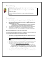
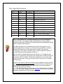
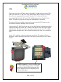
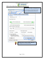
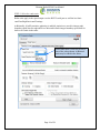
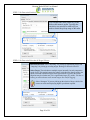
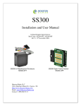
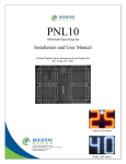
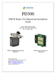
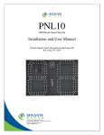
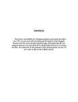
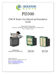
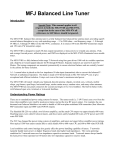
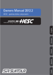
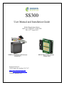
SS300 User Manual and Installation Guide K-Band Doppler Speed Sensor Built Type: SS300-DFT, SS300-OFD Rev 8, 22nd August 2012 SS300 in Weatherproof Enclosure SS300-DFT Houston Radar LLC 12818 Century Dr. Stafford, TX 77477 Http://www.Houston-Radar.com Email: [email protected] Contact: 1-888-602-3111 SS300 Open Frame Version SS300-OFD This device complies with part 15 of the FCC Rules. Operation is subject to the following two conditions: (1) this device may not cause harmful interference, and (2) this device must accept any interference received, including interference that may cause undesired operation. Changes or modifications not expressly approved by the party responsible for compliance could void the user's authority to operate the equipment. Any modification or use other than specified in this manual will strictly void the certification to operate the device. This device carries FCC modular approval and as such is labeled with FCC ID TIASS300. If this label is not visible when the module is installed inside another device, then the outside of the device into which the module is installed must also display a label referring to the enclosed SS300 module. This exterior label can use wording such as the following: “Contains Transmitter Module FCC ID: TIASS300” or “Contains FCC ID: TIASS300.” Any similar wording that expresses the same meaning may be used. Warning: SS300-OFD radar is supplied in an open frame format with exposed antenna and electronics and thus is a static sensitive device. Please use static precautions when handling. Warranty does not cover damage caused by inadequate ESD procedures and practices. Note: Specifications may change without notice. Note: Not liable for typographical errors or omissions. Table Of Contents INTRODUCTION............................................................................................................. 5 INSTALLATION .............................................................................................................. 5 MOUNTING: ..................................................................................................................... 5 DIRECTION POINTING:...................................................................................................... 6 RECOMMENDED ENCLOSURE FOR THE SS300-OFD:........................................................ 6 HOOKUP: .......................................................................................................................... 7 Power Input: ............................................................................................................... 7 Serial Connection: ...................................................................................................... 7 Measured Speed Output:............................................................................................. 7 Setting variables from an ASCII Terminal program via ASCII commands: .............. 8 WIRE SIGNAL DESCRIPTIONS: ........................................................................................ 10 USE ................................................................................................................................... 11 Internal Clock: .......................................................................................................... 12 Configuring the Unit:................................................................................................ 12 Configuring the Radar via the provided Houston Radar Configuration Tool GUI: 15 STEP 1: Connect to Radar ........................................................................................ 16 STEP 2: Click on Radar Setup to bring up the configuration GUI .......................... 17 STEP 3: Select the radar units .................................................................................. 18 STEP 4: Set the radar cutoff speeds (low and high speed cutoff)............................. 19 STEP 5: Set Detection Sensitivity ............................................................................. 20 STEP 6: Set Detection Direction & Target Selector ................................................ 20 STEP 7: Set “Slow Speed Targets Filter” and “Tuning Fork Mode ........................ 21 STEP 8: Setup Baud Rate, ASCII Format and Output Precision ............................. 22 STEP 9: Select Speed Measurement Mode ............................................................... 23 STEP 10: Configure the trigger outputs ................................................................... 24 STEP 11: Select the light sensor type ....................................................................... 25 STEP 12: Select RS232 (serial data output) mode ................................................... 25 STEP 13: Select radar power down mode ................................................................ 26 STEP 14: Disable microwave transmitter (testing only) .......................................... 26 STEP 15: Show Rotary Switch GUI (if rotary switch connected) ............................ 27 STEP 16: Using the Optional Rotary Switch GUI .................................................... 28 STEP 17: Optional Advanced In-Radar Traffic Statistics logging ........................... 30 SS300 SPECIFICATIONS ............................................................................................. 31 GENERAL ....................................................................................................................... 31 APPROVALS ................................................................................................................... 31 DATA INTERFACES ......................................................................................................... 31 MECHANICAL ................................................................................................................. 31 PERFORMANCE ............................................................................................................... 32 APPENDIX A: HOOKING UP TO THE TRIGGER OUTPUTS ON THE RADAR ........................................................................................................................................... 33 APPENDIX B: OPTIONAL BREAKOUT IO BOARD CONNECTIONS: ............. 34 OPTIONAL BREAKOUT IO BOARD CONNECTIONS: ........................................ 35 APPENDIX C: KEEPING TIME WITH AN EXTERNAL CLOCK BACKUP BATTERY ....................................................................................................................... 36 INTRODUCTION Congratulations on your purchase of the Houston Radar directional Doppler Speed Sensor SS300. This state of the art 24GHz K-band microwave Doppler radar is specifically designed for the license free battery operated speed measurement and monitoring market. Utilizing high performance, ultra low power DSP (Digital Signal Processing) technology and microwave components based on a planar patch array antenna with integrated low power PHEMT oscillator, you will find that this high quality product meets your exacting standards for performance and reliability. Some of the highlights of this product include: Complete speed output Doppler radar with digital processing Best in class low power usage of only 9 mA at 12VDC (0.1 Watt) Unprecedented small size to allow incorporation into virtually any location Advanced DSP based algorithm yields consistent performance and speed detection Typically 90+ m (300+ feet) of pickup distance for incoming vehicles on open and level road. Trucks picked up at 450+ feet (137+ m) One RS232 and two ‘open collector’ vehicle detection trigger outputs Radar internal software is upgradeable in the field via RS232 PC interface. Optional rotary/thumbwheel switch input allows changes to speed threshold Optional ambient light sensor input and PWM dimming control. All radar configuration parameters can be set by user via RS232 serial port. Extensive built-in self test. Now Available! Our popular Advanced In-Radar traffic statistics INSTALLATION Mounting: SS300-OFD is supplied in an “open frame” format. It requires a weatherproof enclosure before it may be used outdoors. Alternatively it may be mounted as a component in another product that already has a weatherproof enclosure. The SS300-OFD should be mounted such that the connector points left or right as shown in the picture on the front page. The SS300-DFT is supplied in a weatherproof encapsulated enclosure with a pigtail connection. This unit may be mounted outside without any further protection from the environment. The SS300-DFT should be mounted such that the text “Houston Radar” on the face of the unit is horizontal. The unit may be rotated 90degrees from the suggested optimal mounting. However, in this case, the detection range may be reduced by about 25%. Direction Pointing: The SS00 is directional in nature. It may be configured to detect and measure the speed of incoming or outgoing traffic. It then rejects traffic moving in the opposite direction. Direction of detection is configured via a bit in the MO variable in the radar. If you are collecting traffic statistics, you must configure it for incoming direction. For optimal performance: Radar should be mounted as suggested in the section titled “Mounting” earlier Radar should be pointed into the direction of the oncoming traffic. Radar should be placed along the side of the road to minimize the angle of the oncoming traffic to the radar. o If radar cannot be placed right along the side of the road, it should be pointed at least 100-150 feet up the road into oncoming traffic. The radar may pickup rotating fans. Avoid pointing it at fans or compressors. Radar should be mounted at least 3 feet high from the road for optimal performance and at least 5 feet off the ground for maximum pickup distance Recommended Enclosure for the SS300-OFD: The SS300-OFD radar needs to be enclosed in a weatherproof enclosure for outside use. The following needs to be observed for optimal performance: 1. The front face of the radar (with the golden pads) is the antenna and is the face that must point into traffic. 2. Any cover or window in front of the unit MUST be at least ¼” away from the face. 3. Do NOT spray any conformal (or other) coating, paint or other substance on the antenna. 4. The optimum material to use as a front window is Lexan (Polycarbonate) plastic. 5. The optimum thickness of the polycarbonate window is half wavelength at 24.125Ghz or about 3.5 to 3.7mm (0.137” to 0.146”) thick. a. Alternatively a thin window of any plastic material may be used. The maximum thickness in this case should be no more than 1 mm (40 mils). b. Standard 0.25” thick Lexan should be avoided as it has particularly high reflection coefficient due to this specific thickness. 6. Other plastic materials may be used as a front window, but the optimum thickness will wary with the material’s dielectric constant. Please contact us for details. Alternatively, you may consider weatherproof version SS300-DFT that is available from Houston Radar. Hookup: Power Input: The SS300 radar features wide operating input voltage range of 5.5V-18V. In a typical application it may be powered from a nominal 12V DC source and will feature best in class operational power consumption of 9mA (average). There is no other radar in the world that even comes close to this ultra-low power usage. Competing products may consume up to 20 times more power. This ultra low operational power translates directly into a longer battery life or gives you an option to power the unit from smaller batteries and smaller solar panels. Note: The radar employs aggressive power saving measures that include turning off parts of the circuit that are not being used at any instant. To get a true measure of the power usage of the circuit use a multi-meter that has an averaging function and does not suffer from autoranging during measurements. Otherwise you will get current readings that fluctuate from 4 mA to 18 mA. Note: when the under-voltage lockout (UVL) feature is activated, the operating voltage range is reduced to 8.5V-18V and dropping the input voltage to 4.5V-6.5V will put the radar into a sleep mode where it will update the internal clock. UVL mode is the default from the factory in radars shipped from Dec 3rd 2010 and may be disabled by a bit in MD variable (see later section). Your power supply to the radar must be capable of supplying up to 40mA of current for up to 5 seconds at a time (startup current is higher as the radar is initializing its internal systems). Serial Connection: The SS300 features an RS232 interface that is used to output speed, access statistics data and configure the unit as explained later in this document. The RS232 interface is factory set to default to “cable detect” mode and will power the interface chip down to save power if the radar RX line is not connected. Cable detect mode may be disabled and the interface may be forced ON via a bit in the “MD” variable. Measured Speed Output: The SS300 will send out the measured speed via the ASCII interface as a 3 digit speed with an optional direction indicator. The format is: [?,+]nnn[.ddd][\r,\n] The format of the speed output can be adjusted to any combination of: “?”: Optional prefix sent when 000 selected to be sent when no vehicles are detected “+”: Optional prefix sent when nnn speed is sent for incoming vehicles “nnn”: Three digit ascii speed in the units selected via the UN variable “.ddd”: Programmable number of digits (0-3) after decimal point “\r”: Carriage Return character, optional line ending “\n”: Line Feed character, optional line ending At least one or both of the line endings must be selected with ASCII format. No line ending is not an option. Please see serial port configuration section for details on how to select the above format. Alternatively, the radar may be set to output a single byte speed in binary format. No line termination is issued when format is set to binary. A fractional value cannot be output when the binary output mode is selected. Setting variables from an ASCII Terminal program via ASCII commands: All the radar variables can be set and queried via a simple ASCII command set over the serial port. ASCII commands may be issued via an ASCII terminal program like Hyperterminal or Teraterm Pro. Alternatively, you may issue these commands from an attached microcontroller. All settings are written to FLASH memory and are non-volatile. Do not update settings on a periodic basis, e.g. every second or every minute. Only change settings when the user needs it. The FLASH memory has a limited number of write cycles and will wear out with excessive (>10,000) number of writes. On the other hand, setting the variable to the same value repeatedly is OK because the radar recognizes that the variable has not changed and does not update it in FLASH. The ASCII commands are: get (to get a config variable) set (set set a config variable to a supplied value) reset (resets the radar. Required after changing variables MO, MD and RS, RA(for DR series radars only). LO, HI, SP, ST, SF, UN do not require a reset). info (print out some info about the radar. Info is in the format of <tag>=<value>). New tags may be added in the future. Order of tags may be moved around. e.g. To set a variable (variables are documented in the user manual): set: <case sensitive var name> <value>[Enter] e.g. set:LO 5 alt format: set:LO=5 sets the low speed cutoff to 5 etc. Variables are case sensitive. Commands are not. Success is indicated by an "OK". Failure is indicated by either: "ERROR" - Command was recognized but some other error occurred (variable not present, format not correct etc.) <nothing returned> - Command was not recognized. Entire line was silently discarded. This ensures that spurious things like enters or other ASCII chars do not generate "ERROR" when you are not expecting them. To get a variable: get:<case sensitive var name>[ENTER] e.g. get:LO returns LO=5 (if value is presently set to 5). If sending the ASCII command via an attached microcontroller, the “[ENTER]” key press should be replaced by the carriage return and/or line feed ASCII character. Wire Signal Descriptions: Connector Pin # 1 Signal Name GND Direction Description PWR Radar GND (battery “–“ terminal) 2 3 4 N/C I/O0 I/O1 N/C I/O I/O Do not connect Reserved for future use Reserved for future use 5 6 I/O2 I/O3 I/O I/O Reserved for future use Reserved for future use 7 Trig O/P 1 Output “Open Drain Output 1”. See Note 1. 8 Trig O/P 2 Output “Open Drain Output 2”. See Note 1. 9 RS232 TX Output RS232 Transmit Signal from radar 10 RS232 RX Input RS232 Receive Signal into radar 11 VCC PWR +5.5 to +18VDC Power Supply 12 GND PWR Radar GND (battery “-“ terminal) (wrt Radar) Note 1: See Appendix A for detailed description on how to hookup an external device to be triggered when radar detects incoming objects. Incorrect hookup may result in the output devices being destroyed and will not be covered under warranty. The SS300 features two low impedance outputs that can trigger/turn on an external display/device to bring it out of power saving mode when a vehicle is detected. Both outputs are under radar software control and the typical functionality is to turn both on together when a vehicle is detected. However, if you need different functionality please contact us. When a vehicle is detected and the speed is above the “LO” speed limit and below the “HI” speed limit, both these pins are pulled down to GND and held low as long as a vehicle is tracked. These pins are released as soon as the radar detects no further traffic. This logic may be inverted via a bit in the IO variable. See later section. These are “open drain” (AKA open collector) outputs capable of sinking 130 mA each. You must limit the current externally to ensure that no more than 130 mA goes into each pin when they turn on. They may be connected in parallel to double the sink capacity to 260 mA. The device providing this functionality on the radar board is the ON-Semi “NUD3124” relay driver. Please refer to the datasheet for this device on detailed operating characteristics for these trigger outputs. Houston Radar SS300 User Manual USE Turn on the power to the SS300 to make it operational. No other action is required. The radar will activate OUT 1 and OUT 2 open drain outputs whenever it detects a vehicle that is above the programmed lower speed limit (the “LO” value) and below the programmed high limit (the “HI” value). The default limits are set at 5 and 99 at the factory. The units (e.g. kph, mph, fps, mps) are determined by UN variable. The radar will also keep sending out the speed in user selected ASCII format over the serial interface while an incoming vehicle is tracked. Connect radar to PC RS232 serial port and use provided Windows configuration software to program the high speed limit (“HI” variable). The radar de-asserts the trigger outputs above this limit. If you do not wish an upper detection limit, set this value to 159. This will ensure that the upper limit is never reached regardless if the units are set to MPH or KPH. Set the “LO” variable to set the lower detection speed limit. The outputs will be deasserted for vehicles below this speed limit. The lowest value this may be set is 3 MPH (5KPH). Green LED flashes at 1/3 Hz (12.5% duty cycle) rate when radar is running giving a visual OK signal. In the SS300-OFD version green LED may be installed on the back depending on the requested build option. Page 11 of 38 Houston Radar SS300 User Manual Internal Clock: The radar has a built in clock/calendar function. This is used to keep the time to date/time stamp the historical archive records saved by the Advanced In-Radar traffic statistics collection feature that is available as an option in the radar. The radar does not feature a clock backup battery. So power must remain connected to the radar for the clock to keep time. However an external clock battery may be connected to keep time while radar goes into low power sleep mode. See Appendix C for more details. Configuring the Unit: The radar’s internal parameters may be configured via the radar’s RS232 port after connecting to a PC’s RS232 serial COM port and using the Houston Radar configuration program’s Graphical User Interface (GUI). While this is the most convenient way to configure the radar, customers may also wish to set the configuration variables directly, for example when the radar is part of a system and connected to another microcontroller. The radar configuration variables and their functionality are described below. Configuration Variable Name RS UN LO HI SP SF Description Sets the RS232 serial port’s baud rate and output format. Do not change this value unless you understand the implications. Lower Byte: Sets the internal speed units of the radar. All LO, SP, HI, SI speeds are interpreted to be in this units. 0 = MPH 2=FPS (Feet per second) 1 = KPH 3=MPS (Meters per second) Upper Byte: Sets number of digits after decimal point. Low speed cutoff. Vehicles are not detected below this speed. Minimum value is 2. Should be set to be less than HI. Speeds above this limit trigger the O/P1 and O/P2 outputs and sends ASCII speeds. Note: If the Rotary switch is enabled (See MO bitmask), then the actual Cutoff speed = (LO + Rotary Switch Setting * SI) High speed cutoff. Vehicles are not detected above this speed. Maximum value is 159. Should be set higher than LO speed. Flashing speed limit. Any speed higher than this value “flashes” the trigger output at 50% duty cycle. To “flash” the ASCII speed, 000 are interspersed in the “nnn” speed output on the serial port. Set to HI value to never “flash” the speed output. 1 = Select Fastest Target if multiple targets are detected on the road 0 = Select Strongest Target if multiple targets are detected on the road Page 12 of 38 Houston Radar SS300 User Manual Radar Configuration Variables Continued: Configuration Description Variable Name Target detection sensitivity. Valid values are from 10 to 99 and are a ST percentage of max range. So a value of 50 would yield about 150 feet detection. Note: This is not a range setting but detection sensitivity. Thus if large vehicles are being detected at 400 feet, a value of 50 will reduce detection range for them to approximately 200 feet. Radar mode bitmask. Bits are as follows: MO Bit 0: SI3 ASCII command compat flag. Contact us for more details. Bit 1: Enable ASCII console output on RS232 serial port Bit 2 to 6: Reserved in SS300 radar Bit 7: Enable Rotary Switch on SS300 Break out IO board. Bit 8: Disable power optimized mode. RF ON all the time. Bit 9: Reserved Bit 10: Enable extra filtering for “slow” (<16mph/26km/h) (see note 1) Bit 11: Reserved Bit 12: Detection direction. 0 = only incoming, 1 = only outgoing (see note 2). Bit 13: Gang the effective LO/SP/HI speeds to external Rotary switch. Contact us for details if you wish to change the above speed limits in the field by turning a rotary switch rather than connecting a PC. Radar mode bitmask number 2 (see note 3). Bits are as follows: MD Bit 0: Enable low voltage power down. See Appendix C for details. Bit 1: Enable True Average Speed output (see note 4) Bit 2: Force enable the RS232 interface when set. Sets to “cable detect” mode when bit is cleared. Power usage is increased by 0.012Watts if this interface is force enabled or if RS232 cable is connected. Bit 3: Disable “count up” on startup. This speeds the startup by about 3 seconds (see note 5) Bit 4: Save traffic statistics (if enabled in radar) in 3mph/5kph speed bins rather than original default of 5mph/10kph speed bins (see note 6) Speed Increment of the rotary switch on the optional break out board. SI Effective low speed cutoff in radar = (LO + Rotary Switch Setting * SI) Output Hold Time in seconds. Once the output is triggered, it is held HT for this amount of seconds from the last trigger source before going inactive. Note: Only the digital output is held. The ASCII speed output is not held. The ASCII speed output goes to 000 as soon as target is no longer tracked. Radar IO configuration bitmask. Bits are as follows: IO Bit 0: IO 1 PWM Enable for brightness control. Radars reads the ambient light sensor connected to the IO Break out board and adjusts load brightness via PWM. Full darkness= 5% duty cycle. Full brightness = 100% PWM. PWM Frequency is 240Hz. Bit 1: Set: IO 1 Active high. Clear: IO 1 active low. Page 13 of 38 Houston Radar SS300 User Manual Bit 2 to 7: Reserved Bit 8: IO 2 PWM Enable for brightness control. Radars reads the ambient light sensor connected to the IO Break out board and adjusts load brightness via PWM. Full darkness= 5% duty cycle. Full brightness = 100% PWM. PWM Frequency is 180Hz. Bit 9: Set: IO 2 Active high. Clear: IO 2 active low. Bit 10 to 15: Reserved Configuration Variable Notes: Note 1: “Extra filtering for slow targets” requires firmware version 136 or higher Note 2: Bit 12 of the MO variable sets direction of detection. This functionality is available in firmware versions v115 and higher release date Jan 21st 2010. Older radars may be upgraded to this version. Please contact Houston Radar for a firmware update. Note 3: The bits of the MD variable shown here are only supported in firmware versions 133 or higher release date Feb 1st 2011. Older radars may be upgraded to this version. Please contact Houston Radar for a firmware update Note 4: “True Average Speed” output requires the optional Advanced In Radar traffic statistics collection functionality. Note 5: “Disable Count up” requires firmware version 137 or higher Note 6: “3mph/5kph “high res” traffic stats requires traffic stats to be enabled in the radar and firmware version 138 or higher Page 14 of 38 Houston Radar SS300 User Manual Configuring the Radar via the provided Houston Radar Configuration Tool GUI: 1. Install the provided Houston Radar Advanced Stats Analyzer (or Houston Radar Configuration) Windows program on a Windows 2000, XP, Vista or Win 7 computer. 32 and 64 bit computers are supported. 2. Connect the radar RS232 port to the PC’s RS232 serial port. If the PC does not have a serial port you may buy a USB serial converter dongle (from BestBuy, Radioshack or any Internet store). 3. Power up the radar. Ensure the green LED on the front (side or back as the case may be) flashes every 3 seconds. Power must be provided externally unless you have purchased and are using the Houston Radar powered USB dongle (part #USB-RS-P1) which provides a COM port to the PC and boosts the USB 5V to 12V for the radar all in a single device. 4. Start the Houston Radar Stats Configuration tool program 5. Click on Start->Connect to Radar… 6. Click on “Connect” button. 7. Ensure you see a “Radar found on COM” message. The COM # will depend on your computer 8. Click on OK. Now you are ready to configure the radar. To Radar RS232 + 12VDC Power To Windows PC USB port Houston Radar USB-RS-P1 USB powered RS232 interface to the radar. For a quick and easy connection from a Windows computer to the radar, we suggest purchasing our USB-RS-P1 powered USB dongle (shown above). This device connects to a USB port on a Windows computer and provides a RS232 connection and 12VDC power to all Houston Radar devices. You can be up and taking to the radar within a few minutes of receiving your device. Page 15 of 38 Houston Radar SS300 User Manual STEP 1: Connect to Radar Select your COM port (or “AutoDetect Port” option) and then click on “Connect To Radar”. Click “OK” on the next two boxes. The one on the left shows you information about the radar that you have connected to which you may ignore at this time. Page 16 of 38 Houston Radar SS300 User Manual STEP 2: Click on Radar Setup to bring up the configuration GUI Click on “Radar Setup” to bring up the GUI. You can then set various features in the radar via the different tabs shown here. You must click on “Write To Radar” button for your changes to be saved to the radar. Page 17 of 38 Houston Radar SS300 User Manual STEP 3: Select the radar units Radar units apply to the speed output over the RS232 serial port as well the low limit cutoff and high limit cutoff settings. Additionally, if traffic statistics gathering is enabled, statistics are saved in integer mph boundary speed bins for mph and ft/sec units and in km/h integer boundary speed bins for km/h or m/s units in the radar. Select radar units. Units may be set to one of the values shown. Additional units may be added in the future. Page 18 of 38 Houston Radar SS300 User Manual STEP 4: Set the radar cutoff speeds (low and high speed cutoff) Cutoff speeds affect the measurement range for sending speed out over the serial port and activation of the hardware trigger outputs. Cutoff speeds do not affect collection of traffic statistics in the radar. Traffic statistics are always collection over the entire measurement range of the radar. Thus you can put the radar (or sign) in “stealth mode” by setting the low and high cutoff speeds to the maximum value. This will prevent the activation of the sign, but still allow the radar to collect and save traffic statistics (stats collection option purchase required. Not available in SS300U ultra-low speed radar). Set the minimum speed you wish the radar to pick up and display. This is also the minimum speed that will activate the trigger outputs. You may enter a number, click the up/dn arrows or move the slider. Set the maximum speed you wish the radar to pick up and display. This is also the maximum speed that will activate the trigger outputs. Page 19 of 38 Houston Radar SS300 User Manual STEP 5: Set Detection Sensitivity You can adjust the radar sensitivity via the slider or the numeric up/dn. Typically the sensitivity may need to be reduced if you need to restrict the pickup range of the radar. STEP 6: Set Detection Direction & Target Selector Detection Direction: Select “Incoming” for picking up approaching targets and “Outgoing” for picking up receding targets. Both types cannot be selected. Select Target: The radar detects multiple targets internally, but only outputs the speed of one. This setting instructs the radar to pick either the fastest speed or the speed associated with the strongest return signal which is typically the closest target but may be a farther one if it is significantly larger (E.g. truck). This has no bearing on collected stats as all internal targets are used for logging. Select “Strongest” if you are picking up the wheels of large vehicles like tractors or trucks and displaying higher speeds than expected. Page 20 of 38 Houston Radar SS300 User Manual STEP 7: Set “Slow Speed Targets Filter” and “Tuning Fork Mode If you wish to improve rejection of rain pickup and other low speed “noise” that the radar may pick up, enable this option. When enabled, the radar application logic takes extra long to “validate” targets whose speed is below a threshold (typically 16mph for SS300 radars). This also improves rejection of rain in statistics. However, constant or heavy rain may still get picked up as a target. Directional Doppler radars typically reject tuning forks as they do not appear like a true moving target. If you wish to use a tuning fork to activate the radar for testing purposes, enable this option (if available in the firmware). This will disable direction selectivity for the first 30 seconds after a power up making tuning fork pickup possible. The radar will automatically revert to normal operation after this time. To renter tuning fork mode, power-cycle the radar again. Page 21 of 38 Houston Radar SS300 User Manual STEP 8: Setup Baud Rate, ASCII Format and Output Precision Select the “Data Output” pane You can change the radar serial port (RS232 port) baud rate and speed output ASCII format here. Select how many fractional digits you wish to receive in the speed output. The SS300 radar can send up to 3 places of decimal. “Enable Speed Output” option tells the radar to send out speeds when a target is detected. The AUX com port selection is gray as the SS300 has only 1 RS232 port. Our DR series radars feature 2 RS232 ports. “Disable Countup” option speeds up startup times by about 3 seconds by suppressing the default 0 through10 count-up output over the serial port. Page 22 of 38 Houston Radar SS300 User Manual STEP 9: Select Speed Measurement Mode (Available with ‘Advanced In-Radar Traffic Statistics’ option only) If you have purchased the Advanced In-Radar traffic statistics option, the SS300 can be set to output either real-time target speeds over the serial port, or internally average all traffic speeds over a specified interval (say 30 seconds) and output the average speed. This is very useful for calculating the average incoming speed of the road for congestion or incident detection purposes or for input into “time to destination” type of applications. Targets in all incoming lanes are used to generate this average speed. Page 23 of 38 Houston Radar SS300 User Manual STEP 10: Configure the trigger outputs Start by clicking on “Hardware & IO Config” Tab. The SS300 has two hardware “open drain” trigger outputs that may be used to trigger an external device or turn on 1 or 2 LED lamps to make a stand-alone speed enabled flasher or VATCS (Vehicle Activated Traffic Calming Sign). Simple enable one or both the outputs and they will be activated if a speed is detected between the low and high speed cutoff values. Enable PWM: Check this box if you have a LED lamp connected to the output and wish the radar to adjust the brightness based on ambient light. You will also need to connect a light sensor to the SS300 to measure the light. Blink Output when Triggered: Check this box if you want to make a flasher. The lamp connected to the trigger output will blink when measured speed exceeds the “speed limit” setting. When this box is checked, you can set this limit on the “Detection And Units” tab. Check both boxes if you want to make a “wigwag” (alternating) flasher. Output Hold Time: Set a value here if you want to hold or extend the trigger. This is useful to turn ON an external device for a minimum amount of time when triggered by the radar. If “Blink Output” is checked, the threshold above which the output is blinked is shown on the Speed Detection Limits slider. Page 24 of 38 Houston Radar SS300 User Manual STEP 11: Select the light sensor type If you selected to have the radar control your attached LED lamp’s brightness, you must attached an external light sensor. The radar will then measure the ambient light via this sensor and adjust the “ON” duty cycle via PWM (pulse width modulation). This is done with a frequency of 180Hz so that the attached lamp does not appear to be flickering. There are two types of sensors that may be used, LDR (light dependent resistor) or “IC”. The LDR is much easier to use and mount and available as a flange mounted weatherproof unit from us. The IC type sensor is more linear and calibrated to the human eye, but requires you to place it on an external PCB as it is a fine pitched SMT IC. STEP 12: Select RS232 (serial data output) mode The SS300 radar turns off the internal RS232 serial driver if it does not detect any RS232 voltage level on the RX pin. It automatically powers this chip back up once you plug in a RS232 cable. This saves about 5 to 10% power when you are not connected to the device. However, if you must use the RS232 interface in TX only mode (e.g. connected only RS232 TX and GND to your microcontroller), you must configure the RS232 interface to be “always ON”. Select the type of light sensor you have connected. Only required if you have “Enable PWM” checked in “Trigger Output Configuration” box above. Normally you would connect RS, TX & GND to the RS232 interface. However, if you connect to only TX&GND, you must select “Always ON” else radar RS232 interface will power down. Page 25 of 38 Houston Radar SS300 User Manual STEP 13: Select radar power down mode If radar has “Advanced In-Radar Traffic Statistics” enabled, you must provide an external battery backup to allow the radar clock to keep time (see Appendix C: Keeping Time With an External Clock Backup Battery) in case main power is lost. In this setup, this option must be checked to instruct the radar to go into ultra-low power timekeeping mode when main power is removed and the lower voltage backup power kicks in. Uncheck this option if you want the radar to work normally down to 5.5VDC and not go into low power mode below 7VDC. STEP 14: Disable microwave transmitter (testing only) Check this box in case you wish to turn off the microwave transmitter. This will prevent normal operation of the radar and is provided only for testing purposes. Page 26 of 38 Houston Radar SS300 User Manual STEP 15: Show Rotary Switch GUI (if rotary switch connected) The SS300 radar measurement speed limits (including the blinking speed limit) may be set/changed in the field via a convenient rotary switch. This avoids having to connect a computer to the radar/sign to make this change. This rotary switch is present on the optional IO Breakout board or you may use your own switch. However, you must first setup the radar to use this rotary switch. If you wish to use this feature, check the “Show Rotary Switch GUI” to bring this interface up. The above GUI interface is shown when you check the “Show Rotary Switch GUI” checkbox. You can now enable the rotary switch and set the limits as explained below. Page 27 of 38 Houston Radar SS300 User Manual STEP 16: Using the Optional Rotary Switch GUI (Applicable only if you wish to use a rotary switch). Enable the rotary switch and decide if you wish to control all 3 limits or only the lower cutoff limit. The blue underline changes to reflect your selection. Next pick a rotary switch increment. This is the speed step added with every turn of the rotary switch. Page 28 of 38 Houston Radar SS300 User Manual Rotary switch GUI setup continued… Finally pick the low speed cutoff, flashing speed limit and high speed cutoff for the rotary switch at position 0. In the graphic shown, in position 0, the radar will display speeds (and trigger output) between 10 and 55kph. It will blink the trigger output above 30 mph. Then for every turn of the switch, all limits will be shifted up by 5mph (the increment value). Click this button to display the effective limit values when the rotary switch it turned. It may be convenient to print this table and use it as a handy reference in the field. Alternatively, click “Check Limits” and turn the “Test Rotary Switch Position” spinbox and see the limits change on the GUI. Page 29 of 38 Houston Radar SS300 User Manual STEP 17: Optional Advanced In-Radar Traffic Statistics logging If statistics logging is enabled in your radar (a separate purchase option), select how long you wish the radar to collect data in speed bins before it saves off the log to internal flash memory and starts a new record. This may be set as fast as 1 minute. We do not recommend setting this to greater than 15 minutes, as the storage mechanism can only log a maximum of 255 vehicles in each speed bin. Hence you must ensure that the traffic density cannot exceed 255 vehicles per speed bin per record interval. Note that the supplied Windows analysis program can aggregate multiple bins and generate reports in half hour or hourly intervals, but (obviously) it cannot disaggregate longer bins into finer resolutions once the data has been saved in the radar. The table shows the tradeoff between logging interval and storage space. Record Interval (min) 1 5 10 15 30 Number of Days Before Rollover 12 60 120 180 360 Firmware version 138 and higher support “high-res” compressed logs. Stored records may be read by clicking on the “Read Traffic Stats From Radar” button location on the “Connection” tab When this option is enabled, data is binned in 3mph/5km/h bins rather than 5mph/10km/h bins. Page 30 of 38 Since, this generates significantly more data; the logs are also compressed to save space in flash memory. Houston Radar SS300 User Manual SS300 SPECIFICATIONS General Operating Band Frequency RF Power Output Antenna Beam Pattern Polarization Supply Voltage Reverse Battery Nominal Current Draw Operating Temp. Weatherproof IR Remote Programmable K-Band 24.125 GHz 50Mhz (US), 24.200Ghz on request 5mW 45deg x 38 deg Linear 5.5V DC to 18V DC Protected 9 mA avg. (+/-1ma,) (@+12V DC) -22F to +185F (-30C to +85C). Electronics designed and tested to –40C. Yes (SS300-DFT build option). Open frame also available. No Approvals Approvals FCC Part 15, modular approval (US Version), CE Mark. Data Interfaces Serial Communication Data Rate Data & Pwr Connector RS232 Baud Rates from 1200 to 115200 baud SS300-OFD:Molex “C Grid SL” male shrouded 12 pin RA part #70553-0011 SS300-DFT:Molex “C Grid SL” female 12 pin (mate to above #) Mechanical Weight Dimensions Cable Exit Mounting approx 33 grams (1.16 oz) 2.1”x1.75”x0.6” (LxWxD) 52 x 46 x 16mm SS300-OFD: Side via right angle connector SS300-DFT: Encapsulated cable from back Four #2-56 standoff’s embedded on module Specifications continued on next page … Page 31 of 38 Houston Radar SS300 User Manual Performance Speed Measurement Range 1.3mph to 100 mph (2.1km/h to 161 kph). 0.25mph to 16mph “SS300U” option available. Resolution 0.006 mph Accuracy 0.5% of reading + 0.1mph Detection Range Typically 90+ m (300+ feet) for compact vehicles on open and level road with radar mounted 1.5 m (5 feet) high and pointed straight into oncoming traffic. 150+ m (500+ feet) for larger trucks, lorries and vehicles with inherently large radar cross-section. May vary with installation and road conditions. Detection range specified is typical for speeds between 20kph and 88kph (12 to 55 mph). It tapers off below and above this speed range. At the low end of the speed range (2mph (5kph), the detection range is about 34+ m (110+ feet). SS300 is not recommended for roads with speeds above 90 kph (56 mph) due to reduced range and tracking time. Contact factory for a different radar version if you need to detect vehicles outside said speed range. Page 32 of 38 Houston Radar SS300 User Manual Appendix A: Hooking up to the trigger outputs on the radar The SS300 radar features two “open drain” outputs. The device used for this purpose is the On Semiconductor relay driver NUD3124. The output configuration of this device is shown below (from the On Semi datasheet). The two outputs O/P1 and O/P2 are brought out on the radar connector pins (see IO connector pin out in manual for connector pin numbers). This device can sink 130mA of DC current at up to 28VDC. However, these are low impedance outputs, which means that you must externally limit the maximum current that will flow into these outputs to 150mA at the worst-case head voltage. They may be parallel together to increase this value to 300mA. There are two ways to ensure this: 1. Connect an output device that is rated to draw no more than 150mA at your supply voltage (+Vhead). This device can be powered up to 28VDC. For example, this can be a 12 or 24VDC relay coil rated at more than 150 mA coil current or 2. Connect an external resistor in series with the output load and the O/P1 or O/P2 pins. The value of this external resistor should be calculated as follows (ohms law): R (in K Ohms)= (Vhead –Vload drop)/150 +Vhead Load Method 1 +Vhead Load rated to draw max of 150mA at +Vhead max Load Resistor Page 33 of 38 Load Method 2 Houston Radar SS300 User Manual Appendix B: Optional Breakout IO Board Connections: (Non-Isolated Mosfet version with PWM Brightness Control) Connecting the load to the High power and trigger outputs: You may directly connect your high power DC load + & - to J5. The load is activated via fuse F1 when the output is triggered. You may directly connect a <150mA relay coil or other low power load to the J4 & J6 connectors. The + load terminals are always wired to VCC. The (-) terminals are connected to GND when a vehicle is detected and the output triggered. J5 is always triggered at the same time as J6. Page 34 of 38 Houston Radar SS300 User Manual Optional Breakout IO Board Connections: (Isolated Solid-State Relay version, AC or DC capable) Optional Isolated IO Board. Note: PWM Brightness Control is NOT available with Isolated AC/DC Relay outputs. Page 35 of 38 Appendix C: Keeping Time With an External Clock Backup Battery Our popular “Advanced In-Radar Traffic Statistics” is available as an option in the SS300 radar as well as the PNL10 display (which uses the SS300 radar as the speed measurement element). The In-Radar traffic statistics option generates time-stamped historical records that are saved in the on-board FLASH memory. Hence, the SS300 radar needs to keep calendar date and time once it is set from a device (typically a PC running our configuration or stats analyzer software). If the SS300 is used in a configuration that may disrupt power, an external clock backup battery must be connected as suggested below. Note: Alternatively the clock may be manually reset from an external controller to the correct time once power is restored. Step 1: Set the “Enable Low Power Sleep” mode bit in the MD variable (this is factory default so no operation is required if you have not changed it). The radar will now enter low power sleep mode where it will maintain the clock once the external VCC supply voltage enters the sleep region as shown in the provided diagram. The radar will resume normal operation once the input VCC voltage returns to the “Run” region. Step 2: Setup an arrangement to switch in a 4.5V to 6.8V clock backup battery into the VCC line once main power is removed. This may be done two ways: Method 1: “Wire OR” the backup source and the main VCC through two low drop diodes as shown on the next page. Diode voltage drop must be taken into account when determining backup voltage. For example if the diode voltage drop is 0.6V the backup supply voltage must be between 5.1 and 7.4 volt. We recommend a low drop (<0.3V) low leakage diode particularly for the clock battery when using a lithium battery that cannot tolerate any significant reverse charging current. Method 2: If the main supply will not be removed, but rather switched off, install a Zener diode across the power switch such that the radar continues to receive between 4.5 and 6.8VDC when the power is turned off via the switch (with the rest dropped by the zenner). The power consumed by the radar in low power sleep mode is as follows: Installed Configuration Micro Amps Sleep Mode Sleep Mode Consumed in sleep Enter Voltage Exit Voltage Stand Alone SS300 Radar 7V nominal. 8V nominal. 165 uA 15 A 6.5V min 8.7V max SS300 in PNL10 display 7V nominal 8V nominal. 745 uA 20 A 6.5V min 8.7V max Houston Radar SS300 User Manual Note 1: Connecting a RS232 cable to the radar or forcing the RS232 interface to ON does not affect the sleep power usage. Note 2: The radar power usage is approximately constant regardless of the input supply voltage in the sleep region. This is different when the radar is in the operational region where is behaves as a constant power device (current goes down with increasing voltage). Method 1 to provide clock backup power (Wired OR with two supplies): SS300 Standalone Low Drop voltage diodes to Wire OR the batteries. +VCC D2 + OR D1 + PNL10 Display GND Clock Backup Battery (4.7V to 6.7V assuming 0.2v diode drop). Main Battery (8.6V to 18 V. May be removed. Backup battery will provide power to maintain clock. Ensure it cannot be removed or disconnected. Note: Please use low forward voltage drop diodes to maintain efficiency. Also carefully consider the reverse leakage currents if using a lithium backup battery which is very intolerant of such currents. D1 could be a signal diode that has very low reverse currents. D2 needs to be rated for >=1A. Method 2 to provide clock backup power (main supply switched off but not removed): Zener diode to drop enough voltage from main battery to supply between 4.5V and 6.5V to SS300 * See Note 1 SS300 Standalone +VCC + OR PNL10 Display GND Main power ON/OFF switch puts SS300/PNL10 into low power sleep mode when turned OFF. Zenner still provides enough voltage and current to allow SS300 to keep time with minimal power usage. Note 1: The zenner value should be “X” and satisfy the following two equations: Eq1 fully charged battery: Bmax – X = 6.5 to 4.5 Eq2 fully discharged battery: Bmin – X = 6.5 to 4.5 Page 37 of 38 Main Battery (8.6V to 18 V. May NOT be removed if time is to be maintained when switch is in OFF position.