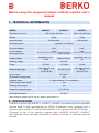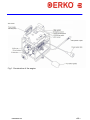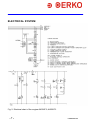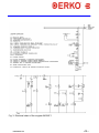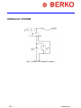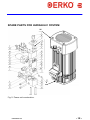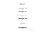
1
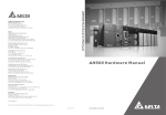
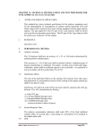
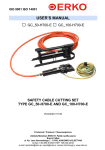
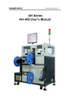
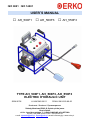
ISO 9001 ISO 14001 USER’S MANUAL □ AH_500F1 □ AH_500F3 □ AH_550F3 TYPE AH_500F1, AH_500F3, AH_550F3 ELECTRIC HYDRAULIC UNIT SWW 0792 # VAH304010611 PKWiU 29.56.25-90.00 Producent / Producer / Производитель Zakłady Metalowe ERKO R. Pętlak spółka jawna Bracia Pętlak ul. Ks. Jana Hanowskiego 7, 11-042 JONKOWO k/OLSZTYNA tel./fax (+48) 089 5129273 NIP: 739-020-46-93 e-mail: [email protected], [email protected] serwis informacyjny: www.erko.pl. Dziękujemy za zakup naszego urządzenia. Prosimy o uważne przeczytanie instrukcji użytkowania oraz zaleceń eksploatacyjnych. Thank you for buying our product. Before using this equipment, please carefully read the user and the maintenance manuals. Благодарим за покупку нашего оборудования. Просим внимательно прочитать инструкцию пользователя, а также рекомендации по эксплуатации * Firma ERKO sp.j. zastrzega sobie prawo do wprowadzania zmian konstrukcyjnych wynikających z modernizacji wyrobów. * ERKO has the right to introduce construction modifications due to equipment modernization. * Фирма ERKO sp.j. остовляет за собой право для введения конструкционных изменений вытекающих из модернизации изделий. ISO 9001 ISO 14001 # VAH300091118 -2- INDEX 1. 2. 3. 4. TECHNICAL INFORMATION..............................................................................4 APPLICATION.....................................................................................................5 INSTALATION.....................................................................................................5 CONSTRUCTION...............................................................................................5 CONTROL PANEL.....................................................................................................5 ELECTRICAL SYSTEM.............................................................................................7 HYDRAULIC SYSTEM...............................................................................................9 SPARE PARTS FOR HYDRAULIC SYSTEM..........................................................10 5. INSTRUCTIONS FOR USE..............................................................................12 6. WORK WITH QUICK COUPLERS....................................................................12 7. MAINTENANCE AND OPERATION RECOMMENDATIONS...........................13 8. TROUBLESHOOTING......................................................................................15 9. IMPORTANT NOTES........................................................................................15 10. DISPOSAL........................................................................................................15 11. HEALTH AND SAFETY RECOMMENDATION................................................16 -3- # VH700091118 Before using this equipment please carefully read the user’s manual. 1. TECHNICAL INFORMATION MODEL Dimnsions (d x s x h) AH500F3 AH550F3 525 x 410 x 625 mm 42 kg 42 kg Weight Nominal output AH500F1 525 x 410 x 625 mm 3 1,33 dm3/min 0,66 dm /min Working medium Hydraulic oil L-HM 22 Oil tank capacity 5 dm3 5 dm3 Useful capacity 2 dm3 2 dm3 Working pressure Supply voltage 380 / 630 bar 3x400/230 V AC, 50 Hz 230V AC 50 Hz Steering voltage Power Electrical plug type 24 V DC 0,75 kW. 16A 400V 3P N+E IP44 (PCE 015-6v) 0,75 kW 1,0 kW. 16A 2P+E IP44 16A 400V 3P N+E IP44 (PCE 015-6v) Type of work S3- 40% * IP protection rating code Hydraulic hose 3x400/230 V AC, 50 Hz 40 1 x high pressure 2,5 m (standard) Power supply cable lenght 3m Steering cable lenght 3m Socket for external sensor Working temperature JC 6,35 mm -25÷40°C * With cooling fan applied, type of work S1, apllies to performance F3 2. APPLICATION Hydraulic engines type AH500F3, AH500F1, AH550F3 are electrically driven portable devices used to feed manufactured by ERKO ® hydraulic tools, equipped with a hydraulic quick coupler PT and fed with hydraulic oil at a pressure of 630 or 380 bar. Principles of use of the hydraulic engines type: AH550F3, AH500F3, AH500F1 with particular tools has been specified in relevant manuals of particular external devices. -4- # VAH300091118 3. INSTALATION AH500F3 and AH550F3 engines require five-wire mains L1, L2, L3, N, PE, order is not relevant. In the case of four-wire mains, it is necessary to bridge PE and N conductors in the output socket, which can be made by a person with appropriate qualifications. Engine type AH500F1 require three-wired network L1 N and PE. It is unacceptable to use output sockets without grounding. 4. CONSTRUCTION The engine has a compact structure based on frame construction where a compact hydraulic engine and electric power supply – control panel is mounted. The wires are led from the unit: Power supply cable for connection to the mains; Control cable terminated with foot switch (pedal); High pressure hydraulic hose terminated with hydraulic coupler type PM. CONTROL PANEL Control panel of the hydraulic engine is equipped with: • • • • • • • Main switch: it serves to bring / cut power to the control system. When switched on, the "power supply indicating lamp" lights up. Switch 630/380 bar: it serves to set the pressure of the unit. Two positions are possible, setting at 630 bar and 380 bar setting. The setting 380 bar of the 630/380 switch initiates the pressure control system, which cuts off the power from the pump motor when pressure 380 bar is reached. The setting 630 bar of the 630/380 switch disconnects the pressure control system. The pressure of 630 bar is adjusted by overflow valve of the hydraulic system. Power supply indicating lamp: Informs that the engine is ready for use (lamp lighted – engine ready for operation) Failure indicating lamp: informs that the maximum operating temperature has been exceeded. The device cannot be activated until the oil reaches temperature safe for operation. Emergency switch: Used to switch off the engine in case of an emergency. It switches off the control system leaving power supply system live. Foot switch (pedal): Used to activate hydraulic pump (pump is activated when pressed – oil is being pumped / released - the pump stops automatically, oil is drained from the tool back to oil tank). Jack socket: This port is used to maintain communication between external device and the unit. Communication is one-way, two states of on / off. The signal allows to stop and start the unit. -5- # VAH300091118 Fig.1. Construction of the engine # VAH300091118 -6- ELECTRICAL SYSTEM Fig. 2. Electrical chart of the engine AH500F3; AH550F3. -7- # VAH300091118 Fig. 3. Electrical chart of the engine AH500F1 # VAH300091118 -8- HYDRAULIC SYSTEM Fig. 4. Chart of the hydraulic system -9- # VAH300091118 SPARE PARTS FOR HUDRAULIC SYSTEM 26 1 4 Fig. 5. Power unit construction. # VAH300091118 - 10 - 1 2 3 4 4 4 5 6 7 8 9 10 11 12 13 14 15 16 17 18 19 20 21 22 23 24 25 26 No. AH5 AH5 AH5 00F 00F 50F 3 1 3 1 1 1 1 1 1 1 1 1 1 1 1 1 1 1 1 1 1 1 1 1 1 1 1 1 1 1 1 1 1 1 1 1 1 1 1 1 1 1 1 1 1 2 2 2 2 2 2 4 4 4 8 8 8 1 1 1 3 3 3 2 2 2 3 3 3 2 2 2 1 1 1 2 2 2 * * * Quantity Pin Electric valve unit Pressure control unit Oil feeder Oil feeder Oil feeder Plug Plug Cap Pressure control Electric valve Frame of connection Base unit Overflow valve Pressure plate Washer Screw Screw Screw Bolt O-ring O-ring O-ring O-ring O-ring O-ring O-ring Cooling fan Name of element AH400-01-03-01 AH300-01-03-06-A AH300-01-03-05-B HAWE_KA-281-L1KT-AH550-3F HAWE_KAW241-L1KT-AH500-1F HAWE_KA-241-L1KT-AH500-3F HOKO_G14-ED-40 HOKO_VSU-14-70 HAWE-7250-015 HOAH_DG33-24 HAWE-G3-0-G24 HOPP_S10-G14-70 AH300-01-03-07 HAWE-A2-700 HAWE-7250-014 HAWE-RING-U87-16-1 NEZS_WNI-M6-50-8.8OC NEZS_WNI-M6-40-8.8OC NEZS_Wl-M4-20-8.8OC NEZK_S2-3-8 HUTR_0R1200350-N90 HUTR_0R1500500-N90 HUTR_0R1500600-N90 HUTR_0R1501100-N90 HUTR_0R2001400-N90 HUTR_0R1500150-N90 HUTR_0R2000800-N90 HAWE_KA2-WENTYLATOR ID numer of element * additional equipment - 11 - # VAH300091118 5. INSTRUCTIONS FOR USE 1. Before starting the engine an examination should be carried out to eliminate external mechanical damage. 2. Check the oil level. It should be between 5 ÷ 15mm from the top of the oil level indicating tube. If it is not, it should be filled up. (Do not rely on the markers on the indicator) 3. Connect the unit to the mains. 4. Connect the equipment. Attach the selected head (tool) to the high pressure hose (quick coupler type PM works only with quick coupler type PT of an external device) and connect the communication cable to the external device jack socket (if the cable is supplied with the device). 5. Turn the main switch to position I. 6. Turn the "630/380 bar" switch to the desired position choosing between 630 or 380 bar working pressure (according to user’s manual enclosed to the engine 7. In order to activate the pump press the "foot switch" (pedal). 8. To stop the engine, release "foot switch". If the engine is connected to the receiver, the hydraulic part of the tool will come back to its initial position. 9. If the engine uses a cable for communication with an external device: engine’s pump will stop after receiving a signal from an external device. The hydraulic part of the tool will come back to its initial position once the “foot switch” is released. 10. Before disconnecting the external device from the egine, it has to be ensure that the hydraulic part of the tool came back to its initial position. 11. Having disconnected the engine from the tool the coverr should be immediately put on the quick couplers PT (of a tools) and PM (of the engine). 12. After operation, turn off the power supply with the "main switch" and disconnect the engine from the power source. 6. WORK WITH QUICK COUPLERS To connect the external device: Remove the cover from PT and PM quick couplers Press the PT quick coupler into PM quick coupler till they are connected (turn the ring of PM quick coupler). In order to disconnect: Turn the sleeve of the PM quick coupler so that the notch on the sleeve matches with a bead on the PM’s body # VAH300091118 - 12 - Pull the sleeve as indicated on the Fig. 6. until the quick couplers are disconnected Fig. 6. Work with quick couplers 7. MAINTENANCE AND OPERATION RECOMMENDATIONS 1. 2. 3. The power unit should always be placed vertucally (acceptable deviation ±15°) in rooms with air circulation. After falling, the power unit should be placed in the working position. Wait for approx. 1 min untilo the oil stabilizes. Check oil level and refill if required. Switch off the electrical power supply when carrying out any maintenance work; the hydraulic system should be unloaded. 4. The supply generates high pressure. Any pressure leak may result in unforeseen consequences. Exercise special caution when operating the equipment. 5. Upon releasing the seals the operator loses the warranty for the entire hydraulic system. 6. The maximum working pressure was set by the manufacturer at the overflow valve at 450 bar and is not subject to adjusting throughout the operation period (sealed). - 13 - # VAH300091118 7. The oil should be changed every 12 months. Oil should be in conformity with DIN 51524 part 1 to 4, class HLP or ISO 6743/4 class HM, of the viscosity ISO VG 22,32. Hydrol® L-HM 22 is recommended. Oil is available from ERKO: package of 1dm3- order code OLEJ_HYDR_1, package of 5 dm3 – order code OLEJ_HYDR_5. 8. A tank cleanliness check, tank washing, oil change and hydraulic system inspections are recommended. Every 12 months by serviceman. 9. Maintaining oil purity and periodical oil exchanges have a graet effect on the durability of the hydraulic unit and considerably prolong their performance and reliability. Required oil purity: class 9 (recommended class 8) according to the NAS 1638 norm. 10. Remove air from the pump after an oil refill. To do so: • Fill the entire system, together with the hydraulic hose with oil until it overflows. Connect the quick coupler to the hose. • Connect the receiving device. • Place it below the power unit level. • Start up the pump in short cycles (2 sec.) until the equipment servomotor sticks out to the maximum position. • Then gradually increase the load until the maximum working pressure is obtained (oil overflows the overflow valve) and the pump is working evenly and quietly. • In case of the power unit loud and uneven work and no power, the air removal operation should be repeated. NOTE: Skipping this procedure will prevent obtaining working pressure level and in extreme situations will result in pump seizure. 11. When operating the power unit, check the system leak-tightness every day and regularly remove leaks of oil and check its level in the tank. 12. In case of electric hydraulic unit failure, switch off electrical power supply and contact the specialized service. Repairs within the warranty period can only be carried out by manufacturer or its authorized representatives. 13. Protect the equipment against the influence of atmospheric factors, corrosion, debris and mechanical damage. If the power unit becomes wet, it should be dried and when it becomes dirty, it should be dryclead=ned. When not used for longer periods, store the equipment in a clean and possibly dry place. Proper maintenance and operation considerably extends the life of the power unit. # VAH300091118 - 14 - 8. TROUBLESHOOTING Problem Cause Action required The system has insufficient power The hydraulic unit is not free from air. Oil level too low. Pumping piston is damaged. Overflow valve is damaged. Overflow valve is overregulated. Pressure control is damaged. Pressure control is overregulated. Leak. The system is leaky. Overflow valve is overregulated. Problems with the supply. Engine switch is damaged. Contactor is damaged. Engine switch is damaged. Contactor is damaged. Remove air from the system. Refill oil. Select the required oil pressure setting. Contact the service. Lack of one or two phases of supply. Check the power supply. No power supply. Transformer fuse is damaged. Transformer is damaged. Connect to power supply. Replace the fuse. Contact the service. Electrical valve is damaged. The system has insufficient power. CONTACT THE SERVICE. Eak in the hydraulic system Interrupted work of the electric hydraulic unit. The electric hydraulic unit does not work, the black light indicating no phase. The electric hydraulic unit does not work, the red light indicating no phase. After correct connection to the power supply and switching the main switch, the electric hydraulic unit does not start up and the power supply lamp is not lit, there is no signal on the no phase sensor. The electric hydraulic unit pumps oil but deas not supply it to the head. Contact the service. Check the power supply. Contact the service. Contact the service. 9. IMPORTANT NOTES Application of higher pressure in external equipment than that specified in the technical and operational documentation may result in damaging the equipment. 10.DISPOSAL After the end of the exploitation period, utilize or recycle the particular elements of this equipment according to the regulations in force. 'According to the regulations on ZSEiE it is forbidden to dispose the worn out equipment labelled with the crossed basket with other waste. In order to dispose electronic or electric equipment, users are obliged to deliver it to a specialized center collecting worn out eqipment. The above regulatory responsibility was introduced in order to limit the amount of waste of worn out electric and electronic equipment and to ensure the relevant collection, retrieval and recycling levels. Such equipment does not contain dangerous components that would have a perticularly negative effect on the enviroment and health.' - 15 - # VAH300091118 11. HEALTH AND SAFETY RECOMMENDATIONS 1. An AH_400RD hydraulic power unit may be operated by at least 18 years old person, who has been informed about the contents of the Operation manual and has been trained in the work safety principles for the work stand.Proper positioning of the operating elements should be checked prior to starting the power unit. 2. The equipment can be operated only when at full technical performance. 3. Prior to starting up check the following: • electrical system condition • oil level in hydraulic supply unit • state of mobile elements (tools powered by the power system) • hydraulic system condition 4. Electrical power should be disconnected during daily checks and repairs in order to prevent accidental unit starting. 5. Personnel should wear adequate protective gear while operating the equipment. 6. The power unit may only be used for its intended purpose. 7. Prevent debris collection around the unit. If dust concentration is high, cover the equipment. 8. Never start the equipment while completing any maintenance work (assembly, disassembly, positioning the machined materials). 9. Switch the generator on only after assuring that the preparation has been completed and there is no danger of damaging the equipment or wounding any body parts. 10. In emergency situations follow the plant emergency procedures. # VAH300091118 - 16 -