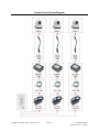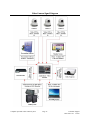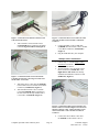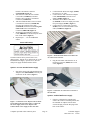
1
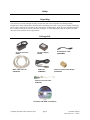
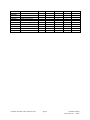
KINGDOM® INCORPORATED
COMPUTER OPERATED VIDEO CAMERA
SYSTEM TM
INSTALLATION & USER MANUAL
Compatibility:
Windows XP, Vista, 7,
& 8 (x64 compatible)
© 2013 BY KINGDOM® INCORPORATED (ALL RIGHTS RESERVED)
NO PORTION OF THIS MANUAL MAY BE REPRODUCED IN ANY SHAPE OR FORM WITHOUT THE
WRITTEN APPROVAL OF KINGDOM® INCORPORATED
Table of Contents
Foreword........................................................................................................................................................................3
Introduction ...................................................................................................................................................................4
About This Manual ....................................................................................................................................................4
Contact Information ...................................................................................................................................................4
Computer Operated Video Camera System Description ...........................................................................................4
WARNING ....................................................................................................................................................................5
Glossary of Terms .........................................................................................................................................................7
Setup ..............................................................................................................................................................................8
Unpacking..................................................................................................................................................................8
Package List ...............................................................................................................................................................8
Assembly ..................................................................................................................................................................... 10
Camera Control System Diagram ............................................................................................................................ 10
Camera Power System Diagram .............................................................................................................................. 11
Video Camera Signal Diagram ................................................................................................................................ 12
Camera Setup ........................................................................................................................................................... 13
Computer Operated Video Camera Setup ............................................................................................................ 13
Inverting the Camera Video Image ...................................................................................................................... 13
Single Camera Installation ................................................................................................................................... 13
Multiple Camera Installations .............................................................................................................................. 14
Power Cable Setup ............................................................................................................................................... 15
Quick Start Guide for the COVCS Software ............................................................................................................... 16
Software Overview .................................................................................................................................................. 16
Minimum Computer Specifications ..................................................................................................................... 16
Computer Video Camera Control Software Installation ..................................................................................... 16
Keyboard and Mouse General Controls ............................................................................................................... 17
Camera Presets .................................................................................................................................................... 17
Camera Preset Labels .......................................................................................................................................... 18
Joystick Control ................................................................................................................................................... 18
Reverse Joystick Direction Controls .................................................................................................................... 18
COVCS Software Terms & Conditions ....................................................................................................................... 19
Important Legal Notice ............................................................................................................................................ 19
Kingdom® Camera Control .................................................................................................................................. 19
Troubleshooting ........................................................................................................................................................... 21
Computer Operated Video Camera System
Page 2
Technical Support
1-800-788-1122 x 2430
Foreword
Thank you for purchasing the Kingdom® Computer Operated Video Camera System (COVCS). This purchase is
your first step in to the world of Computer Operated Video Cameras. This manual is designed to assist you in the
setup and operation of the video cameras(s) and control software for your system. This document will cover
installing the Computer Control Software, setting up the hardware, and finally a basic explanation of connecting
your camera(s) to your video capture device.
Computer Operated Video Camera System
Page 3
Technical Support
1-800-788-1122 x 2430
Introduction
About This Manual
Contact Information
With the user’s experience in mind this manual was
created with accuracy at the forefront. Every effort
has been made to ensure that all instructions, photos,
and documentation are correct. Due to updates in the
software as well as upgrades in video cameras an
occasional mistake may be made.
Kingdom® Inc. will support our products to the best
of our ability. If you have any questions or need
assistance with your camera system feel free to
contact us. To ensure the best quality of support,
please locate your Customer Number or Invoice
Number.
With improvements to both software and hardware,
your system may not look exactly like what is
documented within this manual. If you need any
assistance with an aspect of this manual, please
contact our Technical Support Department or review
the Kingdom® website for updates.
Kingdom® Incorporated
PO Box 506
719 Lambs Creek Road
Mansfield, PA 16933
For Customer Service:
For Technical Support:
For Sales:
1-800-296-2312
1-800-788-1122 x 2430
1-800-788-1122
Computer Operated Video Camera
System Description
This Computer Operated Video Camera System
(COVCS) is designed for the purpose of remotely
controlling Point, Tilt, Zoom (PTZ) Robotic
Camera(s) that has been included with this system.
This system can utilize a Joystick, your existing
computer keyboard, and mouse interfaces. The
operator has the ability to control up to seven (7) PTZ
cameras remotely. Each camera that is attached to
this system may have the ability to be assigned up to
six (6) presets that can be designated by the operator.
Each preset can also be labeled for easy
identification.
Computer Operated Video Camera System
Page 4
Technical Support
1-800-788-1122 x 2430
WARNING
This manual provides critical safety instructions on the proper setup, operation,
maintenance, and service of this system. Save this document, refer to it often,
and use it to instruct other operators. Failures to read, understand, and follow the
instructions in this manual may result in fire or serious personal injury.
The owner of this system is solely responsible for its safe use. This
responsibility includes but is not limited to proper installation in a safe
environment, personnel training and usage authorization, proper inspection
and maintenance, manual availability and comprehension, application of safety
devices, and the usage of personal protective equipment.
The manufacturer will not be held liable for injury or property damage from
negligence, improper training, machine modifications or misuse.
Computer Operated Video Camera System
Page 5
Technical Support
1-800-788-1122 x 2430
For Your Own Safety, Read Instruction
Manual Before Operating this System
The purpose of safety symbols is to attract your attention to possible hazardous conditions. This manual
uses a series of symbols and signal words intended to convey the level of importance of the safety
messages. The progression of symbols is described below. Remember that safety messages by themselves
do not eliminate danger and is not a substitute for proper accident prevention measures.
Indicates an imminently hazardous situation which, if not avoided, WILL
result in death or serious injury.
Indicates a potentially hazardous situation which, if not avoided, COULD
result in death or serious injury.
Indicates a potentially hazardous situation which, if not avoided, MAY
result in minor or moderate injury. It may also be used to alert against
unsafe practices.
This symbol is used to alert the user to useful information about proper
operation of the machine.
Computer Operated Video Camera System
Page 6
Technical Support
1-800-788-1122 x 2430
Glossary of Terms
AC to DC Converter—A power adapter that changes power from a wall outlet to format that can be used by a PTZ
camera.
Barrel Connector—A part that allows two cables to be connected together.
CAT5 Cable—A transmission cable for control or power signals to a camera(s).
COVCS—Computer Operated Video Camera System
DC Power Supply—A power converter that feeds a DC power signal to a camera.
Digital Zoom—A method of extending a camera’s zoom capabilities which can result in a reduction of picture
quality.
DIP Switch—A small switch that allows for the configuration of onboard camera settings.
Female to Female CAT5 Adapter—An adapter that connects two cables together (See Barrel Connector).
Home Position—The default position that a camera returns to when it is turned on.
Joystick—A hardware device that can be plugged into the control computer to allow for robotic cameras to be
controlled.
Optical Zoom—A camera’s natural zoom method. Optical zoom is recommended to create a clear image without
reduction in picture quality.
Pan—The action of rotating a camera either left or right.
Phoenix Connector Cable—A cable that connects the signal cable to a camera(s).
Power Adapter Cable—A cable to connect the DC Power Supply to the camera.
Preset—A recorded camera position and settings that can be assigned.
PTZ—Point, Tilt, Zoom that refers to a robotic camera
Tilt—The action of rotating a camera up or down.
USB Cable—A cable that connects a computer to the signal cable.
White Balance—A method to correct the color balance for a camera.
Computer Operated Video Camera System
Page 7
Technical Support
1-800-788-1122 x 2430
Setup
Unpacking
Your camera system was packaged carefully to ensure that none of the components were damaged during
transportation. Please unpack all the materials before assembling your system. If any parts are missing or damaged,
please contact 1-800-296-2312 and ask for the Customer Service Department. Please keep the original packaging in
the event that an item may need to be returned or exchanged. A return shipping label may be issued to you at the
discretion of the Customer Service representative.
Package List
AC to DC Converter
(POEI)
Power Adapter Cable
(POW33MM)
DC Power Supply
(POEE)
White CAT5 cable 100’
(CAT5E1W)
USB Cable
(USBSERC)
Female to Female CAT5 Adapter
(CAT5FFAD)
Phoenix Connector Cable
(PHECAB)
Installation CD-ROM (CAMINST2)
Computer Operated Video Camera System
Page 8
Technical Support
1-800-788-1122 x 2430
Part Number
USBSERC
CAT5FFAD
CAT5E1W
CAMINST2
CAMERA
POEE
POEI
PHECAB
POW33MM
KUSBJOY
Description
USB cable
F to F CAT5 Adapter
White CAT5 cable 100'
Install CD w/ manual
Video Camera
DC Power Supply
AC to DC converter
Phoenix Connector Cable
Power Adapter Cable
USB Joystick
Computer Operated Video Camera System
1 Camera
2 Cameras
3 Cameras
5 Cameras
7 Cameras
1
2
2
1
1
1
1
1
1
1
1
4
4
1
2
2
2
2
2
1
1
6
6
1
3
3
3
3
3
1
1
10
10
1
5
5
5
5
5
1
1
14
14
1
7
7
7
7
7
1
Page 9
Technical Support
1-800-788-1122 x 2430
Assembly
Camera Control System Diagram
Computer Operated Video Camera System
Page 10
Technical Support
1-800-788-1122 x 2430
Camera Power System Diagram
Computer Operated Video Camera System
Page 11
Technical Support
1-800-788-1122 x 2430
Video Camera Signal Diagram
Computer Operated Video Camera System
Page 12
Technical Support
1-800-788-1122 x 2430
Camera Setup
Computer Operated Video Camera Setup
Inverting the Camera Video Image
DO NOT POWER ON THE CAMERA UNTIL
ALL SETUP OPERATIONS HAVE BEEN
COMPLETED. FAILURE TO FOLLOW THIS
INSTRUCTION MAY CAUSE DAMAGE TO
THE CAMERA OR OTHER SYSTEMS.
1.
2.
3.
4.
5.
6.
DO NOT POWER ON THE CAMERA UNTIL
ALL SETUP OPERATIONS HAVE BEEN
COMPLETED. FAILURE TO FOLLOW THIS
INSTRUCTION MAY CAUSE DAMAGE TO
THE CAMERA OR OTHER SYSTEMS.
Unpack the camera.
Ensure the camera is off before
reconfiguring the camera.
While holding the base of the camera, turn it
so that the base is facing upwards.
Orientate the camera until the text on the
bottom can be read.
Locate the small DIP switches on the base of
the camera (Figure 1).
Using the diagram on the bottom of the
camera, set the proper DIP switch to 9600
BPS (Figure 1).
1.
2.
Ensure the camera is off before setting the
video Image Flip feature.
When the camera’s video image is to be
inverted (reversed) set the Image Flip switch
located on the back of the camera to On
(Figure 2).
If the camera does not have a Flip Image
switch, refer to the camera’s Manual for
instructions on how to invert the video feed
(Figure 2).
Figure 2: Set the Image Flip switch to On (not shown)
Single Camera Installation
DO NOT ATTACH THE USB CABLE TO THE
COMPUTER UNTIL AFTER THE COMPUTER
VIDEO CAMERA CONTROL SOFTWARE
HAS BEEN INSTALLED. FAILURE TO
FOLLOW THIS INSTRUCTION MAY CAUSE
DAMAGE TO EITHER THE COMPUTER OR
OTHER HARDWARE.
Figure 1: Set the DIP switches on the bottom of the
camera.
7.
1.
Using the diagram on the bottom of the
camera, set the proper DIP switch to RS-422
(Figure 1).
Computer Operated Video Camera System
Page 13
Starting at the camera side of the system,
attached the Green Phoenix Connector
Cable (PHECON) to the RS-422 port on the
back of the camera (Figure 3).
Technical Support
1-800-788-1122 x 2430
Figure 3: Attach the Green Phoenix Connector Cable
to the back of the camera.
2.
Figure 5: Connect the 100 ft. CAT5 cable to the USB
cable with a Female CAT5 to Female CAT5 Barrel
Connector.
Take a Female CAT5 to Female CAT5
(CAT5FFAD) Barrel Connector and attach
it to the Long Left Cable Lead (Figure 4).
5.
6.
Connect the Male CAT5 to USB cable
(USBSER) into the Female CAT5 to Female
CAT5 Barrel Connector (CAT5FFAD)
(Figure 5).
Plug the USB cable into your computer.
Multiple Camera Installations
1.
2.
3.
Figure 4: Connect the Female CAT5 to the Female
CAT5 Barrel Connector to the Long Left Cable Lead
and the 100 ft. CAT5 cable.
3.
4.
Follow steps 1 – 5 of the Single Camera
Installation instructions.
Start at the first camera.
Attach a Female CAT5 to Female CAT5
Barrel Connector (CAT5FFAD) to the
Right Short Cable Lead of the already
installed Green Phoenix Connector Cable
(PHECON) (Figure 6).
Attach the 100 ft. CAT5 cable (CAT5E1W)
to the Female CAT5 to Female CAT5 Barrel
Connector (CAT5FFAD) (Figure 4).
Attach another Female CAT5 to Female
CAT5 (CAT5FFAD) Barrel Connector to
the free end of the already installed 100 ft.
CAT5 cable. (CAT5E1W) (Figure 5).
Figure 6: Connect the Female CAT5 to Female CAT5
Barrel Connector to the Short Right Lead of the Green
Phoenix Connector Cable. Connect the 100 ft. CAT5
cable to the Female CAT5 to Female CAT5 Barrel
Connector.
4.
Computer Operated Video Camera System
Page 14
Connect the 100 ft. White CAT5 cable
(CAT5E1W) to the Female CAT5 to
Technical Support
1-800-788-1122 x 2430
5.
6.
7.
8.
Female CAT5 Barrel Connector
(CAT5FFAD) (Figure 6).
Attach the free end of the 100 ft. White
CAT5 cable (CAT5E1W) to another
Female CAT5 to Female CAT5 Barrel
Connector (CAT5FFAD).
Take the installed Female CAT5 to Female
CAT5 Barrel Connector (CAT5FFAD)
from the 100 ft. White CAT5 cable
(CAT5E1W) and attach it to the Long Left
Cable Lead on the Green Phoenix
Connector (PHECAB) (Figure 4).
attached the Green Phoenix Connector
Cable (PHECON) to the RS-422 port on the
back of the camera (Figure 4).
Repeat steps 1 – 7 for each additional
camera.
2.
3.
4.
5.
Confirm that the DC Power Supply (POEE)
has been set to 12 Volts.
Connect the free end of the Power Adapter
Cable (POW33MM) to the DC Power
Supply (POEE) (Figure 7).
Attach the 100 ft. White CAT5 cable
(CAT5E1W) to the Power Input port on the
DC power Supply (POEE) (Figure 7).
Connect the AC to DC Power Converter
(POEI) to the free end of the White CAT5
cable (CAT5E1W) (Figure 8).
Power Cable Setup
Figure 8: Attach the 100 ft. White CAT5 cable to the
AC to DC Power Converter.
The PTZ cameras can be powered one of two
different ways. Option one (1) utilizes the AC to DC
Extended Power Supply. Option two (2) uses the
wall power supply included with the camera.
6.
Plug the wall outlet cable from the AC to
DC Power Converter (POEI) into a wall
outlet (Figure 9).
Option 1: AC to DC Extended Power Supply
1.
Start at the camera side and attach the Power
Adapter Cable (POW33MM) to the DC port
on the back of the camera (Figure 7).
Figure 9: Connect the AC to DC Power Converter to
the wall outlet.
Option 2: Included Wall Power Supply
1.
Figure 7: Connect the Power Adapter Cable to the DC
Power Input on the back of the camera. Connect the
DC Power Supply to the Power Adapter Cable.
Connect the DC Power Supply to the CAT5 cable.
Computer Operated Video Camera System
Page 15
If there is a dedicated or available wall
outlet at the camera’s mounted position, take
the included AC adapter from the PTZ
camera and plug it into the DC plug on the
back of the camera.
Technical Support
1-800-788-1122 x 2430
2.
Take the free end of the power cable and
plug it into a wall outlet.
Quick Start Guide for the COVCS Software
Software Overview1
The COVCS Software allows the operator to control
up to seven (7) PTZ cameras directly from a
computer. Each camera can be assigned up to six (6)
individual presets that has the ability to be recalled
with just a push of a button. Cameras can be directed
by use of the Joystick, mouse, or computer keyboard.
Minimum Computer Specifications
CPU:
Memory (RAM):
HDD:
Graphics:
Operating System:
Other Requirements:
PTZ Camera:
Optional:
1.0 GHz (32 /64-bit
processor)
512 MB or better
20 MB or better
800 x 600 resolution
Windows XP or higher
1 USB port
RS-422 Supported
USB Joystick / 1 USB
port
Computer Video Camera Control Software
Installation 2
DO NOT ATTACH THE USB CABLE TO THE
COMPUTER UNTIL AFTER THE COMPUTER
VIDEO CAMERA CONTROL SOFTWARE
HAS BEEN INSTALLED. FAILURE TO
FOLLOW THIS INSTRUCTION MAY CAUSE
DAMAGE TO EITHER THE COMPUTER OR
OTHER HARDWARE.
1.
2.
Remove the Installation CD from the case
and insert it into the computer’s CD-ROM
drive.
The Installation Program will automatically
start.
1
Notice: Additional camera and software control features can be
viewed by going to the Help > Content screen.
2
Notice: The installation instructions for the Installation Program
are written for Windows XP and may vary for your computer
system.
Computer Operated Video Camera System
Page 16
Technical Support
1-800-788-1122 x 2430
If the Installation Program does not automatically
start, navigate to My Computer > CD-ROM drive >
setup.exe and Double Click to open the Installation
Program.
3. Accept the Software’s Terms & Conditions3
4. Once the Installation has completed, click
the check box to open the COVCS Software.
5. Close the Installation Program.
6. To open the COVCS Software, locate the
EVI Controller icon on either the Desktop or
under the Start Menu.
As the number increases, the Pan Speed or Tilt
Speed will increase.
Zoom Speed
1. To control the cameras zoom speed, locate
the Zoom Speed controls (Figure 10).
2. Adjust the speeds by using the Up or Down
arrows.
As the number increases, the Zoom Speed will
increase.
Keyboard and Mouse General Controls
The COVCS Software can be operated with both a
keyboard and mouse by clicking on any of the
highlighted buttons. The software has keyboard
assigned keys as well4. (Figure 10).
Camera Presets
Each camera that is connected to the system has the
ability to have up to six (6) presets assigned to it.
Setting a Camera Position Preset
1. Select the camera that is going to have the
preset assigned to it. This can be done by
either pressing the Camera button number or
using the corresponding F# key on the
computer’s keyboard.
2. Position the camera to the location that the
preset is to be assigned.
3. To the right of the Preset Buttons, click the
Set radio button.
4. Click the Preset Button that is to be
assigned. This will save the preset.
Once a preset has been created, the radio
button will return to the Recall position.
Clearing a Position Preset
1. To clear a preset, select the camera that will
have the preset removed by pressing the
camera button number.
2. To the right of the Preset buttons, click the
Clear radio button.
3. Press the Preset button that is to be cleared.
Figure 10: Keyboard Controls
Pan & Tilt Camera Speed Control
1. To control the cameras pan and tilt, locate
the Pan Speed or Tilt Speed controls
(Figure 10).
2. Adjust the speeds by using the Up or Down
arrows.
3
Notice: A copy of the Terms & Conditions can be located at the
end of this manual as well as online at www.kingdom.com.
4
Notice: Keyboard Shortcut keys can be viewed by going to Help
> Content.
Computer Operated Video Camera System
Once a preset has been removed, the preset
button, when pressed, will return to the camera’s
home position.
Page 17
Technical Support
1-800-788-1122 x 2430
3.
Camera Preset Labels
4.
1.
2.
3.
4.
5.
6.
On the Menu Bar select Settings.
Click on Labels.
Click on the camera Preset that is to be
named.
Edit the name.
Click the Save button.
Select the camera for the assigned Preset to
confirm that the Preset button name has
been changed.
If the Joystick is used while a preset is
activated, the software may perform an
unwanted operation.
Reverse Joystick Direction Controls
Joystick Control
1.
To move and zoom the camera at the same
time, start the zoom first and then move the
Joystick to control the camera’s direction.
To recall a preset while utilizing the Joystick
control, let go of the Joystick and press the
preset button.
To select the Joystick as the camera control,
go to Settings > Control > Joystick (Figure
11)
Reverse Left and Right Joystick Control
1. To reverse the Left and Right directions that
the joystick controls the PTZ camera, locate
the Directions section at the bottom of the
window (Figure 12).
2. Click the L / R Rev check box.
When the Joystick has been selected as the
control method, many of the onscreen
controls will become disabled and grayedout. Active controls will still be highlighted.
Figure 12: Selecting Camera Control Method
Reverse Up and Down Joystick Control
Figure 11: Selecting Camera Control Method
1.
2.
The camera can be moved by pushing the
joystick in different directions.
2.
Computer Operated Video Camera System
Page 18
To reverse the Up and Down directions that
the joystick controls the PTZ camera, locate
the Directions section at the bottom of the
window (Figure 12).
Click the U / D Rev check box.
Technical Support
1-800-788-1122 x 2430
COVCS Software Terms & Conditions
Important Legal Notice
Kingdom® Camera Control
Software End-User License Agreement
Please read this document carefully before proceeding with installation. This Agreement licenses the software to you
and contains warranty and liability disclaimers. By installing this software you are confirming your acceptance of
these disclaimers and agreeing to be bound by the terms of this Agreement. If you do not agree to these terms, do
not install the material. You may print a copy of this License Agreement.
1. Definitions
(a) "Kingdom®" means Kingdom® Incorporated., a corporation with offices located at 719 Lambs Creeks Road,
Mansfield, Pennsylvania 16933, United States of America. (b) "Kingdom® Software" means the software program(s)
found on this media storage device and downloaded there from, and all related updates supplied by Kingdom®. (c)
"Kingdom® Product" means the Kingdom® Software and any related documentation, models and multimedia
content (such as sound files or other data), and all related updates supplied by Kingdom®.
2. License
This Agreement allows you to use the Kingdom® Product herein after referred to as the Product on a single
computer or electronic device. Please Note: You are allowed to make one copy of the Product in machine-readable
form solely for backup purposes. You must reproduce on any such copy all copyright notices and any other
proprietary legends found on the original.
3. Ownership
The foregoing license gives you limited rights to use the Kingdom® Product. You do not become the owner of, and
its suppliers retain title to, the Product, and all copies thereof. All rights not specifically granted in this Agreement,
including without limitation federal and international copyrights, patents, trademarks and other intellectual property
rights, are expressly reserved by Kingdom®.
4. Restrictions
You may not make or distribute copies of the Product, or electronically transfer the Product from one computer to
another or over a network. You may not decompile, reverse engineer, disassemble, or otherwise reduce the Software
to a human-perceivable form. You may not modify, sell, rent, transfer, resell for profit, distribute or create derivative
works based upon the Product or any part thereof. You may not export or re-export, directly or indirectly, the
Product into any country prohibited by the United States Export Administration Act and the regulations there under.
5. Disclaimer of Warranties and of Technical Support
The Product is provided to you on an "AS IS" basis, without any technical support or warranty of any kind from
Kingdom® including, without limitation, a warranty of merchantability, fitness for a particular purpose and noninfringement. SOME STATES DO NOT ALLOW THE EXCLUSION OF IMPLIED WARRANTIES, SO THE
ABOVE EXCLUSION MAY NOT APPLY TO YOU. YOU MAY ALSO HAVE OTHER LEGAL RIGHTS
WHICH VARY FROM STATE TO STATE. These limitations or exclusions of warranties and liability do not affect
or prejudice the statutory rights of a consumer; i.e., a person acquiring goods otherwise than in the course of a
business.
Computer Operated Video Camera System
Page 19
Technical Support
1-800-788-1122 x 2430
6. Limitation of Damages
NEITHER KINGDOM® NOR ITS SUPPLIERS SHALL BE LIABLE FOR ANY INDIRECT, SPECIAL,
INCIDENTAL OR CONSEQUENTIAL DAMAGES OR LOSS (INCLUDING DAMAGES FOR LOSS OF
BUSINESS, LOSS OF PROFITS, OR THE LIKE), WHETHER BASED ON BREACH OF CONTRACT, TORT
(INCLUDING NEGLIGENCE), PRODUCT LIABILITY OR OTHERWISE, EVEN IF ROLAND OR ITS
REPRESENTATIVES HAVE BEEN ADVISED OF THE POSSIBILITY OF SUCH DAMAGES. SOME STATES
DO NOT ALLOW THE LIMITATION OR EXCLUSION OF LIABILITY FOR INCIDENTAL OR
CONSEQUENTIAL DAMAGES, SO THIS LIMITATION OR EXCLUSION MAY NOT APPLY TO YOU. IN
SUCH STATES, THE RESPECTIVE LIABILITY OF THE SERVICE, ITS EMPLOYEES, AGENTS,
SUCCESSORS, ASSIGNS, AFFILIATES, AND CONTENT OR SERVICE PROVIDERS RESPECTIVE
LIABILITY IS LIMITED TO THE GREATEST EXTENT PERMITTED BY SUCH STATE LAW. The limited
warranty, exclusive remedies and limited liability set forth above are fundamental elements of the basis of the deal
and bargain between Kingdom® and you. You agree that Kingdom® would not be able to provide the Kingdom®
Software without such limitations.
7. Government End Users (USA only)
RESTRICTED RIGHTS LEGEND - The Kingdom® Software is "Restricted Computer Software." Use, duplication,
or disclosure by the U.S. Government is subject to restrictions as set forth in this Agreement and as provided in
DFARS 227.7202-1(a) and 227.7202-3(a) (1995), DFARS 252.227-7013 (OCT 1988), FAR 12.212(a)(1995), FAR
52.227-19, or FAR 52.227-14, as applicable." Manufacturer: Kingdom® Incorporated, PO BOX 506, 719 Lambs
Creek Road, Mansfield, Pennsylvania 16933, United States of America.
8. General
This Agreement shall be governed by the internal laws of the United States of America, without regard to its
conflicts of law provisions. This Agreement contains the complete agreement between the parties with respect to the
subject matter hereof, and supersedes all prior or contemporaneous agreements or understandings, whether oral or
written. All questions concerning this Agreement should be directed to: Kingdom® Incorporated, PO BOX 506, 719
Lambs Creek Road, Mansfield, Pennsylvania 16933, United States of America.
Computer Operated Video Camera System
Page 20
Technical Support
1-800-788-1122 x 2430
Troubleshooting
Symptom
The software is unable to see the
camera.
Possible Cause
The COM setting may be set to the
incorrect port.
Possible Solution
Navigate to Settings > COM > change the COM port
number.
Navigate to the computer's START menu > Control Panel >
Administrative Tools > Computer Management > Device
Manager > COM & LPT > USB Serial Port (COM #) > Right
Click and Select Properties > Port Settings Tab > Advanced
> change the COM port number to COM5 > Press Ok >
Press Ok > Close All Windows
Open the Control Software > Navigate to Settings > COM >
change the COM port to 5 > File > Initialize
The Camera may not be powered.
Check to see if the camera and power extender cables are
plugged into a wall outlet.
Check to see if all the cables connectors are fastened
correctly and are pushed tightly together.
The Camera Baud rate has not been
correctly set.
On the camera, locate the Dip switch that controls the
Baud rate and set it to 9600 bps.
The camera communication
language is incorrectly set.
On the camera, locate the Dip switch located on the
bottom for the communication language and set it to RS422.
The image is upside down.
The Image Flip (invert) switch on the
camera may not be turned on.
On the back of the camera, locate the Image Flip switch
and set it to On. If the camera does not have a switch on
the back of the camera, locate the DIP switch on the
bottom of the camera that is labeled Invert and set it to
On.
The Joystick is not working.
The Joystick has not been activated.
Navigate to Settings > Control > Joystick.
The Joystick is not plugged in.
Connect the USB plug from the Joystick into the computer
using a free USB port. The Joystick will automatically
install itself.
The computer has lost the signal
from the camera.
Navigate to File > Initialize to re-activate the camera.
An error has occurred in the software
and the camera is not responding.
Close the software and restart the program.
Restart the computer and re-open the software.
Computer Operated Video Camera System
Page 21
Technical Support
1-800-788-1122 x 2430