1
Operating Instructions
Model No.
KX-PS8000
Please carefully read the Operating Instructions and the Utilities and Drivers Reference Guide before using the
Digital Color Imaging System. Keep this CD-ROM in the protective case. Do not expose the CD-ROM to direct
sunlight or extreme heat and do not scratch or smudge the surface of the CD-ROM.
BMicrosoft, Windows and Windows NT are registered trademarks of Microsoft Corporation in the United
States and/or other countries.
BPentium is a registered trademark of Intel Corporation.
BCorel is a trademark of Corel Corporation.
BAdaptec is a registered trademark of Adaptec, Inc.
BCentronics is a trademark of Centronics Data Computer Corporation.
BTextBridge is a registered trademark of Xerox Corporation.
BAdobe and Acrobat are trademarks of Adobe Systems Incorporated.
BAvery is a registered trademark and all Avery codes are trademarks of Avery Dennison Corporation.
BAll other acknowledgements are trademarks or registered trademarks of their respective holders.
It is granted from Microsoft Corporation to use Microsoft® Windows® Screen Shots.
Acrobat® Reader copyright © 1987-1996 Adobe Systems Incorporated. All rights reserved.
2
Thank you for purchasing the Panasonic KX-PS8000 Digital Color Imaging System (DCIS).
The Panasonic KX-PS8000 Digital Color Imaging System consists of the KX-PS8001 Color
Laser Printer and the KX-PS8002 Color Scanner.
The serial numbers are located on the labels on the rear of the units. For your convenience, record these
numbers below and keep this book along with your proof of purchase, in the event of a theft or for future
reference.
MODEL NO.
Printer:
SERIAL NO.
Printer:
KX-PS8001
Scanner:
KX-PS8002
Scanner:
NAME OF RESELLER
DATE OF PURCHASE
Important
BDo not duplicate bills, coins, securities and the like (with this system).
BDo not duplicate copyrighted material or the work of others except for the purpose of private use.
BDo not duplicate any kind of certificates, licenses, passports, official or private documents, and the
like.
As an Energy Star Partner, Panasonic has determined that this product meets the Energy
Star guidelines for energy efficiency. (The international Energy StarSM Logo is valid in U.S.A.,
Europe and Japan only.)
These operating instructions are subject to change without notice.
© KYUSHU MATSUSHITA ELECTRIC CO., LTD. 1997
3
End-User License Agreement
THIS IS A LEGAL AGREEMENT BETWEEN YOU AND PANASONIC. CAREFULLY READ ALL THE TERMS
AND CONDITIONS OF THIS AGREEMENT PRIOR TO OPENING THE PACKET OF SOFTWARE
PROGRAM. OPENING THE PACKET INDICATES YOUR ACCEPTANCE OF THESE TERMS AND
CONDITIONS. If you do not agree to these terms and conditions, return the unopened packet and the other
components of the Panasonic product to the place of purchase and your money will be refunded. No refunds
will be given for the products that have an opened packet or missing components.
1. COPYRIGHT:
Panasonic has the right to license or has been granted to license the enclosed Software Program
(“SOFTWARE”), developed and copyrighted by Kyushu Matsushita Electric Co., Ltd. or its licensor
(“Licensor”). You acknowledge that you are receiving only a LIMITED LICENSE TO USE the SOFTWARE
and related documentation, and that you shall obtain no title, ownership nor any other rights in or to the
SOFTWARE and related documentation, all of which title and rights shall remain with Licensor and
Panasonic.
2. LICENSE:
(1) You have the non-exclusive rights to use the SOFTWARE on your computer. (2) If you wish to use the
SOFTWARE in your network, you may install the SOFTWARE into a network server and/or its clients and
use the copies of SOFTWARE in your network. (3) You may make a reasonable quantities of copies of the
SOFTWARE solely for backup or archival purposes. (4) You may not rent or lease the SOFTWARE, but you
may transfer your right under this License Agreement on a permanent basis, provided that you transfer this
Agreement, all copies of the SOFTWARE, all related documentation and your Panasonic product, and the
recipient thereof agrees to the terms of this Agreement. (5) You may not reverse engineer, decompile or
disassemble the SOFTWARE, except that in European Union and European Free Trade Association, you
may have the limited right to reverse engineer, decompile or disassemble the SOFTWARE solely to the
extent specifically permitted by the terms and conditions of Article 6 of the European Community’s Directive
for the Legal Protection of Computer Programs, OJL 122/42 (17 May 1991). (6) You may not use, copy,
modify, alter or transfer the SOFTWARE, any copy thereof or its related documentation, in whole or in part,
except as expressly provided in this Agreement.
3. TERM:
This license is effective until terminated. You may terminate this Agreement at any time by destroying the
SOFTWARE and related documentation and all copies thereof. This license will also terminate if you fail to
comply with any term or condition of this Agreement. Upon such termination, you agree to destroy all copies
of the SOFTWARE and related documentation.
4. LIMITED WARRANTY:
Within ninety (90) days of your receipt of the SOFTWARE, Panasonic warrants that the storage media on
which the SOFTWARE are furnished is free from defect in materials and workmanship under normal use,
and that it will repair or at its option replace any defective media at no charge to you, provided that such
defective media is returned to Panasonic within such ninety (90) days period.
5. LIMITATION OF LIABILITY:
EXCEPT AS STATED ABOVE, NEITHER PANASONIC NOR PANASONIC’S SUPPLIER MAKES OR
PASSES ON TO YOU OR OTHER THIRD PARTY, ANY WARRANTY OR REPRESENTATION
INCLUDING, BUT NOT LIMITED TO, THE IMPLIED WARRANTY OF MERCHANTABILITY AND FITNESS
FOR A PARTICULAR PURPOSE. WITHOUT LIMITING THE GENERALITY OF THE FOREGOING,
NEITHER PANASONIC NOR PANASONIC’S SUPPLIER WARRANTS THAT THE SOFTWARE WILL BE
ERROR-FREE OR THAT IT WILL MEET YOUR REQUIREMENTS. NEITHER PANASONIC NOR
PANASONIC’S SUPPLIER SHALL BE LIABLE FOR ANY DAMAGE SUFFERED BY YOU INCLUDING,
BUT NOT LIMITED TO, CONSEQUENTIAL, INCIDENTAL SPECIAL OR PUNITIVE DAMAGES. THE
ABOVE LIMITATIONS SHALL APPLY REGARDLESS OF THE FORM OF ACTION WHETHER IN
CONTRACT, TORT (INCLUDING NEGLIGENCE), STRICT PRODUCT LIABILITY OR OTHERWISE,
EVEN IF SUCH PARTY HAS BEEN ADVISED OF THE POSSIBILITY OF SUCH DAMAGES.
4
FOR USERS IN UNITED STATES
This equipment has been tested and found to comply with the limits for a Class B digital device, pursuant
to Part 15 of the FCC Rules. These limits are designed to provide reasonable protection against harmful
interference in a residential installation.
This equipment generates, uses, and can radiate radio frequency energy and, if not installed and used in
accordance with the instructions, may cause harmful interference to radio communications.
However, there is no guarantee that interference will not occur in a particular installation. If this
equipment does cause harmful interference to radio or television reception, which can be determined by
turning the equipment off and on, the user is encouraged to try to correct the interference by one or
more of the following measures:
BReorient or relocate the receiving antenna.
BIncrease the separation between the equipment and receiver.
BConnect the equipment into an outlet on a circuit different from that to which the receiver is connected.
BConsult the dealer or an experienced radio/TV technician for help.
The user may find the booklet “Something About Interference” available from FCC local regional offices
helpful.
FCC Warning: To assure continued FCC emission limit compliance, the user must use the
recommended shielded interfacing cable when connecting to a host computer. Also, any unauthorized
changes or modifications to this equipment would void the user’s authority to operate this device.
Technical Support Calls
If you have read this manual and tried the troubleshooting procedures and you are still having difficulty,
please contact the reseller from which the unit was purchased. You may also call the end user technical
support telephone number which is operational during East Coast business hours (9:00 AM to 7:00 PM).
The end user technical support number is 1-888-744-2424.
This number is available within the U.S. only.
Helpful Phone Numbers
To locate your nearest sales dealer
To order consumables
To order operating instructions/CD’s
To locate your nearest authorized service center
For technical support
Automated 24-hour support via Fax back
Electronic bulletin board
World Wide Web Technical & Driver Support
CALL 1-800-742-8086 ask for COLOR
CALL 1-800-222-0584
CALL 1-800-833-9626
CALL 1-888-744-2424
CALL 1-888-744-2424
CALL 1-800-222-0584
CALL 1-201-863-7845
http://www.panasonic.com/alive
5
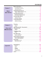
Contents
End-User License Agreement . . . . . . . . . . . . . . . . . . . . . . . . . . . . . . . . . . . . . . . . . . .
For Your Safety . . . . . . . . . . . . . . . . . . . . . . . . . . . . . . . . . . . . . . . . . . . . . . . . . . . . . . .
Chapter 1
Before You
Start
4
8
Cautions . . . . . . . . . . . . . . . . . . . . . . . . . . . . . . . . . . . . . . . . . . 12
Features . . . . . . . . . . . . . . . . . . . . . . . . . . . . . . . . . . . . . . . . . . 14
System Requirements . . . . . . . . . . . . . . . . . . . . . . . . . . . . . . 16
PC . . . . . . . . . . . . . . . . . . . . . . . . . . . . . . . . . . . . . . . . . . . . . . . . . . . . . .
Interface . . . . . . . . . . . . . . . . . . . . . . . . . . . . . . . . . . . . . . . . . . . . . . . . . .
16
16
Minimum Space Requirements . . . . . . . . . . . . . . . . . . . . . . . 17
Power Source . . . . . . . . . . . . . . . . . . . . . . . . . . . . . . . . . . . . . 17
Unpacking . . . . . . . . . . . . . . . . . . . . . . . . . . . . . . . . . . . . . . . . 18
Scanner Box . . . . . . . . . . . . . . . . . . . . . . . . . . . . . . . . . . . . . . . . . . . . . .
Printer Box . . . . . . . . . . . . . . . . . . . . . . . . . . . . . . . . . . . . . . . . . . . . . . . .
18
19
Part Names . . . . . . . . . . . . . . . . . . . . . . . . . . . . . . . . . . . . . . . 20
Scanner . . . . . . . . . . . . . . . . . . . . . . . . . . . . . . . . . . . . . . . . . . . . . . . . . .
Printer . . . . . . . . . . . . . . . . . . . . . . . . . . . . . . . . . . . . . . . . . . . . . . . . . . .
20
21
Scanner Panel Overview . . . . . . . . . . . . . . . . . . . . . . . . . . . . 22
Printer Panel Overview . . . . . . . . . . . . . . . . . . . . . . . . . . . . . . 24
Setting Up the Printer . . . . . . . . . . . . . . . . . . . . . . . . . . . . . . . 26
Chapter 2
Setup
Preparing the Imaging Unit . . . . . . . . . . . . . . . . . . . . . . . . . . . . . . . . . . .
Setting Up the Output Tray . . . . . . . . . . . . . . . . . . . . . . . . . . . . . . . . . . .
Installing the Toner Cartridges . . . . . . . . . . . . . . . . . . . . . . . . . . . . . . . . .
26
27
28
Setting Up the Scanner . . . . . . . . . . . . . . . . . . . . . . . . . . . . . 30
Unlocking the Scanner . . . . . . . . . . . . . . . . . . . . . . . . . . . . . . . . . . . . . . .
Installing the Automatic Document Feeder . . . . . . . . . . . . . . . . . . . . . . .
30
31
Installing the Scanner . . . . . . . . . . . . . . . . . . . . . . . . . . . . . . . 32
Loading Media . . . . . . . . . . . . . . . . . . . . . . . . . . . . . . . . . . . . . 34
Loading Paper or Transparencies in the Media Tray . . . . . . . . . . . . . . . .
Margins and Print Area . . . . . . . . . . . . . . . . . . . . . . . . . . . . . . . . . . . . . .
Loading Media in the Multi-purpose Tray . . . . . . . . . . . . . . . . . . . . . . . .
34
37
38
Connecting the System . . . . . . . . . . . . . . . . . . . . . . . . . . . . . 42
DCIS Standard System . . . . . . . . . . . . . . . . . . . . . . . . . . . . . . . . . . . . . .
DCIS Stand Alone System . . . . . . . . . . . . . . . . . . . . . . . . . . . . . . . . . . . .
Connecting the Scanner to a Computer . . . . . . . . . . . . . . . . . . . . . . . . .
Connecting the Printer to a Computer . . . . . . . . . . . . . . . . . . . . . . . . . . .
Setting the SCSI ID Number, Terminator . . . . . . . . . . . . . . . . . . . . . . . .
44
46
47
49
52
Power On . . . . . . . . . . . . . . . . . . . . . . . . . . . . . . . . . . . . . . . . . 53
Printing a Test Page From the Printer Panel . . . . . . . . . . . . 54
Installing the KX-PS8000 Software . . . . . . . . . . . . . . . . . . . . 55
Installing the Printer Driver and Utilities for Windows 3.1 . . . . . . . . . . . .
Installing the Printer Driver and Utilities for Windows 95 . . . . . . . . . . . . .
Installing the Printer Driver and Utilities for Windows NT 4.0 . . . . . . . . .
56
57
59
Removing the KX-PS8000 Software . . . . . . . . . . . . . . . . . . . 67
Installing the Bundled Software . . . . . . . . . . . . . . . . . . . . . . 68
Setting the Color Density . . . . . . . . . . . . . . . . . . . . . . . . . . . . 70
6
Contents
Before Operation . . . . . . . . . . . . . . . . . . . . . . . . . . . . . . . . . . . 75
Chapter 3
Basic
Operations
Acceptable Documents . . . . . . . . . . . . . . . . . . . . . . . . . . . . . . . . . . . . . .
Unacceptable Documents . . . . . . . . . . . . . . . . . . . . . . . . . . . . . . . . . . . .
Placing Documents . . . . . . . . . . . . . . . . . . . . . . . . . . . . . . . . . . . . . . . . .
75
75
76
Duplicating Documents . . . . . . . . . . . . . . . . . . . . . . . . . . . . . 77
Using the Digital Duplicator Utility . . . . . . . . . . . . . . . . . . . . . . . . . . . . . .
Using the Scanner Panel . . . . . . . . . . . . . . . . . . . . . . . . . . . . . . . . . . . . .
77
79
Scanning Documents . . . . . . . . . . . . . . . . . . . . . . . . . . . . . . . 80
Printing a Scanned Document . . . . . . . . . . . . . . . . . . . . . . . . . . . . . . . . .
Saving a Scanned Document . . . . . . . . . . . . . . . . . . . . . . . . . . . . . . . . .
82
83
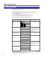
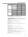
Scanner Menu Mode . . . . . . . . . . . . . . . . . . . . . . . . . . . . . . . . 84
Outline for Menus . . . . . . . . . . . . . . . . . . . . . . . . . . . . . . . . . . . . . . . . . .
Outline for Operation . . . . . . . . . . . . . . . . . . . . . . . . . . . . . . . . . . . . . . . .
85
87
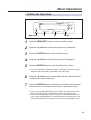
Printer Menu Mode . . . . . . . . . . . . . . . . . . . . . . . . . . . . . . . . . 88
Outline for Menus . . . . . . . . . . . . . . . . . . . . . . . . . . . . . . . . . . . . . . . . . .
Outline for Operation . . . . . . . . . . . . . . . . . . . . . . . . . . . . . . . . . . . . . . . .
89
91
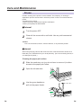
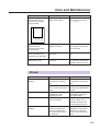
Cleaning . . . . . . . . . . . . . . . . . . . . . . . . . . . . . . . . . . . . . . . . . . 93
Chapter 4
Care and
Maintenance
Scanner . . . . . . . . . . . . . . . . . . . . . . . . . . . . . . . . . . . . . . . . . . . . . . . . . .
Printer . . . . . . . . . . . . . . . . . . . . . . . . . . . . . . . . . . . . . . . . . . . . . . . . . . .
93
94
User Replaceable Components . . . . . . . . . . . . . . . . . . . . . . . 98
Clearing a Jam . . . . . . . . . . . . . . . . . . . . . . . . . . . . . . . . . . . . 100
Scanner . . . . . . . . . . . . . . . . . . . . . . . . . . . . . . . . . . . . . . . . . . . . . . . . . . 100
Printer . . . . . . . . . . . . . . . . . . . . . . . . . . . . . . . . . . . . . . . . . . . . . . . . . . . 102
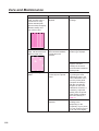
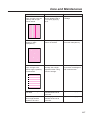
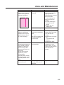
Troubleshooting . . . . . . . . . . . . . . . . . . . . . . . . . . . . . . . . . . . 114
Scanner . . . . . . . . . . . . . . . . . . . . . . . . . . . . . . . . . . . . . . . . . . . . . . . . . . 114
Printer . . . . . . . . . . . . . . . . . . . . . . . . . . . . . . . . . . . . . . . . . . . . . . . . . . . 115
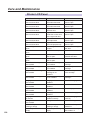
Error Messages . . . . . . . . . . . . . . . . . . . . . . . . . . . . . . . . . . . . 125
Scanner LCD Panel . . . . . . . . . . . . . . . . . . . . . . . . . . . . . . . . . . . . . . . . . 125
Printer LCD Panel . . . . . . . . . . . . . . . . . . . . . . . . . . . . . . . . . . . . . . . . . . 126
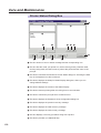
Status Display Program . . . . . . . . . . . . . . . . . . . . . . . . . . . . . 129
Scanner Status Dialog Box . . . . . . . . . . . . . . . . . . . . . . . . . . . . . . . . . . . 130
Printer Status Dialog Box . . . . . . . . . . . . . . . . . . . . . . . . . . . . . . . . . . . . . 132
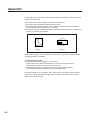
Repacking . . . . . . . . . . . . . . . . . . . . . . . . . . . . . . . . . . . . . . . . 134
Packing the Scanner . . . . . . . . . . . . . . . . . . . . . . . . . . . . . . . . . . . . . . . . 135
Packing the Printer . . . . . . . . . . . . . . . . . . . . . . . . . . . . . . . . . . . . . . . . . 137
Specifications . . . . . . . . . . . . . . . . . . . . . . . . . . . . . . . . . . . . . 145
Appendix
Scanner . . . . . . . . . . . . . . . . . . . . . . . . . . . . . . . . . . . . . . . . . . . . . . . . . .
Printer . . . . . . . . . . . . . . . . . . . . . . . . . . . . . . . . . . . . . . . . . . . . . . . . . . .
Media . . . . . . . . . . . . . . . . . . . . . . . . . . . . . . . . . . . . . . . . . . . . . . . . . . . .
Duplicate . . . . . . . . . . . . . . . . . . . . . . . . . . . . . . . . . . . . . . . . . . . . . . . . .
Software . . . . . . . . . . . . . . . . . . . . . . . . . . . . . . . . . . . . . . . . . . . . . . . . . .
SCSI Interface . . . . . . . . . . . . . . . . . . . . . . . . . . . . . . . . . . . . . . . . . . . . .
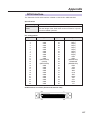
Parallel Interface . . . . . . . . . . . . . . . . . . . . . . . . . . . . . . . . . . . . . . . . . . .
145
147
150
155
156
157
158
Index . . . . . . . . . . . . . . . . . . . . . . . . . . . . . . . . . . . . . . . . . . . . . 159
7
For Your Safety
General
Warning
BTo prevent fire or shock hazard, do not expose this product to rain or any type of moisture.
Caution
BDo not open covers and do not attempt to repair the unit yourself. Refer servicing to qualified
personnel.
BAvoid contact with the rotating rollers when the ADF top cover is open.
Power Source
Warning
BThe power source voltage of this unit is listed on the nameplate. Only plug the unit into an outlet
with the proper voltage.
BWhen you operate this equipment, the outlet should be near the equipment and accessible.
BTo ensure safe operation the AC cord supplied must be inserted into standard three-prong AC
outlet which is effectively grounded (earthed) through the normal wiring.
BThe fact that the equipment operates satisfactorily does not imply that the power point is grounded
(earthed) and that the installation is completely safe. For your safety, if in any doubt about the
effective grounding (earthing) of the power point, consult a qualified electrician.
BIf the plug cannot be inserted into the AC outlet, contact a licensed electrician to replace the outlet
with a properly grounded (earthed) one. Do not defeat the purpose of the grounding (earthing) plug
(ex. do not use a conversion plug).
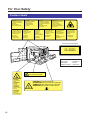
Laser Safety
Caution
BThe printer utilizes a laser.
Use of controls or adjustments or performance of procedures other than those specified herein
may result in hazardous radiation exposure.
Ozone Release
Warning
BMake sure that the printer is installed in a well ventilated room so as not to increase density of
ozone in the air. Since ozone is heavier than air, it is recommended that air at floor level be
ventilated.
8
For Your Safety
Light Source
Do not look directly at the light source lamps of the scanner as this may be harmful to your eyes.
Moving the Units
The scanner weighs approximately 17.3 kg {38.1 lbs.} and the printer weighs approximately 47.9 kg {105.5 lbs.}.
They must be handled by two people. Turn the power off and remove the power cords when handling the units.
9
For Your Safety
Caution Labels
DANGER:
Invisible laser radiation
when open and interlock
defeated.
AVOID DIRECT
EXPOSURE TO BEAM.
PELIGRO:
Cuando se abre y se
invalida el bloqueo, se
producen radiaciones
invisibles de láser.
EVÍTESE LA
EXPOSICIÓN
A TALES RAYOS.
CAUTION:
Invisible laser radiation
when open and
interlocks defeated.
AVOID EXPOSURE
TO BEAM.
VARNING:
Osynlig laserstrålning när denna
del är öppnad och
spärrar är
urkopplade.
STRÅLEN
ÄR FARLIG.
VORSICHT:
Unsichtbare Laserstrahlung,
wenn Abdeckung geöffnet
und Sicherheitsverriegelung
überbrückt.
NICHT DEM STRAHL
AUSSETZEN.
VARO!:
Näkymätöntä
avattaessa ja
suojalukitus
ohitettaessa olet
alttiina lasersäteilylle.
ÄLÄ KATSO
SÄTEESEEN.
ATTENTION:
Rayonnement laser invisible
dangereux en cas
d'ouverture et lorsque
la sécurité est neutralisée.
EXPOSITION DANGEREUSE
AU FAISCEAU.
VARNING:
Osynlig laserstrålning
när denna del är
öppnad och spärren är
urkopplad.
BETRAKTA EJ
STRÅLEN.
ADVARSEL:
Usynlig laserstråling
ved åbning når
sikkerhedsafbrydere
er ude af funktion.
UNDGÅ
UDSÆTTELSE FOR
STRÅLING.
ADVARSEL:
Usynlig laserstråling
når deksel åpnes og
sikkerhedslas brytes.
UNNGÅ
EKSPONERING
FOR STRÅLEN.
(220-240 VAC equipment)
CLASS 1 LASER PRODUCT
KLASSE 1 LASER PRODUKT
CLASSE 1 LASER PRODUIT
CLASE 1 LÁSER PRODUCTO
Laser diode properties
Laser output
: 5 mW max
Wavelength
: 780 nm
Emission duration : Continuous
CAUTION:
HOT SURFACE INSIDE
CAUTION:
HOT SURFACE
INSIDE
ATTENTION:
SURFACE
CHAUDE
CI-INTERIEUR
VORSICHT:
HEISSE FLÄCHE
INTERN
ATENCION:
SUPERFICIE
CALIENTE
EN EL INTERNO
10
CAUTION:HOT SURFACE BELOW
ATTENTION:SURFACE CHAUDE CI-DESSOUS
VORSICHT:HEIßE OBERFLÄCHE DARUNTER
ATENCION:SUPERFICIE CALIENTE ABAJO
For Your Safety
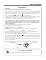
FOR USERS IN U.K.
IMPORTANT:
FOR YOUR SAFETY PLEASE READ THE FOLLOWING TEXT CAREFULLY
Both the printer and scanner are supplied with a moulded three pin mains plug each for your safety and
convenience. A 13 amp fuse is fitted in this plug. Should the fuse need to be replaced please ensure that
the replacement fuse has a rating of 13 amps and that it is approved by ASTA or BSI to BS 1362.
Check for the ASTA mark ASA or the BSI mark
on the body of the fuse.
If the plug contains a removable fuse cover you must ensure that it is refitted when the fuse is replaced.
If you lose the fuse cover the plug must not be used until a replacement cover is obtained.
A replacement fuse cover can be purchased from your local Panasonic Dealer.
IF THE FITTED MOULDED PLUG IS UNSUITABLE FOR THE SOCKET OUTLET IN YOUR HOME
THEN THE FUSE SHOULD BE REMOVED AND THE PLUG CUT OFF AND DISPOSED OF SAFELY.
THERE IS A DANGER OF SEVERE ELECTRICAL SHOCK IF THE CUT OFF PLUG IS INSERTED
INTO ANY 13 AMP SOCKET.
If a new plug is to be fitted please observe the wiring code as shown below.
If in any doubt please consult a qualified electrician.
WARNING: THIS APPLIANCE MUST BE EARTHED.
IMPORTANT: The wires in this mains lead are coloured in accordance with the following code.
Green-and-Yellow: Earth
Blue: Neutral
Brown: Live
As the colours of the wire in the mains lead of this appliance may not correspond with the coloured
markings identifying the terminals in your plug, proceed as follows.
The wire which is coloured GREEN-AND-YELLOW must be connected to the terminal in the plug which
is marked with the letter E or by the Earth symbol
, or coloured GREEN or GREEN-AND-YELLOW.
The wire which is coloured BLUE must be connected to the terminal in the plug which is marked with the
letter N or coloured BLACK.
The wire which is coloured BROWN must be connected to the terminal in the plug which is marked with
the letter L or coloured RED.
How to replace the fuse: Open the fuse compartment with a screwdriver and replace the fuse.
SCREWDRIVER
FUSE COVER
L
N
FUSE
FOR USERS IN AUSTRALIA
This mark shows that the product complies with AS/NZS 3548.
N52
11
Before You Start
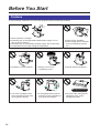
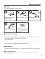
Cautions
To avoid machine malfunction, do not use the equipment under the following conditions:
BDirect exposure to sunlight
BExtremely high or low temperature [temperature range: 10˚C to
32.5˚C (50˚F to 90.5˚F)]
BExtremely high or low humidity (humidity range: 20% to 80% RH)
BCondensation due to rapid change of temperature
BUnstable or unlevel surfaces
BDirectly in front of air
conditioning vents
BAreas of poor ventilation
BAreas of high dust or chemical
fume concentration (solvent
etc.)
BLiquids near the equipment
Not genuine toner
BToo much media/document
which exceeds the limit mark
on the guide of the tray.
12
BFront/right/left doors opened
while the printer is operating; it
may cause a media jam.
BAny toner other than genuine
Panasonic toner; it may
damage the printer.
Before You Start
■CD-ROM
To prevent the CD-ROMs from accidental damages:
BDo not touch or write on the
surface of the disc.
BDo not leave the disc out of the
protective case.
BDo not place heavy objects on
the disc case or drop the case.
BTo clean the disc, hold the disc
by its edges and wipe it from
the center to the edges with a
dry, soft cloth.
BDo not leave the disc in direct
sunlight or near heat sources.
■Static Electricity Damage
To prevent static electricity damage to any of the following components, touch a grounded metal surface,
such as the printer’s bare metal frame prior to touching the component.
BThe interface connectors : SCSI, parallel and optional network
BADF interface connector
BElectrical components, connectors inside the printer and any components on the optional board (RAM
Expansion Board or Ethernet Card)
BThe connector pins on the optional 2nd cassette feeder for the printer
■Interface Cable
Always use a shielded interface cable. Use of an unshielded cable can result in radio interference with data.
■Waste Disposal Method
Waste material may be dumped or incinerated under conditions which meet all federal, state and local
environmental regulations.
13
Before You Start
Features
The KX-PS8000 is a high quality system that provides fast color image processing
functions, including color scanning, color printing, and color duplicating.
The KX-PS8000 is comprised of two components:
BColor scanner
(KX-PS8002)
BColor laser printer (KX-PS8001)
The KX-PS8000 system offers you the following functions:
BScanning
BPrinting
BDigital Duplicating
These functions are used for various tasks such as Desktop Publishing, or image
editing.
Notes:
BPositioning the scanner on top of the printer will conserve space.
BEach component can be used individually.
Scanner Function
■High quality
Resolution
Flatbed
ADF
Optical 600 dpi (dots per inch)
30 to 9600 dpi is software selectable.
60 to 2400 dpi is software selectable.
Color
Full-color mode:
Monochrome mode:
Maximum 16.7 million colors
Maximum 256 grayscale levels
■Image modification function
Image modification functions, such as density (gamma) adjustment, color
adjustment, and sharpening can be used to modify an image so that it meets your
requirements.
■High speed
When scanning an A4 size document:
An A4 size document can be scanned in 7.8 seconds at 300 dpi, and 15.7
seconds at 600 dpi. (Initial time is not included. Actual time depends on SCSI
interface and host computer.)
■Easy operation
Scanner driver
Easily scan full-color documents using a TWAIN-compliant application.
14
Before You Start
Printer Function
■High quality
Resolution
Maximum 1200 dpi *1
(*1 with SIMM options installed)
■High speed
Continuous printing on letter size paper
Full-color mode:
Maximum 3.5 ppm (pages per minute) for 4 Color (CMYK)
Maximum 4.7 ppm for 3 Color (CMY)*2
Monochrome mode: Maximum 14 ppm
(*2 only when using plain paper)
■Easy operation
Printer driver
Easily print full-color documents.
Digital Duplicator Function
■High quality
Resolution
Resolution is set according to the selected mode.
Standard mode: 300 x 300 dpi, 600 x 300 dpi
Fine*3 mode:
600 x 600 dpi
3
Enhanced* mode: 600 x 1200 dpi
(*3 with SIMM options installed)
■Image conversion function
Adjusts individual toner densities.
Scanned colors R (red), G (green), B (blue) are converted to printed colors
C (cyan), M (magenta), Y (yellow), K (black) automatically.
■High speed
Continuous full-color printing on letter size paper using ADF
4 Color (CMYK)
Standard mode:
Maximum 3.5 ppm (pages per minute)
4
Fine* mode:
Maximum 2.8 ppm
Enhanced*4 mode: Maximum 1.8 ppm
3 Color (CMY)*5
Maximum 4.7 ppm*4
Maximum 2.9 ppm
Maximum 2.4 ppm
(*4 with SIMM options installed)
(*5 only when using plain paper)
■Easy operation
Front Key Panel
Easily duplicate documents.
■Digital Duplicator Utility
Includes various editing operations, such as color adjustment,
enlargement/reduction, mirroring, and area duplicate.
15
Before You Start
System Requirements
PC
To operate the KX-PS8000 Enhanced system effectively, see the following.
CPU:
Operating System:
RAM:
Free disk space:
Virtual memory:
Display:
Drive:
More than Pentium or Pentium PRO
(133 MHz or faster CPU is recommended.)
Windows¨ 3.1*1, Windows 95*2 or Windows NT¨ 4.0*3 *4
(Intel only)
16 MB or more (More than 32 MB is recommended.)
100 MB or more
16 MB or more (More than 32 MB is recommended.)
for Windows 3.1/95
50 MB or more*5 (More than 100 MB is recommended.)
for Windows NT 4.0
Video card that can display more than 256 colors.
(A video card that can display more than 32,000 colors is
recommended.)
CD-ROM drive
*1 MicrosoftÒ WindowsÒ operating system Version 3.1 (hereafter Windows 3.1)
*2 MicrosoftÒ WindowsÒ 95 operating system (hereafter Windows 95)
*3 Microsoft¨ Windows NT¨ Workstation operating system, and Microsoft¨ Windows
NT¨ Server network operating system Version 4.0 (hereafter Windows NT 4.0)
*4 Service Pack 3 or later version is required.
*5 In the Virtual Memory window, change this setting in the Initial Size box.
Interface
One of the following can be used:
■SCSI interface requirements
SCSI cable
SCSI-2 (FAST SCSI) compatible ( ☞ P. 157)
SCSI-2 board
ASPI Manager compatible SCSI-2 board
(Adaptec AHA-2940 is recommended.)
ASPI manager
ASPI Manager is required.
(Refer to the SCSI-2 board manual.)
■Parallel interface requirement
Interface
16
Based on the IEEE P1284-C standard
(An ECP compatible parallel port is recommended
for Windows 95. To turn on the ECP mode, use the
computerÕs BIOS setup. Refer to the computerÕs
manual for details.)
Before You Start
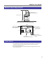
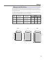
Minimum Space Requirements
50 cm (19.7″)
ADF opening space
105 cm (41.3″)*
* 126.5 cm (49.8″) with 2nd cassette feeder (option)
Rear
45 cm (17.7″)
Multi Purpose Tray
Opening Space
35 cm (13.8″)
Controller Board
Opening Space
Left
Right
60 cm (23.6″)
Front cover opening space
50 cm (19.7″)
Media tray Opening
Space
Power Source
BThe voltage level of the power source must not vary more than ±10% from the
voltage level marked on the nameplate (located on the back of the units).
BDo not use an extension cord.
BDo not use a line conditioner, transient suppressor or surge protector as it may
cause a machine error.
17
Before You Start
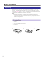
Unpacking
Make sure that all of the items shown below were provided and have not been
damaged. Report damage or shortages to the reseller from which the units were
purchased. Page 3 includes an area for recording important information such as the
name of reseller, serial numbers, and date of purchase.
Note:
BSave the original cartons and packing materials for future shipping and
transporting of the units. They have been specifically designed to protect the
equipment during shipment.
Scanner Box
1. Scanner
2. ADF (Automatic Document Feeder)
3. Power cord
1
18
2
3
Before You Start
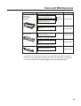
Printer Box
1. Printer
2. Toner cartridges (black, cyan, magenta, and yellow)
3. Power cord
4. SCSI cable (for connection between the scanner and the printer)
5. Guide pins (2)
6. KX-PS8000 Driver & Utility and Operating Manuals CD-ROM
7. Corel Photo-Paint 5 & 6 (CD-ROM)
8. TextBridge (OCR) CD-ROM
9. Color Calibration Card
10. Setup manual
1
2
4
7
3
5
6
8
9
10
19
Before You Start
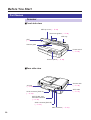
Part Names
Scanner
■Front side view
ADF top cover ( ☞ P. 93)
Document guides ( ☞ P. 76)
ADF tray
ADF
( ☞ P. 31, 76)
Scanner glass
Power switch
( ☞ P. 53)
Scanner panel ( ☞ P. 22)
■Rear side view
Scanner lock
( ☞ P. 30)
AC inlet
( ☞ P. 46, 48)
ADF cable
( ☞ P. 31)
SCSI connector [SCSI A]
( ☞ P. 44)
SCSI ID NO. and
terminator switches
( ☞ P. 52)
SCSI connector [SCSI B]
( ☞ P. 44)
ADF connector ( ☞ P. 31)
20
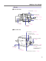
Before You Start
Printer
■Front side view
Printer panel ( ☞ P. 24)
Right side door
( ☞ P. 28, 111)
Output tray ( ☞ P. 27)
Media tray ( ☞ P. 34)
Front door
( ☞ P. 26)
Fuser
( ☞ P. 106)
Imaging unit
( ☞ P. 26)
■Rear side view
SCSI connector ( ☞ P. 44, 49)
SCSI ID NO. and
terminator switches ( ☞ P. 52)
Multi-purpose tray (MPT)
( ☞ P. 38)
Left side door ( ☞ P. 38)
[Media thickness switch*
( ☞ P. 38)]
Power switch
( ☞ P. 53)
AC inlet
( ☞ P. 46, 50)
* Accessible by opening
the left side door
Parallel interface connector ( ☞ P. 51)
21
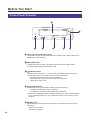
Before You Start
Scanner Panel Overview
$
#
%
RESET
INCREASE/NEXT
ENTER
STOP
START
B/W
START
COLOR
'
(
)
MODE
READY/ERROR
&
# LCD (Liquid Crystal Display) panel
The scanner LCD has two 20-character lines to display the scanner’s or
duplicator’s status/error messages or the duplicator’s menu settings. When
the duplicator is ready, “Ready” with duplicate settings such as number of
copy, density setting is displayed.
$ INCREASE/NEXT button
BWhen the scanner is ready, pressing this button increases the number of
duplicates by 1. You can set the number of duplicates from 1 to 99.
Pressing this button for more than 2 seconds automatically increases the
number of duplicates by 1.
Pressing this button for more than 8 seconds increases the number of
duplicates by 10.
BIn the Menu mode, pressing this button displays the next selection.
% MODE button
BWhen the scanner is ready, pressing this button enters the Menu mode.
BIn the Menu mode, pressing this button displays the next menu.
BPressing MODE + START COLOR, or MODE + START B/W allows you to
select an image type ( ☞ P. 79).
22
Before You Start
& READY/ERROR indicator
BThe READY indicator (green) blinks during initializing/scanning operation
and is illuminated (ON) when the scanner is ready.
BThe ERROR indicator (orange) blinks only when an error such as ADF jam
occurs and is illuminated (ON) when a system error occurs.
Status
READY Indicator
ERROR Indicator
Diagnosing/Initializing
Blinking *
OFF
Ready
ON
OFF
Scanning
Blinking *2
OFF
Scanning (for duplicate)
Blinking *3
OFF
Printing (for duplicate)
Blinking *
OFF
User Correctable Error
OFF
Blinking
Call for Service Error
OFF
ON
1
1
*1 Blinking with an interval of approximately 1.7 seconds
*2 Blinking with an interval of approximately 0.9 second
*3 Blinking with an interval of approximately 0.7 second
' STOP/RESET button
Pressing this button:
BExits the Menu mode.
BStops the duplicating process. (However, it does not stop immediately
because of data processing.)
BResets the scanner panel settings to the Menu Default setting (when
“Ready” is displayed). Refer to pages 85 and 86 for details on the Menu
Default setting.
( START B/W button
When a document is placed in the ADF tray or on the scanner glass, pressing
this button makes a black and white duplicate, regardless of the color of the
document.
) START COLOR/ENTER button
BWhen the scanner is ready and a document is placed in the ADF tray or on
the scanner glass, pressing this button makes a duplicate of the document.
If the original is a color document, a color duplicate is created.
BIn the Menu mode, after changing a selection, pressing this button activates
a selection. A “Y” appears to the left of the selection.
BThe printer is in the Energy Star mode when the scanner LCD shows
“Printer is Ready (Sleep)”. While the printer is in the Energy Star mode, a
document cannot be duplicated. To release the Energy Star mode, press the
START COLOR/ENTER button. When the printer is ready, “Ready” with
duplicate settings will appear on the LCD.
BTo resume printing after loading media or clearing a media jam, press this
button.
23
Before You Start
Printer Panel Overview
#
READY
)
ERORR
MENU
/EXIT
ENTER
CANCEL
$
%
CONTINUE
&
'
(
# LCD (Liquid Crystal Display) panel
The printer LCD has two 24-character lines to display the printer’s status/error
messages or menu settings.
$ MENU/EXIT button
BWhen the printer is ready, pressing this button enters the Menu mode.
BPressing this button exits the Menu mode.
% I /CANCEL button
BPressing this button for 2 or more seconds cancels the data in the printer.
BWhen the printer is in the Menu mode, pressing this button:
Displays the previous menu, item or selection.
Decreases the current numerical value of the selection.
Moves the cursor to left.
& F /CONTINUE button
BWhen the printer is in the Menu mode, pressing this button:
Displays the next menu, item or selection.
Increases the current numerical value of the selection.
BWhen error messages such as “Memory Overflow” or “SCSI Communication
Error” are displayed on the LCD, press this button to recover from an error
situation.
' ENTER button
This button is effective only when the printer is in the Menu mode. Pressing
this button:
Enters a sub - menu.
Activates a selection.
24
Before You Start
( ERROR indicator (orange)
BON: an internal error (Call for Service Error) has occurred.
BBlinking: user correctable error, such as media jam, open door, or a missing
replaceable component (e.g. Toner) has occurred.
) READY indicator (green)
BON: the printer is ready for operation.
BBlinking: the printer is warming up or in the Menu mode.
BBlinking fast: the printer is printing.
25
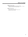
Setup
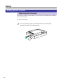
Setting Up the Printer
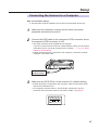
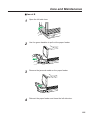
Preparing the Imaging Unit
26
1
Open the front door.
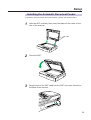
2
Turn the upper green lever clockwise until it stops and the arrows
are aligned. (This tightens the internal belts to ready the unit for
printing.)
3
Close the front door.
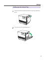
Setup
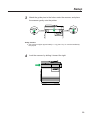
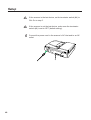
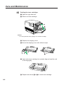
Setting Up the Output Tray
1
Remove the adhesive tape that holds the output tray against the
printer.
2
Lower the tray to the operating position.
27
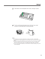
Setup
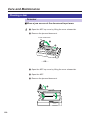
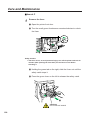
Installing the Toner Cartridges
Note:
BThe toner cartridges that are shipped with the printer are starter cartridges.
They are installed in exactly the same manner as the optional cartridges; the
only difference is that the starter cartridges have less toner. (The page life
expectancy is 3,000 pages, which is based on a 5% image area.)
1
Remove the packaging from the toner cartridge.
2
Remove the shipping cover from the cartridge.
Caution:
BTo avoid possible toner spillage, do not tilt cartridge.
Note:
BSave all packing material for shipping purposes.
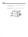
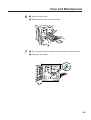
3
Open the right side door.
Caution:
BDo not leave the right side door open for more than 1 minute; the imaging unit
will be exposed to light and could be damaged.
28
Setup
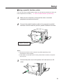
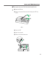
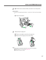
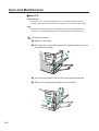
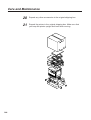
4
Insert the toner cartridge in the appropriately labeled slot.
5
Repeat steps 1, 2 and 4 for each toner cartridge.
6
Close the right side door.
From top to bottom, the order of the color toner cartridges is BLACK, CYAN,
MAGENTA, YELLOW.
When you have installed all the toner cartridges, go to step 6.
29
Setup
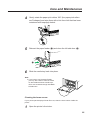
Setting Up the Scanner
Unlocking the Scanner
The scanner must be unlocked before it can be used. The scanner lock is located on
the left of the scanner.
To unlock the scanner:
1
Turn the scanner lock counterclockwise with a flat-blade
screwdriver until the lock pops out.
.........
.. .
..........
..
30
Setup
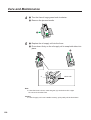
Installing the Automatic Document Feeder
To install the ADF (Automatic Document Feeder), perform the following steps.
1
Hold the ADF vertically, then insert the tabs into the holes on the
rear of the scanner.
Tabs
2
Close the ADF.
3
Plug the end of the ADF cable into the ADF connector located on
the back of the scanner.
31
Setup
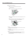
Installing the Scanner
The scanner can be installed using two methods:
Method A. On top of the printer
Method B. On left or right side of the printer
A
B
For method A, perform the following procedure.
32
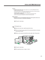
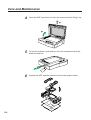
1
Remove the two top hole covers with a small flat-blade
screwdriver, then remove the two screws from the printer.
2
Install the guide pins and tighten them with a flat-blade
screwdriver.
Setup
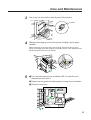
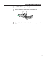
3
Match the guide pins to the holes under the scanner, and place
the scanner gently onto the printer.
Safety Caution:
BThe scanner weighs approximately 17.3 kg {38.1 lbs.}. It must be handled by
two people.
4
Lock the scanner by sliding it toward the right.
33
Setup
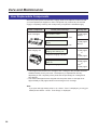
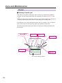
Loading Media
Loading Paper or Transparencies in the Media
Tray
The printer uses five different trays:
Tray
Size
A4 Paper
210 mm x 297 mm (8.3″ x 11.7″)
A4 Transparency
210 mm x 297 mm (8.3″ x 11.7″)
Letter Paper
216 mm x 279 mm (8.5″ x 11″)
Letter Transparency
216 mm x 279 mm (8.5″ x 11″)
Legal Paper
216 mm x 356 mm (8.5″ x 14″)
Notes:
BMake sure that you load the correct media. Each tray is designed and labeled
for only paper or transparency. If you load the incorrect media type in a tray, it
may cause a jam.
BIf you have the 2nd Cassette Feeder installed:
— If you wish to use the automatic cassette-switching feature (a large print job,
for example), make sure that all trays in the printer are the same media type
and size.
— The transparency tray should be inserted in the upper or middle tray slots.
The printer is shipped with a media tray (either Letter paper or A4 paper) installed.
34
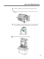
1
Pull the media tray out of the printer.
2
Remove all packaging materials from inside the media tray; refer
to the instruction sheet attached to the tray.
Setup
3
Push down on the metal plate until it clicks, locking it in place.
4
Fan the media (paper/transparencies), then tap it on a level
surface to avoid media jams or skewed printing.
Notes:
BTo optimize your printer’s performance, always use clean, unused media.
BBe careful not to leave fingerprints on the media, which can result in a smudged
print.
BReusing media that has been fed through the printer once (for example, after
jams) can reduce the life of the consumables and paper path components.
BThe recommended transparency is 3M CG3700. If the print quality is poor, print
on the other side.
35
Setup
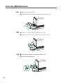
5
Place the media in the tray under the hooks.
The height of media should not exceed the limit mark on the tray, or it may
cause a jam.
Notes:
BLoad media with the print side down. Most media has instructions
recommending the side to be printed first.
BDo not mix different types or thicknesses of media in the media tray at one time;
this may cause a jam.
6
36
Slide the media tray completely into the slot.
Setup
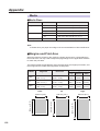
Margins and Print Area
When the image is printed on the media, the image (print area) is a bit smaller than
the media size. You may need to adjust the page margins in the application software
to match the print area.
The following table and illustrations show the page sizes, the largest print areas, and
the margins for the media sizes supported on this printer.
Page size
Print area
Letter
216 mm x 279 mm
(8.5″ x 11″)
A4
Legal
Top
Bottom
Sides
208 mm x 269 mm
(8.2″ x 10.6″)
5.6 mm
(0.22″)
5.6 mm
(0.22″)
3.6 mm
(0.14″)
210 mm x 297 mm
(8.3″ x 11.7″)
200 mm x 287 mm
(7.9″ x 11.3″)
5.1 mm
(0.2″)
4.7 mm
(0.19″)
4.7 mm
(0.19″)
216 mm x 356 mm
(8.5″ x 14″)
208 mm x 343 mm
(8.2″ x 13.5″)
5.8 mm
(0.23″)
5.8 mm
(0.23″)
3.6 mm
(0.14″)
Letter
A4
Legal
200 mm (7.9″)
287 mm (11.3″)
208 mm (8.2″)
269 mm (10.6″)
Margins
208 mm (8.2″)
343 mm (13.5″)
Media
37
Setup
Loading Media in the Multi-purpose Tray
The multi-purpose tray (MPT) serves as an additional tray for loading any type of
media that ranges in size from 91 mm x 254 mm to 216 mm x 356 mm (3.6² x 10² to
8.5² x 14²). Use it to load a single sheet or a stack of media. The amount of media
you can load depends upon its thickness.
Use the multi-purpose tray to accomplish the following:
Print on standard and special media
BStandard media
¾ Laser paper [75 to 165 g/m2 (20 to 44 lbs.)]
BSpecial media
¾ Labels
¾ Envelope (#10 or larger size)* [Black Text only]
¾ Transparency (The print quality may not be stable. Use the media tray for
best reliability.)
¾ Coated paper
* If the Envelope is larger than #10, you must select a paper size that is larger than
your envelope ( ☞ P. 124, P. 126, P. 133 of the Utilities and Drivers Reference
Guide).
Two-sided printing (double-sided) on laser paper
You should not expect the same print quality and reliability that you get with onesided printing. For details, refer to page 151.
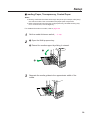
Setting media thickness switch
Because the printer accommodates various media weights from the multi-purpose
tray, media thickness can be manually selected for the most reliable paper-picking.
Follow these steps:
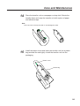
1
Open the left side door (#). The green media thickness switch is
located on the paper feeder and has three settings:
#
Thin
2
38
Thick
Move the switch to the desired setting.
Switch setting
3
Middle
Media
Thin (Default)
Laser paper 75 to 90 g/m2 (20 to 24 lbs.)
Middle
Laser paper 91 to 123 g/m2 (25 to 32 lbs.),
Transparency, Label, Coated paper
Thick
Laser paper 124 to 165 g/m2 (33 to 44 lbs.)
Envelope
Close the left side door.
Setup
■Loading Paper, Transparency, Coated Paper
Notes:
BReusing media that has been fed through the printer (for example, after jams)
can reduce the life of the consumables and paper path components.
BWhen printing legal size using the multi-purpose tray, backside marking may
occur. If this occurs, use the legal tray.
For detailed information on media, refer to page 150.
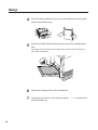
1
Set the media thickness switch ( ☞ P. 38).
2
# Open the Multi-purpose tray.
$ Extend the media support by sliding it outward.
#
$
3
Separate the media guides to the approximate width of the
media.
39
Setup
4
Fan the media, and then tap it on a level surface to avoid media
jams or skewed printing.
5
Insert the media with the printing side up into the multi-purpose
tray.
The height of media should not exceed the limit mark on the left guide, or it
may cause a media jam.
40
6
Adjust the media guides to the media size.
7
Use the printer driver or the scanner panel ( ☞ P. 84) to select the
multi-purpose tray.
Setup
■Loading an Envelope
Do not insert more than one envelope at a time. Only black text can be printed
on envelopes. For more detailed information on envelopes, refer to page 153.
Note:
BThe envelope may be creased when printed.
1
Set the media thickness switch ( ☞ P. 38).
2
Adjust the media guides to the width of the envelope.
3
Insert the envelope with the short end entering the printer first
and the printing side facing up. The edge where the stamp is
located enters the printer last.
4
Use the printer driver to select Envelope in the Paper size menu
and the Paper source menu.
■Loading Labels
For detailed information on labels, refer to page 152.
1
Set the media thickness switch ( ☞ P. 38).
2
Adjust the media guides to the width of the label sheets.
3
Insert the label sheets in the multi-purpose tray with the printing
side up and the top of the sheets enter first.
The height of labels should not exceed the limit mark on the guide.
4
Use the printer driver or the scanner panel ( ☞ P. 84) to select
Label.
41
Setup
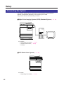
Connecting the System
The scanner, printer, and PC (with SCSI-2 board installed) can be installed in
different configurations depending on the function(s) to be used.
Only one PC can be connected with your DCIS.
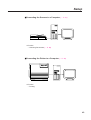
■Digital Color Imaging System (DCIS) Standard System ( ☞ P. 44)
BFunctions
Duplicating Documents ( ☞ P. 77)
Scanning Documents ( ☞ P. 80)
Printing
■DCIS Stand Alone System ( ☞ P. 46)
BFunction
Duplicating Documents ( ☞ P. 77)
42
Setup
■Connecting the Scanner to a Computer ( ☞ P. 47)
BFunction
Scanning Documents ( ☞ P. 80)
■Connecting the Printer to a Computer ( ☞ P. 49)
BFunction
Printing
43
Setup
DCIS Standard System
If a SCSI-2 board has been installed in your computer, be sure it is compatible
( ☞ P. 157 “SCSI Interface” specifications). If it is not installed, be sure to install only a
recommended SCSI-2 board ( ☞ P. 16).
Recommendation for connecting DCIS:
BWe recommend you to connect your DCIS with only one SCSI device.
BFor a SCSI chain with up to three SCSI-2 (FAST SCSI) devices connected, the
total length of the SCSI cables must be less than 3 m (9.8 ft.).
BUse shielded cables for SCSI-2 (FAST SCSI).
Note:
BAlthough a SCSI chain may exceed the recommended length and still operate
we cannot guarantee this operation.
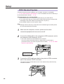
1
Make sure the computer, scanner, printer and the other
connected peripheral devices are turned off.
2
Connect the SCSI cable to the computer’s SCSI connector and to
the scanner’s SCSI connector A or B.
BThe SCSI-2 board must be installed in the computer.
If you do not have a SCSI-2 board or a SCSI cable, you will need to
purchase one from your local computer store or dealer ( ☞ P. 16, 157 “SCSI
Interface” specifications).
Computer’s
SCSI connector
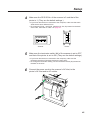
3
Connect the SCSI cable provided to the printer’s SCSI connector
and to the scanner’s SCSI connector.
The printer must be the last device in the chain because the printer has only
one SCSI connector.
44
Setup
4
Make sure the SCSI ID No. of the scanner is 2 and that of the
printer is 1. (They are the default settings.)
BIf you have other devices connected to the computer, make sure that each
SCSI device has a different ID No.
BTo change an ID No., use ID No. switches (#1, #2, #3) located on the back
of the units. Also refer to Table 1 on page 52.
1
ON
2
2
3
4
3
1
4
ON
Scanner
5
Printer
Make sure the terminator switch (#4) of the scanner is set to OFF
and that of the printer is set to ON. (They are the default settings.)
BIf you have other devices connected to the computer, make sure the
terminator switches of all those devices are set to OFF.
BTo change the terminator setting, use the terminator switch (#4) located on
the back of the units.
6
Connect the power cords to the scanner’s AC inlet, to the
printer’s AC inlet and to AC outlets.
45
Setup
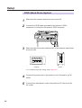
DCIS Stand Alone System
1
Make sure the scanner and printer are turned off.
2
Connect the SCSI cable provided to the scanner’s SCSI
connector A or B and to the printer’s SCSI connector.
3
Make sure the terminator switches (#4) of the scanner and printer
are set to ON.
1
ON
2
2
3
4
3
1
4
ON
Scanner
Printer
BTo change a terminator setting, refer to page 52.
46
4
Connect the power cord to the scanner’s AC inlet and to an AC
outlet.
5
Connect the other power cord to the printer’s AC inlet and to an
AC outlet.
Setup
Connecting the Scanner to a Computer
Note for Terminator setting:
BThe terminator must be installed or set to ON on the last SCSI device only.
1
Make sure the computer, scanner and the other connected
peripheral devices are turned off.
2
Connect the SCSI cable to the computer’s SCSI connector and to
the scanner’s SCSI connector A or B.
BThe SCSI-2 board must be installed in the computer.
If you do not have a SCSI-2 board or a SCSI interface cable, you will need to
purchase one from your local computer store or dealer ( ☞ P. 16, 157 “SCSI
Interface” specifications).
BIf other SCSI devices are connected to the computer, connect the scanner
anywhere in the SCSI chain.
Computer’s
SCSI connector
3
Make sure the SCSI ID No. of the scanner is 2 (default setting).
BIf other devices are connected to the computer, make sure that each SCSI
device has a different ID No.
BTo change the scanner’s ID No., use the ID No. switches (#1, #2, #3)
located on the back of the scanner. Also refer to Table 1 on page 52.
1
2
3
4
ON
47
Setup
4A
If the scanner is the last device, set its terminator switch (#4) to
ON. Go to step 5.
4B
If the scanner is not the last device, make sure the terminator
switch (#4) is set to OFF (default setting).
5
48
Connect the power cord to the scanner’s AC inlet and to an AC
outlet.
Setup
Connecting the Printer to a Computer
Note for Terminator setting:
BThe printer must be the last device in the chain. The terminator setting of all
other devices in the chain must be off.
■Using a SCSI cable:
1
Make sure the computer, printer and the other connected
peripheral devices are turned off.
2
Connect the SCSI cable to the computer’s SCSI connector and
the printer’s SCSI connector.
BA SCSI-2 board must be installed in the computer.
If you do not have a SCSI-2 board or a SCSI interface cable, you will need to
purchase one from your local computer store or dealer ( ☞ P. 16, 157 “SCSI
Interface” specifications).
Computer’s
SCSI connector
3
Make sure the SCSI ID No. of the printer is 1 (default setting).
BIf you have other devices connected to the computer, make sure that each
SCSI device has different ID No.
BTo change the printer’s ID No., use the ID No. switches (#1, #2, #3) located
on the back of the printer. Also refer to Table 1 on page 52.
1
ON
2
3
4
49
Setup
50
4
Make sure the terminator switch (#4) of the printer is set to ON
(default setting).
5
Connect the power cord to the printer’s AC inlet and to an AC
outlet.
Setup
■Using a parallel interface cable:
If you do not have a parallel interface cable, you will need to purchase one from your
local computer store or dealer ( ☞ P. 158 for “Parallel Interface” specifications).
1
Make sure the computer, printer and the other connected
peripheral devices are turned off.
2
Connect the parallel interface cable to the computer’s parallel
interface connector and the printer’s parallel interface connector.
Computer’s parallel
interface connector
Notes:
BThe actual connector on the computer may differ depending on the
manufacturer of the computer.
BIf the cable is connected to the PC via a printer buffer or selector, the printer
may not print.
3
Connect the power cord to the printer’s AC inlet and to an AC
outlet.
51
Setup
Setting the SCSI ID Number, Terminator
■Setting the SCSI ID Number
In most cases, there is no need to change the default settings.
However, if you have other peripheral devices connected in a SCSI chain, check if
their ID numbers conflict with that of the printer or scanner. Be sure to choose an
unassigned ID number.
ID number can be changed by using the SCSI ID No. switches (#1, #2, #3) [ ☞ Table
1 below].
Table 1
ID No.
SCSI ID No. switches
#1
#2
#3
0
OFF
OFF
OFF
1
ON
OFF
OFF
2
OFF
ON
OFF
3
ON
ON
OFF
4
OFF
OFF
ON
5
ON
OFF
ON
6
OFF
ON
ON
7
ON
ON
ON
SCSI ID No. switches
1
2
3
4
ON
Terminator switch
■Setting the Terminator
The terminator setting can be changed by using the terminator switch (#4).
Terminator
ON:
1
2
3
4
3
4
ON
Terminator
OFF:
1
ON
52
2
Setup
Power On
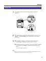
1
Turn ON the scanner, then the printer. Next turn ON the
computer.
2
The scanner will be ready after approximately 20 seconds, and
“Ready”, “PTR Initializing” will be displayed on the scanner
LCD panel.
3
# The READY indicator on the printer starts flashing and
“Initializing” is displayed on the printer LCD panel.
$ After approximately 3.5 minutes, the printer’s READY indicator
is illuminated and “Ready” is displayed on the printer LCD
panel.
The printer is ready for printing.
Note:
BWhen you power on your system for the first time, if “New Hardware Found” is
displayed on the computer screen, refer to page 58.
53
Setup
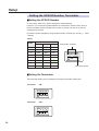
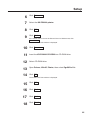
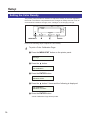
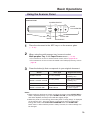
Printing a Test Page From the Printer Panel
The test page provides general information on printer settings and configuration.
Make sure the printer is ready and paper is loaded. Use the following procedure to
print a test page:
1
Press the MENU/EXIT button to enter the Menu Mode.
Menu Mode
Test Page
2
Press the ENTER button.
Test Page
Configuration Page
3
Press the ENTER button again.
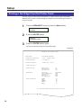
The printer will start printing a configuration page.
(Example)
Panasonic Color Laser Printer
Model Name
: KX-PS8000 Enhanced
Printer Rom Version No.
: V043 :
Installed Memory
: 016 MBytes
Installed Cassette
: Media Tray - Letter
M8C160 (R019)
< Panel Settings >
System Setting
Energy Star
Auto Continue
Data Time Out
on
off
off
Maintenance
Page Count
Color Imaging Unit
Transfer Unit
Fuser Unit
Oil Supply Roll
0000000000
000%
000%
000%
000%
Color Calibration
OFFSET
CYAN
MAGENTA
YELLOW
BLACK
00
00
00
00
00
(C) 1996-1998 Kyushu Matsushita Electric Co.,Ltd.
54
Setup
Installing the KX-PS8000 Software
The KX-PS8000 software installation will create the following.
BPrinter driver for Windows 3.1, Windows 95 or Windows NT 4.0
BTWAIN scanner driver (32 bit and/or 16 bit)
BDigital Duplicator Utility
BStatus Display for Windows 3.1, Windows 95 or Windows NT 4.0
Notes:
BIf you are using Windows 3.1, disable or uninstall any application software’s
printer status to prevent conflicts with the KX-PS8000 Status Display for
Windows 3.1.
BWhen reinstalling the KX-PS8000 software, do it immediately after restarting
Windows.
To install the bundled software (Corel Photo-Paint, TextBridge, or Panasonic font
manager), refer to page 68 “Installing the Bundled Software”.
55
Setup
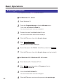
Installing the Printer Driver and Utilities for
Windows 3.1
56
1
Start Windows 3.1.
2
Quit all applications.
3
Insert the KX-PS8000 CD-ROM into your computerÕs CD-ROM
drive.
4
Click File from the Program Manager, then click Run... .
5
Click Browse and select your CD-ROM drive from the [Drives:]
box.
6
Select Setup.exe, and click OK .
7
Click OK .
8
Follow the instructions on the screen to complete the installation.
The Installer starts.
Setup
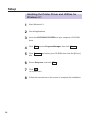
Installing the Printer Driver and Utilities for
Windows 95
1
Start Windows 95.
2
Quit all applications.
3
Click Start , move the pointer to Settings, then click
Control Panel.
The Control Panel window is displayed.
4
Double click Add/Remove Programs .
5
Click Install .
6
Insert the KX-PS8000 CD-ROM into CD-ROM drive.
7
Click Next> .
8
Click Finish .
9
Follow the instructions on the screen to complete the installation.
The Add/Remove Program Properties window is displayed.
The Install Program From Floppy Disk or CD-ROM window is displayed.
The Run Installation Program window is displayed.
Wait until the Panasonic KX-PS8000 Utilities Welcome window is displayed.
After installation, restart your system.
Note:
BDuring installation, when ÒSetup is adding icon to the Printer folder. Please wait
several minutesÓ is displayed, the processing may take approximately 5 to 10
minutes to complete depending on the system.
57
Setup
■Using Plug and Play
1
Turn on the scanner, then the printer.
2
Turn on the computer and start Windows 95.
3
Insert the KX-PS8000 CD-ROM into CD-ROM drive.
4
Click Next> .
5
Click Finish .
The New Hardware Found window is displayed for a few seconds, then the
Update Device Driver Wizard window is displayed.
The Insert Disk window is displayed.
6
Click OK .
7
Type in your CD-ROM drive name followed by :\ (example; D:\) in
the Copy file from field and click OK .
The Copying Files window is displayed.
Wait until the Panasonic KX-PS8000 Utilities Welcome window is displayed.
8
Follow the instructions on the screen to complete the installation.
After installation, restart your system.
Note:
BThe Plug and Play installation procedure varies depending on the version of
Windows 95. Refer to Help in Windows 95.
58
Setup
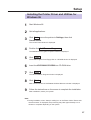
Installing the Printer Driver and Utilities for
Windows NT 4.0
1
Start Windows NT 4.0.
2
Quit all applications.
3
Click Start , move the pointer to Settings, then click
Control Panel.
The Control Panel window is displayed.
4
Double click Add/Remove Programs .
5
Click Install .
6
Insert the KX-PS8000 CD-ROM into CD-ROM drive.
7
Click Next> .
8
Click Finish .
9
Click Next> .
10
The Add/Remove Program Properties window is displayed.
The Install Program From Floppy Disk or CD-ROM window is displayed.
The Run Installation Program window is displayed.
Wait until the Panasonic KX-PS8000 Utilities Welcome window is displayed.
The Setup Type window is displayed.
Click the type of setup, then click Next> .
The Select Program Folder window is displayed.
59
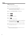
Setup
11
Click Next> .
12
Click Next> .
13
Click Next> .
14
Select LPT port by clicking on the check box.
15
Click Next> .
16
Click Have Disk... .
The Start Copying Files window is displayed.
After copying files, the Add Printer Wizard window is displayed.
The Install From Disk window is displayed.
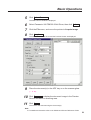
17
Click Browse... .
18
Click Cancel .
19
Select CD-ROM drive.
20
Open Drivers, Winnt40, Printer, then select pgdint.inf file.
21
Click Open .
22
Follow the instructions on the screen to complete the installation.
The Locate File window is displayed.
To connect the printer to a SCSI port, install the SCSI port.
Refer to the Ports tab of the Panasonic KX-PS8000 Properties window
(☞ P. 131 to P. 135 of the Utilities and Drivers Reference Guide).
60
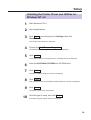
Setup
Installing the SCSI port:
Notes:
BIt is recommended that you do not connect the printer directly to the file server.
Otherwise the printer and server performance may be diminished.
BWhen printing through the SCSI port, the access speed between other
connected SCSI devices is diminished.
BTo connect the KX-PS8000 to your SCSI port, a SCSI driver and ASPI Manager
must be installed. Refer to your SCSI board manual.
1
Click Start , select Settings, then click Printers.
2
Click the Panasonic KX-PS8000 icon.
3
Click the File menu, then click Properties.
The Printers window is displayed.
The Panasonic KX-PS8000 Properties window is displayed.
4
Click the Ports tab.
5
Click Add Port... .
6
Click New Monitor... .
7
Insert the KX-PS8000 CD-ROM into CD-ROM drive.
8
Click Browse... .
9
Click Cancel .
The Printer Ports window is displayed.
The Installing Print Monitor window is displayed.
The Locate File window is displayed.
Note:
BThe SCSI port cannot be installed through the Monitor.inf file when copied to a
directory with long file name.
61
Setup
10
Select CD-ROM drive.
11
Open Drivers, WinNT40, Printer, then select Monitor.inf file.
Click Open .
The Installing Print Monitor is displayed.
12
Click OK .
13
Click New Port.... .
The Printer Ports window is displayed.
The Port Name window is displayed.
14
Type the port name (for example; KXPS8000GDI), then click
OK .
The Printer Ports window is displayed.
15
62
Click Close .
Setup
■Using the Printer in a Network Environment
For the server computer:
To share the printer with other clients on the network, perform the following steps
after installing the printer driver.
1
Double click the My computer icon.
2
Double click the Printers icon.
3
Select the Panasonic KX-PS8000 printer.
4
Click File menu, then click Sharing....
5
Click Shared.
6
Enter the printer name
(ex. KX-PS8000).
If the shared printer is used through Windows 95, the printer name must not
exceed 12 characters.
7
Click OK .
63
Setup
For a client computer:
To use the printer connected to the server, perform the following steps after installing
the printer driver.
<For Windows NT 4.0 Users>
1
Click Start , select Settings, then click Printers.
2
Double click the Add Printer icon from Printers.
3
Select Network printer server.
4
Click Next> .
5
Select the Panasonic KX-PS8000 printer in the Shared
Printers box.
6
Click OK and follow the instructions on the screen.
7
Click Finish .
The Printers window is displayed.
<For Windows 95 Users>
64
1
Double click the My computer icon.
2
Double click the Printers icon.
3
Double click the Add Printer icon.
4
Click Next> .
5
Click Network printer, then click Next> .
Setup
6
Click Browse... .
7
Select the KX-PS8000 printer.
8
Click OK .
9
Click Next> .
If the server does not have the Printer Driver for Windows 95, click
Have Disk... .
The Install From Disk window is displayed.
10
Click Browse... .
11
Insert the KX-PS8000 CD-ROM into CD-ROM drive.
12
Select CD-ROM drive.
13
Open Drivers, Win95, Printer, then select Pgdi95.inf file.
14
Click OK .
15
Click OK .
16
Click Next> .
17
Click Next> .
18
Click Finish .
The Install From Disk window is displayed.
65
Setup
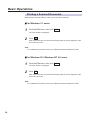
■Removing the Printer Driver
66
1
Click Start , move the pointer to Settings and click Printers.
2
Select Panasonic KX-PS8000.
3
Click File menu, then click Delete.
4
Click Yes .
Setup
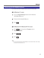
Removing the KX-PS8000 Software
If you need to remove the KX-PS8000 software, perform the following steps.
■For Windows 3.1 users:
1
From the Program Manager double click the Panasonic
KX-PS8000 Utilities icon.
2
Double click the Uninstall Utility icon.
3
Click Yes .
■For Windows 95 / Windows NT 4.0 users:
1
Click Start , move the pointer to Programs, then to
KX-PS8000 Utilities.
2
Click Uninstall .
3
Click Yes .
Note:
BFor removing the Panasonic KX-PS8000 icon in the Printer Folder, refer to Help
in Windows 95 / Windows NT 4.0.
67
Setup
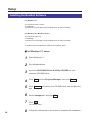
Installing the Bundled Software
For Windows 3.1:
BCorel Photo-Paint 5.0 Plus
BTextBridge
BPanasonic font manager (in KX-PS8000 Driver & Utility CD-ROM)
For Windows 95 / Windows NT 4.0:
BCorel Photo-Paint 6.0
BTextBridge
BPanasonic font manager (in KX-PS8000 Driver & Utility CD-ROM)
To install the above applications, perform the following steps.
■For Windows 3.1 users:
68
1
Start Windows 3.1.
2
Quit all applications.
3
Insert the KX-PS8000 Driver & Utility CD-ROM into your
computer CD-ROM drive.
4
Click File from the Program Manager, then click Run... .
5
Click Browse and select your CD-ROM drive from the [Drives:]
box.
6
Select Instapp.exe, and click OK .
7
Click OK .
8
Follow the instructions on the screen to complete the installation.
The installer starts.
Setup
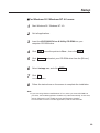
■For Windows 95 / Windows NT 4.0 users:
1
Start Windows 95 / Windows NT 4.0.
2
Quit all applications.
3
Insert the KX-PS8000 Driver & Utility CD-ROM into your
computer CD-ROM drive.
4
Click Start , move the pointer to Run..., then click Run .
5
Click Browse and select your CD-ROM drive from the [Drives:]
box.
6
Select Instapp.exe, and click OPEN .
7
Click OK .
8
The installer starts.
Follow the instructions on the screen to complete the installation.
Note:
BIf you are using Windows 95/Windows NT 4.0, when you insert CD-ROM into
your drive, the bundled application installer may start automatically. In this case,
quit the Panasonic quick installer and use the application installer.
For information on how to use the applications, refer to their manuals.
69
Setup
Setting the Color Density
The printer panel provides an interface to adjust the density of the toner applied to
the media. This feature compensates for the changes in density that can occur as
environmental conditions change, toner cartridges or the imaging unit age.
READY
ERORR
MENU
/EXIT
ENTER
CANCEL
MENU/EXIT
I
CONTINUE
F
ENTER
Perform the following steps to adjust the color density:
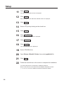
1
To print a Color Calibration Page:
# Press the MENU/EXIT button on the printer panel.
Menu Mode
Test Page
$ Press the F button.
Menu Mode
Color Calibration
% Press the ENTER button.
Color Calibration
Calibration Offset
& Press the F button 5 times and the following is displayed.
Color Calibration
Calibration Test Print
' Press the ENTER button.
A Color Calibration Page will be printed.
70
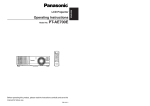
Setup
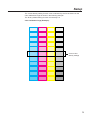
The current density setting for each color is indicated by the line enclosure on the
Color Calibration Page as shown in the following example.
The factory default setting for each color density is 0.
Color Calibration Page (Example):
Current color
density settings
71
Setup
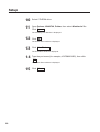
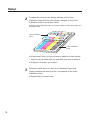
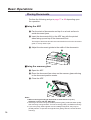
2
Compare the current color density settings on the Color
Calibration Page with the color density samples on the Color
Calibration Card to see if they match.
Place the Color Calibration Page on at least 2 sheets of clean white paper in a
well-lighted area.
Color Calibration
Card
Color Calibration
Page
BIf they match, then you do not need to adjust the color density
and you may proceed with any operation you wish to perform.
BIf they do not match, go to step 3.
3
Determine which block on the Color Calibration Page most
closely matches the density of the cyan sample on the Color
Calibration Card.
BRepeat step 3 for each color.
72
Setup
4A
If you wish to adjust the density for all colors simultaneously,
perform the following, then go to step 5.
# Repeat instructions # through % of step 1 on page 70.
Color Calibration
Calibration Offset
$ Press the ENTER button.
Calibration Offset
0* (-5 to 5)
% Press the F/I button to darken/lighten all the colors.
Pressing the F/I button twice selects the next/previous level settings.
(For example:)
BIf you wish to make the density setting darker by 2 levels:
Press the F button 4 times.
BIf you wish to make the density setting lighter by 1 level:
Press the I button 2 times.
& Press the ENTER button.
Color Calibration
CYAN
' Press the F button 4 times and the following is displayed.
Color Calibration
Calibration Test Print
73
Setup
4B
If you wish to adjust the density for each color independently,
perform the following, then go to step 5.
# Repeat instructions # through % of step 1 on page 70.
$ Press the F button.
Color Calibration
CYAN
% Press the ENTER button.
CYAN
0* (-10 to 10)
& Press the F/I button to darken/lighten the cyan color.
Pressing the F/I button twice selects the next/previous level setting.
(For example:)
BIf you wish to make the density setting darker by 4 levels:
Press the F button 8 times.
BIf you wish to make the density setting lighter by 2 levels:
Press the I button 4 times.
' Press the ENTER button.
Color Calibration
MAGENTA
( Repeat instructions % through ' for each color
(MAGENTA, YELLOW, BLACK).
BTo skip a color, press the F button.
BTo return to a previous color, press the I button.
BBefore going to step 5, make sure the following is displayed.
Color Calibration
Calibration Test Print
5
Press the ENTER button to reprint the Color Calibration Page.
BThe line enclosure reflects the changes made to the settings.
BIf you are not satisfied with the current color density settings, repeat steps 4
and 5 above.
Notes:
BThe color density setting affects the average life of toner.
BSave the Color Calibration Card for future calibrations.
74
Basic Operations
Before Operation
Acceptable Documents
The documents that meet the following conditions can be scanned.
For scanner glass:
Max. 216 mm x 356 mm (8.5″ x 14″)
For ADF (Automatic Document Feeder):
Document width: 100 mm to 216 mm (3.94″ to 8.5″)
Document length: 178 mm to 356 mm (7″ to 14″)
ADF tray: up to 50 pages of document [75 g/m2 (20 lbs.) fresh paper]
Document weight: 52.5 g/m2 to 127.5 g/m2 (14 lbs. to 34 lbs.)
Unacceptable Documents
Do not use the following types of documents.
For scanner glass:
Document on which ink, paste or correction fluid has not completely dried
Heavily curled or creased paper
For ADF (Automatic Document Feeder):
Document on which ink, paste or correction fluid has not completely dried
Do not use the following types of documents to avoid a jam or prevent the documents
from getting torn.
Original or precious photographs
Paper with curls, wrinkles, twists
Documents bound with clips or staples
Paper with carbon on the backside or rough paper
Transparency or electrostatically charged paper
Labels or paper with holes
Extremely thin or thick paper
Document with coated surfaces and poorly fixed
Plastic or metal sheet
Important:
BAll literary, artistic and typographical works are copyrighted. While certain
reproduction of copyrighted work may be permitted for “fair dealing” e.g., for
research, private study or for the purpose of criticism or review, generally,
reproduction of copyrighted works are not permitted without the permission of
the copyright owner.
75
Basic Operations
Placing Documents
Perform the following and go to page 77 or 80 depending upon
the operation.
■Using the ADF
# Fan the stack of documents and tap it on a level surface to
avoid document jams.
$ Insert the documents fully in the ADF tray with the printed
sides facing up and top of the documents first.
The height of document should not exceed the limit mark on the document
guide, or it may cause a jam.
% Adjust the document guides to the width of the documents.
%
$
%
■Using the scanner glass
# Open the ADF.
$ Place the document face down on the scanner glass referring
to the document position marks.
% Close the ADF.
#
%
$
Notes:
BWhen scanning a book type document of more than 2 cm (0.79″)
thickness, scan it with the ADF open.
BScanning a document using the flatbed (scanner glass) produces better quality
than scanning it using the ADF. For best scanning quality use flatbed scanning.
BIf you scan poorly fixed originals such as catalogs using ADF, they may be
partially stained. To prevent the originals from getting stained, use the flat bed
scanning.
76
Basic Operations
Duplicating Documents
Any acceptable documents (☞ P. 75) can be duplicated. Before you start operation,
make sure the printer is ready. (The “READY” indicator is illuminated.)
There are two methods to duplicate a document:
A. Using the Digital Duplicator Utility (☞ below)
B. Using the Scanner Panel (☞ P. 79)
Using the Digital Duplicator Utility
■For Windows 3.1 users:
1
From the Program Manager, double click the KX-PS8000 Utilities
icon and double click the Digital Duplicator Utility icon.
The Digital Duplicator Utility window is displayed.
Go to step 2.
■For Windows 95 / Windows NT 4.0 users:
1
Click Start , move the pointer to Programs, then to
KX-PS8000 Utilities. Next, click Digital Duplicator Utility.
The Digital Duplicator Utility window is displayed.
2
Place the document(s) in the ADF tray or on the scanner glass
( ☞ P. 76).
Note:
BScanning a document using the flatbed (scanner glass) produces better quality
than using the ADF. For best quality use flatbed scanning.
77
Basic Operations
3
If you wish to make more than one duplicate, set the number of
duplicates using numbers 0-9.
BYou can set the number of duplicates between 1 and 999.
BClicking
4
will reset the number of duplicates to 1.
If you wish to use the multi-purpose tray, perform the following
and go to step 5.
# Insert the paper in the multi-purpose tray.
BFor instructions on how to insert the media in the multi-purpose tray,
refer to page 38.
$ Click
to select the multi-purpose tray.
BThe green indicator shows which tray has been selected.
% Select a Media Type and a Paper Size.
5
To produce a high quality duplicate(s) of the original document(s),
perform the following by referring to the table below:
# Select an image type that corresponds to your original
document by clicking on G at the left of Original Image Type
box.
Image Type
Original Document
Color Printed Photo
Color printed material
(Catalog, etc.)
Color Glossy Photo
Color photo
B/W Text
Text
B/W Halftone, Photo
Monochrome halftone or
photo original
$ Click
.
Notes:
BWhen making a duplicate of a black and white document, click the B/W Text
Start button to make a duplicate quickly.
BFor additional information refer to the Utilities and Drivers Reference Guide.
78
Basic Operations
Using the Scanner Panel
Scanner Panel
INCREASE/NEXT
RESET
INCREASE/NEXT
STOP
ENTER
START
B/W
START
COLOR/ENTER
START
COLOR
MODE
READY/ERROR
START B/W
MODE
STOP/RESET
1
Place the document in the ADF tray or on the scanner glass
( ☞ P. 76).
2
When using the multi-purpose tray, be sure to select
Multi-purpose Tray in the Paper Source menu ( ☞ P. 84).
BFor instructions on how to set the scanner menu, refer to pages 84-87.
BFor instructions on how to insert the media in the multi-purpose tray, refer to
page 38.
3
Press the button(s) that corresponds to your original document.
Button
Print Type
Original Document
START COLOR
4 Color (CMYK)
Color printed material
(Catalog, etc.)
MODE + START COLOR
3 Color (CMY)
Color printed material
(Catalog, etc.)
START B/W
B/W Text
Text
MODE + START B/W
B/W Halftone
Monochrome halftone
or photo original
Notes:
BWhen making a duplicate of a black and white document, press START B/W to
make a duplicate quickly. If you press START COLOR, you will still get a black
and white duplicate, but the process will take slightly longer.
BWhen the printer is in the Energy Star mode [ÒPRT is ready (sleep)Ó is displayed
on the printer LCD.] , press any button on the scanner panel to release the
Energy Star mode. The START COLOR/ENTER button and START B/W
button have no effect until the printer is ready. However, the menu settings can
be changed.
79
Basic Operations
Scanning Documents
Any acceptable documents ( ☞ P. 75) can be scanned.
■For Windows 3.1 users:
1
Start Windows 3.1.
2
From the Program Manager, click the Window menu.
Then click Corel PHOTO-PAINT 5.
The Corel PHOTO-PAINT 5 window is displayed.
3
Double click the Corel PHOTO-PAINT icon.
4
Click the File menu, then click Acquire Image.
5
Click Select Source... .
The Corel PHOTO-PAINT Plus window is displayed.
The Select Source window is displayed.
6
Select Panasonic KX-PS8000 16-bit Driver, then click Select .
7
Click the File menu, then click Acquire Image, and go to step 8.
■For Windows 95 / Windows NT 4.0 users:
80
1
Start Windows 95 / Windows NT 4.0.
2
Click Start , move the pointer to Programs, then to
Corel PHOTO-PAINT 6.
3
Click Corel PHOTO-PAINT 6.
4
Click the File menu, and move the pointer to Acquire Image.
The Corel PHOTO-PAINT 6 window is displayed.
Basic Operations
5
Click Select Source... .
6
7
8
Select Panasonic KX-PS8000 32-bit Driver, then click Select .
The Select Source window is displayed.
Click the File menu, and move the pointer to Acquire Image.
Click Acquire... .
The Panasonic Scanner Driver and the Preview Screen are displayed.
9
Place the document(s) in the ADF tray or on the scanner glass
( ☞ P. 76).
10
Click Prescan to display the document image in the Preview
Screen and select a scanning area.
11
Click Scan .
The scanner will start scanning the document(s).
Note:
BFor additional information refer to the Utilities and Drivers Reference Guide.
81
Basic Operations
Printing a Scanned Document
Make sure the document that you wish to print has been selected.
■For Windows 3.1 users:
1
Click the File menu, then click Print .
2
Click OK .
The Print window is displayed.
After several minutes, the document will be printed. Print time depends on the
size of the document.
Note:
BFor additional information refer to the Utilities and Drivers Reference Guide.
■For Windows 95 / Windows NT 4.0 users:
1
Click the File menu, then click Print .
2
Click OK .
The Print window is displayed.
After several minutes, the document will be printed. Print time depends on the
size of the document.
Note:
BFor additional information refer to the Utilities and Drivers Reference Guide.
82
Basic Operations
Saving a Scanned Document
Make sure the document that you wish to save has been selected.
■For Windows 3.1 users:
1
Click the File menu, then click Save As .
2
Enter the File Name.
3
Select the File Type.
4
Click OK .
The Save an Image to Disk window is displayed.
The document will be saved.
■For Windows 95 / Windows NT 4.0 users:
1
Click the File menu, then click Save As .
2
Enter the File Name.
3
Select the File Type.
4
Click Save .
The Save an Image to Disk window is displayed.
The document will be saved.
83
Basic Operations
Scanner Menu Mode
The scanner Menu mode includes a Main menu and a Selection menu that can be
changed from the scanner panel.
In the duplicate ready status (when “Ready” is displayed in the upper line of the
LCD), pressing the Mode button will allow you to enter the Menu mode.
Once in the Menu mode:
BPress the MODE button to display the next menu.
BPress the INCREASE/NEXT button to display the next selection.
BPress the START/ENTER button to activate the selection.
Note the factory defaults before changing any settings.
Main Menu
(Upper line in LCD)
Selection Menu
(Lower line in LCD)
Density
*1
Media (Upper) Tray *1
Paper Source
Notes
MP Tray
Middle Tray
Lower Tray
“Upper”, “Middle Tray” and
“Lower Tray” are displayed
only when the option 2nd
cassette feeder is
attached.
Letter *2
MPT Paper Size
A4 *2
Legal
Plain Paper *1
Transparency
MPT Paper Type
Label
Coated Paper
Paper 2nd Side
Standard 300 x 300
Quality (Flatbed)
Standard 600 x 300 *1
Fine *3
Enhanced *3
Standard 300 x 300 *1
Quality (ADF)
“Fine”
600 x 600 dpi (Scanning)
600 x 600 dpi (Printing)
“Enhanced”
600 x 600 dpi (Scanning)
600 x 1200 dpi (Printing)
Standard 600 x 300
Fine *3
Enhanced *3
(continued)
*1 Factory default setting
2
* Factory default setting is either Letter or A4.
*3 Additional memory (SIMM options) is required to select these modes (☞ P. 148).
84
Basic Operations
Main Menu
(Upper line in LCD)
Output Order (ADF)
Selection Menu
(Lower line in LCD)
Notes
Face Up
Face Down *1
On
JAM Recovery
Off *1
On *1
Energy Star
Off
Set *1
Menu Default
Reset
*1 Factory default setting
Outline for Menus
Density
Adjusts a print density from level 1 to 5. Level 1 produces the lightest printout
(duplicate), and level 5 produces the darkest.
Paper Source
Selects a media tray.
MPT Paper Size
Selects the same media size that you have inserted in the multi-purpose tray. Only
Letter, A4 and Legal media sizes can be used with the multi-purpose tray.
MPT Paper Type
Selects the same media type that you have inserted in the multi-purpose tray.
Quality (Flatbed)
Allows you to select a resolution at which you wish to make a duplicate of your
original document placed on the flatbed (scanner glass).
Quality (ADF)
Allows you to select a resolution at which you wish to make a duplicate(s) of your
original document(s) inserted in the ADF tray.
Output Order (ADF)
Allows you to select Face Up or Face Down printing.
Face Up:
Face Down:
Makes a duplicate(s) of your original document(s) face up in the
printer’s output tray.
Makes a duplicate(s) of your original document(s) face down in the
printer’s output tray.
The Output Order (ADF) is effective only when using ADF.
BWhen using flatbed (scanner glass), your duplicate will always be printed face up.
BWhen using the multi-purpose tray, your duplicate will always be printed face up.
85
Basic Operations
Jam Recovery
After clearing a media jam in the printer:
If Jam Recovery is set to On, printing resumes from the same page at which the jam
occurred by pressing the START COLOR/ENTER button. If it is set to Off, printing
does not resume.
When Jam Recovery is set to On, the printing speed is slower.
For a jam in the ADF, the setting has no effect.
Energy Star
To conserve energy and operating cost, this scanner is provided with a
programmable power save feature. Scanner is factory set with the power save
feature turned on.
If Energy Star is set to On, the scanner enters the Energy Star mode when it is idle
for approximately 5 minutes. To reactivate the scanner, scan a document.
The Energy Star setting will remain effective even if the scanner is turned off.
Note:
BWhen the printer is in the Energy Star mode [ÒPRT is ready (sleep)Ó is displayed
on the scanner LCD.] , press any button on the scanner panel to release the
Energy Star mode. The START COLOR/ENTER button and START B/W
button have no effect until the printer is ready. However, the menu settings can
be changed.
Menu Default
If the START COLOR/ENTER button is pressed when Set is selected for Menu
Default, all current menu settings will remain effective even if the scanner is turned
off. If Reset is selected, all menu settings except the Energy Star setting will return to
the factory default settings.
86
Basic Operations
Outline for Operation
Scanner Panel
INCREASE/NEXT
RESET
INCREASE/NEXT
STOP
ENTER
START
B/W
START
COLOR
MODE
START
COLOR/ENTER
READY/ERROR
START B/W
MODE
STOP/RESET
1
Press the MODE button to enter the Menu mode.
2
Press the MODE button repeatedly until the desired menu is
displayed.
3
Press the INCREASE/NEXT button repeatedly until the selection
you wish to change is displayed.
4
Press the START COLOR/ENTER button to activate your
selection.
The Menu Mode is displayed momentarily, then the Density menu is displayed.
BA “Y” appears to the left of the selection.
BIf you wish to change the selections of other menus, repeat steps 2 to 4
above.
5
Press the STOP/RESET button to exit the Menu mode.
87
Basic Operations
Printer Menu Mode
The printer Menu mode includes a Main menu, Item menu, Selection 1 menu and
Selection 2 menu which can be changed from the printer panel.
When Ready is displayed in the upper line of the LCD, pressing the MENU/EXIT
button will allow you to enter the Menu mode.
Once in the Menu mode:
BPress the F/CONTINUE button to:
Display the next menu.
Display the next item.
Increase the numerical value of the selection by 1 or display the next selection.
BPress the I/CANCEL button to:
Display the previous menu.
Display the previous item.
Decrease the numerical value of the selection by 1 or display the next selection.
BPress the ENTER button to:
Enter a sub - menu.
Activate a selection.
Print a Configuration/Maintenance/Color Calibration Page.
Before you attempt to change any settings, check the factory default settings in the
following table. For details on changing the settings, refer to Outline for Operation
(☞ P. 91).
Once you have changed the printer panel settings, they are automatically saved as
user default settings even if the power is turned off.
Main Menu
Test Page
Item Menu
Selection 1 Menu Selection 2 Menu
Configuration Page
Maintenance Page
CYAN
MAGENTA
YELLOW
BLACK
Color Calibration
Calibration Offset
0*1 (-5 to 5)
CYAN
0*1 (-10 to 10)
MAGENTA
0*1 (-10 to 10)
YELLOW
0*1 (-10 to 10)
BLACK
0*1 (-10 to 10)
Calibration Test Print
Reset Calibration
YES
NO
*1 Factory default setting
88
(continued)
Basic Operations
Main Menu
System Setting
Item Menu
Energy Star
Selection 1 Menu Selection 2 Menu
ON*1
OFF
Auto Continue
ON
OFF*1
Data Timeout
ON
30*1 (30 to 240s)
OFF*1
Network *2
Maintenance
IP Address
xxx.xxx.xxx.xxx
Subnet Mask
xxx.xxx.xxx.xxx
Default Gateway
xxx.xxx.xxx.xxx
Page Count
xxxxxx
Imaging Unit
Usage=xx%
Transfer Unit
Usage=xx%
Fuser Unit
Usage=xx%
Oil Roll
Usage=xx%
*1 Factory default setting
*2 This menu appears when the optional network card is installed.
Outline for Menus
Test Page
Prints the Configuration Page and Maintenance Page.
■Configuration Page
Prints general information on printer settings and configuration.
■Maintenance Page
Prints each color (Cyan, Magenta, Yellow or Black) halftone to check for print
quality.
Color Calibration
Adjusts the toner density for each color independently or all colors.
■Calibration Offset
Adjusts the density for all colors (CYAN, MAGENTA, YELLOW and BLACK).
Setting a higher number provides darker colors and setting a lower number
provides lighter colors.
■CYAN / MAGENTA / YELLOW / BLACK
Adjusts the density for each color independently. Setting a higher number provides
darker color and setting a lower number provides lighter color.
■Calibration Test Print
Prints a Color Calibration Page with the current density settings.
89
Basic Operations
■Reset Calibration
Setting YES resets the current settings back to the default settings.
Note:
BThe color density setting affects the average life of toner.
System Setting
Configures the printer.
■Energy Star
To conserve energy and operating cost, this printer is provided with a
programmable power save feature. Printer is factory set with the power save
feature turned on.
If Energy Star is enabled, the printer enters the Energy Star mode when the printer
is idle for 30 minutes.
■Auto Continue
With the Auto Continue set to ON, the printer automatically recovers from the
following error conditions if no recovery operation is done for 10 seconds.
BMemory Overflow
BSCSI communication error
■Data Timeout
With the Data Timeout set to ON, the printer automatically returns to Ready status if
the printer does not receive any data from a computer within the time period set in
this selection (30 to 240 seconds).
Network
Sets the addresses used in TCP / IP Protocol. During setting, use the I/CANCEL
button to move the cursor and the F/CONTINUE button to increase the numerical
value.
Maintenance
Displays the page count of the printer and the consumption of supplies. It also gives
you an idea when the following supplies need to be replaced. The following table
shows the average life of each supply, which is based on a 5% image area and
standard density. Refer to pages 98 and 99 for details.
Supplies
Average life
Imaging Unit *
60,000 images
Transfer Unit
80,000 pages
Fuser Unit *
31,000 pages
Oil Supply Roll *
15,500 pages
* When a supply is replaced with a new one, the printer will automatically reset the
page counter for that supply to 0.
90
Basic Operations
Outline for Operation
Printer Panel
READY
ERORR
MENU
/EXIT
ENTER
CANCEL
MENU/EXIT
I
CONTINUE
F
ENTER
1
Press the MENU/EXIT button to enter the Menu mode.
2
Press the F/I button until the desired menu is displayed.
3
Press the ENTER button to enter the item menu.
4
Press the F/I button until the desired item is displayed.
5
Press the ENTER button to enter the Selection 1 menu.
BIf you have selected Configuration Page or Calibration Test Print in step 4,
the printer will exit the Menu mode after printing the page.
6
Press the F/I button to increase/decrease the numerical value
or display the desired selection.
7
Press the ENTER button to activate your selection and advance
to the next item in the same menu that you selected in step 2.
BIf you have selected Maintenance Page in step 4, the printer will exit the
Menu mode after printing a maintenance page in the selected color.
BIf you have selected Data Timeout in step 4, you will enter the Selection 2
menu. Press the F/I button to increase/decrease the data time out, then
press the Enter button to activate your selection and exit the Menu mode.
91
Basic Operations
8
If you wish to set more items in the same menu, repeat steps 4 to
7 above.
BTo exit the Menu mode at any stage, press the MENU/EXIT button.
BTo change the setting of an item of a different menu, first exit the Menu
mode, then repeat steps 1 to 8 above.
92
Care and Maintenance
Cleaning
Scanner
Periodic cleaning of the scanner is recommended. The frequency of cleaning is
dependent upon the environment in which the scanner is used. You should clean the
scanner:
BAt least once a month.
BWhen the scanner experiences frequent document jams.
BWhen scan quality has deteriorated.
■External
1
2
Turn the power OFF.
Clean the cover, the
scanner glass, the ADF
scanner glass, the
document cover and the
white sheet with a soft cloth.
Use any mild commercial
cleaner.
White sheet
Document cover
Cover
ADF scanner glass
Scanner glass
Caution:
BDo not use benzine, thinner, aerosol
cleaners or any abrasive powder.
■Internal
When using isopropyl alcohol with a lint-free cloth, make sure that the alcohol is at
least 90% pure, obtainable from your local pharmacy. (Do not use rubbing alcohol; it
can damage the printer.)
Cover release tab
93
1
2
Turn the power OFF.
3
Clean the rollers with a dry
lint-free cloth that has been
moistened with isopropyle
alcohol.
Open the ADF top cover by
lifting the cover release tab.
Rollers
93
Care and Maintenance
Printer
Periodic cleaning of the printer is recommended. The frequency of cleaning is
dependent upon the environment in which the printer is used. You should clean the
printer:
BAt least once a month.
BWhen the printer experiences frequent media jams.
BWhen print quality has deteriorated.
■External
1
2
Turn the power OFF.
Clean all the covers with a soft cloth. Use any mild commercial
cleaner.
Caution:
BDo not use benzine, thinner, aerosol cleaners, or any abrasive powder.
■Internal
When using isopropyl alcohol with a lint-free cloth, make sure that the alcohol is at
least 90% pure, obtainable from your local pharmacy. (Do not use rubbing alcohol; it
can damage the printer.)
Cleaning the paper-pick rollers
94
1
Slide the media tray out (you do not have to remove it) to allow
access to the paper-pick rollers.
2
Open the left side door.
3
Use the green handles to
pull out the paper feeder.
94
Care and Maintenance
4
Gently rotate the paper-pick rollers 180° (the paper-pick rollers
are D-shaped) and wipe them with a lint-free cloth that has been
moistened with isopropyl alcohol.
5
Reinsert the paper feeder (#) and close the left side door ($).
#
6
$
Slide the media tray back into place.
Note:
BIf you have a 2nd Cassette Feeder,
you may also need to clean the rollers
for the middle and lower media trays,
which are accessed through the lower
left side door.
Cleaning the home sensor
If your printer panel displays Printer Error 30, clean the home sensor inside the
printer.
1
Open the printer’s front door.
95
Care and Maintenance
2
Remove the imaging unit:
# Loosen the two thumbscrews by turning them
counterclockwise.
$ Turn the lower green lever 180° counterclockwise.
#
$
#
% Grasping the front green handle, slide the imaging unit out until
it catches.
& Lift up the left green handle. Pull the imaging unit out of the
printer and cover it to protect it from light exposure.
Green surface
&
%
Black belt
Important:
BDo not touch the green surface (the right side) or the black belt (the underside).
Finger prints may affect the print quality.
Safety Caution:
BThe imaging unit weighs approximately 6.5 kg (14.3 lbs.). Always use the
handles when lifting it.
Cautions:
BDo not expose the imaging unit to artificial light for more than 45 seconds; or
you may damage the unit. Never expose it to direct sunlight.
BDo not leave the printer’s front door open for an extended period of time (for
example, several hours).
96
Care and Maintenance
3
Use a dry, lint-free cloth to wipe the slot of the sensor.
Sensor
Slot
4
Reinsert the imaging unit into the printer, holding it by its green
handles.
Match the arrow on the right side of the imaging unit with the arrow on the
printer, and slightly push the imaging unit into the printer. Then release the left
handle and push the unit in until it stops.
5
# Turn the lower green lever clockwise 180° to insert the unit
completely and to lock it.
$ Tighten the two green thumbscrews by turning them clockwise.
% Close the front door.
$
$
#
%
97
Care and Maintenance
User Replaceable Components
When the printer panel indicates that a supply needs to be replaced, make sure that
you have replacement supplies on hand. The printer may continue to print until the
supply is completely used up; then it stops until you replace the indicated supply.
Printer component
Toner cartridges
Printer panel message
Low <Color> Toner
Average life*1
10,000 pages
(CMY)*2
Change the color toner cartridge soon.
<Color> Toner
Empty
Change the color toner cartridge now.
Color imaging unit
Imaging Unit wearing out
Change the Imaging unit soon.
Imaging Unit
Worn out
Change the Imaging unit now.
12,000 pages
(Black)*2
Monochrome
57,000 pages
or
Color
14,250 pages
Monochrome
60,000 pages
or
Color
15,000 pages
*1 These figures are based on an average of 5% coverage of the printable area and
standard density for any one color. The frequency of replacement will vary,
depending on the complexity of the prints and the percentage of coverage and
print density.
*2 The starter cartridges that are shipped with the printer have an average life of
approximately 3,000 pages, based on an average of 5% coverage.
Note:
If you print with high density when “Low <Color> Toner” is displayed, you may get
faded printout before “<Color> Toner Empty” is displayed.
98
Care and Maintenance
Printer component
Fuser unit *1
(Oil supply roll
installed)
Printer panel message
Fuser Unit wearing out
Average life
Display
alternately 28,500 pages
Oil Roll wearing out
Change the Fuser unit soon.
Fuser Unit and Oil Roll
Worn out
31,000 pages
Change the Fuser unit now.
Oil supply roll
Oil Roll wearing out
15,000 pages
Change the Oil supply roll soon.
Oil Roll
Worn out
15,500 pages
Change the Oil supply roll now.
Transfer unit
Transfer wearing out
80,000 pages
Change the Transfer unit soon.
*1 Transparencies, coated paper and other specialty media will result in shortening
the life of a consumable. When replacing the fuser unit, replace the oil supply roll
as well. Do not insert the used oil supply roll into the new fuser unit.
99
Care and Maintenance
Clearing a Jam
Scanner
■When a jam occurs at the document input area:
1
# Open the ADF top cover by lifting the cover release tab.
$ Remove the jammed document.
Cover release tab
#
$
OR
# Open the ADF top cover by lifting the cover release tab.
$ Open the ADF.
% Remove the jammed document.
#
%
100
$
Care and Maintenance
■When a jam occurs at the document output area:
1
# Open the ADF tray.
$ Remove the jammed document while keeping the ADF tray
raised.
#
$
OR
# Open the ADF.
$ Open the exit guide.
% Remove the jammed document.
$
#
%
101
Care and Maintenance
Printer
■Clearing a media jam
If the printer has frequent media jams, make sure that you follow these guidelines:
BAlways use high-quality laser paper and transparencies. Refer to pages 151 and
152.
BMake sure that you load specialty media only in the multi-purpose tray and that you
set the media thickness switch to the correct setting for the media used.
If a media jam occurs, the printer panel reports Jam at <Location>. The <Locations>
are the various sensors throughout the paper path, listed as A through E.
The following illustration shows the locations of the sensors that report media jams
(A through E).
Jam at MPT
( ☞ P. 113)
Jam at B
( ☞ P. 105)
Jam at C
( ☞ P. 106-109)
Jam at E
( ☞ P. 112)
Jam at A
( ☞ P. 103-104)
Jam at D
( ☞ P. 110-111)
2nd cassette feeder (option)
102
Care and Maintenance
■Jam at A
the left side door corresponding to the selected media
1A # Open
tray.
$ Remove the jammed media.
#
$
% Close the left side door.
OR
# Remove the media tray.
#
$ Remove the jammed media from inside the printer.
$
% Reinsert the media tray.
& Open and close the front door to clear the error message from
the LCD.
103
Care and Maintenance
(2nd cassette feeder)
1B # Open the lower left side door.
#
$ Remove the jammed media.
$
% Close the lower left side door.
OR
# Remove the selected media tray (middle or lower media tray).
#
$ Remove the jammed media from inside the printer.
$
% Reinsert the media tray.
& Open and close the front door to clear the error message from
the LCD.
104
Care and Maintenance
■Jam at B
1
Open the left side door.
2
Use the green handles to pull out the paper feeder.
3
Remove the jammed media on the paper feeder.
4
Reinsert the paper feeder and close the left side door.
105
Care and Maintenance
■Jam at C
1
Remove the fuser:
# Open the printer front door.
$ Turn the small green thumbscrew counterclockwise to unlock
the fuser.
$
#
Safety Caution:
BThe fuser is hot; to avoid personal injury, turn off the printer and wait 10
minutes (after opening the front door) for the fuser to cool before
touching it.
% Holding the green tab on the right, slide the fuser out until the
safety catch stops it.
& Press the green lever on the left to release the safety catch.
&
%
CAUTION:
HOT SURFACE INSIDE
106
Care and Maintenance
2
# Hold the fuser as shown below, and slide it out of the printer.
Safety Caution:
BThe fuser unit weighs approximately 3.1 kg {6.8 lbs.}. Take care when handling
it.
$ Close the front door.
#
$
3
Remove the oil supply roll:
# Press out on tabs to unlock the oil supply roll.
$ Remove the oil supply roll out of the fuser.
#
#
$
Note:
BIf the paper is not jammed in the fuser unit, perform the following.
# Repeat steps 1 to 4 of Jam B on page 105.
$ Skip step 4 and go to step 5.
107
Care and Maintenance
4
# Turn the fuser’s large green knob clockwise.
$ Remove the jammed media.
#
$
5
# Replace the oil supply roll into the fuser.
$ Press down firmly on the oil supply roll to snap both sides into
place.
$
$
#
A
Oiled cloth
Note:
BIf the oiled cloth is loose, rotate the gear (A) clockwise until it is tight.
Do not touch the oiled cloth.
Caution:
BIf the oil supply roll is not installed correctly, print quality will be diminished.
108
Care and Maintenance
6
# Open the front door.
$ Slide the fuser back into the printer.
$
#
7
# Turn the small green thumbscrew clockwise to lock the fuser.
$ Close the front door.
#
$
109
Care and Maintenance
■Jam at D
Safety Caution:
BThe fuser is hot. To avoid personal injury, turn off the printer and wait 10
minutes (after opening the front door) for the fuser to cool before touching it.
Note:
BFirst check the exit opening for media that has jammed and folded like an
accordion. It is especially difficult to see if the media is transparency film.
1A (Printing face down)
# Open the front door.
$ Pull open the access door (above the plastic output tray); see
if the media is visible.
$
#
% Turn the large green knob on the fuser counterclockwise.
& Remove the media from inside the access door.
&
%
110
Care and Maintenance
Caution:
BIf the fuser knob will not turn, do not force it, or you may damage the fuser.
Instead, follow these steps:
a) Unlock the fuser by turning the small green thumbscrew counterclockwise.
b) Pull the fuser out. The media will probably tear.
c) Remove the oil supply roll.
d) Turn the fuser’s large green knob to release the jammed media.
e) Remove the jammed media from the fuser and the printer.
Safety Caution:
BThe fuser is hot; to avoid personal injury, turn off the printer and wait 10
minutes for the fuser to cool before touching it.
' Close the front door.
1B (Printing face up)
# Open the front door and the right side door.
$ Turn the fuser’s large green knob counterclockwise to release
the jammed media.
% Remove the jammed media from the right side of the printer.
$
%
#
& Close the front door.
' If the right side door is open, close it.
111
Care and Maintenance
■Jam at E
1
Remove the jammed media from the output tray.
OR
Pull open the access door (above the plastic output tray) and
remove the media.
2
112
Open and close the front door to clear the error message from the
LCD.
Care and Maintenance
■Jam at MPT (Multi-purpose tray)
1
Remove the jammed media from the multi-purpose tray.
2
Open and close the front door to clear the error message from the
LCD.
113
Care and Maintenance
Troubleshooting
Scanner
Trouble
Possible Cause
Corrective Action
Scanner does not turn
on.
AC cord is not
connected.
Connect the AC cord.
Scanner Error 49 is
displayed on LCD when
powered on.
Scanning operation cannot be performed.
Scanner is locked.
Unlock the scanner
( ☞ P. 30).
SCSI cable is not
properly connected.
Connect the SCSI cable
( ☞ P. 44-50).
SCSI ID No. is not set
correctly.
Set the SCSI ID No.
correctly ( ☞ P. 52).
SCSI-2 board is not
compatible.
Use a recommended
SCSI-2 board ( ☞ P. 16).
Software may not be
installed.
Install the software
( ☞ P. 55).
Original document is dirty.
Clean the document.
Scanner glass is dirty.
Clean the scanner glass.
One or both ends of
image is/are not
scanned.
Scanned image is blurred
or partially colored.
Document is not
positioned correctly.
Reposition the document
correctly according to the
size.
Set the document evenly.
Scan quality is bad.
You may not be using the
software utility correctly.
Scanned image is dirty.
ABCD - - - - ------------------------
Document is not evenly
set on the scanner glass.
Condensation has
occurred.
ADF doesn’t feed
document.
Document thickness is
out of specifications.
Too many documents are
inserted in the ADF tray.
114
Consult the Utilities and
Drivers Reference
manual.
Leave the unit for 4 or 5
hours.
Scan the document by
placing it on the scanner
glass.
The height of document
should not exceed the
limit mark on the
document guide.
Care and Maintenance
Trouble
Scanned image has
vertical lines when a
document is scanned
using the ADF.
Possible Cause
Corrective Action
ADF scanner glass or
white sheet is dirty.
Clean the ADF scanner
glass and white sheet
( ☞ P. 93).
Scanned image is
skewed when a
document is scanned
using the ADF.
Document guides are not
adjusted correctly.
Adjust the guides
according to the width of
the document.
Scanned image is blank
when a document is
scanned using the ADF.
Document is inserted
face down.
Insert the document face
up.
Service Error is
displayed on LCD.
An internal error has
occurred.
Turn the scanner off and
on 2-3 times. If the error
persists, call for service.
ABCD - - -----------
Printer
Trouble
READY indicator is
blinking.
READY indicator is off.
ERROR indicator is on.
ERROR indicator is
blinking.
Possible Cause
Corrective Action
The printer is receiving,
processing or printing
job.
You have entered the
Menu mode in the printer
panel.
The printer is not ready,
is disabled, or has
detected an error.
Error occurred that is not
user-correctable.
Wait for the job to be
completed or cancel the
job.
Exit the Menu mode by
pressing the MENU/EXIT
button.
Read the printer panel
message to determine
the printer status.
Turn the printer off and
back on again. If the
indicator is still on, the
printer requires service.
The printer has stopped
because it detected a
user-correctable error
such as an open door or
a media jam.
Correct the condition
displayed on the printer
panel (e.g., close the
door or clear the media
jam).
115
Care and Maintenance
Trouble
Possible Cause
Corrective Action
On the Maintenance
Page, a single color is
not uniform or many
vertical streaks (both
light and dark) of slightly
different density and
non-uniform color.
The toner is almost
depleted.
Replace the color toner
cartridge.
On the Maintenance
Page, half tone area has
areas of weak color.
Paper doesn’t match the
environmental conditions,
or it has too much
moisture.
Try fresh paper, or
another type of paper.
Store media in the
original, dust-free
package in the same
environmental conditions
as the printer.
A single color appears
faded.
116
The color density is set
incorrectly in the printer
panel.
Check the density setting
by printing the Color
Calibration Page in the
Color Calibration menu
from the printer panel.
Compare the settings
with the color density
samples on the Color
Calibration Card and, if
necessary, adjust the
density from the printer
panel. Refer to Setting
the Color Density on
page 70.
The toner is almost
depleted.
Replace the color toner
cartridge soon
(depending on the
complexity of your prints,
you can continue to print
up to 100 more pages).
Care and Maintenance
Trouble
Possible Cause
Corrective Action
On the Maintenance
Page, a single color has
a sharp, dark or light
vertical streak.
The toner cartridge is
almost depleted and is
not properly applying
toner.
Replace the color toner
cartridge.
Small white spots
appear on OHP
transparency.
OHP transparency has
dust on its surface.
Remove dust or stain
from OHP transparency.
On the Maintenance
Page, a single color
shows a light, repeating
horizontal line.
The roller in the toner
cartridge has a slight
impression after a long
period of storage.
Run 20-30 prints. The
impression will disappear
with continued use.
Prints are missing fineline detail.
The imaging unit has
reached the end of its
useful life.
The imaging unit has
reached the end of its
useful life.
Replace the imaging unit.
Dark color spots and
dark or light streaks
appear in all colors.
Replace the imaging unit.
117
Care and Maintenance
Trouble
118
Possible Cause
Corrective Action
On the Maintenance
Page, straight, thin light
vertical line in colors.
The photosensitive belt
inside the imaging unit is
scratched.
Replace the imaging unit.
On the Maintenance
Page, each color
“bleeds” into the color
band.
The imaging unit’s
internal waste toner box
is full.
Replace the imaging unit.
On the Maintenance
Page, a single white spot
appears in
approximately the same
vertical place on the
page.
The imaging unit is
damaged.
Replace the imaging unit.
On the Maintenance
Page, large light spot(s)
appear randomly.
Fingerprint(s) on the
underside belt or
photosensitive belt
(inside) of the imaging
unit.
Print several pages until
the spots fade.
Care and Maintenance
Trouble
On the Maintenance
Page,one or more dark
vertical lines appear on
the print in all colors.
Possible Cause
The imaging unit is
scratched.
The fuser is damaged.
Corrective Action
Replace the imaging unit;
make sure that the old
imaging unit is not
exposed to light for more
than 45 seconds.
If a new imaging unit
does not correct the
problem:
BPut the old imaging
unit back into the
printer.
BRepack the new
imaging unit.
Replace the fuser.
A piece of the printed
image is missing and
reappears out of place,
approximately 129 mm
(5″) down the page.
The fuser’s internal roller
is not being consistently
oiled.
or
The fuser’s internal roller
is contaminated with
toner particles.
Print 5-10 pages of blank
pages to clean the roller.
If you still see the
problem:
BReplace the oil supply
roll.
If you still see the
problem:
BReplace the fuser.
The surface of the
printed image appears to
have vertical scratches
(visible by holding the
print at an angle and
observing the “shine” of
the image).
At first, the scratches
appear only on the
printed image;
eventually, dark vertical
scratches appear on the
unprinted portion of the
page.
The fuser is near the end
of its useful life.
Replace the fuser
(depending on your
quality needs, you can
continue to print until the
dark vertical lines
appear).
Media frequently wraps
around the fuser.
The oil supply roll has
reached the end of its
useful life.
Replace the oil supply
roll.
119
Care and Maintenance
Trouble
Possible Cause
Light vertical streaks
appear in all colors.
The main charge grid is
dirty.
Replace the imaging unit.
Dark and wavy vertical
streaks appear in all
colors.
The main charge grid is
dirty.
Replace the imaging unit.
The entire page prints in
black, including the
borders.
Bad electrical contact for
the main charge grid.
Reinsert the imaging unit
to correct the contact for
the main charge grid.
Replace the imaging unit.
The main charge grid is
broken.
Toner spots appear on
the back of the media.
120
Corrective Action
The transfer unit is worn
out.
Replace the transfer unit.
Care and Maintenance
Trouble
Possible Cause
Corrective Action
The page prints in black
in the image area only.
(The borders are clear.)
Either the image
processor board or
engine control board is
not functioning properly.
Turn the printer off and
back on again. If the
problem persists, call for
service on your printer.
The page is completely
blank.
The problem could be
with one of the following:
BEngine control board.
BDeveloper voltage.
BLaser scanning unit
mirror.
Turn the printer off and
back on again. If the
problem persists, call for
service on your printer.
Service Error is
displayed on the LCD.
An error occurred that is
not user-correctable.
Turn the printer off and
back on again. If the error
persists, call for service.
121
Care and Maintenance
■If you can’t make a print
Trouble
Printer not operating.
Corrective Action
Make sure that you plugged in the printer and turned it on.
Make sure that you connected the interface cable(s)
properly.
More info to come for
these messages.
Trouble
The printer does
not print correctly.
If the communication link between your computer and
the printer is working but the printer ejects a blank page
when printing from your application or through Windows,
make sure that the appropriate driver is installed and that
you have selected the printer correctly.
Possible Cause
Corrective Action
The computer is not
properly
communicating with
the printer.
Follow the procedure below and
disable the
bi-directional interface. (The Status
Display function becomes
ineffective.)
Windows 95:
1. Click Start, select Settings, then
click Printers.
2. Click the Panasonic KX-PS8000
icon.
3. Click the File menu, then click
Properties.
4. Click the Details tab and Spool
settings... .
5. Click Disable bi-directional
support for this printer, then
click OK.
Windows 3.1:
1. Double-click Status monitor setup
icon in the KX-PS8000 Utilities
program group.
2. Click the Device tab.
3. Click off the Monitor Printer
check box.
4. Click OK.
Windows NT 4.0:
1. Click Start, select Settings, then
click Printers.
2. Click the Panasonic KX-PS8000
icon.
3. Click the File menu, then click
Properties.
4. Click the Ports tab.
5. Click off the Enable bidirectional
support check box.
6. Click OK.
122
Care and Maintenance
■Media problems
Trouble
Frequent paperpicking errors.
Corrective Action
Fan the paper or transparencies before installing them in
their respective trays; this is especially important for
transparencies because they tend to stick together.
Make sure that you have loaded paper in the paper tray
and transparencies in the transparency tray.
Make sure that the media is installed under the hooks at
the front of the media tray.
If printing on transparencies and your printer has a 2nd
Cassette Feeder, make sure that the transparency tray is
installed in the upper or middle tray slot.
Clean the paper-pick rollers ( ☞ P. 94 for instructions).
Frequent media jams.
Make sure that you use a high-quality laser paper:
60-105 g/m2 (16-28 lbs.) paper in the media trays and
75-165 g/m2 (20-44 lbs.) paper in the multi-purpose tray.
If you are using media that is 105 g/m2 (28 lbs.), check if
the Face Down media output setting is selected in the
driver. If it is, change the setting to Face Up.
Use only recommended transparencies ( ☞ P. 152).
We cannot guarantee the results of other transparencies
in KX-PS8000 printers.
Make sure that the media is installed under the hooks at
the front of the media tray.
Do not overfill the media tray, as indicated by the red line
on the right side of the tray.
Clean the paper-pick rollers ( ☞ P. 94 for instructions).
Make sure that the media thickness switch is set
correctly for the installed media ( ☞ P. 38).
■Problems with image size and position
Trouble
Corrective Action
Off-set images.
Check your application for correct image sizing.
Cut-off images.
Check your application for image sizing.
Make sure that the correct size media is in the media
tray.
123
Care and Maintenance
■Print quality problems
Trouble
Corrective Action
Prints have dull, faded
colors.
Print the Color Calibration Page from the Color
Calibration menu in the printer panel. Check the density
settings for each color and compare them to the
examples on the Color Density Samples. Refer to Setting
the Color Density on page 70 for instructions on
comparing and setting color density.
Make sure that the imaging unit stays covered until
immediately before installing it in the printer. Exposure to
light can damage the imaging unit and will produce light
streaks or faded prints.
Make sure that the toner cartridges are installed correctly.
Image is very faded or
pieces of the image
are missing; toner on
the page is loose.
Streaks or spots
Make sure that you use a high-quality laser paper:
60-105 g/m2 (16-28 lbs.) paper in the media trays and
75-165 g/m2 (20-44 lbs.) paper in the multi-purpose tray.
When using the multi-purpose tray, make sure that you
have selected the correct media type in the driver or in
the Menu mode of the printer panel.
Most spots are caused by fingerprints or dust introduced
into the printer while installing the imaging unit or loading
media.
Make sure that the surface where you unpack the
imaging unit, paper, and transparencies is free of dust.
Keep supplies in a covered area or a closed box.
Make sure that the imaging unit stays covered until
immediately before installing it in the printer. Exposure to
light for more than 45 seconds can damage the imaging
unit.
Do not touch the right side or underside of the imaging
unit; fingerprints affect print quality.
Make sure that the paper or transparency film is clean.
Make sure that you handle the media on the outside
edges to avoid fingerprints.
To get rid of fingerprint spots, print a few prints.
124
The back of the
printed page appears
dirty.
Toner particles have contaminated the transfer roller.
This can happen if the printed image is larger than the
media (for example, when printing on envelopes). Run
10-20 prints to clean the transfer roller.
The print quality of a
transparency is poor.
There is a defect on the coated surface of the
transparency. Print on the other side.
Care and Maintenance
Error Messages
Scanner LCD Panel
Error Message
Possible Cause
Corrective Action
ADF top cover open.
Close the ADF top cover
ADF top cover is open.
Close the ADF top
cover.
ADF paper Jam.
A jam has occurred in
the ADF.
Remove document from
ADF tray.
A document is placed
in the ADF tray when
power is turned on.
A document is placed
in the ADF tray when a
jam is cleared.
ADF is open.
Open the ADF top
cover, remove the
jammed document.
Remove the document
from the ADF tray.
ADF open.
Close the ADF.
Close the ADF.
No detection marker in ADF
The white sheet is dirty.
Clean the white sheet
( ☞ P. 93).
Memory Error
Select lower quality
Print memory is not
enough for duplicating.
Add memory.
Select a lower quality.
Reduce the image size.
125
Care and Maintenance
Printer LCD Panel
Error Message
126
Possible Cause
Corrective Action
Jam at A
See front door label
A jam has occurred in
the media feed area.
Refer to page 103 to
clear the jam.
Jam at B
See front door label
A jam has occurred in
the media feed area.
Refer to page 105 to
clear the jam.
Jam at C
See front door label
A jam has occurred in
the fuser unit.
Refer to page 106 to
clear the jam.
Jam at D
See front door label
Refer to page 110 to
clear the jam.
Jam at E
See front door label
A jam has occurred
inside the access door
or the right side door.
A jam has occurred in
the output area.
Jam at MPT
See front door label
A jam has occurred in
the multi-purpose tray.
Refer to page 113 to
clear the jam.
Front or Right door
Open
Front or right side door
is open.
Close the front or right
side door.
Left side door
Open
Left side door is open.
Close the left side door.
Lower Left side door
Open
Optional cassette side
door is open.
Close the optional
cassette side door.
Upper Left side door
Open
Standard cassette side
door is open.
Close the left side door.
Black Toner Cartridge
Not installed
Black toner cartridge is
not installed.
Install the black toner
cartridge.
Cyan Toner Cartridge
Not installed
Cyan toner cartridge is
not installed.
Install the cyan toner
cartridge.
Magenta Toner Cartridge
Not installed
Install the magenta
toner cartridge.
Yellow Toner Cartridge
Not installed
Magenta toner
cartridge is not
installed.
Yellow toner cartridge
is not installed.
Imaging Unit
Not installed
Imaging unit is not
installed.
Install the imaging unit.
Fuser Unit
Not installed
Fuser unit is not
installed.
Install the fuser unit.
Paper feeder
Not installed
Paper feeder is not
installed.
Install the paper feeder.
Oil Roll
Not installed
Oil supply roll is not
installed.
Install the oil supply roll.
Imaging Unit
No tension
Imaging unit is not
installed correctly.
Install the imaging unit
correctly.
Charger
Not installed
Charger is not installed.
Install the charger.
All Media Tray
missing or empty
All media trays are
missing or empty.
Install a media tray with
media in it.
Media Tray
Empty
Media tray is missing or
empty
Install the media tray
with media in it.
Refer to page 112 to
clear the jam.
Install the yellow toner
cartridge.
Care and Maintenance
Error Message
Possible Cause
Corrective Action
Upper Tray
Empty
Media tray is empty.
Install media in the
upper media tray.
Middle Tray
Empty
Middle tray is empty in
the 2nd cassette feeder
option.
Lower tray is empty in
the 2nd cassette feeder
option.
Multi-purpose tray is
empty.
Install media in the
middle media tray.
No media tray is
installed or media tray
is empty.
No media tray is
installed or media tray
is empty.
Output tray is full.
Install a media tray with
paper in it.
Lower Tray
Empty
Multi-Purpose Tray
Empty
Paper Tray
Empty
Transparency Tray
Empty
Output Tray
Full
Install media in the
lower media tray.
Install media in the
multi-purpose tray.
Install a media tray with
transparencies in it.
Remove the printed
media from the output
tray.
Call for service.
SIMM Check Error
Controller Optional
SIMM check error.
SCSI error
Communication cannot
be established between
the scanner and your
computer.
Connect the SCSI cable
correctly.
Ethernet Card
Check Error
Printer Ethernet Card
I/F Error.
Install the Ethernet Card
correctly.
Imaging Unit
Worn out
Imaging unit is worn
out.
Replace the imaging
unit now.
Imaging Unit wearing out
Imaging unit is wearing
out.
Replace the imaging
unit soon.
Transfer wearing out
Second transfer roller is
wearing out.
Replace the transfer
roller soon.
Fuser is worn out.
Replace the fuser unit
now.
Fuser is wearing out.
Replace the fuser unit
soon.
Oil Roll
Worn out
Oil supply roll is worn
out.
Replace the oil supply
roll now.
Oil Roll wearing out
Oil supply roll is
wearing out.
Replace the oil supply
roll soon.
Black Toner
Empty
Black toner cartridge is
empty.
Replace the black toner
cartridge now.
Cyan Toner
Empty
Cyan toner cartridge is
empty.
Replace the cyan toner
cartridge now.
Magenta Toner
Empty
Magenta toner
cartridge is empty.
Replace the magenta
toner cartridge now.
Fuser Unit and Oil Roll
Worn out
Fuser Unit wearing out
127
Care and Maintenance
Error Message
Corrective Action
Yellow Toner
Empty
Yellow toner cartridge
is empty.
Replace the yellow
toner cartridge now.
Low Black Toner
Black toner cartridge is
almost empty.
Replace the black toner
cartridge soon.
Low Cyan Toner
Cyan toner cartridge is
almost empty.
Replace the cyan toner
cartridge soon.
Magenta toner
cartridge is almost
empty.
Yellow toner cartridge
is almost empty.
Replace the magenta
toner cartridge soon.
Memory Overflow
There is not enough
memory in the printer.
Press CONTINUE
button on the panel or
wait for auto recovery
after 10 seconds. (only
when Auto Continue
setting is ON)
Perform the following
procedure.
1. Add memory.
2. Select a lower
resolution on the
Printer Driver.
3. Select Dither A on the
Printer Driver.
Too hot to print Label
Remove Label, Cancel job
The printer is too hot or
room temperature is
too high to print Labels.
Wait until the printer
cools down, or use in a
cooler place [below
32.5¡C (90.5¡F)].
Low Magenta Toner
Low Yellow Toner
128
Possible Cause
Replace the yellow
toner cartridge soon.
Care and Maintenance
Status Display Program
The Status Display program alerts the user to any errors. It displays an error
message, identifies the problem area on the printer/scanner, and provides
information regarding corrective action.
■For Windows 3.1 users:
When Windows 3.1 is started, the Panasonic Printer/Scanner Status icon
appears and stays on the screen. This enables you to display the
printerÕs/scannerÕs status at any stage during operation.
The Panasonic Printer/Scanner Status dialog box appears when:
BA SCSI device error is found while using the printer driver, scanner driver
(16 bit) or the digital duplicator utility
This dialog box reduces to an icon when:
BThe printer/scanner recovers from an error situation
If you have selected the ÒWhen device errorÓ option in the Start Up box of the
Setup for Status Display dialog box:
BThe Panasonic Printer/Scanner Status icon does not appear when Windows
3.1 is started
BThe Panasonic Printer/Scanner Status dialog box disappears after
recovering from an error situation
Note:
BThe Setup for Status Display dialog box can be displayed by double clicking the
Status display setup icon. In this dialog box you can display the Start Up box by
clicking the Start Up tab.
■For Windows 95 / Windows NT 4.0 users:
The Panasonic Printer/Scanner Status dialog box appears when:
BA SCSI device error is found while using the printer driver, scanner driver
(16 bit or 32 bit), or the digital duplicator utility
This dialog box disappears when:
BThe printer/scanner recovers from an error situation
129
Care and Maintenance
Scanner Status Dialog Box
/
#
.
$
(
)
+ , -
0
%
&
'
*
# This box shows an error or status message and the corresponding icon.
$ This box lists the mode your scanner is in, device name (scanner), and the
interface cable being used, and the name of the scan job.
% This button minimizes the Panasonic Scanner Display dialog box. Pressing the
ESC key on the keyboard can also minimize it.
& This button displays the Status Display Setup dialog box, where you can change
different settings.
' This button displays the version of the Status Display.
( This button resumes scanning after recovering from an error situation.
) This button cancels the scan job which caused an error.
* This button displays the Panasonic Show configuration dialog box.
+ This button displays the previous recovery message.
, This button displays the initial recovery message.
- This button displays the next recovery message.
. This box displays a recovery procedure along with a picture.
130
Care and Maintenance
/ This button provides you additional help.
0 This button changes the Panasonic Scanner Status dialog box to the Panasonic
Printer Status dialog box, and is displayed only when using the digital duplicator
utility.
131
Care and Maintenance
Printer Status Dialog Box
/
#
.
$
(
)
+ , -
0
%
&
'
*
# This box shows an error or status message and the corresponding icon.
$ This box lists the mode your printer is in, device name (printer), interface cable
and tray being used, the built-in memory size of the printer and the name of the
print job.
% This button minimizes the Panasonic Printer Status dialog box. Pressing the ESC
key on the keyboard can also minimize it.
& This button displays the Setup for Status Display dialog box, where you can
change different settings.
' This button displays the version of the Status Display.
( This button resumes printing after recovering from an error situation.
) This button cancels the print job which caused an error.
* This button displays the Panasonic Show Configuration dialog box.
+ This button displays the previous recovery message.
, This button displays the initial recovery message.
- This button displays the next recovery message.
. This box displays a recovery procedure along with a picture.
/ This button provides you additional help.
132
Care and Maintenance
0 This button changes the Panasonic Printer Status dialog box to the Panasonic
Scanner Status dialog box, and is displayed only when using the digital duplicator
utility.
133
Care and Maintenance
Repacking
It is highly recommended that you keep the original cartons and ALL packing
materials. Should you need to transport or ship your scanner and/or printer, please
follow these instructions.
Safety Caution:
BThe scanner weighs about 17.3 kg {38.1 lbs.} and the printer weighs
approximately 47.9 kg {105.5 lbs.}. They must be handled by two people.
Notes:
BShould you need to send your scanner and/or printer for service, consult your
reseller first or Panasonic.
BPlease use the original cartons and all of the original packing materials.
BImproper repacking of the printer may result in a service charge to remove
spilled toner.
BSince the printer uses dry toner, extreme care must be taken when handling.
The printer should be handled in the upright (vertical) position.
Material required:
B Original cartons and packing materials
B Newspaper or drop cloth
B Shipping tape and scissors
134
Care and Maintenance
Packing the Scanner
1
Turn off the scanner. Remove the power cord and all interface
cables.
2
# If the scanner is installed on the top of the printer, unlock the
scanner by sliding it toward the left.
$ Gently raise and remove the scanner by releasing it from the
guide pins.
3
Unplug the ADF cable.
135
Care and Maintenance
4
Open the ADF and remove it from the scanner bed by lifting it up.
$
#
5
To lock the scanner, push and turn the lock clockwise with a flatblade screwdriver.
.........
.. .
6
136
Repack the ADF and the scanner bed into the original carton.
Care and Maintenance
Packing the Printer
Note:
BIf you do not have the packing for the imaging unit and the transfer unit: contact
Panasonic for packaging.
1
Turn off the printer; remove the power cord and all interface
cables.
2
Remove the media tray(s) from the printer; remove the media
from the tray(s).
3
Press down on a media tray’s metal plate. Place the cardboard
packing material into the media tray.
137
Care and Maintenance
4
Reinsert the media tray into the printer; use adhesive tape to
secure the tray to the printer.
5
If you have other media trays, repack them for shipping or
storage in their original shipping boxes.
6
# Open the printer’s front door.
$ Loosen the two thumbscrews by turning them
counterclockwise.
% Turn the lower green lever 180° counterclockwise.
$
$
%
#
7
# Grasping the front green handle, slide the unit out until it
catches.
$ Lift up the green handle on the left. Pull the imaging unit out of
the printer.
Important:
BDo not touch the green surface (the right side) or the black belt (the under side).
Finger prints may affect the print quality.
Safety Caution:
BThe imaging unit weighs approximately 6.5 kg {14.3 lbs.}. Always use the
handles when lifting it.
Green surface
$
Black belt
138
#
Care and Maintenance
8
Wrap the imaging unit with a protective black plastic sheet.
Caution:
BDo not expose the imaging unit to light for more than 45 seconds to avoid
damage.
9
10
On the imaging unit, turn the upper lever 90° counterclockwise;
this is necessary to protect the imaging unit during shipment.
Insert the imaging unit into the packaging.
139
Care and Maintenance
11
# Open the left side door.
$ Using the green handles, slide the paper feeder out.
$
12
#
# Push in on green tabs to unlock the cover.
$ Raise the cover until it catches in the open position.
#
$
#
13
# Rotate the transfer unit’s green handles up.
$ Lift out the transfer unit.
$
140
#
Care and Maintenance
14
Place the transfer unit on newspaper or drop cloth. Rotate the
handles down and wrap the transfer unit with a piece of paper
and adhesive tape.
Note:
BDo not touch or bump the roller: it can damage the roller
15
Install the plastic cover and insert the transfer unit into a plastic
bag and seal the end tightly. Install the transfer unit into the
packaging.
Plastic cover
Plastic bag
141
Care and Maintenance
16
Packing the toner cartridges:
# Open the right side door.
$ Remove a toner cartridge.
$
#
Caution:
BTo avoid possible toner spillage, do not tilt the cartridge.
% Replace the shipping cover.
& Secure the shipping cover with adhesive tape.
%
&
' Insert each toner cartridge into a plastic bag and seal the end
of the bag tightly.
( Repeat instructions $ to ' for each toner cartridge.
142
Care and Maintenance
17
Wipe off any loose toner in and around the printer.
Note:
BIf a toner vacuum is available, it is the best tool for cleaning spilled toner. Do not
use a standard office vacuum; the toner will not be retained by typical vacuum
dust collectors.
18
# Raise the output tray and secure it to the printer with adhesive
tape.
$ Secure the front door, the multi-purpose tray and the left side
door to the printer with adhesive tape.
#
$
If you don’t have a 2nd Cassette Feeder, go to step 20.
19
If you have a 2nd Cassette Feeder:
# Lift the printer up and away from the 2nd Cassette Feeder.
Safety Caution:
BThe printer weighs approximately 41.4 kg {91.2 lbs.} and the 2nd Cassette
Feeder weighs approximately 14.3 kg {31.5 lbs.}. Observe standard precautions
for lifting heavy objects.
$ Repack the 2nd Cassette Feeder in its original shipping box.
143
Care and Maintenance
144
20
Repack any other accessories in the original shipping box.
21
Repack the printer in the original shipping box. Make sure that
you keep the printer upright and level when moving.
Appendix
Specifications
Scanner
Power source
Refer to the nameplate on the rear of the unit.
Temperature
Operating:
Storage:
10°C to 32.5°C
0°C to 40°C
Humidity
Operating:
Storage:
20% to 80% RH
10% to 90% RH
Warm Up Time
Less than 20 seconds
Power Consumption
55 W Max. (Scanning)
16 W (Standby)
10 W (Energy Star mode)
Mass {Weight}
17.3 kg {38.1 lbs.} (with ADF)
Dimensions
Height: 181 mm (7.1″)
Depth: 425 mm (16.7″)
Width: 513 mm (20.2″)
Noise Level
53 dB(A) [with ADF]
Scanner Type
Flatbed Color CCD Scanner
Scanning System
Mirror moving optical system with R. G. B. 3 line Color CCD
Document Type
Sheet, Book
Maximum Scanning Size
Horizontal:
216 mm (8.5″)
Vertical:
356 mm (14″)
145
Appendix
Resolution
Flatbed
ADF
Color Depth
Internal:
Output:
Horizontal Line: Optical 600 dpi
30-2400 dpi (1 dpi step) by hardware interpolation
2401-9600 dpi (1 dpi step) by software interpolation
Vertical Line:
30-2400 dpi (1 dpi step) by changing carriage speed
2401-9600 dpi (1 dpi step) by software interpolation
Horizontal Line: Optical 600 dpi
60-600 dpi (1 dpi step) by hardware interpolation
601-2400 dpi (1 dpi step) by software interpolation
Vertical Line:
60-600 dpi (1 dpi step) by changing paper feed speed
601-2400 dpi (1 dpi step) by software interpolation
30 bits/1billion color (RGB)
24 bits/16.7million color
Image Data Processing
BImage sharpening and unsharpening (3 x 5 MTF correction)
BBrightness/Contrast adjustment
BPseudo halftone (Dither/error diffusion)
BMirror, Positive / Negative reverse
Bγ correction: Linear/Adjustable
BBackground reduction
BColor / B & W mode
Scanning Time*
Color, B&W gray scale (A4 size)
1.6 seconds
30, 60 dpi (prescan)
3.9 seconds
150 dpi
5.2 seconds
200 dpi
7.8 seconds
300 dpi
15.7 seconds
600 dpi
31.4 seconds
1200 dpi
62.7 seconds
2400 dpi
more than 62.7 seconds
2401-9600 dpi
Auto Document Feeder (ADF)
26.0 seconds (2.3 ppm)
600 dpi
18.5 seconds (3.2 ppm)
300 dpi
13.3 seconds (4.5 ppm)
200 dpi
* Initial time is not included.
* Actual time depends on I/F speed and host environment.
Interface
SCSI-2 Connector: 50 pin half size x 2
Paper Handling
Document width: 100 mm to 216 mm (3.94″ to 8.5″)
Document length: 178 mm to 356 mm (7″ to 14″)
Document weight: 52.5 g/m2 to 127.5 g/m2 (14 lbs. to 34 lbs.)
ADF tray: up to 50 pages of document [75 g/m2 (20 lbs.) fresh paper]
146
Appendix
Printer
Power source
Refer to the nameplate on the rear of the unit.
Temperature
Operating:
Best Print Quality:
Storage:
10°C to 32.5°C (50°F to 90.5°F)
15°C to 25°C (59°F to 77°F)
0°C to 40°C (32°F to 104°F)
Humidity
Operating:
Best Print Quality:
Storage:
20% to 80% RH
30% to 70% RH
10% to 80% RH
Warm-up time
Less than 200 seconds (at 20°C)
Power consumption
850 W Max. (printing with fuser on)
35 W (standby with fuser off)
25 W (Energy Star mode)
Meets Energy Star power conservation requirements.
Mass {Weight} of standard unit with all consumables
(without optional 2nd Cassette Feeder)
47.9 kg {105.5 lbs.}
Dimensions of standard unit (Without 2nd Cassette Feeder)
Height: 463 mm (18.2″)
Depth: 493 mm (19.4″)
Width: 510 mm (20.1″) [784 mm (30.9″) with the output tray]
Noise level
53 dB(A) [Printing mode]
47 dB(A) [Standby mode]
Printing method
Semiconductor Laser
147
Appendix
Paper output
Up to 500 sheets [75 g/m2 (20 lbs.)]
Resolution
600 x 600 dpi
1200 x 1200 dpi (additional RAM required)
Maximum printing speed
The print speeds listed in the following table represent the time the printer produces
multiple prints on various media and resolution (Continuous throughput rate).
Continuous Print Speed (ppm)
Plain Paper
color
mono
4 Color
3 Color
(CMYK)
(CMY)*1
Legal
color
4 Color
(CMYK)
3 Color
(CMY)*1
Transparency
color
mono 4 Color mono
(CMYK)
600 x 600 dpi
3.5
4.7
14
1.75
2.35
7
1200 x 1200 dpi
1.75
2.35
7
0.87
1.17
3.5
1.75
7
(*1 only when using plain paper)
RAM buffer
Standard 16 MB (expandable to a maximum of 80 MB with optional SIMMs)
Duplicate:
Total Printer
Memory
Selectable Print Quality Mode *3
(Scanning Resolution)
16 MB
(Standard)
Standard
20 or 24 MB
(Add 4 MB or 8 MB)
Standard
32 MB
(Add 16 MB)
Standard
Fine
More than 48 MB
(Add more than
32 MB)
Standard
300 x 300 dpi
Letter, A4, Legal
600 x 300 dpi
Letter, A4, Legal *2
300 x 300 dpi
600 x 300 dpi
300 x 300 dpi
Letter, A4, Legal
600 x 300 dpi
600 x 600 dpi
Letter, A4, Legal *2
300 x 300 dpi
600 x 300 dpi
Fine
600 x 600 dpi
Enhanced
600 x 600 dpi
*2 Legal size is not available when a color print is selected.
*3 Printing Resolution
The printing resolution of each mode is as follows.
Standard
600 x 600 dpi
Fine
600 x 600 dpi
Enhanced
600 x 1200 dpi
148
Full-Size Print Area
Letter, A4, Legal
Appendix
Printing:
Total Memory
Selectable Print Quality Mode
Printable without
Memory Overflow
16 MB
(Standard)
Fast (300 dpi)
Letter, A4, Legal
Standard (600 dpi)
Letter, A4 *1
20 MB (Add 4 MB)
Standard (600 dpi)
Letter, A4, Legal
64 MB (Add 48 MB)
80 MB (Add 64 MB)
High Quality (1200 dpi)
Letter, A4 *1
Letter, A4, Legal
*1 Documents can be printed on Legal size paper when the print style is set to Color
Graphics (☞ P. 115 of the Utilities and Drivers Reference Guide) provided the data
size of the document is small.
Note:
BMore than 32 MB is required on the printer to use “Printer memory usage” in the
printer driver (☞ P. 121 of the Utilities and Drivers Reference Guide).
Interface
Standard:
Option:
Parallel, SCSI-2
10 baseT, 10 base2
Altitude
Operating:
Storage:
0 to 2,500 m (8,000 ft.)
0 to 4,000 m (13,125 ft.)
149
Appendix
Media
■Media Sizes
Medium
Size
Paper
Transparency
Envelope
Dimensions
Letter
216 mm x 279 mm (8.5″ x 11″)
A4
210 mm x 297 mm (8.3″ x 11.7″)
Legal
216 mm x 356 mm (8.5″ x 14″)
Letter
216 mm x 279 mm (8.5″ x 11″)
A4
210 mm x 297 mm (8.3″ x 11.7″)
#10
104.9 mm x 241.3 mm (4.13″ x 9.5″)
Note:
BPlease store your paper according to the recommendations of the manufacturer.
■Margins and Print Area
When the image is printed on the media, the image (print area) is a bit smaller than
the media size. You may need to adjust the page margins in the application software
to match the print area.
The following table and illustrations show the page sizes, the largest print areas, and
the margins for the media sizes supported on this printer.
Page size
Print area
Letter
216 mm x 279 mm
(8.5″ x 11″)
A4
Legal
Top
Bottom
Sides
208 mm x 269 mm
(8.2″ x 10.6″)
5.6 mm
(0.22″)
5.6 mm
(0.22″)
3.6 mm
(0.14″)
210 mm x 297 mm
(8.3″ x 11.7″)
200 mm x 287 mm
(7.9″ x 11.3″)
5.1 mm
(0.2″)
4.7 mm
(0.19″)
4.7 mm
(0.19″)
216 mm x 356 mm
(8.5″ x 14″)
208 mm x 343 mm
(8.2″ x 13.5″)
5.8 mm
(0.23″)
5.8 mm
(0.23″)
3.6 mm
(0.14″)
Letter
A4
Legal
200 mm (7.9″)
287 mm (11.3″)
269 mm (10.6″)
208 mm (8.2″)
150
Margins
208 mm (8.2″)
343 mm (13.5″)
Media
Appendix
■Paper Weight
The printer is designed to work well with most types of paper. However, differences in
paper may have significant effects on the quality of the print or the reliability of paper
handling.
It is strongly recommended that you always test paper before purchasing it to make
sure it provides desirable performance.
Media tray *
One-sided
printing
One-sided
printing
Multi-purpose tray
Two-sided
printing
B&W
60 to 105 g/m2 (16 to 28 lbs.)
Color
75 to 105 g/m2 (20 to 28 lbs.)
B&W
75 to 165 g/m2 (20 to 44 lbs.)
Color
75 to 165 g/m2 (20 to 44 lbs.)
B&W
75 to 105 g/m2 (20 to 28 lbs.)
Color
90 to 105 g/m2 (24 to 28 lbs.)
BRecommended paper (for optimum performance):
LETTER/LEGAL
Hammermill LASERPRINT 90 g/m2 (24 lbs.)
A4
NEUSIEDLER COLOR COPY 90 g/m2
* We do not recommend the use of 105 g/m2 (28 lbs.) paper in areas of high or low
humidity and temperature since paper feed problems may be experienced.
■Types of Paper to Avoid
BExtremely smooth or shiny paper or paper that is highly textured
BLetterhead imprinted with low temperature or thermography. These materials may
transfer onto the fusing roller and cause damage. Any pre-printed paper should
use inks compatible with 200°C (392°F) for 0.1 second.
BDamaged or wrinkled paper, or paper with irregularities such as tabs, staples, etc.
BMultipart forms or carbonless paper
BPaper with a 25% or more cotton and/or fiber content
BInk jet paper (It may transfer onto the fuser roller and cause damage.)
■Two-Sided Printing
Two-sided printing is possible by using the multi-purpose tray. However, you should
not expect the same print quality and reliability that you get with one-sided printing.
We strongly recommend that you follow the guidelines below.
BDo not load more than 10 sheets in the multi-purpose tray.
BBefore loading paper in the multi-purpose tray, adjust it so that the edges are even.
151
Appendix
■Transparencies and Labels
You may also print on transparencies and labels that are made for the printer.
Panasonic has tested and found that the following work satisfactorily.
OHP transparency
Labels
3M CG3700
AVERY 5163, AVERY 5164, AVERY 5165
Avery L7163, Avery L7165, Avery L7166, Avery L7167
Avery L7168, Avery L7169
BRe-using transparencies that have been fed through the printer once (for
example, after jams or if the transparency is ejected without being printed) can
reduce the life of the consumables and paper path components.
BWhen using transparencies, if the print quality is poor, print on the other side.
BWith any label stock, the labels must completely cover the backing material.
YES
Labels cover the entire backing material.
NO
The backing material is exposed.
152
Appendix
■Envelopes
It is recommended that you print in black text only and purchase high quality #10 or
larger laser envelopes with diagonal seams, as shown in the diagram below:
High quality envelopes have the following characteristics:
BA thin, sharply creased leading edge
BPaper weight of 90 g/m2 (24 lbs.)
BFlat, free of curls, wrinkles, nicks, etc.
It is not recommended that you use envelopes with any of the following
characteristics (using these may result in paper jams):
BIrregularly shaped envelopes
BEnvelopes with curls, wrinkles, nicks, twists, dog-ears or other damage
BEnvelopes with side seam construction
BHighly textured envelopes, or with extremely shiny surfaces
BEnvelopes that seal by removing a peel-off strip
BEnvelopes with more than one flap to be sealed
BSelf-adhesive envelopes
BEnvelopes that are baggy or not sharply creased
BEmbossed envelopes
BEnvelopes that have previously been printed on
Side seam construction
Twist
Wave
Peel-off strip
Multiple flaps
Curl
Bent-edge
Dog-ears
Self adhesive
153
Appendix
Do not attempt to print on any of the following types of envelopes. These may cause
damage to your printer.
BEnvelopes with clasps, snaps or tie strings (see Figure 1)
BEnvelopes with transparent windows (see Figure 2)
BEnvelopes that will melt, discolor, scorch offset or release hazardous emissions
when exposed to 200°C (392°F) for 0.1 second
BEnvelopes that use encapsulated types of adhesive that do not require moistening
but rely on pressure to seal them
Figure 1
Figure 2
Always test a sample of the envelopes you are thinking of buying. Confirm that the
envelope performs acceptably.
For best printing results
BAvoid printing in high humidity i.e., above 70%.
High humidity may cause the envelope to curl and pick up excess toner.
High humidity may also cause the envelope to seal.
BAvoid printing below 10°C (50°F) with less than 30% relative humidity.
Low temperature with low humidity may cause light printing.
Envelope storage is very important. Store them away from moisture and humid air,
where they can lay flat and their edges won’t be bent or damaged. The humidity
should not exceed 70% RH.
154
Appendix
Duplicate
Document Size
Original document size:
Flatbed:
ADF:
Duplicate paper size:
Max. Legal (216 mm x 356 mm)
100 mm x 178 mm-Legal
A4, Letter, Legal
Original Image Type
Color: Printed Photo Mode, Glossy Photo Mode
Mono: Text Mode, Halftone / Photo Mode
Duplicate Speed (Standard 300 x 300, Standard memory, Letter size paper)
Continuous (Same original):
3.5 ppm [4 Color (CMYK)]
4.7 ppm [3 Color (CMY)]
14 ppm (mono.)
ADF duplicate (Different original):
3.5 ppm [4 Color (CMYK)]
4.4 ppm [3 Color (CMY)]*
13.5 ppm (mono.)
(* Maximum 4.7 ppm with SIMM options
installed)
Multiple Duplicate
Digital Duplicator Utility: 1-999
Duplicate:
1-99
Zoom
Digital Duplicator Utility: 20-400 (in 1% steps) XY Independent
Duplicate:
100%
Image Editing
Area Duplicate
Color Adjustment
Negative/Positive
Mirror
Image Repeat
Interface
SCSI-2
Synchronous transfer up to 6.7 MB/s
155
Appendix
Software
Windows Version
BWindows 3.1, Windows 95, Windows NT 4.0 (Intel only)
TWAIN Scanner Driver
Printer Driver
Digital Duplicator Utility
Color Management: ICM (Windows 95 only)
System Requirement
CPU:
More than Pentium or Pentium PRO
(133 MHz or faster CPU is recommended.)
Operating System:
Windows 3.1, Windows 95 or Windows NT 4.0 (Intel only)
Memory:
16 MB or more (More than 32 MB is recommended.)
Free disk space
100 MB or more
Virtual memory:
16 MB or more (More than 32 MB is recommended.)
for Windows 3.1/95
50 MB or more (More than 100 MB is recommended.)
for Windows NT 4.0
Display:
Video card that can display more than 256 colors.
(A video card that can display more than 32,000 colors is
recommended.)
Drive:
CD-ROM drive
Bundled Software
BCorel Photo Paint 5 & 6
BTextBridge (OCR)
BPanasonic font manager with 96 fonts
156
Appendix
SCSI Interface
The Panasonic DCIS SCSI interface is based on fast SCSI-2 ANSI standard.
Specifications
Connector Type
50-Pin Half Pitch Pin-type Connector
Cable
Use a shielded cable for SCSI-2 (FAST SCSI).
The total length of the SCSI chain must not exceed 3 m (9.8 ft.)
to ensure reliable operation.
Pin Configuration
Signal Pin
Signal
Signal Pin
Signal
1
2
3
4
5
6
7
8
9
10
11
12
13
14
15
16
17
18
19
20
21
22
23
24
25
GND
GND
GND
GND
GND
GND
GND
GND
GND
GND
GND
(RESERVED)
(OPEN)
(RESERVED)
GND
GND
GND
GND
GND
GND
GND
GND
GND
GND
GND
26
27
28
29
30
31
32
33
34
35
36
37
38
39
40
41
42
43
44
45
46
47
48
49
50
-DB(0)
-DB(1)
-DB(2)
-DB(3)
-DB(4)
-DB(5)
-DB(6)
-DB(7)
-DB(P)
GND
GND
(RESERVED)
TERMPWR
(RESERVED)
GND
-ATN
GND
-BSY
-ACK
-RST
-MSG
-SEL
-C/D
-REQ
-I/O
SCSI Interface Connector (Printer and Scanner side)
25
1
50
26
157
Appendix
Parallel Interface
The parallel interface is based on the IEEE P1284-C standard.
If your computer has a parallel port, the printer driver and printer can take advantage
of faster data transfer.
Specifications
Connector Type
IEEE 1284-C type connector
Cable
Use a shielded cable 2 m (6.6 ft.) or less in length.
Pin configuration
Signal Pin
Return
side pin
Signal
Signal Pin
Return
side pin
Signal
1
19
Busy
13
31
Data 8
2
20
Select
14
32
nInit
3
21
nAck
15
33
nStrobe
4
22
nFault
16
34
nSelectin
5
23
PError
17
35
nAutoFd
6
24
Data 1
18
+5V(Host)
7
25
Data 2
36
+5V(Peripheral)
8
26
Data 3
9
27
Data 4
10
28
Data 5
11
29
Data 6
12
30
Data 7
Parallel Interface connector (printer side)
18
1
36
19
Notes:
B“Return” denotes the return side wire of a twisted pair cable and is connected to
signal ground.
BBe sure to use only a shielded cable. The printer will not operate properly if any
of the pins is not connected.
158
Index
A
Acceptable documents . . . . . . . . . . . . . . . . . . . . .75
AC inlet . . . . . . . . . . . . . . . . . . . . . . . . . . . . . .20, 21
ADF . . . . . . . . . . . . . . . . . . . . . . . . . . . . .18, 20, 31
Cable . . . . . . . . . . . . . . . . . . . . . . . . .20, 31, 135
Connector . . . . . . . . . . . . . . . . . . . . . . . . .20, 31
Top cover . . . . . . . . . . . . . . . . . . . . .20, 93, 100
Tray . . . . . . . . . . . . . . . . . . . . . . . . . . . . .20, 101
Auto Continue . . . . . . . . . . . . . . . . . . . . . . . .89, 90
B
Bundled software . . . . . . . . . . . . . . . . . . . . . . . . .68
C
Calibration Offset . . . . . . . . . . . . . . . . . . . . . .88, 89
Calibration Page . . . . . . . . . . . . . . . . . . . .70-72, 74
Calibration Test Print . . . . . . . . . . . . . . . .88, 89, 91
I/CANCEL button . . . . . . . . . . . . . . . . . .24, 88, 90
Cautions . . . . . . . . . . . . . . . . . . . . . . . . . . .8, 10, 12
Caution labels . . . . . . . . . . . . . . . . . . . . . . . . . . .10
CD-ROM . . . . . . . . . . . . . . . . . . .13, 19, 56, 57, 59
Cleaning the printer . . . . . . . . . . . . . . . . . . . . . . .94
Cleaning the scanner . . . . . . . . . . . . . . . . . . . . . .93
Cleaning the sensor . . . . . . . . . . . . . . . . . . . . . . .95
Clearing a jam . . . . . . . . . . . . . . . . . . . . . . . . . .100
Color Calibration . . . . . . . . . . . . . . . . . . . . . .88, 89
Color calibration card . . . . . . . . . . . . . . . . . . .19, 72
Color calibration page . . . . . . . . . . . . . . . . . .71, 72
Configuration Page . . . . . . . . . . . . . . . . . . . .88, 91
Connecting
Printer to computer . . . . . . . . . . . . . . . . . .43, 49
Scanner to computer . . . . . . . . . . . . . . . . .43, 47
Standard System . . . . . . . . . . . . . . . . . . .42, 44
Connector
ADF connector . . . . . . . . . . . . . . . . . . . . .20, 31
SCSI connector . . . . . . . . . . . . . . .20, 44, 46, 47
Contents . . . . . . . . . . . . . . . . . . . . . . . . . . . . . . .6, 7
F/CONTINUE button . . . . . . . . . . . . . . . .24, 88, 90
Corel Photo-paint . . . . . . . . . . . . . . . . . . . . . .68, 80
Cover release tab . . . . . . . . . . . . . . . . . . . . .93, 100
CYAN/MAGENTA/YELLOW/BLACK . . . . . . .88, 89
D
Data Timeout . . . . . . . . . . . . . . . . . . . . . . . . .89, 90
DCIS stand alone system . . . . . . . . . . . . . . . .42, 46
DCIS standard system . . . . . . . . . . . . . . . . . .42, 44
Density . . . . . . . . . . . . . . . . . . . . . . . . . . . . . .84, 85
Digital duplicator function . . . . . . . . . . . . . . . . . . .15
Digital Duplicator Utility . . . . . . . . . . . . . . . . .15, 77
Document guides . . . . . . . . . . . . . . . . . . . . . . . . .20
Documents
Acceptable . . . . . . . . . . . . . . . . . . . . . . . . . . .75
Duplicating . . . . . . . . . . . . . . . . . . . . . . . . . . .77
Unacceptable . . . . . . . . . . . . . . . . . . . . . . . . .75
Duplicate specifications . . . . . . . . . . . . . . . . . . .155
Duplicating documents . . . . . . . . . . . . . . . . . . . . .77
E
End-user license agreement . . . . . . . . . . . . . . . . .4
Energy Star . . . . . . . . . . . . . . . . . .3, 85, 86, 89, 90
ENTER button . . . . . . . . . . . . . . . . . . . . .24, 88, 91
Envelopes . . . . . . . . . . . . . . . . . . . . . . . . . . . . .153
ERROR indicator . . . . . . . . . . . . . . . . . . . . . . . . .25
Error messages . . . . . . . . . . . . . . . . . . . . .125, 126
Printer LCD panel . . . . . . . . . . . . . . . . . . . . .126
Scanner LCD panel . . . . . . . . . . . . . . . . . . . .125
F
Features . . . . . . . . . . . . . . . . . . . . . . . . . . . . . . . .14
Font manager . . . . . . . . . . . . . . . . . . . . . . . .68, 156
For users in U.K. . . . . . . . . . . . . . . . . . . . . . . . . .11
For your safety . . . . . . . . . . . . . . . . . . . . . . . . . . . .8
Front door . . . . . . . . . . . . . . . . . . . .21, 26, 106, 109
Fuser . . . . . . . . . . . . . . . . . . . .21, 90, 99, 106, 111
G
Guide pins . . . . . . . . . . . . . . . . . . . . . . . . . . . . . .32
I
Image type . . . . . . . . . . . . . . . . . . . . . . . . . . .77, 78
Imaging unit . . . . . . . . . . . . . . . . .21, 26, 90, 96, 98
Important . . . . . . . . . . . . . . . . . . . . . . . . . . . . . . . .3
INCREASE/NEXT button . . . . . . . . . . . . .22, 84, 87
Installing the KX-PS8000 software . . . . . . . . . . . .55
Installing the scanner . . . . . . . . . . . . . . . . . . . . . .32
Installing the ADF . . . . . . . . . . . . . . . . . . . . . . . . .31
Installing the toner cartridges . . . . . . . . . . . . . . . .28
Installing the SCSI port . . . . . . . . . . . . . . . . . . . .61
Interface . . . . . . . . . . . . . . . . . . . . . . . . . . . . . . . .16
Cable . . . . . . . . . . . . . . . . . . . . . . . . . . . . .13, 51
Connector . . . . . . . . . . . . . . . . . . . . . . . . . . . .51
Parallel . . . . . . . . . . . . . . . . . . . . . . . . . . . . .158
J
Jam at A . . . . . . . . . . . . . . . . . . . . . . . . . . .102, 103
Jam at B . . . . . . . . . . . . . . . . . . . . . . . . . . .102, 105
Jam at C . . . . . . . . . . . . . . . . . . . . . . . . . . .102, 106
Jam at D . . . . . . . . . . . . . . . . . . . . . . . . . . .102, 110
Jam at document input area . . . . . . . . . . . . . . . .100
Jam at document output area . . . . . . . . . . . . . .101
Jam at E . . . . . . . . . . . . . . . . . . . . . . . . . . .102, 112
Jam at MPT (multi-purpose tray) . . . . . . . .102, 113
Jam clearing . . . . . . . . . . . . . . . . . . . . . . . . . . . .100
Jam Recovery . . . . . . . . . . . . . . . . . . . . . . . .85, 86
159
Index
L
Labels . . . . . . . . . . . . . . . . . . . . . . . . . . . . . . . . .152
LCD panel . . . . . . . . . . . . . . . . . . . . . . . . . . .22, 24
Left side door . . . . . . . . . . . . . . . . . . . . .21, 38, 103
Limit mark . . . . . . . . . . . . . . . . . . . . . . . . .36, 40, 76
Loading envelope . . . . . . . . . . . . . . . . . . . . . . . . .41
Loading labels . . . . . . . . . . . . . . . . . . . . . . . . . . .41
Loading media in the multi-purpose tray . . . . . . .38
Loading paper . . . . . . . . . . . . . . . . . . . . . . . . . . .39
Loading paper/transparencies in the media tray .34
M
Maintenance . . . . . . . . . . . . . . . . . . . . . . . . . .89, 90
Margins and print area . . . . . . . . . . . . . . . . . . . . .37
Media problems . . . . . . . . . . . . . . . . . . . . . . . . .123
Media sizes . . . . . . . . . . . . . . . . . . . . . . . . . . . .150
Media specifications . . . . . . . . . . . . . . . . . . . . . .150
Media tray . . . . . . . . . . . . . . . . . . . . . . . . . .21, 103
Menu Default . . . . . . . . . . . . . . . . . . . . . . . . .85, 86
MENU/EXIT button . . . . . . . . . . . . . . . . . .24, 88, 91
Minimum space requirements . . . . . . . . . . . . . . .17
MODE button . . . . . . . . . . . . . . . . . . . . . .22, 84, 87
Moving the unit . . . . . . . . . . . . . . . . . . . . . . . . . . . .9
MPT Paper Size . . . . . . . . . . . . . . . . . . . . . . .84, 85
MPT Paper Type . . . . . . . . . . . . . . . . . . . . . .84, 85
Multi-purpose tray . . . . . . . . . . . . . .21, 38, 39, 113
N
Network . . . . . . . . . . . . . . . . . . . . . . . . . .63, 89, 90
Part names . . . . . . . . . . . . . . . . . . . . . . . . . . . . . .20
Printer front side view . . . . . . . . . . . . . . . . . . .21
Printer panel overview . . . . . . . . . . . . . . . . . .24
Printer rear side view . . . . . . . . . . . . . . . . . . .21
Scanner front side view . . . . . . . . . . . . . . . . . .20
Scanner panel overview . . . . . . . . . . . . . . . . .22
Scanner rear side view . . . . . . . . . . . . . . . . . .20
PC . . . . . . . . . . . . . . . . . . . . . . . . . . . . . . . . . . . .16
Placing documents . . . . . . . . . . . . . . . . . . . . . . . .76
Plug and Play . . . . . . . . . . . . . . . . . . . . . . . . . . . .58
Power cord . . . . . . . . . . . . . . . . . . . . . . . . . . . . . .45
Power ON . . . . . . . . . . . . . . . . . . . . . . . . . . . . . . .53
Power source . . . . . . . . . . . . . . . . . . . . . . . . . . . .17
Power switch . . . . . . . . . . . . . . . . . . . . . . . . .20, 21
Preparing the imaging unit . . . . . . . . . . . . . . . . . .26
Prescan . . . . . . . . . . . . . . . . . . . . . . . . . . . . . . . .81
Printer box . . . . . . . . . . . . . . . . . . . . . . . . . . . . . .19
Printer driver for Windows 3.1 . . . . . . . . . . . .55, 56
Printer driver for Windows 95 . . . . . . . . . . . . .55, 57
Printer driver for Windows NT 4.0 . . . . . . . . .55, 59
Printer function . . . . . . . . . . . . . . . . . . . . . . . . . . .15
Printer LCD panel . . . . . . . . . . . . . . . . . . . . . . . .126
Printer Menu mode . . . . . . . . . . . . . . . . . . . . . . . .88
Printer panel . . . . . . . . . . . . . . . . . . . . . . . . . .21, 24
Printer repacking . . . . . . . . . . . . . . . . . . . . . . . .137
Printer specifications . . . . . . . . . . . . . . . . . . . . .147
Printer Status dialog box . . . . . . . . . . . . . . . . . .132
Printing
Two-sided . . . . . . . . . . . . . . . . . . . . . . . . . . .151
Printing a scanned document . . . . . . . . . . . . . . . .82
Printing a test page . . . . . . . . . . . . . . . . . . . . . . .54
Print quality problems . . . . . . . . . . . . . . . . . . . . .124
O
160
Q
Oil supply roll . . . . . . . . . . . . . . . . .90, 99, 107, 111
Output Order (ADF) . . . . . . . . . . . . . . . . . . . . . . .85
Output tray . . . . . . . . . . . . . . . . . . . . . . .21, 27, 112
Quality (ADF) . . . . . . . . . . . . . . . . . . . . . . . . .84, 85
Quality (Flatbed) . . . . . . . . . . . . . . . . . . . . . . .84, 85
P
R
Panel
Printer . . . . . . . . . . . . . . . . . . . . . . . . . . . . . .126
Scanner . . . . . . . . . . . . . . . . . . . . . . . . . . . . .125
Paper
Feeder . . . . . . . . . . . . . . . . . . . . . . . .94, 95, 105
Loading . . . . . . . . . . . . . . . . . . . . . . . . . . . . . .39
Paper-pick . . . . . . . . . . . . . . . . . . . . . . . . . . .94, 95
Paper source . . . . . . . . . . . . . . . . . . . . . . . . .84, 85
Parallel interface . . . . . . . . . . . . . . . . . . . . . . . .158
Parallel interface cable . . . . . . . . . . . . . . . . . . . . .51
Parallel interface connector . . . . . . . . . . . . . . . . .51
READY indicator . . . . . . . . . . . . . . . . . . . . . . . . .25
Removing the KX-PS8000 software . . . . . . . . . . .67
Removing the Printer Driver . . . . . . . . . . . . . . . . .66
Repacking . . . . . . . . . . . . . . . . . . . . . . . . . . . . .134
Reset Calibration . . . . . . . . . . . . . . . . . . . . . .88, 90
Right side door . . . . . . . . . . . . . . . . . . . .21, 28, 111
Index
S
T
Saving a scanned document . . . . . . . . . . . . . . . .83
Scanner box . . . . . . . . . . . . . . . . . . . . . . . . . . . . .18
Scanner function . . . . . . . . . . . . . . . . . . . . . . . . .14
Scanner glass . . . . . . . . . . . . . . . . . . . . . . . .20, 93
Scanner LCD panel . . . . . . . . . . . . . . . . . . . . . .125
Scanner lock . . . . . . . . . . . . . . . . . . . . . . . . .20, 30
Scanner Menu mode . . . . . . . . . . . . . . . . . . . . . .84
Scanner panel . . . . . . . . . . . . . . . . . . . . . . . .20, 22
Scanner repacking . . . . . . . . . . . . . . . . . . . . . . .135
Scanner specifications . . . . . . . . . . . . . . . . . . . .145
Scanner Status dialog box . . . . . . . . . . . . . . . . .130
Scanning documents . . . . . . . . . . . . . . . . . . . . . .80
SCSI-2 board . . . . . . . . . . . . . . . . . . . . . . . . .16, 44
SCSI cable . . . . . . . . . . . . . . . . . . . . . . . .44, 46, 47
SCSI connector . . . . . . . . . . . . . . . . . . . .21, 44, 49
SCSI connector [SCSI A] . . . . . . . . . .20, 44, 46, 47
SCSI connector [SCSI B] . . . . . . . . . .20, 44, 46, 47
SCSI ID No. switch . . . . . . . . . . . .20, 21, 45, 47, 49
SCSI interface specifications . . . . . . . . . . . . . . .157
Setting media thickness . . . . . . . . . . . . . . . . . . . .38
Setting the color density . . . . . . . . . . . . . . . . . . . .70
Setting the SCSI ID Number . . . . . . . . . . . . . . . .52
Setting the Terminator . . . . . . . . . . . . . . . . . . . . .52
Setting up the output tray . . . . . . . . . . . . . . . . . . .27
Software specifications . . . . . . . . . . . . . . . . . . .156
Specifications . . . . . . . . . . . . . . . . . . . . . . . . . . .145
Duplicate . . . . . . . . . . . . . . . . . . . . . . . . . . . .155
Interface . . . . . . . . . . . . . . . . . . . . . . . .157, 158
Media . . . . . . . . . . . . . . . . . . . . . . . . . . . . . .150
Printer . . . . . . . . . . . . . . . . . . . . . . . . . . . . . .147
Scanner . . . . . . . . . . . . . . . . . . . . . . . . . . . . .145
Software . . . . . . . . . . . . . . . . . . . . . . . . . . . .156
START B/W button . . . . . . . . . . . . . . . . . . . . . . . .23
START COLOR/ENTER button . . . . . . . . . . . . . .23
Static electricity damage . . . . . . . . . . . . . . . . . . .13
Status Display program . . . . . . . . . . . . . . . . . . .129
STOP/RESET button . . . . . . . . . . . . . . . . . . .23, 87
Supplies . . . . . . . . . . . . . . . . . . . . . . . . . . . . . . . .90
System
Connecting . . . . . . . . . . . . . . . . . . . . . . . . . . .42
DCIS stand alone . . . . . . . . . . . . . . . . . . . . . .46
Requirements . . . . . . . . . . . . . . . . . . . . . . . . .16
Setting . . . . . . . . . . . . . . . . . . . . . . . . . . . .89, 90
Standard . . . . . . . . . . . . . . . . . . . . . . . . . .42, 44
Technical support calls (U.S.A.) . . . . . . . . . . . . . . .5
Terminator switch . . . . . . . . . .20, 21, 45, 46, 48, 50
Test Page . . . . . . . . . . . . . . . . . . . . . . . . . . . . . . .54
TextBridge . . . . . . . . . . . . . . . . . . . . . . .19, 68, 156
Thickness
Media . . . . . . . . . . . . . . . . . . . . . . . . . . . . . . .38
Switch . . . . . . . . . . . . . . . . . . . . . . . . . . . . . . .38
Toner cartridges . . . . . . . . . . . . . . . . . . . . . . . . . .98
Top hole covers . . . . . . . . . . . . . . . . . . . . . . . . . .32
Trademarks . . . . . . . . . . . . . . . . . . . . . . . . . . . . . .2
Transfer unit . . . . . . . . . . . . . . . . . . . . . . . . . .90, 99
Transparency . . . . . . . . . . . . . . . . . . . . . . . .34, 152
Transparencies and labels . . . . . . . . . . . . . . . . .152
Troubleshooting . . . . . . . . . . . . . . . . . . . . . . . . .114
Two-sided printing . . . . . . . . . . . . . . . . . . . . . . .151
Types of paper to avoid . . . . . . . . . . . . . . . . . . .151
U
Unacceptable documents . . . . . . . . . . . . . . . . . . .75
Unlocking the scanner . . . . . . . . . . . . . . . . . . . . .30
Unpacking . . . . . . . . . . . . . . . . . . . . . . . . . . . . . .18
Upper green lever . . . . . . . . . . . . . . . . . . . . . . . .26
User replaceable components . . . . . . . . . . . . . . .98
Using the Printer in the Network Environment . . .63
For the server computer . . . . . . . . . . . . . . . . .63
For a client computer . . . . . . . . . . . . . . . . . . .64
W
Warnings . . . . . . . . . . . . . . . . . . . . . . . . . . . . . . . .8
PJWR4PS8KM A
161