1
TSSC-BASE Base Control Unit and
TSSC-KP Wireless Bidirectional Alpha Keypad
User Guide
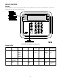
BASE FEATURES
Display
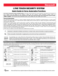
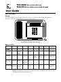
The TSSC-BASE is a wireless Control Unit that allows you to perform system arming and disarming
functions, as well as to monitor the status of your security system.
TSSC-BASE w/Protective Door Removed
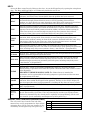
Base unit LEDs
LED
POWER
Off
Red
Amber
No AC
BATTERY
(see note 1)
Green
Flashing
Amber
Flashing
Red
Alternating
Flashing
AC
Low
Battery/
Missing
Battery
Charging
Battery Normal
STATUS
Not Ready
to Arm
Armed
System
Trouble
Ready to
Arm
NETWORK
Not
Configured
No
Ethernet
Link
Link but
Not
Connected
to Central
Station
Ethernet
Link
CELLULAR
Not
Configured
No
Connection
or Low
Signal
(see note 2)
Flashing
Green
Good
Signal
In
Programming
- Red
Device
Trouble –
Can Arm
Device
Trouble –
Cannot
Arm
Alarm/Alarm
Memory
In
Programming
- Off
In
Programming
- Green
Cell but No
Data
SIM Error
In
Programming
- Off
NOTE 1: During Sleep Mode only the BATTERY LED is active.
NOTE 2: This LED may remain in the Amber state for up to 24 Hours until a report is sent
and acknowledged by the central station.
KEYPAD FEATURES
Display
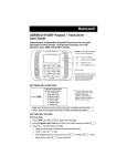
The TSSC-KP is a wireless keypad that allows you to perform your security system functions, as well as to
display the status of your security system.
TSSC-KP w/ Protective Door Removed
Keypad LEDs
LED
Off
POWER
Red
Low
Battery/
Missing
Battery
(when no
AC)
(Keypad's
battery)
TROUBLE
In
Programming,
No Trouble
STATUS
Not Ready to
Arm
Amber
Charging
Green
AC
System
Trouble
Armed
Flashing
Green
Flashing
Amber
On Battery
– Normal
(no AC)
Flashing
Red
Alternating
Flashing
Low Battery
(no AC)
(Keypad's
battery)
In
Programming
- Red
Alarm/Alarm
Memory
In
Programming
- Green
Device
Trouble
Ready to
Arm
NOTE: During Battery Mode only the POWER LED is active.
–2–
KEYS
Access the Base control keys by lifting up the door. Access the Keypad keys by opening the swing-down
door. The Base and Keypad keys are continuously backlit for ease of use.
KEY
DESCRIPTION
Disarms the burglary portion of the system, silences alarms and audible trouble
OFF
indicators, and clears visual alarm trouble after the problem has been corrected.
Completely arms both perimeter and interior burglary protection by sensing an intruder's
movements through protected interior areas as well as guarding protected doors,
AWAY
windows, etc. Late arrivals can enter through an entry delay zone (entrance door) without
causing an alarm if the system is disarmed before the entry delay time expires.
Arms the perimeter burglary protection, guarding protected doors, windows and other
perimeter protection points, and sounds an alarm if one is opened. STAY automatically
STAY
bypasses certain areas which permits movement within your house without causing an
alarm. Late arrivals can enter through an entry delay zone (entrance door) without
causing an alarm if the system is disarmed before the entry delay time expires.
Arms similar to STAY mode, but also arms additional pre-selected sensors for increased
protection while staying inside. Late arrivals can enter through an entry delay zone
NIGHT
(entrance door) without causing an alarm if the system is disarmed before the entry delay
STAY
time expires, and they do not violate any of the pre-selected sensor areas. An alarm
occurs immediately if anyone enters those areas while armed.
Arms in manner similar to AWAY mode, but eliminates the entry delay period, thus
MAX
providing maximum protection. An alarm occurs immediately upon opening any protection
point, including entry delay zones (entrance doors). (“Arm Instant,” if programmed.)
TEST
(Keypad only) - Tests the system and alarm sounder if disarmed.
(Keypad only) - Removes individual protection zones from being monitored by the system.
BYPASS
Displays previously bypassed protection zones.
Arms in manner similar to STAY mode, but eliminates the entry delay period, offering
greater security while inside and not expecting any late arrivals. An alarm will occur
INSTANT
immediately upon opening any perimeter protection point, including entry delay zones.
(“Arm Instant,” if programmed.)
(Keypad only) - Allows assigning user codes that can be given to other users of the system.
CODE
(Keypad only) - Turns on and off the CHIME mode. When on, any entry through a
protected delay or perimeter zone while the system is disarmed will cause a tone to sound
at the Keypad(s).
CHIME
IMPORTANT CHIME WARNING NOTE: The Chime feature is intended for
convenience and is not intended for life safety purposes or pool alarm and does not meet
the requirements of UL 2017.
(Keypad only) – Pressing the READY key at the Keypad prior to arming displays all open
READY
protection zones within the Keypad's home partition. This key is also used to display all
zone descriptors that have been programmed, by holding the key down at least 5 seconds.
(Keypad only) - Permits ARMING of the system without using a security code ("Quick
[#]
Arm", if programmed).
Used to enter your individual security access code(s).
Keys 0-9
Special
function
keys
Panic alarm activation (Keypad only). The panic alarms are activated by pressing a
Special Function Key (see below). Panic key functionality and the type of panic alarms
produced is determined by the control panel’s capability and programming. (Check with
your installer for the availability and assignment of these panic keys.)
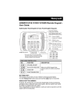
SPECIAL FUNCTION KEYS (KEYPAD ONLY)
The A, B, and C keys located to the left of the
numeric keys can be programmed as Panic Alarm
Activation keys. (Check with your installer for the
availability and assignment of these panic keys.)
–3–
Key
A
B
C
Function
GENERAL OPERATION
To make sure the latest system status is displayed, press the [*] key before and after entering each command.
HOW TO GET SYSTEM STATUS
The display continuously displays the present security system status. When there is a change in system
status (such as going from an ARMED STAY to DISARMED), it may take up to 20 seconds for the display to
automatically update the status to show the status change. However, you can press the [*] key to update the
display immediately.
ARMING THE SYSTEM
To arm the system in the AWAY, STAY, INSTANT or MAX mode, enter your user code and press the
numeric key above the selected mode.
DISARMING THE SYSTEM
To disarm the system enter your user code + OFF key [1].
BYPASSING ZONES
To bypass an individual zone, enter your user code + BYPASS key [6] + faulted zone number of the zone to
be bypassed. To bypass multiple zones, enter the command string (user code + BYPASS key [6]) then
sequentially enter the 3-digit zone numbers of the zones to be bypassed, up to five zones in each command.
Multiple Zone Bypass Example: user code + BYPASS [6] + 003 004 005 007 009.
If you want to bypass all faulted zones (Forced Bypass), enter your user code + BYPASS key [6] + [#] + [0].
The Forced Bypass feature must be enabled by your installer: [ ] yes
[ ] no
USER CODES
To Add a User
IMPORTANT: Temporary users should not be shown how to use any system function they do not need to
know (e.g. bypassing protection zones).
Enter Master code + CODE key [8] + 2-two digit user no. + 4-digit new user’s code.
User numbers 02 through 96 are available with various authority levels. User no. 01 is for the Master code.
AUTHORITY LEVEL:
Enter Master code + CODE key [8] + 2-digit user no. + [#] + [1] + single-digit authority level.
For authority levels, see definitions below.
Level
Title
Explanation
N/A
0
Master
Standard User
1
2
Arm Only
Guest
3
Duress Code
Reserved for user 01; Can perform all system functions and assign codes.
Can only perform security functions.
Cannot perform system functions reserved for the master user.
Can only arm the system. Cannot disarm or do other functions
Can arm the system and bypass zones, but cannot disarm the system unless the
system was armed with this code. This code is typically assigned to someone (e.g.,
babysitter or cleaner) who has a need to arm/disarm the system only at certain times.
Intended for use when you are forced to disarm or arm the system under threat. When
used, the system will act normally, but can silently notify the Central Monitoring Station
of your situation, if that service has been provided.
To Change a User's Code
Changing the Master code: Enter Current Master code + CODE key [8] + 01 + 4-digit new code + 4-digit new code again.
Changing a User code: Enter Master code + CODE key [8] + 2-two digit user no. + 4-digit new user’s code.
To Delete a User
Enter Master code + CODE key [8] + 2-digit user code to be deleted + # + 0. A single confirmation tone will
be heard and the code is no longer functional.
–4–
CHIME MODE
Your system can be set to alert you to the opening of a door or window while it is disarmed by using CHIME
mode. When activated, three tones sound at the Keypad whenever a protected perimeter door or window is
opened, and the “Not Ready” message is displayed. Pressing the READY [*] key displays the open protection
points.
Note that Chime mode can be activated only when the system is disarmed.
1. To turn Chime Mode on, enter the security code and press the CHIME key [9].
2. To turn Chime Mode off, enter the security code and press the CHIME key again.
KEYPAD TONES
When the Keypad is generating a periodic beep (once per minute), pressing the [*] key provides more
information.
When the system is armed and there is a trouble condition, the Keypad displays “Device Trouble”. Pressing
the [*] key provides more information.
QUICK EXIT
To start Quick Exit when enabled.
Stay Mode – Enter User code + STAY key.
Instant Mode – Enter User code + INSTANT key
Night-Stay Mode – With the system armed in Night-Stay Mode and the exit delay expired,
enter User code + STAY key + STAY key.
HOST CHECK-IN
If Host Check-In interval is set to 200 seconds, “Download Com/Upload Completed” message is displayed at
the Keypad every 200 seconds.
TEST MODE
Use Test mode to check each protection point for proper operation.
Testing should be conducted weekly to ensure proper operation.
1. Disarm the system and close all protected windows, doors, etc.
2. Enter the Master code + [5] (TEST), then press 1.
3. Listen. The external sounder should sound for about 1 second then turn off.
4. Fault all zones in turn and listen for three beeps from the keypad. ID of each faulted point should appear
on the keypad display. The display clears when the zone is closed. Note that if wireless motion detectors
are used, there is a 3-minute delay between activations. This conserves battery life.
5. Test all smoke and CO detectors following the manufacturer's instructions and check the display.
6. When all zones have been checked and are intact (closed), there should be no zone identification
numbers displayed on the keypad.
7. Exit test mode: security code + [1] (OFF).
NOTES:
• The keypad sounds a single beep about every 60 seconds as a reminder that the system is in the Test
mode.
• Alarm messages are not sent to your Central Station while Test mode is on.
• If a problem is experienced with any protection point (no confirming sounds, no display), call for service
immediately.
• If the test mode is inadvertently left active, it automatically turns off after 30 minutes. During the final
five minutes, the keypad will emit a double beep every 30 seconds.
–5–
REPLACING THE BATTERY IN A WALL MOUNTED KEYPAD
1. Remove the retaining screw at the bottom of the Keypad.
2. Press upward with your thumbs on the bottom edge of the Keypad housing and slide the Keypad up with
respect to the wall mounting plate, removing the Keypad from the wall mounting plate.
3. Remove the power harness on the old battery pack that connects to the printed circuit board.
4. Lift the old battery pack from the Keypad and replace with the new battery pack.
5. Connect the power harness to the printed circuit board.
6. Replace the Keypad onto the wall mounting plate and secure with the retaining screw.
NOTE: After replacing the battery and reattaching the Keypad to the mounting plate, enter the 4-digit
security code + OFF sequence twice to clear any trouble condition.
REPLACING THE BATTERY IN A DESK MOUNTED KEYPAD
1. Place the Keypad face down on a level surface.
2. Remove two screws and lift up Desk Stand up and away from the Keypad to expose the battery pack.
3. Remove the power harness on the old battery pack that connects to the printed circuit board.
4. Lift the old battery pack from the Keypad and replace with the new battery pack.
5. Connect the power harness to the printed circuit board.
6. Place the tabs on the Desk Stand into the appropriate slots and secure with two screws.
NOTE: After replacing the battery and reattaching the Keypad to the mounting plate, enter the 4-digit
security code + OFF sequence twice to clear any trouble condition.
–6–
THE LIMITATIONS OF THIS ALARM SYSTEM
While this system is an advanced design security system, it does not offer guaranteed protection against burglary or fire or other emergency. Any alarm system,
whether commercial or residential, is subject to compromise or failure to warn for a variety of reasons. For example:
• Intruders may gain access through unprotected openings or have the technical sophistication to bypass an alarm sensor or disconnect an alarm warning device.
• Intrusion detectors (e.g., passive infrared detectors), smoke detectors, and many other sensing devices will not work without power. Battery-operated devices
will not work without batteries, with dead batteries, or if the batteries are not put in properly. Devices powered solely by AC will not work if their AC power supply
is cut off for any reason, however briefly.
• Signals sent by wireless transmitters may be blocked or reflected by metal before they reach the alarm receiver. Even if the signal path has been recently
checked during a weekly test, blockage can occur if a metal object is moved into the path.
• A user may not be able to reach a panic or emergency button quickly enough.
• While smoke detectors have played a key role in reducing residential fire deaths in the United States, they may not activate or provide early warning for a
variety of reasons in as many as 35% of all fires, according to data published by the Federal Emergency Management Agency. Some of the reasons smoke
detectors used in conjunction with this System may not work are as follows. Smoke detectors may have been improperly installed and positioned. Smoke
detectors may not sense fires that start where smoke cannot reach the detectors, such as in chimneys, in walls, or roofs, or on the other side of closed doors.
Smoke detectors also may not sense a fire on another level of a residence or building. A second-floor detector, for example, may not sense a first-floor or
basement fire. Moreover, smoke detectors have sensing limitations. No smoke detector can sense every kind of fire every time. In general, detectors may not
always warn about fires caused by carelessness and safety hazards like smoking in bed, violent explosions, escaping gas, improper storage of flammable
materials, overloaded electrical circuits, children playing with matches, or arson. Depending upon the nature of the fire and/or the locations of the smoke
detectors, the detector, even if it operates as anticipated, may not provide sufficient warning to allow all occupants to escape in time to prevent injury or death
• Passive Infrared Motion Detectors can only detect intrusion within the designed ranges as diagrammed in their installation manual. Passive Infrared Detectors
do not provide volumetric area protection. They do create multiple beams of protection, and intrusion can only be detected in unobstructed areas covered by
those beams. They cannot detect motion or intrusion that takes place behind walls, ceilings, floors, closed doors, glass partitions, glass doors, or windows.
Mechanical tampering, masking, painting or spraying of any material on the mirrors, windows or any part of the optical system can reduce their detection ability.
Passive Infrared Detectors sense changes in temperature; however, as the ambient temperature of protected area approaches the temperature range of 90° to
105°F, the detection performance can decrease.
• Alarm warning devices such as sirens, bells, or horns may not alert people or wake up sleepers if they are located on the other side of closed or partly open
doors. If warning devices sound on a different level of the residence from the bedrooms, then they are less likely to waken or alert people inside the bedrooms.
Even persons who are awake may not hear the warning if the alarm is muffled from a stereo, radio, air conditioner or other appliance, or by passing traffic.
Finally, alarm warning devices, however loud, may not warn hearing-impaired people or waken deep sleepers.
• Telephone lines needed to transmit alarm signals from a premises to a central monitoring station may be out of service or temporarily out of service. Telephone
lines are also subject to compromise by sophisticated intruders.
• Even if the system responds to the emergency as intended, however, occupants may have insufficient time to protect themselves from the emergency situation.
In the case of a monitored alarm system, authorities may not respond appropriately.
• This equipment, like other electrical devices, is subject to component failure. Even though this equipment is designed to last as long as 10 years, the electronic
components could fail at any time.
The most common cause of an alarm system not functioning when an intrusion or fire occurs is inadequate maintenance. This alarm system should be tested
weekly to make sure all sensors and transmitters are working properly.
Installing an alarm system may make one eligible for lower insurance rates, but an alarm system is not a substitute for insurance. Homeowners, property owners,
and renters should continue to act prudently in protecting themselves and continue to insure their lives and property.
We continue to develop new and improved protection devices. Users of alarm systems owe it to themselves and their loved ones to learn about these
developments.
FEDERAL COMMUNICATIONS COMMISSION & INDUSTRY CANADA STATEMENTS FOR TSSC_BASE
FCC ID: CFS8DLTSSCBASE, IC: 573F-TSSCBASE, IC MODEL: TSSCBASE
The user shall not make any changes or modifications to the equipment unless authorized by the Installation Instructions or User's Manual. Unauthorized changes
or modifications could void the user's authority to operate the equipment.
CLASS B DIGITAL DEVICE STATEMENT
This equipment has been tested to FCC requirements and has been found acceptable for use. The FCC requires the following statement for your information:
This equipment generates and uses radio frequency energy and if not installed and used properly, that is, in strict accordance with the manufacturer's instructions,
may cause interference to radio and television reception. It has been type tested and found to comply with the limits for a Class B computing device in accordance
with the specifications in Part 15 of FCC Rules, which are designed to provide reasonable protection against such interference in a residential installation.
However, there is no guarantee that interference will not occur in a particular installation. If this equipment does cause interference to radio or television reception,
which can be determined by turning the equipment off and on, the user is encouraged to try to correct the interference by one or more of the following measures:
• If using an indoor antenna, have a quality outdoor antenna installed.
• Reorient the receiving antenna until interference is reduced or eliminated.
• Move the radio or television receiver away from the receiver/control.
• Move the antenna leads away from any wire runs to the receiver/control.
• Plug the receiver/control into a different outlet so that it and the radio or television receiver are on different branch circuits.
• Consult the dealer or an experienced radio/TV technician for help.
INDUSTRY CANADA CLASS B STATEMENT
This Class B digital apparatus complies with Canadian ICES-003.
Cet appareil numérique de la classe B est conforme à la norme NMB-003 du Canada.
FCC / IC STATEMENT
This device complies with Part 15 of the FCC Rules, and RSS210 of Industry Canada. Operation is subject to the following two conditions: (1) This device may not
cause harmful interference, and (2) This device must accept any interference received, including interference that may cause undesired operation.
Cet appareil est conforme à la partie 15 des règles de la FCC & de RSS 210 des Industries Canada. Son fonctionnement est soumis aux conditions suivantes: (1)
Cet appareil ne doit pas causer d’interférences nuisibles. (2) Cet appareil doit accepter toute interférence reçue y compris les interférences causant une réception
indésirable.
RF Exposure
Warning – The antenna(s) used for this device must be installed to provide a separation distance of at least 7.8 inches (20 cm) from all persons and must not
be co-located or operating in conjunction with any other antenna or transmitter except in accordance with FCC multi-transmitter product procedures.
Mise en Garde
Exposition aux Frequences Radio: L'antenne (s) utilisée pour cet émetteur doit être installée à une distance de séparation d'au moins 7,8 pouces (20
cm) de toutes les personnes.
–7–
LIMITED WARRANTY
Terms and Conditions Applying to Sale of Equipment
1. Limited Warranty.
Any part of the system, including the wiring, installed under this Agreement which proves to be defective in material or workmanship within 90
days of the date of completion of installation will be repaired or replaced at ADT's option with a new functionally operative part. Labor and
material required to repair or replace such defective components or to make mechanical adjustments to the system will be free of charge for a
period of 90 days following the completion of the original installation.
This warranty is extended only to the original consumer purchaser of the system and may be enforced only by such person.
To obtain service under this warranty, call or write our local ADT Service Department at the telephone number or address found in your local
yellow pages.
Service pursuant to the warranty will be furnished only during ADT's normal working hours 8:00A.M. to 4:30P.M., Monday through Friday,
except holidays. Services rendered outside the normal working hours of ADT are not within the scope of this warranty and any services
requested to be performed at such times shall be charged for at ADT's then applicable rates for labor and material.
This warranty does not apply to the conditions listed below, and in the event customer calls ADT for service under the warranty and upon
inspection it is found that one of these conditions has led to the inoperability or apparent inoperability of the system, a charge will be made for
the service call of the ADT representative, whether or not he actually works on the system. Should it actually be necessary to make repairs to
the system due to one of the "conditions Not Covered By Warranty", a charge will be made for such work at ADT's then applicable rates for
labor and material.
Conditions Not Covered By Warranty.
Damage from accidents, acts of God, alterations, misuse, tampering or abuse. B. Failure of the customer to properly close or secure a door,
window, or other point protected by a burglar alarm device. C. Failure of customer to properly follow operating instructions provided by ADT at
time of installation or at a later date. D. Trouble in leased telephone. E. Trouble due to interruption of commercial power. F. Battery
replacements.
This warranty is in lieu of all other express warranties. Any implied warranties of merchantability and fitness for a particular purpose are limited
in duration to a period of 90 days from the date of completion of installation. The exclusive remedy of the customer hereunder shall be repair
or replacement as stated above. Under no circumstances shall ADT be liable to the customer or any other person for incidental or
consequential damages of any nature, including without limitation, damages for personal injury or damages to property, and, however
occasioned, whether alleged as resulting from breach of warranty by ADT, the negligence of ADT, or otherwise, ADT's liability will in no event
exceed the purchase price of the system. Some states may not allow limitations on how long an implied warranty lasts, or the exclusion or
limitations of incidental or consequential damages, so the above limitations and exclusions may not apply to you, unless a longer period is
required by applicable law. Any action against ADT in connection with a system must be commenced within one year after the cause of action
has occurred.
No agent, employee or representative of ADT or any other person is authorized to modify this warranty in any respect.
This warranty gives you specific legal rights and you may also have other rights which vary from state to state.
2. Installation.
ADT agrees to install the equipment in a workmanlike manner in accordance with the following conditions:
Customer will make premises available without interruption during ADT normal working hours 8:00A.M. to 4:30P.M., Monday through Friday,
except Holidays. B. Customer understands that the installation will necessitate drilling into various parts of the premises: ADT intends,
generally, to conceal wiring in the finished areas of the premises; however, there may be areas which, due to construction, decoration, or
furnishing of the premises, ADT determines, in its sole discretion, that it would be impractical to conceal wiring and, in such cases, wiring will
be exposed. C. Customer agrees to provide 110 VAC electrical outlets at designated locations for equipment requiring AC power. D.
Customer to provide for lifting and replacing carpeting, if required, for installation of floor mats or wiring.
ALL RIGHTS RESERVED
No part of this publication may be reproduced, stored in a retrieval system, or transmitted in any form, or by any means – electronic,
mechanical, photocopying, recording, or otherwise without the written permission of ADT Security Services. The material in this publication is
for information purposes and subject to change without notice. ADT Security Services assumes no responsibility for any errors which may
appear in this publication.
ADT Security Services
1501 Yamato Rd
Boca Raton, FL 33431
Copyright © 2013
Ê800-13959ÈŠ
800-13959 11/13 Rev. D