1
SV200 AC Servo
User Manual
920-0096B
9/1/2015
920-0096B
9/1/2015
SV200 Hardware Manual
Table of Contents
1 Introduction.................................................................................7
1.1 About This Manual ............................................................................. 7
1.2 Documentation Set for SV200 series AC servo ................................. 7
1.3 Safety................................................................................................. 7
1.4 Safety Symbols.................................................................................. 7
1.5 Safety Instructions...................................................................8
Installation................................................................................................ 8
Wiring....................................................................................................... 8
1.6 Standards Compliance................................................................... 8
2. Product Description...................................................................9
2.1 Unpacking Check............................................................................... 9
2.2 Servo Drive Model Introduction.......................................................... 9
2.2.1 Drive Name Plate Description.............................................................9
2.2.2 Drive Model Description......................................................................10
2.2.3 Drive specification...............................................................................11
2.2.4 Drive Dimensions (Unit: mm)..............................................................12
2.3 Servo Motor Model Introduction...............................................13
2.3.1 Motor Name Plate Description........................................................ 13
2.3.2 Motor Model Description................................................................. 13
2.3.3 Motor Specification And Dimension................................................. 14
□ 40mm Series......................................................................................... 14
40mm Dimensions......................................................................................15
□ 40mm Torque curve..................................................................................16
2.3.3.2 □60mm Specification and Dimension...............................................17
60mm Dimensions.......................................................................................18
□ 60mm Torque curves .......................................................................... 19
2.3.3.3 □80mm Specification and Dimension........................................... 20
□ 80mm Torque Curve.............................................................................. 23
2.5 System Configuration..............................................................25
3.Installation...................................................................................26
3.1 Storage Conditions............................................................................. 26
3.2 Installation Conditions........................................................................ 26
3.4 Installation Space.............................................................................. 27
3.5 Motor Installation.....................................................................28
4. Connections and Wiring.............................................................29
4.1 Connecting to Peripheral Devices...................................................... 29
4.1.1 System Configuration..........................................................................29
4.1.2 Servo Drive Connectors and Terminals........................................... 30
4.1.3 Connections and Wiring Notes........................................................ 30
4.1.4 Wiring Methods For Power supply P1............................................. 31
4.1.4.1 Single-Phase Power Supply Connection (AC220V).........................31
4.1.4.2 Three-Phase Power Supply Connection (AC220V).........................32
4.2 Wiring to the Connector P2......................................................33
4.2.1 Motor Power Cable Configuration .................................................. 33
4.2.2 Motor Power Cable Connector Specifications................................. 33
4.2.3 Wiring Diagram Of Motor Extension Cable..................................... 34
2
SV200 Hardware Manual
4.3 Encoder Connector CN3..........................................................34
4.3.1 Motor Encoder Feedback Cable Configuration............................... 34
4.3.2 The Layout of CN3 Connector......................................................... 35
4.3.3 Connect to Motor Encoder.............................................................. 36
4.3.4 Specifications of Encoder Connector.............................................. 36
15PIN AMP Connector............................................................................. 36
4.3.5 Wiring Diagram of Motor Encoder Extend Cable............................ 37
4.4 Electromagnetic Brake.............................................................38
4.4.1 Wiring Diagram................................................................................ 38
4.4.2 Brake Motor..................................................................................... 38
4.4.3 Timing Charts Of The Electromagnetic Brake................................. 39
4.5 Regenerative Resistor.............................................................40
4.7 Connect to Host Computer,CN1..............................................40
4.8 Input and Output Signal Interface Connector,CN2..................41
4.8.1 Input and Output Interface Specifications and Diagram.................. 41
4.8.2 Signals Description of Connector CN2............................................ 43
4.8.2.1 The Layout of CN2 Connector..........................................................43
4.8.2.2 Input Signals.....................................................................................43
4.8.2.3 Inputs Function List..........................................................................45
4.8.2.4 Output Signals..................................................................................45
4.8.2.5 Outputs Function List.......................................................................46
4.8.3 Input Signal Interface Connector CN2............................................. 46
4.8.3.1 Position pulse signal input................................................................46
4.8.4 CN2 Output Signal Specification..................................................... 55
4.8.4.1 CN2 Output Signal Diagram.............................................................55
4.8.4.2 Y1, Y2, Y5, Y6 Output Connection Diagram....................................55
4.8.4.3 Y3, Y4 Connection Examples...........................................................56
4.8.5 Encoder Feedback Output.............................................................. 56
4.8.5.1 A/B/Z Connection Diagram...............................................................56
4.8.5.2 Z Phase Open Collector Output.......................................................56
5.Display and Operation................................................................57
5.1 Description of Control Panel............................................................... 57
5.2 Mode Switch Control.......................................................................... 57
5.3 LED display description...........................................................59
5.3.1 Decimal Point And Negative Sign Description................................. 59
5.3.2 Parameter View Setting................................................................... 59
5.3.3 Parameter Save Setting.................................................................. 59
5.3.4 Point To Point Motion Mode ........................................................... 59
5.3.5 Jog Mode......................................................................................... 60
5.3.6 Control Panel Lock.......................................................................... 60
5.4 Status Monitoring Selection Mode...........................................60
5.5 Function Mode Control............................................................62
5.5.1 Function Mode Description.............................................................. 62
5.6 Parameter Setting Mode..........................................................64
5.6.1 Parameter Setting Description........................................................ 64
5.6.2 Parameter Editing Examples........................................................... 65
5.7 Control Panel Lock..................................................................66
3
920-0096B
9/1/2015
920-0096B
9/1/2015
SV200 Hardware Manual
5.8 Warning And Fault Display......................................................66
6. Preoperational mode.................................................................68
6.1 Inspection Before Trial Run................................................................ 68
6.2 Trial Run Procedure........................................................................... 68
6.3 Manual Motor Configuration............................................................... 69
6.3.1 Use Drive Control Panel To Setup.......................................................69
6.3.2 Using Software To Configure Motor....................................................70
6.4 Using JOG Mode.....................................................................71
6.5 Configuration by Personal Computer.......................................72
7. Operation Mode Selection.........................................................73
7.1 General Function Setting.................................................................... 73
7.1.1 Drive Servo on settings.......................................................................73
7.1.2 Alarm Reset..................................................................................... 74
7.1.3 CW/CCW limit................................................................................. 75
7.1.4 Global Gain Switch Function........................................................... 76
7.1.5 Control Mode Switch....................................................................... 77
7.1.6 Drive On Fault Output..................................................................... 78
7.1.7 Motor Brake Control ....................................................................... 79
7.1.8 Servo Ready Output ....................................................................... 80
7.2 Position Mode .........................................................................80
7.2.1 Digital Pulse Position Mode Connection Diagram........................... 81
7.2.2 Input Pulse Type And Input Noise Filter ......................................... 82
7.2.2.1 Input Pulse Type Setting..................................................................82
7.2.2.2 Input Noise Filter Setting..................................................................82
7.2.2.3 Parameter P-43 (SZ) Setting............................................................83
7.2.3 Control Pulse Dividing Switch Function........................................... 84
7.2.4 Pulse Inhibit Function ..................................................................... 85
7.2.5 Electronic Gearing Ratio................................................................. 85
7.2.6 Jerk Smoothing Filter...................................................................... 86
7.2.7 In-Position Error Output................................................................... 87
7.2.8 Gain Parameters For Position Control Mode.................................. 87
7.2.9 Software Configuration For Position Mode...................................... 88
7.3 Velocity Mode .................................................................................... 89
7.3.1 Velocity Mode Connection Diagram................................................ 90
7.3.2 Parameter Settings For Analog Velocity Control Mode................... 91
7.3.3 Basic Settings For Analog Velocity Control Mode........................... 91
7.3.3.1 Command Signal For Analog Velocity Mode....................................91
7.3.3.2 Analog Velocity Gain........................................................................92
7.3.3.3 Analog Input Voltage Offset..............................................................93
7.3.3.4 Analog Input Deadband....................................................................94
7.3.3.5 Run/Stop And Direction Signal ........................................................95
7.3.3.6 Torque Limit .....................................................................................96
7.3.3.7 Target Velocity Reached...................................................................97
7.3.4 Analog Input Filter........................................................................... 98
7.3.5 Software Configuration For Analog Velocity Mode.......................... 99
7.4 Torque Mode............................................................................100
7.4.1 Analog Torque Mode Connection Diagram...................................... 101
7.4.2 Parameters For Analog Torque Mode............................................. 102
4
SV200 Hardware Manual
920-0096B
9/1/2015
7.4.3 Basic Settings For Analog Torque Mode......................................... 102
7.4.3.1 Command Signal For Analog Torque Mode ....................................102
7.4.3.2 Analog Torque Gain..........................................................................103
7.4.3.3 Analog Input Offset...........................................................................104
7.4.3.4 Analog Deadband.............................................................................104
7.4.3.5 Run/Stop and Direction signal .........................................................105
7.4.3.6 Velocity Limit ...................................................................................105
7.4.3.7 Torque Reached ..............................................................................106
7.4.4 Software Configuration For Analog Torque Mode........................... 107
8. Parameters and Functions ........................................................108
8.1 Parameter Category........................................................................... 108
8.2 Parameter List.................................................................................... 109
8.3 Parameter Description.............................................................113
9. Communication .........................................................................136
9.1 RS-232 communication...................................................................... 136
9.1.1 What is SCL.................................................................................... 136
9.1.2 RS-232 Connections....................................................................... 136
9.2 RS-485 Communication...........................................................137
9.2.1 RS-485 PIN definition ..................................................................... 137
9.2.2 RS-485 Connection Method ........................................................... 138
9.3 ModBUS/RTU Communication................................................139
9.3.1 Data Encoding................................................................................. 139
9.3.2 Communication Address................................................................. 140
9.3.3 Communication Baud Rate And Framing........................................ 140
9.3.4 Power Up Mode .............................................................................. 140
9.3.5 Modbus/RTU Data Framing............................................................ 140
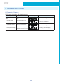
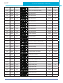
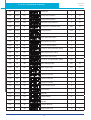
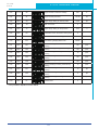
9.3.6 SV200 Series AC Servo Drive Register Address And Function List:
9.3.7 Command Opcode description........................................................ 143
9.3.8 Function Code................................................................................. 144
9.3.8.1 Function Code 0X03, Reading Multiple Holding Registers..............144
9.3.8.2 Function Code 0x06, Writing Single Register...................................145
9.3.8.3 Function Code 0X10, Writing Multiple Registers .............................146
9.3.9 Modbus/RTU Applications .............................................................. 147
9.3.9.1 Position Control ...............................................................................147
9.3.9.2 JOG mode........................................................................................150
9.4 CANopen Communication.......................................................153
9.4.1 RJ45 (8p8c) Pin Definitions............................................................. 153
9.4.2 CANopen NODE-ID......................................................................... 153
9.4.3 CANopen Communication Baud Rate ............................................ 153
9.4.4 Setting IP Address via the Front Control Panel ........................... 154
9.4.5 Setting IP address with SVX ServoSUITE.............................................155
9.4.6 How to edit the IP address table in SVX ServoSUITE................. 155
9.4.7 Read IP address from drive, Save IP address to the disk:....................156
10.Trouble Shooting......................................................................157
10.1 Drive Alarm List................................................................................ 157
10.2 Drive alarm troubleshooting ..................................................158
5
141
920-0096B
9/1/2015
SV200 Hardware Manual
Revision History
Document History
Date
Revision A
2015.8.5
Remarks
Disclaimer
The information in this manual was accurate and reliable at the time of its release. AMP reserves the right
to change the specifications of the product described in this manual without notice at any time.
Trademarks
All marks in this manual are the property of their respective owners
Customer Service
AMP is committed to delivering quality customer service and support for all our products. Our goal is to
provide our customers with the information and resources so that they are available, without delay, if and
when they are needed.
In order to serve in the most effective way, we recommend that you contact your local sales representative
for order status and delivery information, product information and literature, and application and field
technical assistance. If you are unable to contact your local sales representative for any reason, please
use the most relevant of the contact details below:
For technical support, contact: http://www.applied-motion.com/support
6
920-0096B
9/1/2015
SV200 Hardware Manual
1 Introduction
1.1 About This Manual
This manual describes the SV200 Servo Drive.
It provides the information required for installation, configuration and basic operation of the SV200 series
AC servo drive.
This document is intended for persons who are qualified to transport, assemble, commission, and
maintain the equipment described herein.
1.2 Documentation Set for SV200 series AC servo
This manual is part of a documentation set. The entire set consists of the following:
• SV200 User Manual. Hardware installation, configuration and operation.
• SVX ServoSUITE® User Manual. How to use the SVX ServoSUITE®.
1.3 Safety
Only qualified persons may perform the installation procedures. The following explanations are for things
that must be observed in order to prevent harm to people and damage to property.
The SV200 utilizes hazardous voltages. Be sure the drive is properly grounded.
Before you install the SV200, review the safety instructions in this manual.
Failure to follow the safety instructions may result in personal injury or equipment damage.
1.4 Safety Symbols
Safety symbols indicate a potential for personal injury or equipment damage if the recommended
precautions and safe operating practices are not followed.
The following safety-alert symbols are used on the drive and in the documentation:
Caution
Warning. Dangerous voltage.
7
Protective earth
Caution, Hot surface
920-0096B
9/1/2015
SV200 Hardware Manual
1.5 Safety Instructions
Installation
DO NOT subject the product to water, corrosive or flammable gases, and combustibles.
DO NOT use the motor in a place subject to excessive vibration or shock.
Never connect the motor directly to the AC power supply.
DO NOT use cables soaked in water or oil.
DO NOT extrude or pull-off the cable, nor damage the cables as electrical shocks, as damage may result
DO NOT block the heat-dissipating holes. Please prevent any metal filings from dropping into into the drive
when mounting.
DO NOT switch the power supply repeatedly.
DO NOT touch the rotating shaft when the motor is running.
DO NOT strike the motor when mounting as the motor shaft or encoder may be damaged.
In order to prevent accidents, the initial trial run for servo motor should be conducted
under no-load conditions (separate the motor from its couplings and belts).
Starting the operation without matching the correct parameters may result in servo drive or motor damage,
or damage to the mechanical system.
DO NOT touch either the drive heat sink or the motor and regenerative resistor during operation as they
may become hot.
DO NOT carry the motor by its cables.
Wiring
DO NOT connect any power supplies to the U,V,W terminals.
Install the encoder cable in a separate conduit from the motor power cable to avoid signal noise.
Use multi-stranded twisted-pair wires or multi-core shielded-pair wires for signal, encoder cables.
As a charge may still remain in the drive with hazardous voltage even after power has been removed, Do
not touch the terminals when the charge LED is still lit.
Please observe the specified voltage ratings.
Make sure both the drive and the motor connect to a class 3 ground.
Please ensure grounding wires are securely connected when power up.
1.6 Standards Compliance
The SV200 Series AC servo drive has been designed according to standards:
* Electromagnetic compatibility
Standard EN 61800-3 (2004)
* Electrical Safety: Low voltage directive
Standard IEC 61800-5-1 (2007)
8
920-0096B
9/1/2015
SV200 Hardware Manual
2. Product Description
2.1 Unpacking Check
Please refer to this section to confirm the model of servo drive and servo motor .
A complete and workable AC servo system should include the following parts:
*
*
*
*
*
*
*
*
*
*
Matched Servo drive and Servo motor
A power cable connect the drive to the servo motor
A feedback encoder cable connecting the drive to the motor
A mini (Type B) USB cable connect the port CN1 to PC for communication. (Not
needed for Ethernet drives)
50-PIN connector (For I/O connections, Port CN2)
26-PIN connector(For encoder feedback, Port CN3 )
10-PIN connector (For STO, Port CN5) (Required)
RJ-45 CAT5 patch cables (For RS-485, Ethernet or CANopen communication, Port
CN6 and CN7)(user supplied)
5-PIN connector (For L1,L2,L3,L1C,L2C)
6-PIN connector(For U,V,W,B1+,B2,B3)
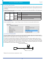
2.2 Servo Drive Model Introduction
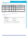
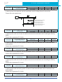
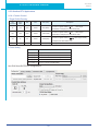
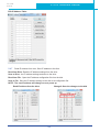
2.2.1 Drive Name Plate Description
RoHS
Assembled in China
SV200
Model No.
Input/Output Voltage
Phase
Rated Current
Frequency
Rated Power
AC SERVO
DRIVE
Serial No.
09450001
Model No. XXXX-XXXXX
VOLT.
PHASE
F.L.C
FREQ.
POWER
9
INPUT
OUTPUT
200-240VAC
1φ/3φ
2.6 A/1.5A
50/60Hz
0-240VAC
3φ
1.8 A
0-400Hz
200W
920-0096B
9/1/2015
SV200 Hardware Manual
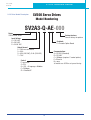
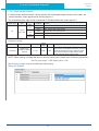
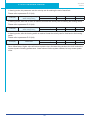
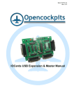
2.2.2 Drive Model Description
SV200 Servo Drives
Model Numbering
SV2A3-Q-AE-000
Series
SV200 Servo Series
Custom features
Consult factory for options
Input Voltage
A = 120 VAC
B = 220 VAC
D = 24-80 VDC
Feedback
E = Encoder Option Board
Output Current
2 = 1.8A rms continuous
3 = 3.0A
5 = 4.5A (220 VAC), 5.4A (120 VAC)
7 = 7.0A
Communications
A = RS-232 (Standard)
R = RS-485
C = CANopen (requires C control option)
E = Ethernet
N = none
all models use USB for set up and tuning
Control
P = pulse/dir
S = SCL
Q = SCL + Q language + Modbus
C = CANopen
IP = EtherNet/IP
Planned 120V Models
100/200W
200/400W
SV2A2-P-NE
SV2A3-P-NE
400/750W
SV2A5-P-NE
Planned 220V Models
100/200W
200/400W
SV2B2-P-NE
SV2B3-P-NE
400/750W
SV2B5-P-NE
SV2A2-Q-AE
SV2A2-Q-RE
SV2A2-Q-EE
SV2A3-Q-AE
SV2A3-Q-RE
SV2A3-Q-EE
SV2A5-Q-AE
SV2A5-Q-RE
SV2A5-Q-EE
SV2B2-Q-AE
SV2B2-Q-RE
SV2B2-Q-EE
SV2B3-Q-AE
SV2B3-Q-RE
SV2B3-Q-EE
SV2B5-Q-AE
SV2B5-Q-RE
SV2B5-Q-EE
SV2A2-C-CE
SV2A3-C-CE
SV2A5-C-CE
SV2B2-C-CE
SV2B3-C-CE
SV2B5-C-CE
SV2A2-IP-EE
SV2A3-IP-EE
SV2A5-IP-EE
SV2B2-IP-EE
SV2B3-IP-EE
SV2B5-IP-EE
10
935-0016B - SV200 Part Numbering System
SV200 Hardware Manual
920-0096B
9/1/2015
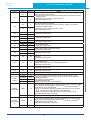
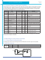
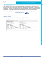
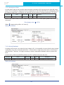
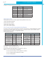
2.2.3 Drive specification
200W
Input
Power
400W
750W
Main Circuit
Single/3-phase, 220VAC, ±10% 50/60Hz
Control Circuit
Single phase, 220VAC, ±10% 50/60Hz
Main Circuit
Single/3-phase, 220VAC, ±10% 50/60Hz
Control Circuit
Single phase, 220VAC, ±10% 50/60Hz
Main Circuit
Single/3-phase, 220VAC, ±10% 50/60Hz
Control Circuit
Single phase, 220VAC, ±10% 50/60Hz
Withstand voltage
Environment
Primary to earth: withstand 1500 VAC, 1 min, (sensed current: 20 mA) [220V Input]
Temperature
Ambient temperature:0°C to 40°C (If the ambient temperature of servo drive is
greater than 45°C, please install the drive in a well-ventilated location) Storage
temperature: -20°C to 65C. Operating temperature: 0°C to 85°C.
Humidity
Both operating and storage : 10 to 85%RH or less
Vibration
5.88m/s2 or less, 10 to 60Hz (No continuous use at resonance frequency)
Weight
SV2B2: 1.86 lbs; SV2B3: 2.65 lbs; SV2B5: 3.60 lbs
Control method
IGBT PWM Sinusoidal wave drive
Encoder feedback
2500 line incremental encoder 15-wire
Basic Specification
Control
Signal
Input
Output
I/O
Analog
signal
Input
8 Configurable Optically isolated digital general inputs, 5-24VDC, max input current
20mA
4 Configurable Optically isolated digital high speed inputs, 5-24VDC, max input
current 20mA
5 Configurable optically isolated digital outputs, 30VDC, max output current 30mA
One motor brake control output, 30VDC 100mA max
2 inputs (12Bit A/D : range: + /- 10VDC)
2 inputs (Photo-coupler input, Line receiver input)
Pulse signal
Input
Line receiver input is compatible with line driver I/F.
Output
Communication
Photocoupler input is compatible with both line driver I/F and open collector I/F.
4 outputs ( Line driver: 3 outputs, open collector: 1 output)
USB Mini type B
Connection with PC or 1 : 1 communication to a host.
RS232
RS-232 Communication
RS485
RS-485 Communication
CAN bus
CANopen Communication
Ethernet
EtherNET/IP,eSCL
Front panel
1. 4 keys (MODE, UP, DOWN, SET) 2. LED (5-digit)
Regeneration Resistor
Built-in regenerative resistor (external resistor is also enabled.)
Control mode
(1) Position mode
(2) Analog Velocity mode
(3) Analog Position mode
(4) Position mode
(5) Velocity Change mode
(6) Command Torque mode
(7) Command Velocity mode
Control input
(1) Servo-ON input
(2) Alarm clear input
(3) CW/CCW Limit
(4) Pulse& Direction or CW/CCW input
(5) Gain Switch
(6) Control mode Switch
(7) Pulse Inhibit
(8) General Input
Control output
(1) Alarm output
(2) Servo-Ready output
(3) External brake release
(4) Speed Reached output
(5) Torque Reached output
(6) TachOut
(7) General Output
(8)Position Reached output
11
920-0096B
9/1/2015
SV200 Hardware Manual
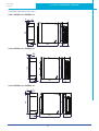
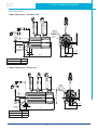
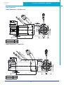
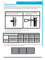
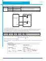
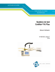
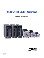
2.2.4 Drive Dimensions (Unit: mm)
2.2.4.1 SV2A2-x-xx, SV2B2-x-xx
6
140
150
5
Ø5
5
41
145
35.5
2.2.4.2 SV2A3-x-xx, SV2B3-x-xx
Ø5
150
140
5
6
49.5
5
145
55
2.2.4.3 SV2A5-x-xx, SV2B5-x-xx
7.5
2
5.
150
140
5
Ø
5.2
57.5
176
12
65
920-0096B
9/1/2015
SV200 Hardware Manual
2.3 Servo Motor Model Introduction
2.3.1 Motor Name Plate Description
Model NO.
Series NO.
Rated Torque
Input Current
Output Power
Rated Speed
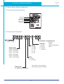
2.3.2 Motor Model Description
J = Metric Flange
Wattage Rating
0050 = 50 watts
0100 = 100 watts
0200 = 200 watts
0400 = 400 watts
0750 = 750 watts
1000 = 1000 watts
Voltage
1 = 100
2 = 200
3 = 24
4 = 48
5 = 60
Custom Features - Consult factory for
Keyway
Flat(s)
Frame Size
Optional Gearhead
3 = 40mm
Other
4 = 60mm
5 = 80mm
7 = 100mm
Brake
0 = None
5 = Included
Consult Price List or Catalog
for standard product offering
Feedback Type
3 = 2500 line inc. encoder
13
920-0096B
9/1/2015
SV200 Hardware Manual
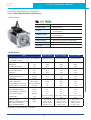
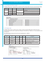
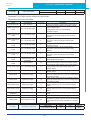
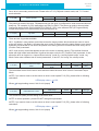
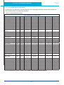
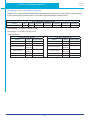
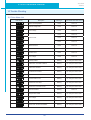
2.3.3 Motor Specification And Dimension
2.3.3.1 □40mm Specification and Dimension
□ 40mm Series
UL File
E465363
Insulation Class
Class B(130°C)
IP rating
IP65 (except shaft through hole and cable
end connector)
Installation location
Indoors, free from direct sunlight, corrosive gas,
inflammable gas
Ambient temperature
Operating 0 to 40°C, Storage -20 to 80 C
Ambient humidity
85%RH or lower (free from condensing)
Vibration Resistance
49 m/s2
Rotor Poles
8
□ 40mm Series
Series
Base Model Number
(with 2500 PPR incremental encoder non-sealed plastic connectors, no brake)
Rated Output Power
watts
Rated Speed
rpm
Max. Mechanical Speed
rpm
Rated Torque
Nm
Continuous Stall Torque
Nm
Peak Torque
Nm
Rated Current
A (rms)
Continuous Stall Current
A (rms)
Peak Current
A (rms)
Voltage Constant ±5%
V (rms) / K rpm
Torque Constant ±5%
Nm / A (rms)
Winding Resistance (Line-Line)
Ohm ±10% @25°C
Winding Inductance (Line-Line)
mH (typ.)
Inertia (with encoder)
g-cm2
Inertia - With Brake Option
g-cm2
Thermal Resistance (mounted)
°C / W
Thermal Time Constant
Minutes
Heat Sink Size
Shaft Load - Axial
Shaft Load - Radial (End of Shaft)
Weight (with std. encoder)
Weight - With Brake Option
mm
(max.)
(max.)
J0050 - 50 Watt
J0100 - 100 Watt
J0100 - 100 Watt
J0050-302-3-000
J0100-301-3-000
J0100-302-3-000
50
3000
6000
0.19
0.2
0.48
0.7
1.75
1.7
17
0.283
27
26
23.2
28
2.9
12
120 x 120 x 5 Aluminum
50 N / 11 Lb
50 N / 11 Lb
0.4 kg / 0.9 Lb
0.65 kg / 1.4 lb
100
3000
6000
0.32
0.34
0.93
1.65
1.27
4.95
20.4
0.195
4.9
5.9
42.2
52.2
2.4
14.5
120 x 120 x 5 Aluminum
50 N / 11 Lb
60 N / 13.5 Lb
0.55 kg / 1.2 Lb
0.8 kg / 1.8 lb
100
3000
6000
0.32
0.34
0.93
1.2
1.27
3.6
16.6
0.271
9.7
11.5
42.2
52.2
2.4
14.5
120 x 120 x 5 Aluminum
50 N / 11 Lb
60 N / 13.5 Lb
0.55 kg / 1.2 Lb
0.8 kg / 1.8 lb
Shaft Load: (L10 life, 20,000 hours, 2,000 RPM)
14
920-0096B
9/1/2015
SV200 Hardware Manual
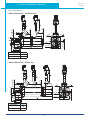
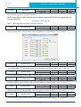
40mm Dimensions
58
53
0
- 0.009
300 50
300 50
1 Motor Dimensions – No Brake: mm
8 h6
0.04 A
0
- 0.021
5
46
M3
8
A
2.5 0.2
9.2
25 1
-KEY
4.2
0
- 0.025
4-
Oil seal
+0.20
- 0.13
40
L1 1
3 h9
30 h7
0.5
0.04 A
Without Brake
J0050-30x-3
J0100-30x-3
L1
92
109
53.4
5
46
25 1
9.2
+0.20
- 0.13
40
L1 1
0.04 A
With Brake
J0050-35x-3
J0100-35x-3
4.2
0
- 0.025
2.5 0.2
4-
-KEY
58
Oil seal
A
3
L1
129
147
15
3 h9
0
- 0.021
8 h6
0.04 A
0.5
30 h7
300 50
300 50
0
- 0.009
300 50
2 Motor Dimensions – Brake: mm
920-0096B
9/1/2015
SV200 Hardware Manual
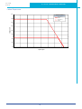
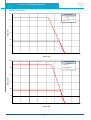
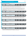
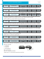
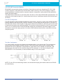
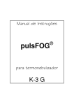
□ 40mm Torque curve
160
SV2A2 and SV2A3
J0100-301-3
1.65A
140
J0100-301-3
4.95A
120
torque, oz-in
100
80
60
40
20
0
0
1000
2000
3000
4000
speed, rpm
16
5000
6000
7000
8000
920-0096B
9/1/2015
SV200 Hardware Manual
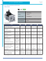
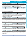
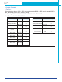
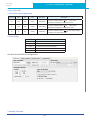
2.3.3.2 □60mm Specification and Dimension
□ 60mm Series
UL File
E465363
Insulation Class
Class B(130°C)
IP rating
IP65(except shaft through hole and cable end
connetor)
Installation location
Indoors, free from direct sunlight, corrosive gas,
inflammable gas
Ambient temperature
Operating 0 to 40°C, Storage -20 to 80°C
Ambient humidity
85%RH or lower (free from condensing)
Vibration Resistance
49 m/s2
Rotor Poles
8
□ 60mm Series
Series
J0200 - 200 Watt J0200 - 200 Watt J0400 - 400 Watt J0400 - 400 Watt
Base Model Number
(with 2500 PPR incremental
encoder non-sealed plastic connectors, no brake)
Rated Output Power
watts
J0200-301-4-000 J0200-302-4-000 J0400-301-4-000 J0400-302-4-000
200
200
400
400
Rated Speed
rpm
3000
3000
3000
3000
Max. Mechanical Speed
rpm
6000
6000
6000
6000
Rated Torque
Nm
0.64
0.64
1.27
1.27
Continuous Stall Torque
Nm
0.68
0.68
1.27
1.27
Peak Torque
Nm
1.9
1.9
3.8
3.8
Rated Current
A (rms)
1.5
1.5
2.7
2.7
Continuous Stall Current
A (rms)
1.5
1.5
2.7
2.7
Peak Current
A (rms)
4.5
4.5
8.1
8.1
Voltage Constant ±5%
V (rms) / K
rpm
27.2
27.2
29
29
Torque Constant ±5%
Nm / A (rms)
0.432
0.432
0.484
0.484
Winding Resistance (Line-Line)
Ohm ±10%
@25°C
8.6
8.6
3.7
3.7
mH
25
25
12.9
12.9
g-cm2
94
94
190
190
g-cm
140
140
240
240
Winding Inductance (Line-Line)
Inertia (with encoder)
Inertia - With Brake Option
Thermal Resistance (mounted)
2
°C / W
1.9
1.9
1.43
1.43
Minutes
15
15
21
21
mm
180 x 180 x 5
Alum
180 x 180 x 5
Alum
180 x 180 x 5
Alum
180 x 180 x 5
Alum
Shaft Load - Axial
(max.)
70 N / 15 Lb
70 N / 15 Lb
70 N / 15 Lb
70 N / 15 Lb
Shaft Load - Radial (End of Shaft)
(max.)
200 N / 45 Lb
200 N / 45 Lb
240 N / 54 Lb
240 N / 54 Lb
Weight (with std. encoder)
1.1 kg / 2.3 lb
1.1 kg / 2.3 lb
1.4 kg / 3.1 lb
1.4 kg / 3.1 lb
Weight - With Brake Option
1.6 kg / 3.5 lb
1.6 kg / 3.5 lb
1.9 kg / 4.2 lb
1.9 kg / 4.2 lb
Thermal Time Constant
Heat Sink Size
Shaft Load: (L10 life, 20,000 hours, 2,000 RPM)
17
920-0096B
9/1/2015
SV200 Hardware Manual
60mm Dimensions
0.04 A
M5
0
- 0.025
50 h7
0.04 A
4-
10
5.5
-Key
300 ±50
300 ±50
1 Motor Dimensions – No Brake: mm
14 h6
0
- 0.011
5 h9
0
-0.03
70
A
22.5
oil seal
3
16
8
30 ±1
Without Brake
J0200-30x-4
J0400-30x-4
+0.300
- 0.118
60
L1 ±1
L1
105
118
50 h7
0.04 A
300 ±50
300 ±50
0.04 A
0
- 0.025
300 ±50
2 Motor Dimensions – Brake: mm
M5
4-
10
5.5
Key
74
5 h9
14 h6
0
-0.03
0
- 0.011
70
A
3
oil seal
With Brake
J0200-35x-4
J0400-35x-4
30 ±1
16
8
口60
L1 ±1
L1
145
158
18
+0.300
- 0.118
920-0096B
9/1/2015
SV200 Hardware Manual
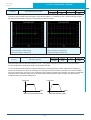
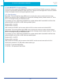
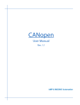
□ 60mm Torque curves
300
J0200-301-4-000
2.8A
J0200-301-4-000
8.4A
250
torque, oz-in
200
150
100
50
0
0
1000
2000
3000
4000
5000
6000
7000
8000
speed, rpm
300
SV2B3 and SV2B3
J0200-302-4
1.4A
J0200-302-4
4.2A
250
torque, oz-in
200
150
100
50
0
0
1000
2000
3000
4000
speed, rpm
19
5000
6000
7000
8000
920-0096B
9/1/2015
SV200 Hardware Manual
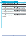
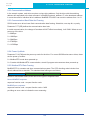
□ 60mm Torque curves
500
J0400-301-4-000
5.4A
450
J0400-301-4-000
13.5A
400
torque, oz-in
350
300
250
200
150
100
50
0
0
1000
2000
3000
4000
5000
6000
7000
8000
speed, rpm
600
SV2B3 and SV2B5
J0400-302-4
2.7A
J0400-302-4
8.1A
500
torque, oz-in
400
300
200
100
0
0
1000
2000
3000
2.3.3.3 □80mm Specification and Dimension
4000
speed, rpm
20
5000
6000
7000
8000
920-0096B
9/1/2015
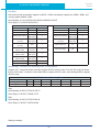
SV200 Hardware Manual
□ 80mm Series
UL File
E465363
Insulation Class
Class B(130°C)
IP rating
IP65(except shaft through hole and cable end
connetor)
Installation location
Indoors, free from direct sunlight, corrosive gas,
inflammable gas
Ambient temperature
Operating 0 to 40°C, Storage -20 to 80°C
Ambient humidity
85%RH or lower (free from condensing)
Altitude (maximum)
Operating 1,000m
Vibration Resistance
49 m/s2
Rotor Poles
8
□ 80mm Series
Series
J0750 - 750 Watt
Base Model Number
(with 2500 PPR incremental encoder non-sealed plastic
connectors, no brake)
Rated Output Power
watts
J0750-302-5-000
750
Rated Speed
rpm
3000
Max. Mechanical Speed
rpm
5500
Rated Torque
Nm
2.4
Continuous Stall Torque
Nm
2.6
Peak Torque
Nm
6.9
Rated Current
A (rms)
4.5
Continuous Stall Current
A (rms)
4.9
Peak Current
A (rms)
13.5
V (rms) / K rpm
36.6
Voltage Constant ±5%
Torque Constant ±5%
Nm / A (rms)
0.543
Winding Resistance (Line-Line)
Ohm ±10% @25°C
1.47
Winding Inductance (Line-Line)
mH
8.2
Inertia (with encoder)
kg m^2
0.89 X 10⁻⁴
Inertia - With Brake Option
kg m^2
0.97 X 10⁻⁴
Thermal Resistance (mounted)
°C / W
1.04
Minutes
22
Thermal Time Constant
mm
240 x 240 x 6 Aluminum
Shaft Load - Axial
Heat Sink Size
(max.)
90 N / 20 Lb
Shaft Load - Radial (End of Shaft)
(max.)
270 N / 60 Lb
Weight (with std. encoder)
2.6 kg / 5.8 lb
Weight - With Brake Option
3.4 kg / 7.6 lb
Shaft Load: (L10 life, 20,000 hours, 2,000 RPM)
80mm Series
21
920-0096B
9/1/2015
SV200 Hardware Manual
80mm Dimensions
1 Motor Dimensions – No Brake: mm
0
30
±5
0
0
30
±5
0.04 A
0
4-
0
- 0.013
6.5
45°
19 h6
10
M5
0
70 h7 - 0.03
0.04 A
94
0
- 0.03
A
-KEY
90
3 ±0.2
+0.300
9.5
21.5 - 0.118
40 ±1
Without Brake
J0750-302-5
6 h9
Oil seal
80
L1 ±1
L1
131
2 Motor Dimensions – Brake: mm
0.04 A
0
±5
0
±5
50
0
0±
30
30
30
0
M5
0
70 h7 - 0.03
0.04 A
0
- 0.013
6.5
45°
19 h6
4-
10
94
3 ±0.2
40 ±1
With Brake
J0750-352-5
0
- 0.03
Oil seal
6 h9
A
-KEY
90
+0.300
21.5 - 0.118
9.5
80
L1 ±1
L1
178
22
920-0096B
9/1/2015
SV200 Hardware Manual
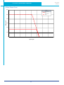
□ 80mm Torque Curve
1200
SV2B5
J0750-302-5
4.5A
J0750-302-5
13.5A
1000
torque, oz-in
800
600
400
200
0
0
1000
2000
3000
4000
speed, rpm
23
5000
6000
7000
8000
920-0096B
9/1/2015
SV200 Hardware Manual
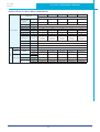
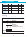
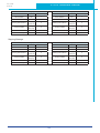
2.4 Servo Drive and Servo Motor Combinations
50W
Specificatioon
100W
200W
400W
750W
Motor Model Numbers
AC Servo Motor
2500ppr Increment
Encoder
(14PIN AMP connector)
Without Brake
J0050-302-3-000
J0100-302-3-000
J0200-302-4-000
J0400-302-4-000
J0750-302-5-000
With Brake
J0050-352-3-000
J0100-352-3-000
J0200-352-4-000
J0400-352-4-000
J0750-352-5-000
Rated Speed
(RPM)
Maximum Speed
(RPM)
Maximum Torque
(N•m)
0.19
0.32
0.64
1.27
2.4
Maximum Torque
(N•m)
0.48
0.93
1.9
3.8
6.9
3000
6000
Rated Current
(A)
0.7
1.2
1.5
2.75
4.5
Maximum Current
(A)
1.75
3.6
4.5
8.3
13.5
Rotor Inertia
Kg•m2
0.0232×10-4
*0.0298×10-4
0.0428×10-4
*0.0494×10-4
0.165×10-4
*0.22×10-4
0.272×10-4
*0.326×10-4
0.89×10-4
*0.97×10-4
(*With Brake)
(*With Brake)
(*With Brake)
(*With Brake)
(*With Brake)
Insulation Class
Class B
Protection Class
IP65(except shaft through hole and cable end connetor)
Oil Seal
With Oil seal
Drive Model Numbers
Pulse&Direction
Type
AC
Servo
Drive
Basic Type
SV2B2-P-NE
SV2B2-P-NE
SV2B2-P-NE
SV2B3-P-NE
SV2B5-P-NE
Q Type
SV2B2-Q-AE
SV2B2-Q-AE
SV2B2-Q-AE
SV2B3-Q-AE
SV2B5-Q-AE
SV2B2-Q-RE
SV2B2-Q-RE
SV2B2-Q-RE
SV2B3-Q-RE
SV2B5-Q-RE
USB Mini
SCL
RS-485
Modbus RTU
Fieldbus Type
CAN
CANopen
SV2B2-C-CE
SV2B2-C-CE
SV2B2-C-CE
SV2B3-C-CE
SV2B5-C-CE
Ethernet/IP
SV2B2-IP-EE
SV2B2-IP-EE
SV2B2-IP-EE
SV2B3-IP-EE
SV2B5-IP-EE
eSCL
SV2B2-Q-EE
SV2B2-Q-EE
SV2B2-Q-EE
SV2B3-Q-EE
SV2B5-Q-EE
Ethernet
24
920-0096B
9/1/2015
SV200 Hardware Manual
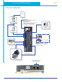
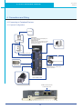
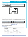
2.5 System Configuration
AC Power
LED Display
The 5 digit,7 segment LED displays the
driver status and faults.
Operation Panel
Function keys are used to perform status
display,monitoring and diagnostic
functions and parameter setting.
Non Fuse Breaker
USB communication Port
(CN1)
Electromagnetic
Contactor
Main Power Input
Control Power Input
PLC
Motion Control Card
Regen
Resistor
Motor Power Cable
I/O Interface
Used to connect PLC ,motion card
and other controllers.
Motor Feedback Cable
CANBus, RS-485, Ethernet
Communication Port
25
920-0096B
9/1/2015
SV200 Hardware Manual
3.Installation
3.1 Storage Conditions
•
Store within an ambient temperature range of -20°C to +65°C.
•
Store within a relative humidity range of 10% to 85% and non-condensing
•
DO NOT store in a place subjected to corrosive gasses
3.2 Installation Conditions
•
Temperature range of 0°C to 40°C. If the ambient temperature of servo drive is greater than 40°C,
please install the drive in a well-ventilated location.
The ambient temperature of servo drive for long-term reliability should be under 40°C.
•
The servo drive and motor will generate heat. If they are installed in a control panel, please
ensure sufficient space around the units for heat dissipation.
•
Operation within a relative humidity range of 10% to 85% and non-condensing
•
Watch for a vibration level lower than 6m/s2, 10Hz-60Hz.
•
DO NOT mount the servo drive and motor in a location subjected to corrosive gasses or flammable
gases, and combustibles.
•
Mount the servo drive to an indoor electric control cabinet.
•
DO NOT mount the servo drive in a location subjected to airborne dust.
26
920-0096B
9/1/2015
SV200 Hardware Manual
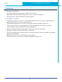
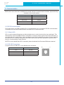
3.4 Installation Space
•
Incorrect installation may result in a drive malfunction or premature failure of the drive and or motor.
Please follow the guidelines in this manual when installing the servo drive and motor.
•
The SV200 servo drive should be mounted perpendicular to the wall or in the control panel.
•
In order to ensure the drive is well ventilated, ensure that the all ventilation holes are not obstructed
and sufficient free space is given to the servo drive.
•
Please ensure grounding wires are securely connected
100mm
20mm
Fan
Fan
10mm
10mm
10mm
20mm
10mm
10mm
10mm
20mm
80mm
20mm
100mm
27
920-0096B
9/1/2015
SV200 Hardware Manual
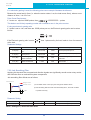
3.5 Motor Installation
• DO NOT strike the motor when mounting as the motor shaft or encoder may be damaged.
• DO NOT use cables soaked in water or oil.
• Avoid excess cable stress at the cable outlets.
• Use flexible cables when using cable carrier, make sure the minimum cable bending diameter is
100mm.
• The shaft through-hole and cable end connector are not IP65.
28
920-0096B
9/1/2015
SV200 Hardware Manual
4. Connections and Wiring
4.1 Connecting to Peripheral Devices
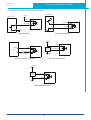
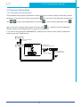
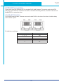
4.1.1 System Configuration
AC Power
LED Display
The 5 digit,7 segment LED displays the
diver status and faults.
Operation Panel
Function keys are used to perform status
display,monitor and diagnostic,function
and parameter setting.
Non Fuse Breaker
USB communication Port
(CN1)
Electromagnetic
Contactor
Main Power Input
Control Power Input
PLC
Motion Control Card
Regeneration
Absorbing Resistor
Motor Power Cable
I/O Interface
Used to connect PLC ,motion card
and other controllers.
Motor Feedback Cable
CANBus, RS-485, Ethernet
Communication Port
29
920-0096B
9/1/2015
SV200 Hardware Manual
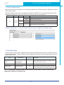
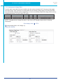
4.1.2 Servo Drive Connectors and Terminals
Terminal Identification
P1
Description
L1, L2, L3
L1C, L2C
U, V, W
P2
B1+, B2, B3
Regenerative resistor terninals
CN1
CN2
CN3
CN4
CN5
CN6
CN7
Communication Port
I/O Connector
Encoder Feedback Connector
Reserved
Reserved
RS-485/CANopen
*RS-232 Communication Port
RS-485/CANopen
Communication Port
Details
Used to connect three-phase AC main circuit power
Used to connect single-phase AC for control circuit power
Used to connect servo motor
Terminal
Wire color
Description
Symbol
U
Red
Connecting to three-phase
V
Yellow
motor main circuit cable
W
Blue
Internal
Ensure the circuit is closed between B2 and B3,
Resistor
and the circuit is open between B1+ and B3.
Ensure the circuit is open between B2 and B3,
External
and connect the external regenerative resistor
Resistor
between B1+ and B2.
User to connect personal computer
Used to connect external controllers.
Used to connect encoder of servo motor.
RJ45 connector, Daisy Chain, Used for RS-485/CANopen
*RS-232 Communication Port (-Q Type Only)
RJ45 connector, Daisy Chain, Used for RS-485/CANopen
Communication
4.1.3 Connections and Wiring Notes
• Ensure grounding wires are securely connected, 14 AWG wire is recommended.
• Grounding method must be single-point grounding.
• Ensure L1/L2/L3 and L1C/L2C are correctly wired, and voltage supplies are within the specification
range.
• Ensure U/V/W is following the order of RED/YELLOW/BLUE.
• Setup emergency stop circuitry to switch off the power supply when fault occurs.
• DO NOT touch drive or motor’s connector terminals 5 minutes after drive and motor is powered off.
Large capacitors within the unit will be discharged slowly.
• Install the encoder cables in a separate conduit from the motor power cables to avoid signal noise.
Separate the conduits by 30cm (11.8inches).
• Use stranded twisted-pair wires or multi-core shielded-pair wires for encoder feedback cables.
• The maximum length of encoder (PG) feedback cables is 15 meters.
30
920-0096B
9/1/2015
SV200 Hardware Manual
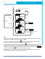
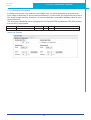
4.1.4 Wiring Methods For Power supply P1
220V AC servo drive supports single phase or three phase wiring method. Three phase wiring method for
750W or above drives is recommended.
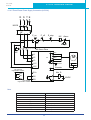
4.1.4.1 Single-Phase Power Supply Connection (AC220V)
L
N
E
MCCB
NF
E_stop
P_off
P_on
MC Alarm
MC
Alm_R
M2 Servo Drive
MC
L1C
L2C
P1
U
V
P2
W
Red
Yellow
Yellow/Green
L1
L2
CN3
B1+
Encoder
B2
B2
B3
Encoder
Ground
Use external
regeneration resistor
B1+
M
Blue
Alm_R
B3
Use Internal
24VDC
regeneration resistor
Note:
Symbol
Description
MCCB
Circuit Breaker
NF
Noise Filter
P_on
Power On Switch
P_off
Power Off Switch
E_stop
Emergency Stop Switch
MC
Magnetic Contactor
Alm_R
Alarm Relay
Alarm
Alarm Relay Contactor
31
920-0096B
9/1/2015
SV200 Hardware Manual
4.1.4.2 Three-Phase Power Supply Connection (AC220V)
R S T E
MCCB
NF
P_on
P_off
E_stop
MC
MC
Alarm
Alm_R
M2 Servo Drive
MC
U
L1
P2
L2
V
W
Red
Yellow
Yellow/Green
L3
Ground
L1C
L2C
CN3
Use external
regeneration resistor
Encoder
Encoder
Alm_R
B1+
B1+
M
Blue
B2
B2
B3
Use Internal
regeneration resistor
24VDC
B3
Note:
Symbol
Description
MCCB
Circuit Breaker
NF
Noise Filter
P_on
Power On Switch
P_off
Power Off Switch
E_stop
Emergency Stop Switch
MC
Magnetic Contactor
Alm_R
Alarm Relay
Alarm
Alarm Relay Contactor
32
920-0096B
9/1/2015
SV200 Hardware Manual
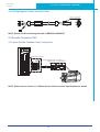
4.2 Wiring to the Connector P2
4.2.1 Motor Power Cable Configuration
P2 interface of the drive
Connector of Motor Power Connector of
extension cable the motor lead wire
PIN
1
2
3
4
Signal
U
V
W
PE
Color
Red
Yellow
Blue
Yellow/Green
NOTE: Please refer to section 4.2.2 Motor Power Cable Connector Specifications for details
4.2.2 Motor Power Cable Connector Specifications
◆ PIN Assignment
A
B
Vew A
Vew B
Type
Motor Side(Plug)
Plug-in(Housing)
Housing
AMP 172167-1
AMP 172159-1
Terminal
AMP 170360-1
AMP 170362-1
◆ Model of Motor Connector
Drive Side(P2)
(JST) S06B-F32SK-GGXR
4
Signal
Color
U
Red
Motor Side(Housing)
AMP 172159-1
1
5
V
Yellow
2
6
W
Blue
3
Grounding Screw
PE
Yellow/Green
4
33
920-0096B
9/1/2015
SV200 Hardware Manual
4.2.3 Wiring Diagram Of Motor Extension Cable
Housing: 172159-1(AMP)
Terminal: 170362-1(AMP)
NOTE: Ensure U/V/W is following the order of RED/YELLOW/BLUE.
4.3 Encoder Connector CN3
4.3.1 Motor Encoder Feedback Cable Configuration
P2 interface of the drive
Connector of Motor Power Connector of
extension cable the motor lead wire
NOTE: Please refer to section 4.1.5.2 Motor Power Cable Connector Specifications for details
34
920-0096B
9/1/2015
SV200 Hardware Manual
4.3.2 The Layout of CN3 Connector
2
14
1
15
12
13
25
1
A
B
14
26
View B
26
13
View A
Pin NO.
Symbol
Description
1
A+
Encoder A+
2
B+
Encoder B+
3
Z+
Encoder Z+
4
U+
Hall U+
5
W+
Hall W+
6
U-
Hall U-
7
W-
Hall W-
11
Encoder +5V
Encoder power supply +5V
13
Encoder +5V
Encoder power supply +5V
14
A-
Encoder A-
15
B-
Encoder B-
16
Z-
Encoder Z-
17
V+
Hall V+
19
V-
Hall V-
24
GND
Encoder power supply ground
26
Shield
Shield
35
920-0096B
9/1/2015
SV200 Hardware Manual
4.3.3 Connect to Motor Encoder
Connect to 2500ppr Increment Encoder (15PIN AMP connector)
Servo Drive CN3
CN3
9
10
11
12
13
14
3
Motor Encoder
4
5
6
7
8
1
2
15
A+
A+
A-
A-
B+
B+
B-
B-
Z+
Z+
Z-
Z-
U+
U+
U-
U-
V+
V+
V-
V-
W+
W+
W-
W-
+5V
+5V
GND
GND
Shield
Shield
1
14
2
15
3
16
4
6
17
19
5
7
11
24
26
4.3.4 Specifications of Encoder Connector
15PIN AMP Connector
A
◆◆
◆◆
◆◆ PIN Assignment
B
View A
View B
PIN#
Signal
Colour
1
+5V
Red
2
GND
Black
3
U+
Brown
4
U-
Brown/Black
5
V+
Gray
6
V-
Gray/Black
7
W+
White
8
W-
White/Black
9
A+
Blue/Black
10
A-
Blue
11
B+
Green
12
B-
Green/Black
13
Z+
Yellow
14
Z-
Yellow/Black
15
Shield
Shield
36
920-0096B
9/1/2015
SV200 Hardware Manual
Specifications of 15PIN AMP Connector
Type
Plug of the Motor
Housing for the motor
Housing
AMP 172171-1
AMP 172163-1
Terminal
AMP 770835-1
AMP 770834-1
4.3.5 Wiring Diagram of Motor Encoder Extend Cable
B. Diagram of 15PIN Encoder Cable
Connect to drive
Connect to Motor
Drive Side
3M 26PIN PIN
11
11
1
15
5
Housing for the motor
Signal
Colour
+5V
Red
AMP 172163-1
1
24
GND
Black
2
4
U+
Brown
3
6
U-
Brown/Black
4
17
V+
Gray
5
19
V-
Gray/Black
6
5
W+
White
7
7
W-
White/Black
8
1
A+
Blue/Black
9
14
A-
Blue
10
2
B+
Green
11
15
B-
Green/Black
12
3
Z+
Yellow
13
16
Z-
Yellow/Black
14
26
Shield
Shield
15
37
920-0096B
9/1/2015
SV200 Hardware Manual
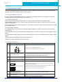
4.4 Electromagnetic Brake
When motor drives a vertical axis, a brake should be used to prevent the load from falling by gravity when
power is removed.
NOTE: Only use servo motor brake for holding when motor is disabled or AC is off.
4.4.1 Wiring Diagram
Servo Drive
Relay
Brake+
Relay
R
24VDC
Brake-
Brake
24VDC
4.4.2 Brake Motor
When no power is applied to the electromagnetic brake, it is in locked position. Therefore, the motor shaft
will not be able to rotate.
The brake coil has no polarity.
During the brake/release action, you might hear a clicking sound. This is normal..
Specification of brakes are as follows:
Motor Power
Type
50W
100W
200W
400W
750W
Holding Torque (Nm)
0.35
2
4.5
Coil Current (A)
0.25
0.38
0.61
Rated Voltage (V)
24V±10%
Release Time
<25ms
Engage Time
<25ms
Release Voltage (V)
Release Voltage18.5VDC
38
920-0096B
9/1/2015
SV200 Hardware Manual
4.4.3 Timing Charts Of The Electromagnetic Brake
In order to prevent damage to the brake, there are delay sequences during the brake operation.
ON
Servo-on In Put
OFF
ON
Motor Active
OFF
ON
Brake Signal
OFF
ON
Brake Action
OFF
ON
Motion Command
OFF
ON
Actual Motion
OFF
Brake Release Delay
P-68 Setting
Brake Engage Delay
P-69 Setting
Brake engage/disengage delay time can be set via SVX ServoSUITE®, or on the drive directly via P
function: P-69 (BD) or P-70 (BE).
39
920-0096B
9/1/2015
SV200 Hardware Manual
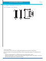
4.5 Regenerative Resistor
In SV200 series AC servo drives, there is a pre-installed 40W (SV2x5 model: 60W) regeneration resistor.
In some applications, the pre-installed regeneration resistor may be insufficient to absorb the regenerative
energy. In these cases, a larger wattage regeneration resistor needs to be connected externally.
Ensure the circuit is opened between
B2 and B3,and connect regenerative
resistor between B1+ and B2 when
using external resistor.
Ensure the circuit is closed between B2 and
B3,and the circuit is open between B1+ and
B3 when using internal resistor.
Regeneration
Resistor
4.6 Recommended Cable Specifications
• For the drive’s main circuit, please use wires rated at least 600VAC.
• Recommended wire selections are as follows:
Servo Drive And Coresponding Motor Model
J0050-3XX-X-XXX
SV2x2
J0100-3XX-X-XXX
J0200-3XX-X-XXX
SV3x3
J0400-3XX-X-XXX
SV2x5
J0750-3XX-X-XXX
Wire Width mmS (AWG)
L1/L2/L3
1.25
(AWG16)
1.25
(AWG16)
1.25
(AWG16)
2.0
(AWG14)
3.5
(AWG12)
L1C/L2C
1.25
(AWG16)
1.25
(AWG16)
1.25
(AWG16)
2.0
(AWG14)
3.5
(AWG12)
U/V/W
1.25
(AWG16)
1.25
(AWG16)
1.25
(AWG16)
2.0
(AWG14)
3.5
(AWG12)
B1+,B3
2.0
(AWG14)
2.0
(AWG14)
2.0
(AWG14)
2.0
(AWG14)
3.5
(AWG12)
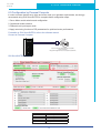
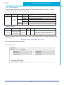
4.7 Connect to Host Computer,CN1
Port CN1 is used to connect drive with PC. Use SVX ServoSUITE® software to set control mode, change
parameter values, and use auto-tuning function and so on.
PIN
Symbol
Function
1
+5V
+5V Power Supply
2
D-
Data -
3
D+
Data +
4
—
Reserved
5
GND
Ground
40
SV200 Hardware Manual
920-0096B
9/1/2015
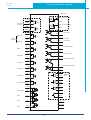
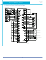
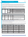
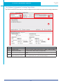
4.8 Input and Output Signal Interface Connector,CN2
4.8.1 Input and Output Interface Specifications and Diagram
Port CN2 on SV200 series AC servo drives is used for input/output signals. Details are shown in table
below:
Inputs
Digital Signal
Outputs
I/O
Signals
Analog Signal
8 Configurable Optically isolated general Inputs, 5-24VDC, 20mA
4 Configurable Optically isolated High Speed inputs
4 Configurable Optically isolated general Outputs, max 30VDC, 20mA
1 Alarm Output, max 30VDC, 20mA.
1 motor brake control output, max 30VDC, 100mA .
Inputs
2 Analog Inputs, with 12bit resolution
Inputs
2 Optically isolated high speed inputs 500Hz (Open collector)
2 high speed differential inputs 2MHz
Pulse Signal
Outputs
4 high speed encoder feedback output (3 Line Driver A/B/Z, and 1 open collector
output Z)
41
920-0096B
9/1/2015
SV200 Hardware Manual
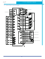
Analog Input
+
-
PULSH1 44
16
15
High Speed
Pulse Input
ANA1 Speed Command
DGND
PULSH2 45
+
-
SIGNH1 46
18
17
SIGNH2 47
X1+
3
X1-
4
X2+
5
X2-
6
X3+
29
ANA2 Torque Command
DGND
37 Y1+
Alarm Output
36 Y1-
STEP+/CW
Position
Command
11
10
DIR/CCW
Y2+
Motor Brake
Control Output
Y2-
40 Y5+
Servo Ready Output
41 Y5-
Enable
X3-
X4+
31
14
Y6+
13
Y6-
35
In Position Output
Alarm Reset
X4-
34
X5+
8
X5-
2
X6+
9
X6-
1
X7+
39
X7-
38
X8+
12
Control mode Switch
X8-
32
42 Y3
Torque Reached Output
Limit Sensor
43 Y4
Limit Sensor
Gain Select
Velocity Reached Output
33 OUT21 AOUT+
22 AOUT48 BOUT+
49 BOUT23 ZOUT+
COM 7
1.5K
24 ZOUTDividing Switch
X9
26
1.5K
19 CZ
1.5K
SPD0
X10
27
1.5K
15 DGND
1.5K
SPD1
X11
28
1.5K
20 +10V User
1.5K
25 User_GND
SPD2
X12
30
1.5K
50 FG
42
Encoder
Feedback
Output
920-0096B
9/1/2015
SV200 Hardware Manual
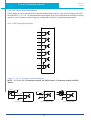
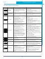
4.8.2 Signals Description of Connector CN2
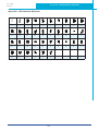
4.8.2.1 The Layout of CN2 Connector
A
26
1
2
24
B
1
27
26
50
25
49
B视图
50
25
A视图
4.8.2.2 Input Signals
SV200 series AC servo drive has 12 configurable digital inputs as well as 2 analog inputs.
Each of the inputs can be specified with different function via parameter settings. The functions are as
follows:
• Specified function signals: i.e. STEP/DIR signal, motor enable/disable signals.
• General purpose signal: In velocity mode, torque mode, Q program mode, or SCL mode, it is used as
general purpose signal with no specified functions:
43
920-0096B
9/1/2015
SV200 Hardware Manual
Signal
Symbol
Pin NO.
X1+
3
X1-
4
X2+
5
X2-
6
X3+
X3X4+
X4X5+
X5X6+
X6X7+
X7X8+
X8-
29
31
35
34
8
2
9
1
39
38
12
32
X9
X9
26
X10
X10
27
X11
X11
28
X12
X12
30
● Pulse Inhibited Input. Ignore the pulse input when this input is activated
in position mode.
● Speed Selecting Input 1 in change Speed mode.
● General purpose input.
● Speed Selecting Input 2 in change Speed mode.
● General purpose input.
● Speed Selecting Input 3 in change Speed mode.
● General purpose input.
COM
COM
7
X9-X12 COM point.
PULSH1
PULSH2
SIGNH1
44
45
46
SIGNH2
47
High-speed pulse inputs (+5VDC line drive input).The max. input
frequency is 2MHz.Three different pulse command can be selected:
● Pulse & Direction
● CW Pulse and CCW Pulse
● A Quadrature B pulse
(NOTE: DO NOT use it with X1/X2 both. )
X1
X2
X3
X4
X5
X6
X7
X8
High-Speed
Pulse
Inputs
Analog
Input Signal
1
Analog
Input Signal
2
Details
This input has three functions:
● Accept STEP pulse input such as STEP signals, CW pulse, A pulse in
Position mode.
● Run/Stop input in torque or velocity mode.
● General purpose input.
This input has three functions:
● Accept STEP pulse input such as Direction signals, CCW pulse,
B pulse in position mode.
● Direction input in torque or velocity mode.
● General purpose input.
● Enable/Disable input.
● General purpose input.
● Alarm Reset Input, used to reset drive alarm.
● General purpose input.
● Limit Sensor Input.
● General purpose input.
● Limit Sensor Input.
● General purpose input.
● Gain Select Input in all control mode.
● General purpose input.
● Switch Control mode between main mode and second mode.
● General purpose input.
● Dividing Switch, change the pulses per revolution for electronic
Gearing.
● General purpose input.
ANA1
16
● In velocity command mode in analog velocity mode. The offset ,dead
band, function of analog input 1 can be set by SVX ServoSUITE® or
parameters P-51, P-55 and P-60.
● Sets or requests the analog Input gain that relates to motor position
when the drive is in analog position command mode.
● Sets or requests the gain value used in analog velocity mode.
● General Analog Input in Q mode.
DGND
15
Digital Ground for Analog input.
ANA2
18
● In torque command mode in analog torque mode. The offset ,dead
band, function of analog input 2 can be set by SVX ServoSUITE® or
parameters P-53,P-57 and P-61.
● General Analog Input in Q mode
DGND
17
Digital Ground for Analog input.
44
920-0096B
9/1/2015
SV200 Hardware Manual
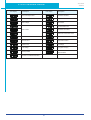
4.8.2.3 Inputs Function List
1
2
3
4
5
6
7
8
9
10
11
12
▲
▲
▲
●
●
■
Step
■
DIR
●
CW Limit
●
CCW Limit
▲▼
Start/Stop
▲▼
Direction
●
Servo enable
●
Alarm clear
Speed selection 1,2,3
■
Global gain selection
●
Control mode selection
Pulse encoder
Resolution selection
Pulse Inhibit
■
■
●
General Input
●
●
●
●
●
●
●
●
●
■– Position Mode ▲– Velocity Mode ▼ – Torque Mode ● – All Modes
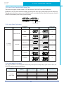
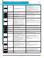
4.8.2.4 Output Signals
SV200 series AC servo drive has 6 programmable digital output signals available; each of the outputs can
be specified with different function via parameter settings.
Signal
Y1
Y2
Y3
Y4
Y5
Y6
Encoder pulse
feedback Output
+10V
Output
Symbol
Y1+
Pin NO.
37
Y1-
36
Y2+
11
Y2-
10
Y3+
Y3Y4+
42
33
43
Y4-
33
Y5+
40
Y5-
41
Y6+
14
Y6-
13
AOUT+
AOUTBOUT+
BOUTZOUT+
ZOUTZOUT
+10V User
USER_GND
21
22
48
49
23
24
19
20
25
Details
This output has two functions:
● Alarm
Output.
purpose output.
● General
This output has two functions:
● Motor
brake control output.
purpose output.
● General
● Torque
Reached Output.
purpose output.
● General
● Moving
signal output, output signal when dynamic position error less
than set value in position mode.
● Velocity Reached output. Output signal when actual speed is same as
the
target speed and the speed ripple less than ripple range.
● General purpose output.
● Servo
ready output. Output servo ready signal when the drive is ready
to be controlled and without alarm.
● General purpose output.
● In
position signal output, output signal when in position, and the
position error less than set value in position mode.
● Tach out output. Tach output, produces pulses relative to the motor
position with configurable resolution.
● General purpose output.
The encoder feedback phase A line drive output.
The encoder feedback phase B line drive output.
The encoder feedback phase Z line drive output.
The encoder feedback phase Z output. (Open collector)
+10VDC user ,max 100mA
+10VDC user Ground
45
920-0096B
9/1/2015
SV200 Hardware Manual
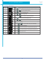
4.8.2.5 Outputs Function List
Output Pin
Y1
Y2
Y3
Y4
Y5
●
InPostion error
■
Dynamical Postion error
●
Tach Out
Function
Y6
●
Alarm Output
●
Brake
Torque Reached
●
●
Servo Ready
▲▼
Velocity Reached
●
General Output
●
●
●
●
■– Position Mode ▲– Velocity Mode ▼ – Torque Mode ● – All Modes
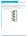
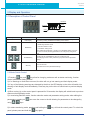
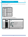
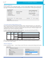
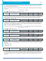
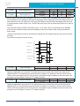
4.8.3 Input Signal Interface Connector CN2
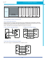
4.8.3.1 Position pulse signal input
SV200 series AC servo has two high speed pulse inputs, STEP/DIR and PULSH/SIGNH. STEP/DIR
supports 5-24VDC up to 500Hz open collector input signal or differential input signal through line driver.
PULSH/SIGNH supports 5VDC up to 2MHz with differential line driver input.
NOTE: STEP/DIR and PULSH/SIGNH CANNOT be used at the same time.
A. Open Collector Input Signal Diagram
B. Differential Input Signal Diagram
24VDC
controller
Controller
Differential Input
Open Collector input
PULSH1 44
STEP+ 3
PULSH2 45
STEP- 4
SIGNH1 46
5
DIR+
SIGNH2 47
DIR- 6
DGND
DGND 25
50
FG
0VDC
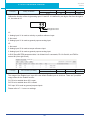
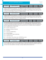
C.High Speed Differential Signal Input Diagram
ONLY use 5V supply for PULSH/SIGNH input, DO NOT use 24V.
Controller
Differential Input
PULSH1 44
PULSH2 45
SIGNH1 46
SIGNH2 47
DGND 25
DGND
50
FG
FG
46
FG
920-0096B
9/1/2015
SV200 Hardware Manual
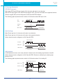
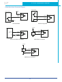
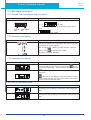
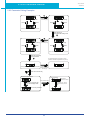
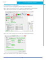
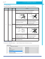
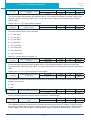
D. Pulse Input Description
STEP/DIR Pulse Input
When both STEP and DIR input signal is ON, the motor will rotate in one direction
When STEP input signal is ON, and DIR input signal is OFF, the motor will rotate in the opposite direction.
*Direction signal (DIR) can be configured via SVX ServoSUITE® software.
The following graph represents motor rotation in CW direction when DIR input is ON.
Single Pulse Input
Step
(PLS)
High
Low
Direction
(DIR.)
Low
Motor motion
High
CCW Direction
CW Direction
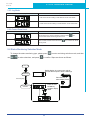
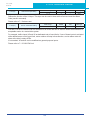
CW/CCW Pulse
When Pulse input into X1, the motor will rotate in one direction.
When Pulse input into X2, the motor will rotate in the opposite direction.
*Motor direction can be configured via SVX ServoSUITE®.
Dual Pulse Input
CW pulse
High
Low
CCW pulse
High
Low
CCW Direction
Motor motion
CW Direction
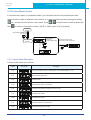
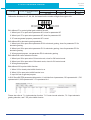
A/B Quadrature
In A/B Quadrature mode, motor rotary direction is based on the the leading signal between A and B.
*Motor direction can be configured via SVX ServoSUITE®. Direction is defined by the leading input
between X1/X2.
The following graph represents motor rotation in CW direction when X1 is leading X2.
A/B Quadrature Pulse Input
High
Input A(X1)
Input B(X2)
Low
High
Low
CCW Direction
Motor motion
CW Direction
47
920-0096B
9/1/2015
SV200 Hardware Manual
4.8.3.2 Analog Signal Input For Velocity And Torque Mode
SV200 series AC servo drive has 2 single ended analog inputs or 1 differential analog input. The input
voltage range is between -10V~+10V. Velocity and torque range can be configured via SVX ServoSUITE®
software.
A.Single Ended Analog Input
Single Ended Analog Control Mode
ANA1(ANA2) 16(18)
±10VDC
DGND
+
-
15(17)
B. Differential Analog Input
Host PC
Differential Analog Control Mode
16
+
-
15
D/A Output
18
17
DGND
DGND
48
+
-
SV200 Hardware Manual
920-0096B
9/1/2015
4.8.3.3 High Speed Input Port X1, X2, X3, X4
A. High Speed Input Port
SV200 series AC servo drive has 4 Optically isolated high speed digital inputs X1, X2, X3, X4.
These inputs allow input voltage from 5VDC~24VDC with maximum current of 20mA, and up
to 500KHz. They can be used for general purpose inputs, connecting sensor switch signals,
PLC controllers or other types of controller output signals.
NOTE: When drive is in position mode, X1, X2 can ONLY be set as STEP/DIR signal.
When drive is NOT in position mode, X1, X2 can be set as general purpose signals.
X1, X2, X3, X4 Circuits Are As Follows:
X1+
3
X1-
4
X2+
5
X2-
6
X3+
29
X3-
31
X4+
35
X4-
34
49
920-0096B
9/1/2015
SV200 Hardware Manual
B High Speed Input Connection Diagram
HOST controller
5-24VDC
HOST controller
5-24VDC
X1\2\3\4+
X1\2\3\4+
X1\2\3\4X1\2\3\40VDC
0VDC
Host Sink Mode
Host Sourcing Mode
5-24VDC
X1\2\3\4+
+5-24VDC
Power
0V
X1\2\3\4+
NPN
Output
sensor
connection
X1\2\3\4Relay Or Switch
X1\2\3\4-
0VDC
Sensor And Switch Connection
NPN Sensor Connection
5-24VDC
PNP
Output
sensor
connection
X1\2\3\4+
X1\2\3\40VDC
PNP Sensor Connection
50
SV200 Hardware Manual
920-0096B
9/1/2015
4.8.3.4 General Digital Input X5, X6, X7, X8
SV200 series AC servo drives have 4 Optically isolated general digital inputs X5, X6, X7, X8. Input
voltage range is 5VDC-24VDC, with maximum input current of 20mA up to 5KHz. Both single-ended and
differential signals are allowed.
X5, X6, X7, X8 Circuits Are As Follows:
X5+
8
X5-
2
X6+
9
X6-
1
X7+
39
X7-
38
X8+
12
X8-
32
51
920-0096B
9/1/2015
SV200 Hardware Manual
X5, X6, X7, X8 Input Port Connection Diagram
HOST controller
5-24VDC
HOST controller
5-24VDC
X5\6\7\8+
X5\6\7\8+
X5\6\7\8-
X5\6\7\80VDC
0VDC
Host Sink Mode
Host Sourcing Mode
5-24VDC
X5\6\7\8+
+5-24VDC
Power
0V
X5\6\7\8+
NPN
Output
sensor
connection
X5\6\7\8Relay Or Switch
X5\6\7\8-
0VDC
NPN Sensor Connection
Sensor And Switch Connection
5-24VDC
PNP
Output
sensor
connection
X5\6\7\8+
X5\6\7\80VDC
PNP Sensor Connection
52
920-0096B
9/1/2015
SV200 Hardware Manual
4.8.3.5 X9, X10, X11, X12 Input With Common Com Port
SV200 series AC drives also have 4 single ended optically isolated inputs that share a single common
node ‘COM’. They can be used with sourcing or sinking signals, 5-24V, allowing connections to PLCs,
sensors, relays and mechanical switches. Because the input circuits are isolated, they require a source of
power. If you are connecting to a PLC, you should be able to get power from the PLC power supply. If you
are using relays or mechanical switches, you will need a 5-24 V power supply.
What is COM?
“Common” is an electronics term for an electrical connection to a common voltage. Sometimes “common”
means the same thing as “ground”, but not always. If you are using sinking (NPN) signals, then COM
must connect to power supply +. If you are using sourcing (PNP) input signals, then you will want to
connect COM to ground (power supply -).
NOTE: If current is flowing into or out of an input, the logic state of that input is low or closed. If no current
is flowing, or the input is not connected, the logic state is high or open.
X9, X10, X11, X12 Circuits Are As Follows:
COM
7
1.5K
X9
26
1.5K
1.5K
X10
27
1.5K
1.5K
X11
28
1.5K
1.5K
X12
30
53
1.5K
920-0096B
9/1/2015
SV200 Hardware Manual
X9, X10, X11, X12 Input Port Connection Diagram
HOST controller
5-24VDC
HOST controller
COM
5-24VDC
1.5K
X9\10\11\12X9\10\11\12-
COM
0VDC
0VDC
Host Sink Mode
Host Sourcing Mode
5-24VDC
COM
+5-24VDC
Power
0V
COM
X9\10\11\12-
1.5K
1.5K
1.5K
NPN
Output X9\10\11\12sensor
connection
1.5K
1.5K
1.5K
0VDC
Relay Or Switch
Sensor And Switch Connection
NPN Sensor Connection
5-24VDC
PNP
Output X9\10\11\12sensor
connection
COM
1.5K
1.5K
0VDC
PNP Sensor Connection
54
1.5K
920-0096B
9/1/2015
SV200 Hardware Manual
4.8.4 CN2 Output Signal Specification
SV200 series AC servo drives feature 6 optically isolated digital outputs. They can be configured via SVX
ServoSUITE®. Y1, Y2, Y5, Y6 are differential output signals, they can be used for both sourcing or sinking
signals. Y3 and Y4 share a common ground, making them useful for connecting sinking signals.
4.8.4.1 CN2 Output Signal Diagram
Y1+
37
Y1-
36
Y2+
11
Y2-
10
Y5+
40
Y5-
41
Y6+
14
Y6-
13
Y3
42
Y4
43
OUT-
4.8.4.2 Y1, Y2, Y5, Y6 Output Connection Diagram
NOTE: Y1、Y3、Y4、Y5、Y6 maximum outputs are 30VDC 30mA. Y2 maximum output is 30VDC,
100mA.
Controller
24VDC
24VDC
COM
24VDC
Y1/2/5/6+
IN
Y1/2/5/6+
Y1/2/5/6+
Relay
Y1/2/5/6-
Y1/2/5/6-
Y1/2/5/60VDC
0VDC
0VDC
Opt Coupler Circuity
Connect To External Load
55
Connect To Relay Circuity
920-0096B
9/1/2015
SV200 Hardware Manual
4.8.4.3 Y3, Y4 Connection Examples
24VDC
42 Y3
43 Y4
33 OUT-
0VDC
4.8.5 Encoder Feedback Output
SV200 series AC servo drives can output encoder A/B/Z phases as differential output signals through a
line driver. The output signal is 5V, A/B signals are 10000 pulse/rev, Z signal is 1 pulse/rev.
The host must use a line receiver to receive the signals. Use twisted pair wires for signal transfer.
4.8.5.1 A/B/Z Connection Diagram
Servo Drive
Host Controller
21 AOUT+
A+
22 AOUT-
A-
48 BOUT+
B+
49 BOUT-
B-
23 ZOUT+
Z+
24 ZOUT-
Z-
25 DGND
DGND
50
FG
FG
NOTE: Please make sure the host controller and the servo drive are connected to a common ground.
4.8.5.2 Z Phase Open Collector Output
The encoder index pulse signal Z uses open collector output circuitry. Due to the narrow bandwidth of the
index pulse, high speed optocoulper circuitry should be used for the host receiver.
24VDC
Servo Drive
19 CZ
15 DGND
0VDC
56
920-0096B
9/1/2015
SV200 Hardware Manual
5.Display and Operation
5.1 Description of Control Panel
LED Display
Set Key
Mode Key
M
S
Down Key
Up Key
Symbol
Name
Details
LED Display
The LCD display (5 digits, 7 segments) show the drive’s operating condition
and warning codes, parameters and setting shows values.
Press and hold on mode button to switch LED display mode
a). Monitoring selection mode
b). Function selection mode
MODE Key
c). Parameter setting mode
When editing the parameters, pressing on mode MODE button can move
the cursor to the left, allowing parameters to be changed by using arrow
keys.
UP/DOWN Key
SET Key
Pressing the UP and DOWN key allow for scrolling through
and changing monitor codes, parameter groups and various parameter
settings.
Press to set mode
Press and hold to save parameters/settings
5.2 Mode Switch Control
1) Pressing
key and
key allow for changing modes as well as status monitoring, function
control, parameters setting and etc.
2) If no warnings or faults have occurred, the drive will not go into warning and fault display mode.
3) If any of the following warnings are detected by the drive, the LED display on the drive will switch into
warning or fault display mode immediately. Press any key on the drive to switch back to previous display
mode.
4) When no key (s) on the control panel is pressed for 20 seconds, the display will switch back to previous
status monitoring display mode.
5) In monitoring selection mode, function selection mode and parameter setting mode, when editing the
parameters, pressing on
using
can move the cursor to the left allowing for parameters to be changed by
keys.
6) In status monitoring mode, pressing and holding the
panel, please press and hold the
key again.
57
key, will lock the control panel. To unlock the
920-0096B
9/1/2015
SV200 Hardware Manual
Control mode switch flowchart:
Power On
In factory default mode, it will display motor’s rotatory velocity.(*NOTE 1)
The last dot shows whether the drive is enable or disable.
Monitor Status
Press SET key back
to Monitor Status
Press any key
S
Monitor Parameters
Press and hold the
MODE key for 1 second
Press the UP and
DOWN key to scroll
through and change
monitor status
M
Press and hold the
MODE key for 1 second
Function Parameters
Press and hold SET key to
confirm selection and execute it.
M
Press and hold the MODE
key for 1 second(*NOTE 4)
Press the UP and
DOWN key to scroll
through and change
function selection
S
M
Drive Parameters
Configuration
Press the UP and
DOWN key to scroll
through and change
parameter selection.
Press SET key enter
to value setting mode
S
Press SET key back to
Drive Parameters Configuration
mode without changing.
*NOTE(2)
Press and hold for 1 second
the SET key to confirm setting value
*Note(3)
S
NOTE:
1) When power is applied, drive’s display will show customer defined monitoring mode. In factory
default mode, it will display motor’s rotary velocity in RPM.
2) In parameter setting mode, pressing the
key will quit from parameter setting mode, and
return back to parameter selection mode (changes will not be saved).
3) In parameter setting mode, pressing and holding the
button will confirm and apply current
parameter setting. This will take effect immediately. However, this change will not save to drive’s
flash memory. If parameter is required for permanent use, please go to function mode“
”, and then press and hold
button to save the parameter change.
4) When drive is connected to the host computer with SVX ServoSUITE® on, parameter setting
mode CANNOT be accessed directly on drive’s control panel.
58
920-0096B
9/1/2015
SV200 Hardware Manual
5.3 LED display description
5.3.1 Decimal Point And Negative Sign Description
LED display
Description
Negative sign: when display value ≥-9999, the highest digit will show
as ‘-’. i.e.
negative motor enable
sign
sign
, as ‘-9999’
When display value≤-10000, the negative sign will not be
shown,
, as “-10000”
5.3.2 Parameter View Setting
LED display
Description
There are only 5 digits on the LED display, when more than 5 digits
are needed, it will show as following:
When the highest digit is flashing, it means the lower 5 digits are
showing. Press
to show the upper 5 digits.
The graphic is showing ‘-12802345’
5.3.3 Parameter Save Setting
LED display
Description
In parameter setting mode, pressing and holding the
key will
save the parameter change. ‘Saved’ will also be shown on the LED
display.
In parameter setting mode when the motor is rotating, pressing and
holding the
, will cause the LED display to show status as busy, meaning
that the current parameter cannot be saved, stop the current motor
motion and save the parameter again.
5.3.4 Point To Point Motion Mode
LED display
Description
P-CW means motor is rotating in CW direction under point-to-point
mode
P-CCW means motor is rotating in CCW direction under point-to-point
mode
59
920-0096B
9/1/2015
SV200 Hardware Manual
5.3.5 Jog Mode
LED display
Description
J—CW means motor rotating in CW direction under JOG mode
J—CCW means motor rotating in CCW direction under JOG mode
5.3.6 Control Panel Lock
LED display
Description
This means the key panel is locked. Press and hold
second under status monitoring mode to lock.
When control is locked. Press and hold
the key panel.
for 1
for 1 second to unlock
5.4 Status Monitoring Selection Mode
To change the status monitoring type, please press
use
to make selections, and press
to enter monitoring selection mode, and then
to confirm. Steps are shown as follows:
Power ON
Default display is current motor velocity
The last decimal point is drive enable sign
Stats Display
Press SET key to
select display mode
Press Any Key
Press UP and
DOWN key
to select display
detail.
Status Monitoring
Selection
60
S
920-0096B
9/1/2015
SV200 Hardware Manual
N mode selection and setting
LED display
Description
Unit
n-00
Motor Rotating Speed
n-01
Position Error
counts
n-02
Pulse Counter
Pulse
n-03
Encoder Counter
counts
n-04
Command Position Counter
counts
n-05
Drive Temperature
x 0.1°C
n-06
DC Bus Voltage
n-07
Fault History 1
n-08
Fault History 2
n-09
Fault History 3
n-10
Fault History 4
n-11
Fault History 5
n-12
Fault History 6
n-13
Fault History 7
n-14
Fault History 8
61
RPM
x0.1V
920-0096B
9/1/2015
SV200 Hardware Manual
5.5 Function Mode Control
In function mode (display F+ parameter number), you can select functions for preoperational mode,
restart the drive, enable or disable the drive and so on. In status monitoring mode, pressing and holding
for 1 second will enter function control mode. Press
to select function, and then press and
to confirm or execute the function. (NOTE: F-00(FL) and F-01(CJ) excepted)
hold
Status display
selection
Press and Hold MODE key
for 1 second
M
Press UP and
DOWN key
to select display detail.
Function Mode
Selection
Press and Hold Set key to
select and execute the function
S
5.5.1 Function Mode Description
Function mode details are as follows:
Function mode
number
LED display
Description
F-00
point to point position mode:1) rotating speed: 1rps 2)travel distance: 1rev
F-01
JOG mode:JOG speed 1rps
F-02
Restart the drive
F-03
(F-03AR) Clear drive’s current alarm
F-04
(F-04SA) Save parameter changes for P-00 to P-98
F-05
(F-05MD) Drive disable
F-06
(F-06ME) Drive enable
F-07
(F-07MC) Select motor specification
F-08
(F-08AZ)Analog input auto-offset
62
920-0096B
9/1/2015
SV200 Hardware Manual
5.5.2 Operation Flow Chart :
status monitoring
selection
press and hold MODE key
for 1 second
M
press and hold
SET key
F-00 point to point mode
function selection
mode
press M key
press
,motor rotate
1 rev in CW direction
press
,motor rotate
1 rev in CCW direction
press S to stop the motor
press M to return back
NOTE: In P-P mode, rotary velocity is 1rps,
and 1 rev per time.
Press UP and DOWN key
to select display detail.
press and hold
SET key
F-01 JOG mode
S
M
press M key
NOTE: In JOG mode, rotary velocity is
1rps
Press UP and DOWN key
to select display detail.
press and hold
SET key
F-02 Restart the drive
press
,motor rotate
in CW direction
Press
,motor rotate
in CCW direction
press S stop motor
press M to return back
Drive restart, and back to status
monitoring mode
S
Press UP and DOWN key
to select display detail.
press and hold
SET key
F-03 Alarm clear
clear current drive warning
S
Press UP and DOWN key
to select display detail.
press and hold
SET key
F-04 save parameter
S
To save parameter changes for P-00
to P-98 permanently.
SAVE means
success operation.
Press UP and DOWN key
to select display detail.
display after
1 second
press and hold
SET key
F-05 motor disable
To disable the drive
S
Press UP and DOWN key
to select display detail.
press and hold
SET key
F-06 motor enable
If no alarm has occurred, enable the
drive immediately
S
Press UP and DOWN key
to select display detail.
F-07 motor configuration
press SET key
select current motor model
S
Press UP and DOWN key
to select display detail.
press and hold SET key to confirm
F-08 Analog Input Auto-offset
S
press SET key
press
motor type
to select
Analog Input Auto-offset
S
63
920-0096B
9/1/2015
SV200 Hardware Manual
5.6 Parameter Setting Mode
5.6.1 Parameter Setting Description
The parameter setting mode (P+parameter number) allows you to select, display and edit the required
parameter. In function control mode, press and hold
Use
for 1 second to enter parameter setting mode.
to select required parameter, and press
to view or edit the parameter. Press
again to quit and no change will be saved. Press and hold
for 1 second to save the parameter
change. However this change will NOT be saved at next power on.
If you want to save parameter PERMANENTLY, please go into function control mode (F+parameter
number), and use F-04SA function.
function selection
mode
press and hold MODE key
for 1 second
M
parameter setting
selection
Press UP and DOWN key
to select display detail.
press SET key to
enter parameter editing mode
S
short press SET key
to quit
press and hold SET key
to save parameter change
S
64
920-0096B
9/1/2015
SV200 Hardware Manual
5.6.2 Parameter Editing Examples
M
First digit flash
Press mode to
shift flashing digit
Second digit flashing
Press
Press
Press
Press
Press up or down to increase or decrease value
Press SET key to
enter parameter editing mode
S
M
Press mode to
shift flashing digit
Second digit flashing
First digit
press UP or DOWN to increase or decrease value
press UP or DOWN to increase or decrease value
Press and hold set key
to save parameter
S
Set display for 1 second, means save successfully
M
Press
Press
Press
Press
The parameter change is only saved for current
operation, it will back to original after next power up
Setafter 1 second
return to parameter
selection page
Press and hold mode key
Function mode selection
Save parameter
Saved means
operation successful
Press and hold set key
Press up and down key
to select display detail.
Saved display for 1 second
and return back to previous
page
S
F-04 to save parameter
65
920-0096B
9/1/2015
SV200 Hardware Manual
5.7 Control Panel Lock
In order to prevent making mistakes on the key panel, a key panel lock is featured on all SV200 AC servo
drives. When lock function is on, no function can be changed directly on drive’s control panel.
Status monitoring
Press and hold set key
for 1 second
If control panel is locked,
press any key will show lck
In control parameter lock mode,
press and hold set key
for 1 second will unlock
Unlock display
5.8 Warning And Fault Display
When power is applied, if any of the following warnings are detected by the drive, the LED display on the
drive will switch into warning or fault display mode immediately.
If more than one warning is detected, you can scroll through by pressing
button to clear the warning display and return to the previous display mode.
Any Mode
Warning And Fault Alarm Occurs
Encode Hall Failure
If More Than 1 Alarm Has Occur,
Press Up And Down Key To Scroll Through
Encode Fault
Pervious Monitoring Mode
S
M
Press Set And Mode Key
To Return From Alarm
Display Mode
66
buttons. Press
or
920-0096B
9/1/2015
SV200 Hardware Manual
LED display
Description
LED display
Description
Drive over temperature
CW limit is activated
Internal voltage fault
CCW limit is activated
Over voltage
Current limit
Communication error
Over current
Parameter save failed
Phase loss of the main circuit
Bad hall sensor
STO is activated
Encoder error
Regeneration failed
Position error
Low voltage
Low voltage
Q program is empty
Motion Command Received While
Velocity limited
Motor Disabled
CW limit or CCW limit activated
67
920-0096B
9/1/2015
SV200 Hardware Manual
6. Preoperational mode
When using preoperational mode, disconnect servo motor shaft from mechanical system to avoid accidental
damage. Perform this operation under no-load condition.
6.1 Inspection Before Trial Run
In order to avoid accidental damage to servo drive and mechanical systems, we strongly recommend
following safety checks before you turn on the drive.
1) Connection inspections
Ensure secure wiring for power connector P1, motor connector P2, Encoder connector CN3,
communication connector CN1. Check wiring connections and insulation on each connector to prevent
short circuit potential.
Ensure ground wire from power connector P1, and motor connector P2 are securely connected (screwed)
to the shield ground.
2) Power supply inspection
For 3-phase wiring, check and ensure voltage supplies between L1/L2/L3, meets drive’s power supply
specifications.
For control circuit wiring, check and ensure voltage between L1C/L2C is within the correct supply voltage
range.
For single-phase wiring, check and ensure voltage between L1 and L2 is within the correct supply voltage
range.
3) Ensure secure installation of servo drive and motor.
4) Ensure no load is installed on the servo motor.
6.2 Trial Run Procedure
Step
Details
Description
Please securely install the motor.
1
1) The motor can be installed on the machine.
2) Ensure no load is installed on the servo motor shaft.
2
Please ensure the wiring between the
drive and motor is correct.
1.Terminal U,V,W and FG must be connected to Red, Yellow ,Blue and Yellow/
Green cable separately (U:Red,V:Yellow,U:Blue,FG:Yellow/Green).If not connected
to the specified cable and terminals, then the drive cannot control motor.
3
Please make sure the main power
circuit wiring is connected correctly.
Refer to Section 3.1 Connecting to Peripheral Devices to confirm the main power
circuit wiring is correct.
4
Power ON.
Do not apply 380VAC power supply into the servo system.
2.Ensure proper connection of encoder cable to CN2 connector.
The LED Display will show as follows
without alarm:
1. When the power is on ,the normal display should be shown without any alarm
codes and the drive is disabled.
5
When the alarm occurs, it will display:
2. If display shows alarm codes such as r-08 and r-09.This means that the encoder
feedback connection is incorrect. Check the encoder wiring.
3. Please refer to the other alarm trouble shooting10.
6
User needs to set up a motor
brake control circuit when using a
electromagnetic brake motor.
Please refer to Section 3.4 Electromagnetic Brake for more details.
7
Motor Configuration
Configure the correct motor that is being used with the SVX ServoSUITE® or the
operation panel. Please refer to Motor Configuration 6.3
8
JOG Trial Run without Load
Ready to run JOG Trial if all steps above are done.
68
920-0096B
9/1/2015
SV200 Hardware Manual
6.3 Manual Motor Configuration
Before JOG mode operation, motor configuration is required. For more details on the motor specifications,
please refer to chapter 2.3.
6.3.1 Use Drive Control Panel To Setup
Motor information and LED display list:
LED display
Motor Model Number
N/A
J0100-302-3-000
J0200-302-4-000
J0400-302-4-000
N/A
N/A
J0750-302-5-000
For more AMP motor information, please refer to chapter 2.3.
For example: To set up a drive for model J0200-302-4-000 motor:
Step
LED display
Description
Press
to get into the Function Parameters mode at the Monitor Status
1
mode
2
Press the
3
Press
key to get into Value Setting mode.
4
Press
or
5
Press and hold
or
key to select F07 (MC)
key to change value.
key for 1 second to confirm motor configuration.
6
Parameter is effective only after the servo drive is restarted.
69
920-0096B
9/1/2015
SV200 Hardware Manual
6.3.2 Using Software To Configure Motor
User can also use SVX ServoSUITE® to select the proper motor configuration.
Step 1: Launch SVX ServoSUITE® on PC, and select the corresponding communication port.
Step 2: After successful connection, use the drive configuration page to set up.
Step 3: click on motor “Config” button and select motor model from drop-down list.
Step 4: Click “download to drive” to save the setting to the drive.
70
920-0096B
9/1/2015
SV200 Hardware Manual
6.4 Using JOG Mode
Step
LED display
Description
1
Press
to switch from Monitor Status mode into Drive Parameters Configuration mode
2
Scroll
or
3
Press
key to get into Value Setting mode
4
Scroll
or
5
Press and hold
6
Press
key to get into the Function Operation mode.
7
Scroll
or
8
Press and hold SET key for 1 second, the drive will be enabled. The last dot will light to
shows the drive is enabled.
9
Scroll the
or
10
Press the
key to get into JOG mode
11
Press the
key ,the motor will rotate at CW direction with the speed 1rps.
12
Press the
key ,the motor will rotate at CCW direction with the speed 1rps.
13
Press the
key to stop the motor
14
Press the
key to get back to the Function Operation mode.
key to select parameter P62 (SI)
key to change values.
key for 1 second to confirm the setting value.
key to select Function F06 (MC) to enable the motor.
key to get into function F01 (CJ) to run JOG mode.
71
920-0096B
9/1/2015
SV200 Hardware Manual
6.5 Configuration by Personal Computer
In order to ensure that the servo drive and motor meet your operation requirements, we strongly
recommend using SVX ServoSUITE® to complete these configuration steps:
1. Servo Motor model selection and configuration
2. Operational mode selection
3. Define drive’s input/output mode
4. Apply auto tuning function on PID parameters for optimized motor performance.
For details on SVX ServoSUITE®, refer to the software manual.
Connect to Personal Computer
MODE
SET
Please download and install SVX ServoSUITE®
from our website:
http://www.applied-motion.com/products/software
SVX ServoSUITE® interface
Configuration Steps
Step 1
Step 2
Step 3
Step 4
Step 5
Details
Motor Configuration
Select Control Mode
Further configuration
I/O configuration
Tuning
72
920-0096B
9/1/2015
SV200 Hardware Manual
7. Operation Mode Selection
7.1 General Function Setting
7.1.1 Drive Servo on settings
To control servo motor enable/disable switch
1) Servo ON signal (input X3)
By default, the Servo ON input (X3) is configured as follows:
Signal Name
X3
PIN (CN2)
Condition
29 (X3+)
Closed
31 (X3-)
Open
Function
Servo motor enable Servo ON
Servo motor disable Servo OFF
2) Definition for Servo On signal
Customers can Change parameters P-62 (SI) and P-14 (PM) to setup
A. When P-14 (PM) = 2, parameter settings are as follows:
P-14 (PM)
P-62 (SI)
1
Condition
Function
If P-14(PM)=2 and P-62(SI)=2, driver will enable
when power-up,and then switch to disable.
Closed
Open
P-14 (PM) = 2
2
Closed
(default)
Open
(default)
Servo Enable
Servo motor enable Servo ON
Servo motor disable Servo OFF
3
Enable servo motor when power ON
B. When P-14 (PM) = 5, the parameter settings are as follows:
P-14 (PM)
P-62 (SI)
1
Condition
Function
Closed
Servo motor disable Servo OFF
Open
Servo motor enable Servo ON
2
Closed
Servo motor enable Servo ON
(default)
Open
P-14 (PM) = 5
Servo motor disable Servo OFF
3
Servo motor disable when power ON
NOTE: if P-14(PM)=5, regardless of P-62 (SI) settings, the drive will be disabled (Servo OFF) at power
up. Please use input X3 to enable based on P-62(SI) setting.
3) Software Configuration
On the drive configuration page-----input & output select X3 function to setup.
73
920-0096B
9/1/2015
SV200 Hardware Manual
7.1.2 Alarm Reset
The Alarm Reset Input can be used to clear warnings and faults, it can be set via P-63 (AI)
Signal
Name
PIN
(CN2)
P-63 (AI)
Function
During normal operation, input X4 must be kept Open (HIGH).
Clearing the alarm status will ONLY occur when X4 transitions
from High to Low. When X4 changes from Open (HIGH) to
Closed (LOW), the warning or fault alarms will be cleared.
High
High
X4
X4
Low
Low
1
Occur
Occur
Fault
Fault
None
None
A
A
1) X4 is low, alarm NOT cleared
1) X4 at HIGH, alarm NOT cleared
2) At point A, X4 changes from HIGH
to LOW, alarm is cleared
X4
2) At point A, X4 changes from LOW
to HIGH, alarm NOT cleared
3) At point B, X4 changes from HIGH
to LOW, alarm cleared
During normal operation, input X4 must be kept CLOSED (LOW). Clearing
the alarm status will ONLY occur when X4 transitions from Low to High.
When X4 changes from CLOSE (LOW) to OPEN (HIGH), the warning or fault
alarms will be cleared.
35 (X4+)
34 (X4-)
High
X4
2
High
X4
Low
Low
Occur
Fault
None
Occur
Fault
A
3
(default)
B
None
A
B
1) X4 at LOW, alarm NOT cleared
1) X4 is HIGH, alarm NOT cleared
2) At point A, X4 changes from LOW
to HIGH, alarm cleared
2) At point A, X4 changes from HIGH
to LOW, alarm NOT cleared
3) At point B, X4 transitions from high
to low, the alarm does not clear
3) At point B, X4 changes from LOW
to HIGH, alarm cleared
General purpose input
Software Configuration
On the drive configuration page ----- Input & Output select X4 functions to setup.
74
920-0096B
9/1/2015
SV200 Hardware Manual
7.1.3 CW/CCW limit
In order to prevent damage that might be caused by mechanical hardware accidentally moving out of
range, it is highly recommended that the CW/CCW position limits be configured by using external end-oftravel sensors connected to inputs X5 and X6.
P-64 (DL)
Description
X5 sets CW limit
1,4
X5 sets CW limit
3,6,13,16
7
8
9
10
11,13
12,16
17
18
19
20
X5
Stops motion in CW direction, CW limit warning ON
X6
Stops motion in CCW direction, CCW limit warning ON
X5
Rotates in CW direction as normal
X6
Rotates in CCW direction as normal
X5
Rotates in CW direction as normal
X6
Rotates in CCW direction as normal
X5
Stops motion in CW direction, CW limit warning ON
X6
Stops motion in CCW direction, CCW limit warning ON
Closed
X5
Stops motion in CW direction, CW limit warning ON
Open
X5
Rotates in CW direction as normal
Closed
X5
Rotates in CW direction as normal
Open
X5
Stops motion in CW direction, CW limit warning ON
Closed
X6
Stops motion in CCW direction, CCW limit warning ON
Open
X6
Rotates in CCW direction as normal
Closed
X6
Rotates in CCW direction as normal
Open
X6
Stops motion in CCW direction, CCW limit warning ON
X6
Stops motion in CCW direction, CCW limit warning ON
X5
Stops motion in CCW direction, CCW limit warning ON
X6
Rotates in CW direction as normal
X5
Rotates in CCW direction as normal
X6
Rotates in CW direction as normal
X5
Rotates in CCW direction as normal
X6
Stops motion in CW direction, CW limit warning ON
X5
Stops motion in CCW direction, CCW limit warning ON
Closed
X6
Stops motion in CW direction, CW limit warning ON
Open
X6
Rotates in CW direction as normal
Closed
X6
Rotates in CW direction as normal
Open
X6
Stops motion in CW direction, CW limit warning ON
Closed
X5
Stops motion in CCW direction, CCW limit warning ON
Open
X5
Rotates in CCW direction as normal
Open
X5
Rotates in CCW direction as normal
Open
X5
Stops motion in CCW direction, CCW limit warning ON
Open
Closed
X6 sets CCW limit
Stops motion when X5/X6 is
open
X5, X6 as general purpose input
(default)
X5 sets CW limit
Stops motion when X5 is closed
X6 as general purpose input
X5 sets CW limit
Stops motion when X5 is open
X6 as general purpose input
X6 sets CCW limit
Stops motion when X6 is closed
X5 as general purpose input
X6 sets CCW limit
Stops motion when X6 is closed
X5 as general purpose input
X6 sets CW limit
X5 sets CCW limit
Stops motion when X5 is closed
X6 sets CW limit
X5 sets CCW limit
Stops motion when X5 is open
X6 sets CW limit
Stops motion when X6 is closed
X5 as general purpose input
X6 sets CW limit
Stops motion when X6 is open
X5 as general purpose input
X5 sets CW limit
Stops motion when X5 is closed
X6 as general purpose input
X5 sets CCW limit
Stops motion when X5 is open
X6 as general purpose input
Function
Closed
X6 sets CCW limit
Stops motion when X5/X6 is
closed
2,5
Condition Signal Name
Open
Closed
Open
Closed
Open
75
920-0096B
9/1/2015
SV200 Hardware Manual
Software Configuration
In drive configuration page-----Input & Output X5/X6 to select corresponding functions
7.1.4 Global Gain Switch Function
Use input X7 for the Global Gain selection. This gain selection function is used to dynamically configure
the servo drive to run the motor with the least time delay and close as possible to the host command.
When load characteristics change significantly, change of this gain value will reduce the motor’s settling
time and motor vibration. It can be used to optimize the motor’s overall performance. The two global gain
parameters are: P-00 (KP), and P-01 (KG).
In factory default mode, this function is disabled. It can be set via SVX ServoSUITE® or P-65 (MI) first
digit (from right to left) in parameter setting mode directly from the drive.
Signal Name
PIN
P-65 (MI)
□1□□
X7
X7+ (39)
X7- (38)
□2□□
□3□□
(default)
Condition
Function
Closed
Use global gain 1-------P-00 (KP)
Open
Use global gain 2-------P-01 (KG)
Closed
Use global gain 2-------P-01 (KG)
Open
Use global gain 1-------P-01 (KP)
Always use global gain 1----P-00(KP)
Software Configuration
In drive configuration page-------Input/Output select X7 input to setup.
76
SV200 Hardware Manual
920-0096B
9/1/2015
7.1.5 Control Mode Switch
SV200 series AC servo drives allow the choice of 2 types of control modes to be selected by using
external input X8. The control modes can be configured via two parameters P-12 (CM) and P-13 (CN).
In factory default mode, the control mode switch function is disabled. It can be configured via SVX
ServoSUITE® or P-65 (MI) third digit (from right to left) in parameter setting mode on the drive’s control
panel.
Signal Name
X8
PIN
X8+ (12)
X8- (32)
P-65 (MI)
Condition
□1□□
Closed
Use Control mode 1-------P-12 (CM)
Open
Use Control mode 2-------P-13 (CN)
□2□□
Closed
Use Control mode 2-------P-13 (CN)
Open
Use Control mode 1-------P-12 (CM)
□3□□ (Default)
Function
Always use control mode 1---P-12(CM)
Software Configuration
In drive configuration page-------Input & Output; select X8 function to set up.
77
920-0096B
9/1/2015
SV200 Hardware Manual
7.1.6 Drive On Fault Output
When faults occur, the drive will send an “on-fault” output and will also disable the drive immediately.
Faults include: position error, encoder error, over temperature, over voltage, low voltage, internal voltage
fault, STO warning, FPGA error, over current, over velocity limit, bad hall sensor. The “On-Fault” output
signal can be set by P-65 (AO), on the drive’s control panel.
Signal Name
PIN
P-65 (AO)
□2□□
Y1
Y1+ (37)
Y1- (36)
□1□□
□3□□ (Default)
Condition
Closed
Open
Closed
Open
Function
When no warning, output is closed
When warning occurs, output is open
When warning occurs, output is closed
When no warning, output is open
General purpose output, function disabled
Software Configuration
In drive configuration page-------Input & Output; select Y1 function to setup.
78
920-0096B
9/1/2015
SV200 Hardware Manual
7.1.7 Motor Brake Control
A servo motor brake is only to be used for holding the load when the motor is disabled or powered OFF.
It ensures that the motor’s rotor (and connected load) will NOT move due to gravity or any other external
forces.
In order to prevent damage to the brake, there are delay sequences that are executed during the brake
operation. Use caution when setting up the brake operation sequence.
ON
Servo-on In Put
OFF
ON
Motor Active
OFF
ON
Brake Signal
OFF
ON
Brake Action
OFF
ON
Motion Command
OFF
ON
Actual Motion
OFF
Brake Release Delay
P-69 Setting
Brake Engage Delay
P-70 Setting
The Brake Output (BO) setting can be configured with the SVX Servo Suite software or with parameter
P-67(BO), as shown in the table below. Brake disengage delay and engage delay times can be configured
via SVX ServoSUITE®, or by changing parameters P-69 (BD) and P-70 (BE) directly from the drive.
To avoid accidental damage to the motor brake, it is highly recommended that these brake output settings
be configured in the software.
NOTE: Do not wire brake directly to drive’s brake output because it is only rated for 100mA max.
See relay wiring diagram in section 4.8.4.2.
Name
PIN
P-67(BO)
2
Y2
Y2+ (11)
Y2- (10)
1
3
(default)
Condition
Closed
Function
Engage brake, brake holds the motor shaft
Open
Release brake, brake releases the motor shaft
Closed
Release brake, brake releases the motor shaft
Open
Engage brake, brake holds the motor shaft
General purpose input, output function disabled
Software Configuration
In drive configuration page------Input & Output; select Y2 function to setup.
79
920-0096B
9/1/2015
SV200 Hardware Manual
7.1.8 Servo Ready Output
When the servo drive is powered on, if no faults are present, the Y5 output can be configured to output a
“servo ready” signal.
This servo ready function can be configured via SVX ServoSUITE®, or by changing parameters P-68
(MO) the third digit (from right to left) on the drive directly from the control panel.
Signal Name
PIN
P-68(MO)
□2□□
Y5
Y5+ (40)
Y5- (41)
□1□□
Condition
Function
Closed
Closed when servo is not ready
Open
Open when servo is ready
Closed
Closed when servo is ready
Open
Open when servo is not ready
□3□□
General purpose, function disabled
(default)
Software Configuration -------Input & Output; select X5 input to configure Servo Ready output
7.2 Position Mode
Position mode is widely used in applications where precise positioning is required. In SV200 series AC
servo drives there are 3 types of position modes: digital pulse position mode, analog position mode and
position table mode.
Mode
Digital pulse position
mode
Control Signal
P-12 (CM)
definitions
Pulse & Direction
CW/CCW Pulse
Description
7
Up to 500KHz open collector input signal or up to
2MHz differential input signal
A/B Quadrature
Analog position mode
+10V~-10V Analog signal
22
Use analog voltage signal for position control
Position table
Digital input signal
25
It has two motion control modes: linear motion
with maximum of 64 position set points, and rotary
motion with maximum of 32 position division points
NOTE: Configuration setting by SVX ServoSUITE® is recommended. Position Table mode is
supported on SV2xx-P-xx models only.
80
920-0096B
9/1/2015
SV200 Hardware Manual
7.2.1 Digital Pulse Position Mode Connection Diagram
Differential Pulse Signal
Analog Input
Controller
High Speed Differential Input
PULSH1 44
High Speed Pulse Input
+
-
PULSH1 44
PULSH2 45
16
15
SIGNH1 46
DGND
PULSH2 45
+
-
SIGNH2 47
DGND
ANA1 Speed Command
SIGNH1 46
DGND 25
18
17
FG
SIGNH2 47
ANA2 Torque Command
DGND
37 Y1+
Alarm Output
Open Collector Output
VDC
X1+
3
X1-
4
X2+
5
X2-
6
X3+
29
36 Y111
Y2+
10
Y2-
Brake Control Output
40 Y5+
Servo Ready
5-24VDC
41 Y531
X3Enable Signal Input
VDC Spec. 5-24VDC
X4+
35
X4-
34
X5+
8
X5-
2
X6+
9
X6-
1
X7+
39
X7-
38
X8+
12
X8Control mode Switch
32
Alarm Reset
Limit Sensor
14
Y6+
13
Y6-
In Position
42 Y3
Torque Reached Output
43 Y4
Velocity Reached Output
33 OUT-
Limit Sensor
Drive
21 AOUT+
A+
22 AOUT-
A-
48 BOUT+
B+
49 BOUT-
B-
1.5K
23 ZOUT+
Z+
1.5K
24 ZOUT-
Z-
Encoder
Feedback
Output
Gain Select
COM 7
X9
26
Dividing Switch
Encoder Phase A Output
Encoder Phase B Output
Encoder Phase Z Output
1.5K
DGND
15 DGND
VDC
X10
27
Pulse Inhibited Input.
X11
1.5K
1.5K
19 CZ
28
1.5K
15 DGND
1.5K
X12
30
1.5K
50 FG
81
Phase Z (Open Collector Output)
5-24VDC
920-0096B
9/1/2015
SV200 Hardware Manual
7.2.2 Input Pulse Type And Input Noise Filter
There are three types of pulse modes: STEP & Direction; CW/CCW Pulse; A/B Quadrature.
Parameter P-43 (SZ) uses decimal numbers to define pulse input type, polarity and input filter frequency.
Transferred into a binary number, the HIGHER 8 bits of the number defines input filter frequency, and the
LOWER 8 bits defines pulse input type and polarity.
Lower 8 Bits
Higher 8 Bits
Pulse Type
Pulse Polarity
Input Noise Filter
7.2.2.1 Input Pulse Type Setting
Parameter
CW direction
setting
Pulse
CW
ON
Pules
ON
DIR
OFF
0
ON
DIR
OFF
setting value
(decimal)
ON
Pules
OFF
X2 on
CCW
OFF
Step & Direction
ON
Pules
X2 Off
ON
DIR
Pulse On X1
ON
CCW Pulse
4
ON
OFF
CW Pulse
OFF
ON
OFF
ON
CCW Pulse
OFF
P-42 (SZ)
OFF
DIR
OFF
CW Pulse
ON
Pules
OFF
1
ON
OFF
CW/CCW
Lower 8 bits
CW Pulse
Pulse On X2
ON
CW Pulse
CCW Pulse
ON
OFF
OFF
ON
CCW Pulse
90°
X1 Lead X2
A
ON
90°
A
ON
2
OFF
OFF
B
5
ON
OFF
OFF
ON
B
ON
OFF
OFF
A/B Quadrature
90°
90°
X2 Lead X1
A
ON
OFF
B
ON
OFF
A
ON
OFF
B
6
ON
OFF
7.2.2.2 Input Noise Filter Setting
The input noise filter is a low pass filter. When the pulse input and output duty cycle is set to 50%, the
P-43 (SZ) setting values are as follows:
setting value
(decimal)
Filter Frequency
setting value
(decimal)
Filter Frequency
25344
100K
4864
500K
16640
150K
3072
750K
P-42 (SZ)
12544
200K
2304
1M
Higher 8 bits
9984
250K
1792
1.2M
8192
300K
1280
1.5M
6144
400K
1024
2M
Parameter
82
920-0096B
9/1/2015
SV200 Hardware Manual
7.2.2.3 Parameter P-43 (SZ) Setting
Parameter P-43 (SZ)’s higher 8 digits and lower 8 digits set the definition for input filter frequency and
pulse type, the setting values are as shown in table below:
Filter
Frequency
pulse type
Step &
Direction
100K
CW/CCW
A/B
Quadrature
200
250K
25344
X2 Off
25348
Pulse On X1
25345
Pulse On X2
25349
X1 Lead X2
25346
X2 Lead X1
25350
16640
16644
Pulse On X1
16641
Pulse On X2
16645
A/B
Quadrature
X1 Lead X2
16642
X2 Lead X1
16646
Step &
Direction
X2 on
12544
CW/CCW
X2 Off
12548
Pulse On X1
12545
Pulse On X2
12549
A/B
Quadrature
X1 Lead X2
12546
X2 Lead X1
12550
Step &
Direction
X2 on
9984
CW/CCW
CW/CCW
Step &
Direction
CW/CCW
A/B
Quadrature
Step &
Direction
400K
X2 on
X2 on
A/B
Quadrature
300K
P-43 (SZ)
setting value
X2 Off
Step &
Direction
150K
CW/CCW
condition
CW/CCW
A/B
Quadrature
X2 Off
9988
Pulse On X1
9985
Pulse On X2
9989
X1 Lead X2
9986
X2 Lead X1
9990
X2 on
8192
X2 Off
8196
Pulse On X1
8193
Pulse On X2
8197
X1 Lead X2
8194
X2 Lead X1
8198
X2 on
6144
X2 Off
6148
Pulse On X1
6145
Pulse On X2
6149
X1 Lead X2
6146
X2 Lead X1
6150
Filter
Frequency
pulse type
Step &
Direction
500K
CW/CCW
A/B
Quadrature
1M
1.2M
X2 Off
4868
Pulse On X1
4865
Pulse On X2
4869
X1 Lead X2
4866
X2 Lead X1
4870
3076
Pulse On X1
3073
Pulse On X2
3077
A/B
Quadrature
X1 Lead X2
3074
X2 Lead X1
3078
Step &
Direction
X2 on
2304
CW/CCW
X2 Off
2308
Pulse On X1
2305
Pulse On X2
2309
A/B
Quadrature
X1 Lead X2
2306
X2 Lead X1
2310
Step &
Direction
X2 on
1792
CW/CCW
CW/CCW
CW/CCW
A/B
Quadrature
Step &
Direction
CW/CCW
A/B
Quadrature
83
4864
3072
Step &
Direction
2.0M
X2 on
X2 on
A/B
Quadrature
1.5M
P-43 (SZ)
setting value
X2 Off
Step &
Direction
750K
CW/CCW
condition
X2 Off
1796
Pulse On X1
1793
Pulse On X2
1797
X1 Lead X2
1794
X2 Lead X1
1798
X2 on
1280
X2 Off
1284
Pulse On X1
1281
Pulse On X2
1285
X1 Lead X2
1282
X2 Lead X1
1286
X2 on
1024
X2 Off
1028
Pulse On X1
1025
Pulse On X2
1029
X1 Lead X2
1026
1030
920-0096B
9/1/2015
SV200 Hardware Manual
Software Configuration
On the software motor configuration page----use the Control Mode Settings area to select pulse
input type. The Input Noise Filter setting can be found at the bottom of the Input & Output area.
7.2.3 Control Pulse Dividing Switch Function
Input X9 is used as the control pulse dividing switch function. When this function is on, it will allow the
drive to change the number to encoder counts for per motor revolution. The first pulse dividing ratio is set
via parameter P-39 (EG), the second pulse dividing ratio is set via P-40 (PV). The second digit of P-65
(MI) (right to left) is used to set switching conditions.
In factory default mode, pulse dividing switch is disabled. It can be set by SVX ServoSUITE® or
parameter P-65 (MI) directly from the drive’s panel.
Signal
Name
X9
PIN
X9 (26)
P-65 (MI)
Condition
Function
□□1□
Closed
Use 1st pulse dividing ratio ------ P-39 (EG)
Open
Use 2nd pulse dividing ratio ------ P-40 (PV)
□□2□
Closed
Use 2nd pulse dividing ratio ------ P-40 (PV)
Open
Use 1st pulse dividing ratio ------ P-39 (EG)
□□3□
(default)
Always use 1st pulse diving ratio ----P-39(EG)
NOTE: ONLY set the pulse dividing ratio function when no pulse command is being sent into the drive
(i.e. when motor is NOT moving).
Software Configuration
In drive configuration page-------Input & Output; select X9 function to setup pulse dividing switch function.
84
920-0096B
9/1/2015
SV200 Hardware Manual
7.2.4 Pulse Inhibit Function
The Pulse Inhibit function uses external input X10 in digital pulse position mode. When external input X10
is triggered, it will force the drive to stop receiving pulses input from any source, and stop the servo motor
immediately.
In factory default mode, this function is disabled. It can be set via SVX ServoSUITE® or P-65 (MI) directly
from the drive’s control panel.
Signal Name
PIN
P-65 (MI)
2□□□
X10
X10 (27)
1□□□
3□□□
(default)
Condition
Closed
Function
Allow input pulse
Open
Disallow input pulse
Closed
Disallow input pulse
Open
Allow input pulse
General purpose input, function disabled
Software Configuration
In drive configuration page-------Input & Output; select X10 function to setup pulse Inhibit function.
7.2.5 Electronic Gearing Ratio
The host command pulse count per revolution times the electronic gearing ratio set on drive will result in
the actual number of pulses per revolution at the motor shaft. This feature allows more freedom and setup
flexibility when a certain pulse count or moving counter is required.
For instance, the step pulse per revolution is 10000 pulse/rev and the electronic gearing ratio is set to 1.
In this case, when the host sends 10000 pulses, the motor will turn 1 revolution. If the electronic gearing
ratio is set to 1/2, then the motor will move only 1 pulse position for every 2 pulses the drive receives from
the host (i.e. 20000 pulses for 1 motor revolution). In some cases, the electronic gearing ratio can simplify
the calculation for the host when sending pulse commands.
Linear Actuator Example
Ball screw lead 3mm
Distance for screw lead move requirement = 4mm.
85
920-0096B
9/1/2015
SV200 Hardware Manual
If no electronic gearing is used, the following pulse count example illustrates the dilemma:
Because the screw lead is 3mm (i.e. when the motor rotates 1 rev, the load moves 3mm), when a move
distance of 4mm, it is 4/3 of rev.
Pulse Count Requirement:
= 13333.33333… pulses
If 1 motor rev requires 10000 pulses, then
This leads to an infinitely repeating number with cumulative error in the pulse counter.
If using an electronic gearing ratio:
If 1 pulse is set to 1um, and there are 10000 pulses per rev, the Electronic gearing ratio can be set as
follows:
If the Electronic gearing ratio is set to
at the load.
, then 1 pulse sent by the host, leads to 1um of movement
Parameter Settings
Parameter
Name
Required pulse per
rev
Secondary Required
pulse per rev
Electronic gearing
Ratio Numerator
Electronic gearing
Ratio Denominator
P-39 (EG)
P-40 (PV)
P-41 (EN)
P-42 (EU)
Data Range
Default
200~51200
10000
200~51200
10000
1~1000
1000
1~1000
1000
Description
Set Required pulse per rev
Set secondary Required pulse per
rev
Set Electronic gearing Ratio
Numerator
Set Electronic gearing Ratio
Denominator
7.2.6 Jerk Smoothing Filter
Applying this dynamic filter on speed and direction signals can significantly smooth motor rotary motion,
and minimize wear on mechanical system components.
Jerk smoothing filter effects are as follows:
Instruction
Target Curve
Actual Curve
1) The smaller value of P-07 (KJ), the stronger the effect it will be.
2) Jerk smoothing filter will cause command delay time T, but it will not effect
Time
in position accuracy.
T
Parameter Setting
Parameter
Name
Data Range
Default
Description
P-07 (KJ)
Jerk Filter Frequency
0~5000
5000
Set jerk smoothing filter parameter
NOTE: Setting to 0, means no filter effect.
86
920-0096B
9/1/2015
SV200 Hardware Manual
7.2.7 In-Position Error Output
In position mode, using the “in-position error output” function can help the user define the motor’s inposition status. When the difference between drive’s total pulses received and motor’s actual rotating
pulse count is within the in position error range, the drive will send out a motor in position signal.
The forth digit of parameter P-68 (MO) defines Y6 output function. parameter P-46 (PD) defines the inposition error range. P-47 (PE) defines in position error time duration. If the in position error is within the
P-46 (PD) range for more than the time duration of P-47 (PE) setting, the drive will output the motor in
position signal.
Signal Name
PIN
P-68 (MO)
5□□□
Y6+ (14)
Y6
Y6- (13)
4□□□
Condition
Function
Closed
Closed means motor not in position
Open
Open means motor in position
Closed
Close means motor in position
Open
Open means motor not in position
3□□□
General purpose output, function disabled
(default)
Parameters Setting
Parameter
Name
Data Range
Default
P-46 (PD)
In position error
range
0~32000
10
P-47 (PE)
In position
duration count
0~32000
10
Description
This parameter sets the in position error range, when in position
error count is less than the range, drive will indicate motor in
position.
If the position error is in the in-position range and lasts longer
than the duration time, the motion is considered to be complete
and the motor is in position. If the time value is set to 100 the
position error must remain in the range for 100 processor cycles
before the motion is considered to be complete.
One processor cycle is 250µsec.
7.2.8 Gain Parameters For Position Control Mode
In position mode, proper gain parameters will cause the servo system to run and stop more smoothly and
accurately, thereby optimizing its performance.
In most the cases, SVX ServoSUITE® software’s auto tuning function will help to automatically tune these
parameters. However, in some cases the fine tuning function from the software or parameter setting mode
on the drive may be needed to optimize performance.
Parameter
Name
Data Range
Default
P-00(KP)
Global gain 1
0~32767
10000
P-01(KG)
Global gain 2
0~32767
12000
P-02(KF)
Proportional Gain
0~32767
10000
P-03(KD)
Derivational Gain
0~32767
3000
P-04(KV)
Damping Gain
0~32767
10000
P-05(KI)
Integrator gain
0~32767
500
P-06(KK)
Inertia Feedforward
Constant
0~32767
800
P-07(KJ)
Jerk Filter Frequency
0~32767
5000
P-10(KE)
Deriv Filter factor
0~32767
15000
P-11(KC)
PID Filter factor
0~32767
25000
87
920-0096B
9/1/2015
SV200 Hardware Manual
7.2.9 Software Configuration For Position Mode
The SVX ServoSUITE® allows for easy configuration of the drive and motor, as well as optimization of
tuning parameters.
Step
Operation
Description
1st
Configure motor
Choose your motor model. Please refer to 2.3 motor number for details.
2nd
Choose control mode
3rd
Control mode configuration
4th
Set electronic gearing ratio
In control mode, choose “Position” for position mode.
Choose specified input pulse type, Please refer to 4.8.3 CN2 input signal
connections and and 7.2 position mode.
Please refer to 7.2.5 for electronic gearing ratio settings.
5th
Setup Input and Output functions
Refer to 4.8.3 CN2 connections, and 7.2 position mode and 7.1 general
function settings.
88
920-0096B
9/1/2015
SV200 Hardware Manual
7.3 Velocity Mode
The velocity control mode is used for applications that require precise velocity control. For SV200 AC
servo drives, there are 4 types of velocity control: fixed-speed mode, analog command mode, SCL control
mode and multi-velocity control mode. Fixed-speed mode will set the motor running at a constant speed.
For analog command mode, velocity is controlled by external voltage input. SCL is a unique software
command tool designed by Applied Motion. For multi-velocity control mode, the drive uses external inputs
to set up different velocity values. There are up to 8 different velocity values that can be set.
Mode
Control Signal
P-12 (CM)
Definitions
Analog velocity
mode
Analog velocity
mode
+10~-10V Analog
signal
+10~-10V Analog
signal
Velocity Mode
Digital input signal
15
Velocity Mode
Digital input signal
16
Digital output signal
17
Digital output signal
18
In-position error
output
In-position error
output
Description
Analog velocity mode, NO run/stop signal, X2 is direction
switch.
Analog velocity mode, X1 is run/stop signal, X2 is
direction switch.
Profile velocity mode, after drive is enabled. The drive
will run at velocity set by P-22 (JS). NO run/stop signal,
X2 is direction switch
Profile velocity mode, after drive is enabled. The drive
will run at velocity set by P-22 (JS). X1 is run/stop switch,
X2 is direction switch
Profile velocity mode, NO run/stop signal. X2 is direction
switch. X10, X11, X12 is speed selection switch.
Profile velocity mode, X1 is run/stop switch. X2 is
direction switch. X10, X11, X12 is speed selection switch.
11
12
NOTE: It is highly recommended that the SVX ServoSUITE ® software be used to configure
velocity mode.
89
920-0096B
9/1/2015
SV200 Hardware Manual
7.3.1 Velocity Mode Connection Diagram
Analog Input
+
-
PULSH1 44
16 ANA1
±10VDC
Speed Command
±10VDC
Torque Command
15 DGND
PULSH2 45
High Speed Pulse Input
+
-
SIGNH1 46
18 ANA2
17 DGND
SIGNH2 47
X1+
3
X1-
4
X2+
5
37 Y1+
36 Y111
RUN/STOP
X2Rotation Direction
X3+
Alarm Output
Y2+
Brake Control Output
10 Y2-
6
40 Y5+
Servo Ready
5-24VDC
29
41 Y5-
X3-
31
14
Enable Signal Input
X4+
35
X4-
34
X5+
8
X5-
2
X6+
9
X6-
1
X7+
39
X7-
38
X8+
12
X8-
32
Y6+
In Position
13 Y6-
Alarm Reset
Limit Sensor
42 Y3
Torque Reached Output
43 Y4
Velocity Reached Output
33 OUT-
Limit Sensor
Drive
Encoder
Feedback
Output
21 AOUT+
A+
22 AOUT-
A-
48 BOUT+
B+
49 BOUT-
B-
1.5K
23 ZOUT+
Z+
1.5K
24 ZOUT-
Z-
Gain Select
Encoder Phase A Output
Encoder Phase B Output
Control mode Switch
COM 7
X9
26
Encoder Phase Z Output
1.5K
DGND
15 DGND
VDC
X10
27
Pulse Inhibited Input.
1.5K
Phase Z (Open Collector Output)
1.5K
19 CZ
X11
28
1.5K
1.5K
X12
30
1.5K
15 DGND
50 FG
90
5-24VDC
920-0096B
9/1/2015
SV200 Hardware Manual
7.3.2 Parameter Settings For Analog Velocity Control Mode
SV200 series AC servo drive has two (2) 12-bit analog A/D converters. When a single-ended input signal
is used, analog input 1 (ANA1) is used for the velocity command and analog input 2 (ANA2) is used for
the torque limit setting. Differential input via ANA1/ANA2 is also available. In addition, a low pass filter,
analog offsets and deadband values can be set in the drive.
Parameter
Name
Data Range
Default
Unit
Description
P-12 (CM)
Main control mode
1~8,10~18,21,22
7
Drive’s main control mode selection
P-13 (CN)
Secondary control mode
1~8,10~18,21,22
21
Drive’s secondary control mode selection
P-50 (AG)
Analog Velocity Gain
-100~100
20
Rps
P-51 (AN)
Analog Torque Gain
-20~20
1
A
P-52 (AV1)
Analog voltage offset 1
-10~10
0
V
P-53 (AV2)
Analog voltage offset 2
-10~10
0
V
Set analog voltage input 2 offset value
P-54 (AV3)
Analog voltage offset
(differential)
V
Set differential analog voltage input offset
value
P-55 (AS)
Analog input type
-10~10
0
0~1
0
Motor rotating velocity when analog
voltage is 10VDC
Motor rotating torque when analog voltage
is 10VDC
Set analog voltage input 1 offset value
Analog input type
P-56 (AD1)
Analog deadband 1
0~255
0
mV
Set analog input 1 deadband offset value
P-57 (AD2)
Analog deadband 2
0~255
0
mV
Set analog input 2 deadband offset value
0~255
0
mV
Set analog differential input deadband
offset value
1~15990
500
-10~10
0.000
1~3
3
Define Analog input 1 function
1~3
3
Define Analog input 2 function
P-58 (AD3)
P-59 (AF)
P-60 (AT)
P-61 (FA1)
P-61 (FA2)
Analog deadband
(differential)
Analog input low pass
filter
Analog trigger point
Define Analog input 1
function
Define Analog input 2
function
Analog input noise filter
V
NOTE: The units shown in the table above might be different from the LED display units on the drive.
Please refer to Chapter 8 for details.
7.3.3 Basic Settings For Analog Velocity Control Mode
7.3.3.1 Command Signal For Analog Velocity Mode
In Analog input velocity mode, both single-ended and differential connection types are acceptable.
A. Single Ended Analog Input
PIN type
Input
Signal
PIN number
ANA1
16
Analog velocity input signal
Function
DGND
15
Analog velocity input signal reference (digital ground)
Single ended analog input
±10VDC
ANA1(ANA2) 16(18)
DGND
91
15(17)
+
-
920-0096B
9/1/2015
SV200 Hardware Manual
B. Differential Analog Input
PIN type
Input
Signal
PIN number
ANA1
16
ANA2
18
DGND
15
Function
Analog velocity input for differential input signal
Analog velocity input signal reference (digital ground)
Host controller
Differential analog input
16
D/A Output
+
-
15
18
+
-
17
DGND
DGND
7.3.3.2 Analog Velocity Gain
Analog input voltage range is between -10V~+10V. In analog velocity mode, setting the velocity value and
corresponding input voltage value is required. This can be set via SVX ServoSUITE® or P-50 (AG) from
the drive’s control panel.
Parameter
Name
Data Range
Default
Unit
Description
P-50 (AG)
Analog Velocity
Gain
-100~100
20
rps
The corresponding motor rotary velocity for
10vdc analog input voltage.
NOTE: When viewing or setting the velocity value on drive’s control panel, please refer to following
calculation:
Drive display value=
is target setting velocity in rev/second (rps)
Setting Via Software:
92
x 240
920-0096B
9/1/2015
SV200 Hardware Manual
7.3.3.3 Analog Input Voltage Offset
In some cases, even when the host controller sets the analog command to 0V, the servo motor might
still rotate slowly. This is caused by a voltage bias from the analog voltage supply. SVX ServoSUITE®
can automatically offset the analog voltage bias, or users can manually adjust the voltage offset value by
changing parameter P-52 (AV1) and P-53 (AV2).
Parameter
Name
Data Range
Default
Unit
Description
P-52 (AV1)
Analog input 1 offset
-10~10
0
V
Set Analog input 1 offset
P-53 (AV2)
Analog input 2 offset
-10~10
0
V
Set Analog input 2 offset
NOTE: To display play or change the value on the driver’s LED display, please refer to following
calculations:
Drive display value=
is target setting offset, unit Voltage (V)
Setting Via Software
93
x 2730
920-0096B
9/1/2015
SV200 Hardware Manual
7.3.3.4 Analog Input Deadband
In analog control mode, even when the input voltage is 0V, it is almost impossible to ensure that the
input voltage is absolutely 0V due to external interference. In some cases, this might cause the motor to
turn slowly in either direction. Therefore, it is recommended that a reasonable deadband value be set to
prevent this issue.
The analog input deadband can be configured via SVX ServoSUITE® or parameter P-56 (AD1) directly
from the drive’s control panel.
Parameter
Name
Data Range
Default
Unit
Description
P-56 (AD1)
Deadband for analog input 1
0~255
0
mV
Set deadband for analog input 1
Setting Via Software
94
920-0096B
9/1/2015
SV200 Hardware Manual
7.3.3.5 Run/Stop And Direction Signal
In analog velocity mode, external input X1 can be set as the run/stop switch and X2 can set as the
direction switch.
Signal Name
X1
X2
PIN
Signa
Function
X1+ (3)
Closed
X1- (4)
Open
X2+ (5)
Closed
Velocity mode
Change motor rotating direction.
X2+ (5)
Open
run/stop switch
Not in use.
Velocity mode
run/stop switch
Description
Motor running, analog voltage value defines rotary velocity.
When switch is open, Motor stops rotary regardless of
analog input voltage.
Setting Via Software
95
920-0096B
9/1/2015
SV200 Hardware Manual
7.3.3.6 Torque Limit
In single-ended analog mode, analog input 2 (ANA2) can used to set the motor’s output torque.
Parameter
Name
Data
Range
Default
value
P-55 (AS)
Analog type
0~1
0
P-62 (FA2)
Analog 2 function
setting
1~3
3
P-51 (AN)
Analog Torque
Gain
Based on
drive’s
output
ability
1
Unit
Description
Analog input type
0: Single ended input 1: Differential input
Analog input port 2 function setting:
2: Torque limit setting 3: Not in use
A
Sets corresponding torque output value against
10VDC input voltage.
NOTE: When viewing or setting this value on drive’s control panel (P-51 (AN)), please refer to following
calculation:
Drive display value=
where
is target torque output value
Setting Via Software
96
x 100
920-0096B
9/1/2015
SV200 Hardware Manual
7.3.3.7 Target Velocity Reached
In velocity mode, when the motor’s actual velocity and commanded target velocity are the same, the
“velocity reached” output signal can be sent by output Y4 .
The second digit (from right to left) of parameter P-68 (MO) defines the output signal Y4.
Signal Name
Y4
PIN
Y4 (43)
OUT- (33)
P-68
(MO)
Condition
Function
□□B□
Closed
Open
Open means reach output speed
□□A□
Closed
Close means reach output speed
Open
□□3□
Closed means target speed not reached
Open means target speed not reached
General purpose signal, function disabled.
(default)
Parameter Setting
Parameter
Name
P-85 (VR)
Ripple range
setting for velocity
Data Range
0~136
Default
value
0.000
Unit
Description
Rps
The acceptable velocity ripple value around the
target velocity. If the difference between the actual
velocity and targeted velocity is within the ripple
value, the drive will then report that the actual
velocity meets the target velocity value.
reached
NOTE: When viewing or setting this value on drive’s control panel, please refer to following calculation:
Velocity ripple range = LED display value x 240
Unit for Velocity ripple range is revolution per second (rps)
Setting Via Software
97
920-0096B
9/1/2015
SV200 Hardware Manual
7.3.4 Analog Input Filter
When the analog input is used, there can be external signal interference that will affect the accuracy of
the analog input voltage. In some cases this will cause the motor to turn unexpectedly, or cause unstable
torque output. Therefore, use of the analog input filter is recommended. This filter is designed as a digital
low pass filter; a proper filter frequency setting can significantly improve the motor performance.
To setup the analog input filter directly from the drive, please refer to the following calculation:
Display analog input value
Where X is input filter frequency, units are in Hz
Setting Via Software
In drive configuration page-------Input & Output; analog input 1 & 2 settings
98
SV200 Hardware Manual
920-0096B
9/1/2015
7.3.5 Software Configuration For Analog Velocity Mode
The SVX ServoSUITE® can help you easily configure the drive and motor and optimize the tuning
parameters.
Step
Operation
Description
1st
Configure motor
choose your motor model. Refer to 2.3 motor number for details
2nd
Choose control mode
3rd
Control mode configuration
4th
Set analog signal
In control mode area, choose “velocity” for Velocity mode
choose specified velocity analog type, Refer to 7.3 analog velocity mode
and 7.6 command velocity.
function, or digital input/output functions in Input/Output functions to setup.
Refer to 4.8.3 CN2 connections, and 7.3 velocity mode and 7.1 general
function settings.
99
920-0096B
9/1/2015
SV200 Hardware Manual
7.4 Torque Mode
Torque mode is normally used for applications that require precise torque control. For SV200 series AC
servo drives, they are 2 types of torque control: analog input torque mode and SCL command mode. For
analog command mode, torque is controlled by external voltage input. SCL is a unique software command
tool, designed by Applied Motion, which uses serial communication commands to control the motor.
Control Signal
P-12 (CM)
Definition
+10~-10V Analog signal
2
+10~-10V Analog signal
5
+10~-10V Analog signal
3
Analog input
torque mode
+10~-10V Analog signal
4
Analog input
torque mode
+10~-10V Analog signal
6
+10~-10V Analog signal
8
SCL command
1
Mode
Analog input
torque mode
Analog input
torque mode
Analog input
torque mode
Analog input
torque mode
SCL torque
control mode
Description
Analog torque mode: No run/stop signal,
No direction signal
Analog torque mode: X1 for run/stop signal,
No direction signal
Analog torque mode: no run/stop signal;
X2 is closed, motor will change its current rotary direction.
Analog torque mode: no run/stop signal;
X2 is open, motor will change its current rotary direction.
Analog torque mode: X1 for run/stop signal;
X2 is open, motor will change its current rotary direction.
Analog torque mode: X1 for run/stop signal;
X2 is close, motor will change its current rotary direction.
100
920-0096B
9/1/2015
SV200 Hardware Manual
7.4.1 Analog Torque Mode Connection Diagram
Analog Input
+
-
PULSH1 44
16 ANA1
±10VDC
Speed Command
±10VDC
Torque Command
15 DGND
PULSH2 45
High Speed Pulse Input
+
-
SIGNH1 46
18 ANA2
17 DGND
SIGNH2 47
X1+
3
X1-
4
X2+
5
37 Y1+
36 Y1-
RUN/STOP
X2Rotation Direction
X3+
Alarm Output
11
Y2+
10
Y2-
Brake Control Output
6
40 Y5+
Servo Ready
5-24VDC
29
41 Y5-
X3-
31
Enable Signal Input
X4+
35
X4-
34
X5+
8
X5-
2
X6+
9
X6-
1
X7+
39
X7-
38
X8+
12
X8-
32
Alarm Reset
Limit Sensor
14
Y6+
13
Y6-
In Position
42 Y3
Torque Reached Output
43 Y4
Velocity Reached Output
33 OUT-
Limit Sensor
Drive
Encoder
Feedback
Output
21 AOUT+
A+
22 AOUT-
A-
48 BOUT+
B+
49 BOUT-
B-
1.5K
23 ZOUT+
Z+
1.5K
24 ZOUT-
Z-
Encoder Phase A Output
Gain Select
Control mode Switch
COM 7
X9
26
Encoder Phase B Output
Encoder Phase Z Output
1.5K
DGND
15 DGND
VDC
X10
27
1.5K
1.5K
19 CZ
X11
28
1.5K
1.5K
X12
30
1.5K
15 DGND
50 FG
101
Phase Z (Open Collector Output)
5-24VDC
920-0096B
9/1/2015
SV200 Hardware Manual
7.4.2 Parameters For Analog Torque Mode
SV200 series AC servo drives have two 12bit analog ADC converters. When single ended input signal
is used, analog input 1 (ANA1) is used for velocity command, analog input 2 (ANA2) is used for rotating
toque command. Differential input via ANA1/ANA2 is also available. In addition, low pass filter, offset and
deadband can also be set to the drive.
Parameter
P-12 (CM)
P-13 (CN)
Name
Main control mode
Secondary control
mode
1~8,10~18,21,22
Default
value
7
1~8,10~18,21,22
21
Data Range
Unit
Description
Drive’s main control mode selection
Drive’s secondary control mode selection
Motor rotating velocity when analog voltage
is 10VDC
Motor rotating torque when analog voltage
is 10VDC
Set analog voltage input 1 offset value
P-50 (AG)
Analog velocity setting
-100~100
20
Rps
P-51 (AN)
Analog torque setting
-20~20
1
A
P-52 (AV1)
Analog voltage offset 1
-10~10
0
V
P-53 (AV2)
-10~10
0
V
-10~10
0
V
P-55 (AS)
Analog voltage offset 2
Analog voltage offset
(differential)
Analog input type
0~1
0
P-56 (AD1)
Analog deadband 1
0~255
0
mV
Set analog deadband offset 1 value
P-57 (AD2)
0~255
0
mV
0~255
0
mV
Set analog deadband offset 2 value
Set analog differential deadband offset
value
1~15990
500
P-60 (AT)
Analog deadband 2
Analog deadband
(differential)
Analog input low pass
filter
Analog trigger point
-10~10
0
P-61 (FA1)
Define Analog value 1
1~3
3
Set Analog input 1 function
P-61 (FA2)
Define Analog value 2
1~3
3
Set Analog input 2 function
P-54 (AV3)
P-58 (AD3)
P-59 (AF)
Set analog voltage input 2 offset value
Set analog differential voltage input offset
value
Set Analog input type
Analog input noise filter
V
NOTE:This parameter unit in table above might be different from the LED display unit on the drive. Please
refer to parameter 9 for details
7.4.3 Basic Settings For Analog Torque Mode
7.4.3.1 Command Signal For Analog Torque Mode
In Analog input torque mode, both single ended and differential signal are acceptable.
A. Single Ended Analog Input
Pin Type
Input
Signal Name
Connector pin
allocation
ANA2
18
Analog torque input signal
DGND
17
Analog torque input signal grounding
Function
Single ended analog input
±10VDC
ANA1(ANA2) 16(18)
DGND
102
15(17)
+
-
920-0096B
9/1/2015
SV200 Hardware Manual
B. Differential Analog Input
Pin Type
Input
Signal Name
Connector pin allocation
ANA1
16
ANA2
18
DGND
15
Function
Analog torque input for differential input signal
Analog torque input signal grounding
Host controller
Differential analog input
16
+
-
15
D/A Output
18
+
-
17
DGND
DGND
7.4.3.2 Analog Torque Gain
Analog input voltage range is between -10V~+10V. In analog torque mode, you must tell the drive how
much current you want it to produce for a given analog input voltage. It can be configured via SVX
ServoSUITE® software or parameter P-51 (AN) directly from the drive.
Parameter
P-51 (AN)
Name
Data Range Default value
Analog Torque
depend on
-20~20
Gain
current motor
Unit
A
Description
Set the analog torque value corresponding to
10VDC.
NOTE: if you need to view or set this value on drive’s control panel, please refer to following calculation:
Drive display value=
Where is target torque value unit
x 100
amps
Setting Via Software - in the example below, we’ve set the drive to produce 1.5A motor current with a 10V
analog input
103
920-0096B
9/1/2015
SV200 Hardware Manual
7.4.3.3 Analog Input Offset
In some cases, when a host controller sets the analog command to 0V, the servo motor might still rotate
slowly. This is caused by voltage bias from the analog device. SVX ServoSUITE® can automatically offset
the analog voltage bias, or customers can manually tune the offset by changing parameter P-53 (AV2).
Parameter
Name
Data Range
P-53 (AV2)
Analog input 2 offset
-10~10
Default
value
0
Unit
V
Description
Set Analog input 2 offset
NOTE: if you need to view or set the offset voltage value on drive’s control panel, please refer to following
calculation:
Drive display value=
Where
x 2730
is target setting offset, unit Volts (V)
Setting Via Software
7.4.3.4 Analog Deadband
In analog control mode, even when the input voltage is 0V, it is impossible to ensure that the input voltage
is absolutely zero due to external interference. In some cases, it might cause the motor to turn slowly in
either direction. Therefore, it is highly necessary to setup a reasonable deadband value to prevent this
issue.
It can be set by SVX ServoSUITE® software and P-57 (AD2) directly from the drive.
Parameter
Name
Data Range
P-57 (AD2)
Deadband for analog input 2
0~255
Default
value
0
Setting Via Software
104
Unit
mV
Description
Set deadband for analog input 2
920-0096B
9/1/2015
SV200 Hardware Manual
7.4.3.5 Run/Stop and Direction signal
In analog torque mode, external input X1 can be set as run/stop switch, X2 can be set as direction switch.
Signal
Name
PIN
Condition
Function
X1+ (3)
Closed
X1+ (4)
Open
Torque mode run/
stop switch
X2+ (5)
Closed
X2+ (5)
Open
X1
X2
Description
Torque mode
direction switch
When motor running, analog voltage defines motor
output torque
In this mode, even with analog input, motor will not
turn
Change current motor rotary direction
Function not used
Setting Via Software
7.4.3.6 Velocity Limit
In analog torque mode, if no limit is set on motor’s velocity, and the load inertia is small, the motor’s
velocity will be very fast, and it might cause damage to the machinery. Therefore, it is very important to set
a velocity limit.
The velocity limit for torque mode can be set via analog input 1 (ANA1).
Parameters Setting
Parameter
Name
Data
Range
Default
value
P-55 (AS)
Analog type
0~1
0
P-61 (FA1)
Analog 2 function
setting
1~3
3
P-50 (AG)
Analog Velocity
Gain
-100~100
10
Unit
Description
analog input type:
0: single ended input 1:differential input
analog input 1 function type:
1: velocity limit 3: not in use
Rps
Setting Via Software
105
Sets correspondent velocity value against
10VDC input voltage.
920-0096B
9/1/2015
SV200 Hardware Manual
7.4.3.7 Torque Reached
In torque mode, when the motor’s actual torque and commanded torque are the same, a “torque
reached” output signal can be sent via Y3 output.
The first digit (from right to left) of parameter P-68 (MO) from the drive defines the output signal Y3.
Signal Name
Y3
PIN
Y3 (42)
OUT- (33)
P-67
(MO)
Condition
Function
Closed means target torque not reached
□□□9
Closed
Open
Open means reach output torque
□□□8
Closed
Close means reach output torque
Open
□□3□
(default)
Open means target torque not reached
General purpose signal, function disabled.
Parameters Setting
Parameter
Name
Data Range
Unit
P-87 (TV)
Torque within
ripple range, when
torque reach
function in use.
Default
value
0.00~3.00
0.00
A
Description
When actual torque output and command torque
are the same, and within the velocity ripple range.
There will be torque reach output signal.
NOTE: if you need to view or set this value on drive’s control panel P-86 (TV), please refer to following
calculation:
LED display value = Torque ripple range X 100
Unit for torque ripple range is A (amps)
Setting Via Software
106
920-0096B
9/1/2015
SV200 Hardware Manual
7.4.4 Software Configuration For Analog Torque Mode
The SVX ServoSUITE® can help you easily configure the drive and motor, and set the tuning parameters.
Step
Operation
Description
1st
Configure motor
Choose your motor number. Please refer to 2.3 Motor number for details.
2nd
Choose control mode
In control mode, choose “torque” for torque mode.
3rd
Control mode configuration
4th
Set analog signal function, or
digital input/output functions
Choose specified torque analog type, please refer to 7.4 Analog torque
mode.
In Input/Output functions to setup. Please refer to 4.8.3 CN2 connections,
and 7.4 torque mode and 7.1 general function settings.
107
920-0096B
9/1/2015
SV200 Hardware Manual
8. Parameters and Functions
8.1 Parameter Category
SV200 servo drives have four display modes.
type
Function
Example
Details
n---status monitoring
setting
Select LED monitoring status
type
5.4 status monitoring selection mode
F---Function mode
setting
Select drive function to
execute
5.5 function mode control
P---Parameter setting
mode
Selection and editing the
parameter on the drive
5.6 parameter setting mode
r---warning&fault display
Display the warning or fault
message When they occurr
5.8 warning and fault display
108
920-0096B
9/1/2015
SV200 Hardware Manual
8.2 Parameter List
parameter
number
Type
SCL
command
P00
PID
KP
Global gain 1
10000
P01
PID
KG
Global gain 2
12000
P02
PID
KF
Proportional gain
6000
P03
PID
KD
Deriv gain
2500
P04
PID
KV
Damping gain
8000
P05
PID
KI
Integrator gain
500
P06
PID
KK
Inertia Feedforward Constant
800
P07
PID
KJ
Jerk Filter Frequency
5000
P08
PID
VP
Velocity Loop Proportional Gain
15000
P09
PID
VI
Velocity Loop Integral Gain
P10
PID
KE
Deriv Filter factor
15000
P11
PID
KC
PID Filter factor
25000
P12
Control
mode
CM
Main control mode
7
P13
Control
mode
CN
Secondary control mode
21
P14
Control
mode
PM
Power-up mode
2
P15
Control
mode
JM
Jog mode
1
P16
Current
config
GC
Current Command of Torque Mode
0
0.01A
P17
Current
config
CC
Rated Maximum current
0.5 *
A
P18
Current
config
CP
Peak current
1.5 *
A
P20
Profile
VM
Maximum velocity
60.000
rps
P21
Profile
AM
Maximum acceleration/deceleration
3000
rps/s
P22
Profile
JS
Jog speed
10.000
rps
P23
Profile
JA
Jog acceleration
100.00
rps/s
P24
Profile
JL
Jog deceleration
100
rps/s
P25
Profile
VE
Point to point Velocity
5
rps
P26
Profile
AC
Point to point acceleration
100.00
rps/s
LED display
Function
109
Default
value
Unit
600
920-0096B
9/1/2015
SV200 Hardware Manual
P27
Profile
DE
Point to point deceleration
100.00
rps/s
P28
Profile
VC
Point to point secondary velocity
2.000
rps
P29
Profile
JC1
Jog mode speed 1
2.000
rps
P30
Profile
JC2
Jog mode speed 2
10.000
rps
P31
Profile
JC3
Jog mode speed 3
20.000
rps
P32
Profile
JC4
Jog mode speed 4
25.000
rps
P33
Profile
JC5
Jog mode speed 5
30.000
rps
P34
Profile
JC6
Jog mode speed 6
35
rps
P35
Profile
JC7
Jog mode speed 7
40.000
rps
P36
Profile
JC8
Jog mode speed 8
50.000
rps
P37
Config
ER
Encoder resolution
10000
counts/rev
P39
Config
EG
Electronic gearing
10000
counts/rev
P40
Config
PV
Secondary Electronic gearing
10000
counts/rev
P41
Config
EN
Numerator of electronic gearing ratio
1000
P42
Config
EU
Denominator of electronic gearing ratio
1000
P43
Config
SZ
Input Pulse Setting
1792
P44
Config
PF
Position Fault limit
2000
counts
P45
Config
PL
Dynamic Position error Range
10
counts
P46
Config
PD
In Position Error Range
10
counts
P47
Config
PE
In position duration count
10
counts
P48
Config
TT
Pulses Input Completion count
2
ms
P49
Analog
AP
Analog Position Gain
8000
counts
P50
Analog
AG
Analog Velocity Gain
20.000
rps
P51
Analog
AN
Analog Torque Gain
1.00
A
P52
Analog
AV1
Analog input1 offset
0.000
V
P53
Analog
AV2
Analog input2 offset
0.000
V
P54
Analog
AV3
Differential analog input offset
0.000
V
110
920-0096B
9/1/2015
SV200 Hardware Manual
P55
Analog
AS
Analog type
0
P56
Analog
AD1
Analog input1 deadband
0
mv
P57
Analog
AD2
Analog input2 deadband
0
mv
P58
Analog
AD3
Differential analog deadband
0
mv
P59
Analog
AF
Analog input low pass filter value
500
Hz
P60
Analog
AT
Analog threshold
0.000
V
P61
Analog
FA
Analog 1/2 function
33
P62
I/O
SI
Servo enable input setting
2
P63
I/O
AI
Alarm Reset input setting
3
P64
I/O
DL
End-of –travel limit Setting
3
P65
I/O
MI
X7, X8, X9, X10 input function setting
P66
I/O
AO
Alarm output function setting
1
P67
I/O
BO
Motor brake control setting
1
P68
I/O
MO
Y3, Y4, Y5, Y6 output function setting
3341
P69
I/O
BD
Brake disengage Delay
200
ms
P70
I/O
BE
Brake engage delay
200
ms
P71
I/O
FI1
Input X9 noise filter
0
P72
I/O
FI2
Input X10 noise filter
0
P73
I/O
FI3
Input X11 noise filter
0
P74
I/O
FI4
Input X12 noise filter
0
P76
communication
PR
Communication protocol
15
P77
communication
TD
Transmit delay
2
P78
communication
BR
Baud rate
1
P79
communication
DA
RS-485 Address
32
P80
communication
CO
CANopen Node ID or IP address Index
selection
1
P81
communication
CB
CANopen Baudrate
0
P82
Regeneration
ZR
Regen resistor value
40
111
3333
Ω
920-0096B
9/1/2015
SV200 Hardware Manual
P83
Regeneration
ZC
Regen resistor continuous wattage
200
w
P84
Regeneration
ZT
Regen resistor peak time
125.00
ms
P85
Other
VR
Ripple range setting for velocity reach
0.000
rps
P86
Other
TO
Tach out counts
P87
Other
TV
Ripple range setting for torque reach
P88
Other
PK
Parameter lock on the drive’s control panel
0
P89
Other
DD
LED Default status monitor type
0
P90
Other
MA
LED Warning Display Mask Code
P91
Other
HA1
Accel of seeking end-of-travel limit during
homing
100
rps/s
P92
Other
HA2
Accel of seeking homing switch during
homing
100
rps/s
P93
Other
HA3
Accel of feeding to homing switch during
homing
10
rps/s
P94
Other
HO1
Decel of seeking end-of-travel limit during
homing
100
rps/s
P95
Other
HO2
Decel of seeking homing switch during
homing
100
rps/s
P96
Other
HO3
Decel of feeding to homing switch during
homing
10
rps/s
P97
Other
HV1
Velocity of seeking end-of-travel limit during
homing
10
rps
P98
Other
HV2
Velocity of seeking homing switch during
homing
5
rps
P99
Other
HV3
Velocity of feeding to homing switch during
homing
0.5
rps
P100
Other
KL
Follow factor
* : This parameter depends on motor models.
112
0
0.00
A
65535
0
920-0096B
9/1/2015
SV200 Hardware Manual
8.3 Parameter Description
P-00 (KP)
Global gain 1
Data Range
Default
Unit
Data type
0~32767
10000
------
DEC
Sets or requests the servo control proportional gain term. Gain value is relative: “0” meaning no gain, “32767”
meaning full gain. This parameter is the primary gain term for minimizing the position error. Larger KP value means
higher stiffness, and fast response. However, if gain value is too high, it will lead to vibration.
Use input X7 for global gain selection. When gain selection function is used, it helps the servo drive to run the
motor with least time delay and as close as possible to the host command requirement. Especially in the cases,
when load characteristic changes significantly, change of gain value will reduce motor’s settling time, motor
vibration and so on. It will highly optimize motor’s overall performance. The two global gain parameters are: P-00
(KP), and P-01 (KG).
P-01 (KG)
Global gain 2
Data Range
Default
Unit
Data type
0~32767
12000
------
DEC
Sets or requests the secondary servo control proportional gain term. Gain value is relative: “0” meaning no gain,
“32767” meaning full gain. This parameter is the primary gain term for minimizing the position error. Larger KP
value means higher stiffness, and fast response. However, if gain value is too high, it will lead to vibration.
P-02 (KF)
Proportion gain
Data Range
Default
Unit
Data type
0~32767
10000
------
DEC
The servo control proportional gain term. Gain value is relative: “0”meaning no gain, “32767” meaning full
gain. This parameter is the primary gain term for minimizing the position error. Increase of KF will increase
stiffness and reduce in position time duration. However, it might cause vibration if gain is too large.
P-03 (KD)
Deriv gain
Data Range
Default
Unit
Data type
0~32767
3000
------
DEC
The servo control differential gain. Gain value is relative: “0” meaning no gain, “32767” meaning full gain. It works to
damp low speed oscillations.
P-04 (KV)
Damping gain
Data Range
Default
Unit
Data type
0~32767
10000
------
DEC
The servo control Proportional gain term of the velocity error. Gain value is relative: 0 = no gain, 32767 = full gain.
KV minimizes the velocity error, and vibration in position control mode.
P-05 (KI)
Integrator gain
Data Range
Default
Unit
Data type
0~32767
500
------
DEC
The servo control integrator gain term. Gain value is relative: “0” meaning no gain, “32767”meaning full gain. It
minimizes (or may even eliminate) position errors especially when holding position.
113
920-0096B
9/1/2015
P-06 (KK)
SV200 Hardware Manual
Inertia Feedforward Constant
Data Range
Default
Unit
Data type
0~32767
800
------
DEC
The servo control inertia feed forward gain. Gain value is relative: “0” meaning no gain, “32767”meaning full gain.
KK improves acceleration control by compensating for the load inertia.
Without KK parameter, Inertia Feedforward Constant.
With KK parameter, Inertia Feedforward Constant.
Red Line (Dash) : Actual velocity
Red Line (Dash) : Actual velocity
Green Line (solid) : Position error
Green Line (solid) : Position error
P-07 (KJ)
Jerk Filter Frequency
Data Range
Default
Unit
Data type
0~5000
5000
------
DEC
This parameter sets the Jerk Filter frequency in Hz . The lower the frequency value the more pronounced the
S-curve profile will be. Setting the value to 0 will disable the filter.
S-curve acceleration/deceleration ramps are beneficial in positioning systems where instantaneous changes in
speed may cause the load to jerk excessively. One example is when the load is connected to the motion actuator
via a long moment arm. If the arm is not sufficiently rigid, changes in speed at the actuator can result in undesirable
oscillations and increased settling time at the load. Smoothed transitions in speed changes, can alleviate this
unwanted motion and reduce settling time.
Command
Command
Time
Without Jerk Smoothing Filter
Time
With Jerk Smoothing Filter
114
920-0096B
9/1/2015
SV200 Hardware Manual
P-08 (VP)
Velocity Loop Proportional Gain
Data Range
Default
Unit
Data type
0~32767
15000
------
DEC
The velocity-mode servo control Proportional gain term. Gain value is relative: 0 = no gain, 32767 = full
gain. VP minimizes velocity error when in velocity mode 2 (JM2).
P-09 (VI)
Velocity Loop Integral Gain
Data Range
Default
Unit
Data type
0~32767
1000
------
DEC
The velocity-mode (JM2) servo control integrator gain term. Gain value is relative: 0 = no gain, 32767 =
full gain. VI minimizes steady state velocity errors.
P-10 (KE)
Deriv Filter factor
Data Range
Default
Unit
Data type
0~32767
15000
------
DEC
The differential control parameters filter frequency. The filter is a simple one-pole, low-pass filter intended
for attenuating high frequency oscillations. The value is a constant that must be calculated from the
desired roll off frequency.
P-11 (KC)
PID Filter factor
Data Range
Default
Unit
Data type
0~32767
25000
------
DEC
The servo control overall filter frequency. The filter is a simple one-pole, low-pass filter intended for
attenuating high frequency oscillations. The value is a constant that must be calculated from the desired
roll off frequency.
115
920-0096B
9/1/2015
P-12 (CM)
SV200 Hardware Manual
Main control mode
Data Range
Default
Unit
Data type
1~8, 10~18, 21, 22, 25
7
------
DEC
Parameter P-12 (CM) is used to set drive’s control mode.
Parameter mode list are as follows:
Mode
Control Signal
P-12 (CM)
SCL torque mode
SCL command
1
Analog input torque
mode
+10~-10V Analog signal
2
Description
Use SCL command to control motor’s output torque
Use external analog voltage input signal to control
motor’s output torque.
Analog torque mode: No run/stop signal,
No direction signal.
Analog torque mode: no run/stop signal;
Analog input torque
mode
+10~-10V Analog signal
3
Analog input torque
mode
X2 is closed, motor will change its current rotary
direction.
Analog torque mode: no run/stop signal;
+10~-10V Analog signal
4
Analog input torque
mode
+10~-10V Analog signal
5
X2 is open, motor will change its current rotary
direction.
Analog torque mode: X1 for run/stop signal,
Analog input torque
mode
+10~-10V Analog signal
6
Analog input torque
mode
X2 is open, motor will change its current rotary
direction.
Analog torque mode: X1 for run/stop signal;
+10~-10V Analog signal
8
X2 is close, motor will change its current rotary
direction.
Digital pulse position
mode
STEP & Direction;
CW/CCW Pulse; A/B
Quadrature.
7
Up to 500KHz open collector input signal or up to
2MHz differential input signal.
Command velocity
mode
SCL command
10
Use SCL command to control motor rotation velocity.
No direction signal.
Analog torque mode: X1 for run/stop signal;
Using external analog voltage input to motor velocity.
Analog velocity mode +10~-10V Analog signal
11
Analog velocity mode +10~-10V Analog signal
12
Velocity mode
Digitial input signal
15
Velocity mode
Digitial input signal
16
Multi velocity mode
Digitial input signal
17
Multi velocity mode
Digitial input signal
18
Point to point
SCL command
positioning
Analog position mode +10~-10V Analog signal
Position table
Internal position mode
P-13 (CN)
Secondary control mode
Analog velocity mode, NO run/stop signal, X2 is
direction switch.
Analog velocity mode, X1 is run/stop signal, X2 is
direction switch
Profile velocity mode, after drive is enabled. The drive
will run at velocity set by P-21 (JS). NO run/stop signal,
X2 is direction switch.
Profile velocity mode, after drive is enabled. The drive
will run at velocity set by P-21 (JS). NO run/stop signal,
X2 is direction switch.
Profile velocity mode, NO run/stop signal. X2 is
direction switch. X10, X11, X12 is speed selection
switch.
Profile velocity mode, X1 is run/stop switch. X2 is
direction switch. X10, X11, X12 is speed selection
switch.
Use SCL command to control point to point position
mode.
Use analog input voltage signal for position control .
2 control mode types: linear motion with maximum of
64 position set points, and rotary motion with maximum
of 48 position division points. Available on -P models
only.
21
22
25
Data Range
Default
Unit
Data type
1~8, 10~18, 21, 22, 25
21
------
DEC
116
920-0096B
9/1/2015
SV200 Hardware Manual
Servo drive’s secondary control mode. Please refer to P-12 (CM) main control mode, and 7.1.5 control
mode selection.
P-14 (PM)
Power-up mode
Data Range
Default
Unit
Data type
2, 5, 7
2
------
DEC
The power-up mode of the drive. PM determines how the drive is configured for serial communications at
power-up. For example, for SCL applications set PM=2 or PM=5. The power-up mode is also set when
configuring the drive with SVX ServoSUITE®. PM2 (Q / SCL) is the same as PM7 (Q Program Mode),
except the program is not automatically executed at power up.
P-15 (JM)
Jog mode
Data Range
Default
Unit
Data type
1, 2
2
------
DEC
There are two Jog modes available:
JM 1: Jog Mode 1 uses position control that moves the target position which causes the motor to move
at the set velocity. Jog Mode 1 will cause the servo motor to always move the same distance over time. A
drawback is that the servo can fault if the position error during the move exceeds the value set by the PF
(Position Fault) command.
JM 2: uses velocity control that applies torque to the motor to maintain velocity. This method functions
better with high inertia loads because it ignores the value set by the PF (Position Fault) command. It also
allows the drive to function in a “torque-limited velocity” mode or a “velocity-limited torque” mode. Jog
Mode 2 also uses a different set of control parameters, VI and VP, for “tuning” the velocity mode.
P-16 (GC)
Current Command of Torque
Mode
Data Range
Based on drive’s output
ability
Default
Unit
Data type
0
0.01A
DEC
The immediate current for the servo motor and drive when the servo drive is set for Command Torque
Mode.
NOTE: if you need to view or set this value on drive’s control panel P-16 (GC), please refer to following
calculation:
LED display value =
Where
x 100
is target setting current, Unit for is A (amps)
P-17 (CC)
Rated Maximum current
Data Range
Default
Unit
Data type
Depends on motor model
0.5
A
DEC
The continuous (RMS) current setting of the servo drive.
NOTE: In normal operation, please DO NOT change this parameter.
NOTE: if you need to view or set this value on drive’s control panel P-16 (CC), please refer to following
calculation:
LED display value =
Where
is target setting current, Unit for is A (amps)
117
x 100
920-0096B
9/1/2015
SV200 Hardware Manual
P-18 (CP)
Peak current
Data Range
Default
Unit
Data type
Depends on motor model
1.5
A
DEC
CP sets the peak (RMS) current setting of the servo drive. Peak current sets the maximum current that should be used
with a given motor. When the motor position requires more than the continuous value, the peak current time calculation is done using i2t which integrates current values for more accurate modeling of drive and motor heating. The servo
drive will allow peak current for up to one second. After one second of operation at peak current the current is reduced
to the continuous current setting (see CC command).
NOTE: In normal operation, please DO NOT change this parameter.
NOTE: if you need to view or set this value on drive’s control panel P-18(CP), please refer
following calculation:
LED display value =
Where
to
x 100
is target setting current, Unit for is A (amps)
P-20 (VM)
Maximum velocity
Data Range
Default
Unit
Data type
0.025~100
60
rps
DEC
The maximum motor velocity in rev/sec. Used in all control modes to limit the maximum speed of the
drive.
NOTE: if you need to view or set this value on drive’s control panel P-20 (VM), please refer to following
calculation:
LED display value = x 240
Where is target velocity setting, Unit is rps (rev/sec).
P-21 (AM)
maximum acceleration/
deceleration
Data Range
Default
Unit
Data type
0.167~5000
3000
rps/s
DEC
The maximum acceleration/deceleration allowed. When the targeted acceleration/deceleration excels
the maximum value, the actual acceleration/deceleration will limit to the maximum value.
Also sets the deceleration rate used when an end-of-travel limit is activated during a move or when an
ST (Stop) or SK (Stop & Kill) command is sent.
NOTE: if you need to view or set this value on drive’s control panel P-21 (AM), please refer to following
calculation:
LED display value =
Where
P-22 (JS)
x6
is target maximum acceleration/deceleration setting, Unit is rps/s .
Jog velocity
Data Range
Default
Unit
Data type
0.025~100
10
rps
DEC
The speed for Jog moves in rev/sec.
NOTE:If you need to view or set this value on drive’s control panel P-22 (JS), please refer to following
calculation:
LED display value =
Where =
P-23 (JA)
x 240
is target velocity setting, Unit is rps (rev/sec) .
Jog acceleration
Data Range
Default
Unit
Data type
0.167~5000
100
rps/s
DEC
118
920-0096B
9/1/2015
SV200 Hardware Manual
The accel/decel rate for Jog moves and velocity control mode in rev/sec/sec. Setting JA overwrites the
both the last JA and JL values. This means that to have different jog accel and jog decel values, you
should first send JA to set the jog accel and then send JL to set the jog decel.
NOTE: if you need to view or set this value on drive’s control panel P-23 (JA), please refer to following
calculation:
x6
LED display value =
Where
is jog acceleration/deceleration setting, Unit is rps/s .
P-24 (JL)
Jog deceleration
Data Range
Default
Unit
Data type
0.167~5000
100
rps/s
DEC
The accel/decel rate for Jog moves and velocity control mode in rev/sec/sec. Setting JA overwrites the
both the last JA and JL values. This means that to have different jog accel and jog decel values, you
should first send JA to set the jog accel and then send JL to set the jog decel.
NOTE: if you need to view or set this value on drive’s control panel P-23 (JA), please refer to following
calculation:
LED display value =
Where
x6
is jog acceleration/deceleration setting, Unit is rps/s .
P-25 (VE)
Point to point Velocity
Data Range
Default
Unit
Data type
0.025~100
10
rps
DEC
The shaft speed for point-to-point move commands like FL, FP, FS, FD, SH, etc.
NOTE: if you need to view or set this value on drive’s control panel P-25 (VE), please refer to following
calculation:
LED display value =
Where =
x 240
is target velocity setting, Unit is rps (rev/sec) .
P-26 (AC)
Point to point acceleration
Data Range
Default value
Unit
Data type
0.167~5000
100
rps/s
DEC
The acceleration rate used in point-to-point move commands in rev/sec/sec.
NOTE: if you need to view or set this value on drive’s control panel P-26 (AC), please refer to following
calculation:
LED display value =
Where
x6
is point to point move acceleration setting, Unit is rps/s .
P-27 (DE)
Point to point deceleration
Data Range
Default
Unit
Data type
0.167~5000
100
rps/s
DEC
The deceleration rate used in point-to-point move commands in rev/sec/sec.
NOTE: if you need to view or set this value on drive’s control panel P-27 (DE), please refer to following
calculation:
LED display value =
Where
x6
is point to point move deceleration setting, Unit is rps/s .
119
920-0096B
9/1/2015
P-28 (VC)
SV200 Hardware Manual
speed change
Data Range
Default
Unit
Data type
0.025~100
2
rps
DEC
The secondary speed for FC and FD moves.
NOTE: if you need to view or set this value on drive’s control panel P-28 (VC), please refer to
following calculation:
LED display value =
Where =
P-29 (JC)
x 240
is target velocity setting, Unit is rps (rev/sec) .
Jog mode speed 1
Data Range
Default
Unit
Data type
0.025~100
2
rps
DEC
The first speed used in velocity mode. This only applies to control modes 15, 16, 17, and 18.
P-30 (JC)
Jog mode speed 2
Data Range
Default
Unit
Data type
0.025~100
10
rps
DEC
The second speed used in velocity mode. This only applies to control modes 13, 14, 17, and 18.
P-31 (JC)
Jog mode speed 3
Data Range
Default
Unit
Data type
0.025~100
20
rps
DEC
The third speed used in velocity mode. This only applies to control modes 13, 14, 17, and 18.
P-32 (JC)
Jog mode speed 4
Data Range
Default
Unit
Data type
0.025~100
25
rps
DEC
The fourth speed used in velocity mode. This only applies to control modes 13, 14, 17, and 18.
P-33 (JC)
Jog mode speed 5
Data Range
Default
Unit
Data type
0.025~100
30
rps
DEC
The fifth speed used in velocity mode. This only applies to control modes 13, 14, 17, and 18.
P-34 (JC)
Jog mode speed 6
Data Range
Default
Unit
Data type
0.025~100
35
rps
DEC
The sixth speed used in velocity mode. This only applies to control modes 13, 14, 17, and 18.
120
920-0096B
9/1/2015
SV200 Hardware Manual
P-35 (JC)
Jog mode speed 7
Data Range
Default
Unit
Data type
0.025~100
40
rps
DEC
The seventh speed used in velocity mode. This only applies to control modes 13, 14, 17, and 18.
P-36 (JC)
Jog mode speed 8
Data Range
Default
Unit
Data type
0.025~100
50
rps
DEC
The eighth speed used in velocity mode. This only applies to control modes 13, 14, 17, and 18.
P-37 (ER)
Encoder resolution
Data Range
Default
Unit
Data type
200~12800
10000
counts
DEC
Sets the encoder resolution in quadrature counts. For example, if the motor connected to the drive has
an 8000count (2000 line) per revolution encoder, set the encoder resolution to 8000.
NOTE: for AMP motor please DONOT change this parameter
P-39 (EG)
Electronic gearing
Data Range
Default
Unit
Data type
200~32000
10000
counts
DEC
EG defines the pulses per revolution for electronic gearing. For example, with an EG value of 10000 the
servo drive will require 10000 pulses from the master pulse source to move the servo motor 1 revolution.
P-40 (PV)
Secondary Electronic gearing
Data Range
Default
Unit
Data type
200~32000
10000
counts
DEC
PV defines the pulses per revolution for secondary electronic gearing. Please refer to 7.2.3 control pulse
dividing switch function
P-41 (EN)
Numerator of electronic gearing
ratio
Data Range
Default
1~1000
1000
Data Range
Default
1~1000
1000
Unit
Data type
DEC
Defines the numerator of electronic gearing ratio.
Please refer to 7.2.5 Electronic gearing ratio
P-42 (EU)
Denominator of electronic
gearing ratio
Unit
Data type
DEC
Defines the denominator of electronic gearing ratio. Please refer to 7.2.5 Electronic gearing ratio
P-43 (SZ)
Input Pulse Setting
Data Range
Default
0~65535
1792
Unit
Pulse counter configuration and digital filter parameters in digital position control mode.
Bit0~bit1: pulse type
0 = STEP/DIR
Higher 8 Bits
Lower 8 Bits
1 = CW/CCW
2 = A/B quadrature
Input Noise Filter
bit2: count direction
Bit8~bit15: digital filter parameter
Please refer to 7.2.2 input pulse type and input noise filter
121
Pulse Type
Pulse Polarity
Data type
DEC
920-0096B
9/1/2015
P-44 (PF)
SV200 Hardware Manual
Position Fault limit
Data Range
Default
0~32000
2000
Unit
Data type
DEC
The Position Fault limit in encoder counts. This value defines the limit threshold, in encoder counts,
reached between actual position and commanded position before the system produces a position
fault error. On drive’s LED display, it will
P-45 (PL)
if a Position Limit fault occurs.
Dynamic Position error Range
Data Range
Default
0~32000
10
Unit
Data type
DEC
Define the usage of input X10 as inhibiting the pulse input.
PI1: Inhibit the pulse input when input X10 is closed.
PI2: Inhibit the pulse input when input X10 is open.
PI3: Input X10 is used as general purpose input.
P-46 (PD)
In-Position Error Range
Data Range
Default
0~32000
10
Unit
Data type
DEC
This parameter is used to set in-position error range. For example, motor is in position when the actual
position is within the target In-position error range for the time that is longer than PE specified timing.
Then the drive will define the motion complete or motor is in position. Refer to P-47 (PE).
Please refer to 7.2.7 in position error output
P-47 (PE)
In-Position duration count
Data Range
Default
Unit
Data type
0~32000
10
250us
DEC
PE sets the timing counts for In-Range determination. For example, if In-Position error P-46 (PD) is
defined, PE sets the time duration for the test, if In-Position is reached within the time duration, drive will
define motor as in-position.
Time is counted as processor cycles, one cycle refers to 250µsec.
Please refer to 7.2.7 in position error output
P-48 (TT)
Pulses Input Completion count
Data Range
Default
Unit
Data type
0~20000
16
125us
DEC
This parameter is used to define a time duration. It is used to determine whether the driver has finished
receiving all pulses or not.
One count equivalent to 125μs
P-49 (AP)
Analog Position Gain
Data Range
Default
Unit
Data type
0~32000
8000
counts
DEC
AP sets the analog Input gain for motor position when the drive is in analog position command mode.
Gain value sets the commanded position when the analog input is at the full scale value.
P-50 (AG)
Analog Velocity Gain
Data Range
Default
Unit
Data type
-100.000~100.000
20.000
rps
DEC
Analog gain value used in analog velocity modes. The gain value is used to establish the relationship
between the analog input and the motor speed. The units are 0.25 rpm. For example, if the analog input
is scaled to 0 - 5 volt input and the gain is set to 2400, when 5 volts is read at the analog input the motor
will spin at 10 rps.
122
920-0096B
9/1/2015
SV200 Hardware Manual
TIP: To set the analog velocity gain to the desired value, multiply the desired motor speed in rps by 240,
or the desired motor speed in rpm by 4.
NOTE: if you need to view or set this value on drive’s control panel P-50 (AG), please refer to following
calculation:
LED display value =
Where
x 240
is target velocity setting, Unit is rps (rev/sec).
Data Range
Drive’s maximum current
output ability
Analog Torque Gain
P-51 (AN)
Default
Unit
Data type
1.00
A
DEC
This parameter sets the analog Input gain that relates to motor torque when the drive is in analog torque
control mode. Analog torque gain value sets the commanded torque when the analog input is at the
configured full scale value (±10V ).
P-52 (AV)
Analog input1 offset
Data Range
Default
Unit
Data type
-10.000~+10.000
0.000
A
DEC
The offset value of analog input 1 in volts. In some cases, even when the host sets the analog command
to 0V, the servo motor might still rotate slowly. This is caused by voltage bias from the analog voltage
supply. This can be adjusted by this offset value.
NOTE: if you need to view or set this value on drive’s control panel, please refer to following calculation:
LED display value =
Where
x 2730
is voltage offset, Unit is V.
P-53 (AV)
Analog input2 offset
Data Range
Default
Unit
Data type
-10.000~+10.000
0.000
A
DEC
The offset value of analog input 2 in volts. Please refer to 7.4.3.3 analog input offset.
P-54 (AV)
Differential analog input offset
Data Range
Default
Unit
Data type
-10.000~+10.000
0.000
A
DEC
The offset value of differential analog input in volts. Please refer to 7.4.3.3 analog input offset.
P-55 (AS)
Analog type
Data Range
Default
Unit
Data type
0~1
1
-----
DEC
This is the analog input scaling setting. This is a code that determines what type of analog input scaling
is desired.
0: single ended input
1: differential input
P-56 (AD)
Analog input1 deadband
Data Range
Default
Unit
Data type
0~255
0
mV
DEC
The analog deadband value of the analog input 1 in millivolts. The deadband value is the zone around
the “zeroed”value of the analog input. This deadband defines the area of the analog input range that the
drive should interpret as “zero”. The deadband is an absolute value that is applied to either side of the
zero point.
123
920-0096B
9/1/2015
P-57 (AD)
SV200 Hardware Manual
Analog input2 deadband
Data Range
Default
Unit
Data type
0~255
0
mV
DEC
The analog deadband value of the analog input 2 in millivolts. The deadband value is the zone around
the “zeroed” value of the analog input. This deadband defines the area of the analog input range that the
drive should interpret as “zero”. The deadband is an absolute value that is applied to either side of the
zero point.
P-58 (AD)
Differential analog deadband
Data Range
Default
Unit
Data type
0~255
0
mV
DEC
The analog deadband value of the differential analog input in millivolts. The deadband value is the zone
around the “zeroed”value of the analog input. This deadband defines the area of the analog input range
that the drive should interpret as “zero”. The deadband is an absolute value that is applied to either side
of the zero point.
P-59 (AF)
Analog input filter value
Data Range
Default
Unit
Data type
1~15990
500
----
DEC
Applies a digital filter to the analog input (s). This is a simple single pole filter that rolls off the analog
input. When analog input is used, there might be external interferences that affect the accuracy of
the analog input voltage. In some cases, it will cause the motor to turn unexpectedly, or unstable
torque output. Therefore, analog input filter is recommended. It is designed as a digital low pass filter;
reasonable filter frequency can significantly improve the motor performance. Please refer to 7.3.4 analog
input filter
P-60 (AT)
Analog threshold
Data Range
Default
Unit
Data type
-10.000~10.000
0.000
V
DEC
This sets the analog Input Threshold that is used by the “Feed to Sensor” command. The threshold value
sets the Analog voltage that determines a sensor state or a trigger value.
NOTE: if you need to view or set this value on drive’s control panel P-60 (AT), please refer to following
calculation:
LED display value =
Where
is target voltage value, Unit is V (volts).
124
x 1000
920-0096B
9/1/2015
SV200 Hardware Manual
P-61 (FA)
Analog 1/2 function
Data Range
Default
Unit
Data type
00-33
33
---
HEX
Defines the function of the single analog input X1 and X2. It is defined by two digits, first from the right is
X1, the other is X2
Bit1 analog input1 function
Bit2 analog input2 function
X1:
1: Analog input X1 is used as velocity or position reference input.
2: Not used.
3: Analog input X1 is used as general purpose analog input.
X2:
1: Not used.
2: Analog input X2 is used as torque reference input.
3: Analog input X2 is used as general purpose analog input.
In SVX ServoSUITE® parameter table, it is divided into 2 commands, FA1 for first bit, and FA2 for
second bit (from right to left)
P-62 (SI)
Servo enable input setting
Data Range
Default
Unit
Data type
1, 2, 3
2
---
DEC
The usage of the Enable input. Input X3 is the default Enable input on all drives. There are 3 possible
usage states for the Enable function:
SI1: Drive is enabled when X3 is open.
SI2: Drive is enabled when X3 is closed.
SI3: Input X3 is used as general purpose inputs.
Please refer to 7.1.1 servo on settings.
125
920-0096B
9/1/2015
P-63 (AI)
SV200 Hardware Manual
Alarm Reset input setting
Data Range
Default
Unit
Data type
1, 2, 3
3
---
DEC
Defines the function of the X4 input. This input can be used to clear a drive fault and reset the Alarm
Code (see AL command).
Please refer to 7.1.2 alarm reset
P-64 (DL)
End-of –travel limit Setting
Data Range
Default
Unit
Data type
1, 2, 3
3
---
DEC
CW and CCW end-of-travel limits are available on all drives and can be used to define the boundaries of
acceptable motion in a motor/drive system.
For example, define inputs X5 and X6 as dedicated end-of-travel limits. If one of these inputs is activated
while defined as an end-of-travel limit, motor rotation will stop in that direction, and an alarm code will
show at the drive’s status LEDs.
If not needed, X5 and X6 can be redefined as general purpose inputs.
Please refer to 7.1.3 CW/CCW limit
126
920-0096B
9/1/2015
SV200 Hardware Manual
P-65 (MI)
X7, X8, X9, X10 input function
setting
Data Range
Default
Unit
Data type
1111~3333
3333
---
DEC
Defines the functions for X7, X8, X9, X10 based on the number of digits from right to left .
Bit4 Input10 Function
Bit1 Input7 Function
Bit3 Input8 Function
Bit2 Input9 Function
Bit1 defines X7 for control global gain selection function
1: When input X7 is open select parameter KG, close for parameter KP.
2: When input X7 is open select parameter KP, close for parameter KG.
3: X7 uses as general purpose, parameter KP is used.
Bit2 defines X9 for electronic gearing selection
1: When input X9 is open select parameter EG for electronic gearing, close for parameter PV for
electronic gearing.
2: When input X9 is open select parameter PV for electronic gearing, close for parameter EG for
electronic gearing.
3: X9 as general purpose, use parameter EG for electronic gearing.
Bit3 defines X8 control selection function
1: When input X8 is open select CN control mode, close for CM control mode.
2: When input X8 is open select CM control mode, close for CN control mode.
3: X8 as general purpose.
Bit4 defines X10 for pulse Inhibit function
1: When X10 is closed pulse Inhibit function is on
2: When X10 is open pulse Inhibit function is on
3: Input X10 set as general purpose
In SVX ServoSUITE® parameter table section, it is divided into 4 parameters, GS represents bit 1, DS
represents bit 2, MS represents bit 3. PI represents bit 4
Please also refer to 7.1.4 gain selection function, 7.1.5 control mode selection, 7.2.3 input electronic
gearing selection, and 7.2.4 pulse Inhibit function
127
920-0096B
9/1/2015
P-66 (AO)
SV200 Hardware Manual
Alarm output function setting
Data Range
Default
Unit
Data type
1~3
3
---
DEC
Defines usage of digital output Y1. Normally this output is used to indicate an Alarm caused by a Drive
Fault. This output can being reconfigured as a general purpose output for use with other types of output
commands. There are three states that can be defined: AO1: Output Y1 is closed (active, low) when
a Drive Fault is present. AO2: Output Y1 is open (inactive, high) when an Drive Fault is present. AO3:
Output Y1 is not used as an Alarm Output and can be used as a general purpose output.
P-67 (BO)
Motor brake control setting
Data Range
Default
Unit
Data type
1~3
3
---
DEC
BO defines usage of digital output Y2 as the Brake Output, which can be used to automatically activate
and deactivate a holding brake. Output Y2 can also be configured as a general purpose output for use
with other types of output commands. There are three states that can be defined:
BO1: Output Y2 is closed (energized) when drive is enabled, and open when the drive is disabled.
BO2: Output Y2 is open (de-energized) when drive is enabled, and closed when the drive is disabled.
BO3: Output Y2 is not used as a Brake Output and can be used as a general purpose output.
Please also refer to 7.1.7 motor brake control
128
920-0096B
9/1/2015
SV200 Hardware Manual
P-68 (MO)
Data Range
Y3, Y4, Y5, Y6 output function
setting
Default
Unit
Data type
3333
---
HEX
P-68 (MO) defines Y3, Y4, Y5, Y6 output functions. It is based on digits from right to left.
Bit4 Output6 Function
Bit1 Output3 Function
Bit3 Output5 Function
Bit2 Output4 Function
Defines the drive’s Motion Output digital output function on output Y3. There are three Motion Output
states that can be defined:
8: When the output torque reached the targeted torque, output Y3 is closed
9: When the output torque reached the targeted torque, output Y3 is open
3: Output Y3 is used as general output.
Defines the drive’s Motion Output digital output function on output Y4. There are five Motion Output
states that can be defined:
6: When the dynamic position error is within the range specified by PL command, output Y3 is closed.
7: When the dynamic position error is within the range specified by PL command, output Y3 is open.
A:When the actual velocity reached the targeted velocity, output Y3 is closed.
B:When the actual velocity reached the targeted velocity, output Y3 is open.
3: Output Y3 is used as general output.
Defines the drive’s Motion Output digital output function on output Y5. There are 3 Motion Output states
that can be defined:
1: When the drive is enabled, output Y5 is closed.
2: When the drive is enabled, output Y5 is open.
3: Output Y5 is used as general output.
Defines the drive’s Motion Output digital output function on output Y6. There are 4 Motion Output states
that can be defined:
4: When the motion is completed and the motor is in position, output Y6 is closed.
5: When the motion is completed and the motor is in position,, output Y6 is open.
C:When the motor is running, Y6 is set for tach output.
3: Output Y6 is used as general output.
In SVX ServoSUITE® parameter function, it is divided into 4 functions. MO1 for bit 1, MO2 for Bit 2, MO3
for bit 3, MO4 for bit 4
129
920-0096B
9/1/2015
P-69 (BD)
P-70 (BE)
SV200 Hardware Manual
Data Range
Brake disengage Delay
Brake engage delay
Default
Unit
Data type
0~32000
200
ms
DEC
Data Range
Default
Unit
Data type
0~32000
200
ms
DEC
BD only takes effect if the BO command is set to 1 or 2. After a drive is enabled this is the time value
that may delay a move waiting for the brake to disengage. When beginning a move the delay value must
expire before a move can take place. The delay timer begins counting down immediately after the drive
is enabled and the brake output is set. The BD command sets a time in milliseconds that a move may be
delayed.
This Only takes effect if the BO command is set to 1 or 2. After a drive is commanded to be disabled,
this is the time value that delays the actual disabling of the driver output. When using the dedicated
brake output
(see BO command) the output is activated immediately with the disable command, then the drive waits
the delay
time before turning off the motor current.
S_ON Signal
Motor ON
Brake Signal
Brake Action
Motion Command
Actual Motion
ON
OFF
ON
OFF
ON
OFF
ON
OFF
ON
OFF
ON
OFF
Brake disengage
delay P-69
P-71 (FI)
Input X9 noise filter
Brake engage
delay P-70
Data Range
Default
Unit
Data type
0~32767
0
---
DEC
Applies a digital filter to the input X9. The digital input must be at the same level for the time period
specified by the FI command before the input state is updated. For example, if the time value is set to
100 the input must remain high for 100 processor cycles before high is updated as the input state. One
processor cycle is 250µsec. A value of “0” disables the filter.
P-72 (FI)
Input X10 noise filter
Data Range
Default
Unit
Data type
0~32767
0
---
DEC
Applies a digital filter to the input X10. The digital input must be at the same level for the time period
specified by the FI command before the input state is updated. For example, if the time value is set to
100 the input must remain high for 100 processor cycles before high is updated as the input state. One
processor cycle is 250µsec. A value of “0” disables the filter.
130
920-0096B
9/1/2015
SV200 Hardware Manual
P-73 (FI)
Input X11 noise filter
Data Range
Default
Unit
Data type
0~32767
0
---
DEC
Applies a digital filter to the input X11. The digital input must be at the same level for the time period
specified by the FI command before the input state is updated. For example, if the time value is set to
100 the input must remain high for 100 processor cycles before high is updated as the input state. One
processor cycle is 250µsec. A value of “0” disables the filter.
P-74 (FI)
Input X12 noise filter
Data Range
Default
Unit
Data type
0~32767
0
---
DEC
Applies a digital filter to the input X12. The digital input must be at the same level for the time period
specified by the FI command before the input state is updated. For example, if the time value is set to
100 the input must remain high for 100 processor cycles before high is updated as the input state. One
processor cycle is 250µsec. A value of “0” disables the filter.
P-76 (PR)
Communication protocol
Data Range
Default
Unit
Data type
1-127
15
---
DEC
The serial communication protocol settings. There are a number of settings that can be turned on or
off in the PR command. Each setting is assigned a bit in a 8-bit binary word. The parameter of the PR
command is the decimal equivalent of this word. If you send the PR command without a parameter the
drive will respond with the decimal equivalent of the word as well. The different protocol settings and
their bit assignments are shown below.
Bit 0 = Default (“Standard SCL”)
bit 1 = Always use Address Character
bit 2 = Ack/Nack
bit 3 = Checksum (RESERVED)
bit 4 = RS-485 Adaptor
bit 5 = 3-digit numeric register addressing
bit 6 = Checksum Type
bit 7 = Little endian or big endian used in MODBUS type drive
bit 8 = Four wires/two wires for RS-485 communication
P-77 (TD)
Transmit delay
Data Range
Default
Unit
Data type
0~100
2
---
DEC
The time delay used by the drive when responding to a command that requests a response. Typically
this is needed when using the 2-wire RS-485 interface (Half-duplex). Because the same wires are used
for both receive and transmit a time delay is usually needed to allow transition time.
131
920-0096B
9/1/2015
P-78 (BR)
SV200 Hardware Manual
Baud rate
Data Range
Default
Unit
Data type
1~5
1
---
DEC
This parameter sets the bit rate (baud) for serial communications. At power up a drive will send its
power-up packet detected after 1 second and the drive is configured for SCL or Q operation (see PM
command) the drive will setthe baud rate according to the value stored in the Baud Rate NV parameter.
A Host system can set the baud rate anytime using this command.
1 = 9600bps
2 = 19200bps
3 = 38400bps
4 = 57600bps
5 = 115200bps
P-79 (DA)
RS-485 Address
Data Range
Default
Unit
Data type
1~32
32
---
DEC
The individual drive address character for multi-drop RS-485/MODBUS communications. This command
is not required for single-axis (point-to-point) or RS-232 communications.
P-80 (CO)
CANopen Node ID or IP address
Index Number
Data Range
Default
Unit
Data type
1~127
1
---
DEC
The CANopen NODE-ID forCANOpen type drives. Also used for IP address selection on Ethernet drives.
P-81 (CB)
CANopen Baudrate
Data Range
Default
Unit
Data type
0-7
0
---
DEC
CANopen drive supports 8 types for baud rate.
P-82 (ZR)
Setting value
Baud rate
Setting value
Baud rate
0
1M
4
125K
1
800K
5
50K
2
500K
6
25K
3
250K
7
12.5K
Regen resistor value
Data Range
Default
Unit
Data type
0-1000
40
Ω
DEC
The regeneration resistor value. SV200 dynamically calculate the continuous wattage induced into an
external regeneration resistor and must know the value of the regen resistor to do this effectively.
P-83 (ZC)
Regen resistor continuous
wattage
Data Range
Default
Unit
Data type
0-32000
200
W
DEC
This is used to calculate the continuous wattage induced into an external regeneration resistor and must
know the continuous wattage rating of the regen resistor to do this effectively.
P-84 (ZT)
Regen resistor peak time
Data Range
Default
Unit
Data type
0-8000
250
ms
DEC
The regeneration resistor time constant. Decides the peak time that the resistor can tolerate full
regeneration voltage. The time is scaled as period count. One period is 250us.
132
920-0096B
9/1/2015
SV200 Hardware Manual
P-85 (VR)
Ripple range setting for velocity
reached
Data Range
Default
Unit
Data type
0-136
0.000
rps
DEC
The velocity ripple value around the targeted velocity. If the difference between the actual velocity and
targeted velocity is within the ripple value. The driver will then define actual velocity meets its target
velocity value.
Please refer to 7.3.3.7 target velocity reached
P-86 (TO)
Tach out counts
Data Range
Default
Unit
Data type
0
---
DEC
Data Range
Default
Unit
Data type
0.00-1.50
0.00
A
DEC
The count value of tach out per revolution.
0 = 1 * pole pairs
1 = 2 * pole pairs
2 = 4 * pole pairs
3 = 8 * pole pairs
4 = 16 * pole pairs
5 = 32 * pole pairs
6 = 64 * pole pairs
7 = 128 * pole pairs
Note: For J series motors, pole pairs = 4.
P-87 (TV)
Ripple range setting for torque
reached
The torque ripple value around the targeted torque. If the difference between the actual torque and
targeted torque is within the ripple value. The driver will then define actual torque meets its target torque
value.
Please refer to 7.4.3.7 torque reached for more details.
P-88 (PK)
Parameter lock on the drive’s
control panel
Data Range
Default
0-1
0
Unit
Data type
DEC
This parameter determines whether the parameters of the driver can be modified directly from the push
bottoms on the driver.
0 = Yes
1 = No
P-89 (DD)
LED Default status monitor type
Data Range
Default
0~14
0
Unit
Data type
DEC
Sets or requests the default monitor status on the driver’s LEDs display.
P-90 (MA)
LED Warning Display Mask
Code
Data Range
Default
0~65535
65535
Unit
Data type
DEC
This parameter setting can mask some unwanted warnings from driver’s LED display. In order to avoid
the constant flashing from the driver’s display. However, it is limited to these warnings: CCW/CW Limits;
under voltage; move while disabled; current foldback; blank Q segments, flash memory; Comm error.
133
920-0096B
9/1/2015
P-91 (HA)
SV200 Hardware Manual
Accel of seeking end-of-travel
limit during homing
Data Range
Default
Unit
Data type
0.167~5000
100
rps/s
DEC
In homing mode, this parameter sets the acceleration rate for seeking the end of travel limit.
Please refer to the graph below.
Left Limit
Origin
Right Limit
Seeking end-of-travel limit, parameter
P-90(HA),P-93(HO),P-96(HV)
Seeking homing switch, parameter
P-91(HA),P-94(HO),P-97(HV)
Feeding to homing switch, parameter
P-92(HA),P-95(HO),P-98(HV)
P-92 (HA)
Accel of seeking homing switch
during homing
Data Range
Default
Unit
Data type
0.167~5000
10
rps/s
DEC
In homing mode, after end of travel is reached, this sets the acceleration rate for seeking the homing
switch.
Please refer to parameter P-91 (HA)
P-93 (HA)
Accel of feeding to homing
switch during homing
Data Range
Default
Unit
Data type
0.167~5000
10
rps/s
DEC
In homing mode, after the homing switch is reached it sets the acceleration rate for feed back to the
homing switch.
Please refer to parameter P-91 (HA)
P-94 (HO)
Decel of seeking end-of-travel
limit during homing
Data Range
Default
Unit
Data type
0.167~5000
100
rps/s
DEC
In homing mode, this parameter sets the deceleration rate for seeking the end of travel limit.
Please refer to parameter P-91 (HA)
P-95 (HO)
Decel of seeking homing switch
during homing
Data Range
Default
Unit
Data type
0.167~5000
10
rps/s
DEC
In homing mode, after end of travel is reached, this sets the deceleration rate for seeking the homing
switch.
Please refer to parameter P-91 (HA)
P-96 (HO)
Decel of feeding to homing
switch during homing
Data Range
Default
Unit
Data type
0.167~5000
10
rps/s
DEC
In homing mode, after the homing switch is reached it sets the deceleration rate for feed back to the
homing switch.
Please refer to parameter P-91 (HA)
P-97 (HV)
Velocity of seeking end-of-travel
limit during homing
Data Range
Default
Unit
Data type
0.167~5000
100
rps/s
DEC
134
920-0096B
9/1/2015
SV200 Hardware Manual
In homing mode, this parameter sets the velocity rate for seeking the end of travel limit.
Please refer to parameter P-91 (HA)
P-98 (HV)
Velocity of seeking homing
switch during homing
Data Range
Default
Unit
Data type
0.167~5000
10
rps/s
DEC
In homing mode, after end of travel is reached, this sets the velocity rate for seeking the homing switch.
Please refer to parameter P-91 (HA)
P-99 (HV)
Velocity of feeding to homing
switch during homing
Data Range
Default
Unit
Data type
0.167~5000
10
rps/s
DEC
In homing mode, after the homing switch is reached it sets the velocity rate for feed back to the homing
switch.
Please refer to parameter P-91 (HA)
P-100 (KL)
Follow factor
Data Range
Default
-32000~+32000
0
Unit
Data type
DEC
Servo follow factor: Higher value will reduce system noise, eliminate the overshoot, but it will reduce the
system dynamic following performance. Lower value will raise system stiffness, but may cause system
noise.
135
920-0096B
9/1/2015
SV200 Hardware Manual
9. Communication
SV200 series servo drives are available with several choices of communication interface, represented by a
character in the model number
Model type
Communication
SV2xx-Q-AE
RS-232
SV2xx-Q-RE
RS-485
SV2xx-C-CE
CANopen
SV2xx-IP-EE
EtherNet/IP
SV2xx-Q-EE
Ethernet
9.1 RS-232 communication
For Q type drives, port CN6 is used for RJ-11 communication port, it is used for RS-232 communication.
Customers can use serial communication command SCL to control the drive.
9.1.1 What is SCL
SCL or serial command language, provides a simple way to control a motor drive via a serial port. This
eliminates the need for separate motion controllers or to supply control signals, like Pulse & Direction, to
your step and servo motor drives. It also provides an easy way to interface to a variety of other industrial
devices like PLCs, industrial computers, and HMIs, which most often have standard or optional serial
ports for communicating to other devices.
NOTE:For more details about SCL command, please download Host Command Reference manual.
9.1.2 RS-232 Connections
For servo drive port CN6, RJ-11 pin definitions are as follows:
PIN
Definition
1, 3, 6
Not used
2
RX
4
TX
5
GND
136
920-0096B
9/1/2015
SV200 Hardware Manual
9.2 RS-485 Communication
R type drive uses port CN6 and CN7 for standard RJ45 (8p8C) design. This can be used to build RS485 daisy chain networks. In addition to the SCL command controlling methods, customers can also use
ModBUS/RTU to control the drive.
9.2.1 RS-485 PIN definition
For RS-485 communication, customer can use the dual RJ45 on the side of the drive to build the daisy
chain network system.
Pin definitions as follows:
PIN
Definition
4 , 5, 7, 8
GND
1
RX+
2
RX-
3
TX+
6
TX-
137
920-0096B
9/1/2015
SV200 Hardware Manual
9.2.2 RS-485 Connection Method
RS-422/485 communication allows connection of more than one drive to a single host PC, PLC, HMI
or other computer. It also allows the communication cable to be long. The use of Category 5 cable is
recommended as it is widely used for computer networks, inexpensive, easily obtained and certified for
quality and data integrity.
The SV200 series drives can be used with either Two-Wire or Four-Wire RS-422/485 implementation. The
connection can be point-to-point (i.e. one drive and one host) or a multi-drop network (one host and up to
32 drives).
Four-Wire Configuration
Four-Wire Systems utilize separate transmit and receive wires. One pair of wires must connect the host’s
transmit signals to each drive’s RX+ and RX- terminals. The other pair connects the drive’s TX+ and TXterminals to the host’s receive signals. A logic ground terminal is provided on each drive and can be used
to keep all drives at the same ground potential. This terminal connects internally to the DC power supply
return (V-), so if all the drives on the RS-422/485 network are powered from the same supply it is not
necessary to connect the logic grounds. One drive’s GND terminal should still be connected to the host
computer ground.
Two-Wire Configuration
In a 2-wire system, the host must disable its transmitter before it can receive data. This must be done
quickly before a drive begins to answer a query. The SV200 series drives include a transmit delay
parameter that can be adjusted to compensate for a host that is slow to disable its transmitter. This
adjustment can be made over the network using the TD command, or it can be set using the SVX
ServoSUITE®. It is not necessary to set the transmit delay in a four wire system.
NOTE: For the 120 ohm terminating resistor, we recommend crimping the resistor leads into an RJ45 8
pin modular plug.
138
SV200 Hardware Manual
920-0096B
9/1/2015
9.3 ModBUS/RTU Communication
SV200 servo drives support the Modbus/RTU protocol over RS-232 and RS-485 connections. Modbus is
a popular communication standard for HMI’s and PLC’s. Sample code and application notes are available
at http://www.applied-motion.com/support/application-notes
9.3.1 Data Encoding
Big-endian: The most significant byte (MSB) value is stored at the memory location with the lowest
address; the next byte value in significance is stored at the following memory location and so on. This is
akin to Left-to-Right reading in hexadecimal order.
For example: To store a 32bit data 0x12345678 into register address 40031 and 40032. 0x1234 will be
defined as MSB, and 0x5678 as LSB. With big-endian system
Register 40031 = 0x1234
Register 40032 = 0x5678
When transfer 0x12345678, the first word will be 0x1234, and the second word will be 0x5678
Little-endian: The most significant byte (MSB) value is stored at the memory location with the highest
address; the next byte value in significance is stored at the following memory location and so on. This is
akin to Left-to-Right reading in hexadecimal order.
For example: To store a 32bit data 0x12345678 into register address 40031 and 40032. 0x5678 will be
defined as MSB, and 0x1234 as LSB. With little-endian system
Register 40031 = 0x5678
Register 40032 = 0x1234
When transfer 0x12345678, the first words will be 0x5678, and the second words will be 0x1234
SV200 drive parameter P-75 (PR) defines data transfer type
P-75 (PR) = 5 represents Big-Endian
P-75 (PR) = 133 represents Little-Endian
139
920-0096B
9/1/2015
SV200 Hardware Manual
9.3.2 Communication Address
In the network system, each drive requires a unique drive address. Only the drive with the matching
address will responded to the host command. In ModBUS network, address “0” is the broadcast address.
It cannot be used for individual drive’s address. ModBUS RTU/ASCII can set drive address from 1 to 31.
9.3.3 Communication Baud Rate And Framing
SV200 series servo drives have fixed communication data framing: 8 data bits, one stop bit, no parity.
Parameter P-77 (BR) defines the communication baud rate.
In serial communication, the change of baudrate will NOT effect immediately, it will ONLY effects at next
power up of the drive.
1 = 9600bps
2 = 19200bps
3 = 38400bps
4 = 57600bps
5 = 115200bps
9.3.4 Power Up Mode
Parameter P-14 (PM) sets the power up mode for the drive. For current SV200 series servo drives, these
are the power up modes:
8 = Modbus/RTU mode when powered up.
9 = Q mode with Modbus/RTU communication, stored Q program auto-executes when powered up.
9.3.5 Modbus/RTU Data Framing
ModBUS RTU is a master and slave communication system. The CRC checking code includes from
drive’s address bits to data bits. This standard data framing are as follows:
Address
Function
Data
based on data transfer status, there can be two types of response code:
Normal ModBUS response:
response function code = request function code
ModBUS error response:
response function code = request function code + 0x80
providing an error code to indicate the error reasoning.
140
CRC
920-0096B
9/1/2015
SV200 Hardware Manual
9.3.6 SV200 Series AC Servo Drive Register Address And Function List:
Modbus Register Table
Register
Access
Data Type
SCL Register
Description
40001
Read
SHORT
Alarm Code(lowest 16 bits)
f
40002
Read
SHORT
Status Code (SC)
s
40003
Read
SHORT
Immediate Expanded Inputs (IS)
y
40004
Read
SHORT
Driver Board Inputs (ISX)
i
40005..6
Read
LONG
Encoder Position (IE, EP)
e
40007..8
Read
LONG
Immediate Absolute Position
l
40009..10
Write
LONG
Absolute Position Command
P
40011
Read
SHORT
Immediate Actual Velocity (IV0)
v
40012
Read
SHORT
Immediate Target Velocity (IV1)
w
40013
Read
SHORT
Immediate Drive Temperature (IT)
t
Immediate Bus Voltage (IU)
u
Immediate Position Error (IX)
x
Immediate Analog Input Value (IA)
a
40014
Read
SHORT
40015..16
Read
LONG
40017
Read
SHORT
40018
Read
SHORT
Q Program Line Number
b
40019
Read
SHORT
Immediate Current Command (IC)
c
40020..21
Read
LONG
Relative Distance (ID)
d
40022..23
Read
LONG
Sensor Position
g
40024
Read
SHORT
Condition Code
h
40025
Read
SHORT
Analog Input 1 (IA1)
j
40026
Read
SHORT
Analog Input 2 (IA2)
k
40027
Read
SHORT
Command Mode (CM)
m
40028
R/W
SHORT
Point-to-Point Acceleration (AC)
A
40029
R/W
SHORT
Point-to-Point Deceleration (DE)
B
40030
R/W
SHORT
Velocity (VE)
V
40031..32
R/W
LONG
Point-to-Point Distance (DI)
D
40033..34
R/W
LONG
Change Distance (DC)
C
40035
R/W
SHORT
Change Velocity (VC)
U
40036
Read
SHORT
Velocity Move State
n
40037
Read
SHORT
Point-to-Point Move State
o
40038
Read
SHORT
Q Program Segment Number
p
40039
Read
SHORT
Average Clamp Power (regen)
r
40040
Read
SHORT
Phase Error
z
40041..42
R/W
LONG
Position Offset
E
40043
R/W
SHORT
Miscellaneous Flags
F
40044
R/W
SHORT
Current Command (GC)
G
I
40045..46
R/W
LONG
Input Counter
40047
R/W
SHORT
Jog Accel (JA)
40048
R/W
SHORT
Jog Decel (JL)
40049
R/W
SHORT
Jog Velocity (JS)
40050
R/W
SHORT
Accel/Decel Current (CA)
40051
R/W
SHORT
Running Current (CC)
40052
R/W
SHORT
Peak Current (CP)
40053
R/W
SHORT
Steps per Revolution
R
J
N
40054~40055
R/W
SHORT
Pulse Counter
S
40056
R/W
SHORT
Analog Position Gain (AP)
X
40057
R/W
SHORT
Analog Threshold (AT)
Y
141
920-0096B
9/1/2015
SV200 Hardware Manual
40058
R/W
SHORT
Analog Offset (AV
Z
40059..60
R/W
40061..62
R/W
LONG
Accumulator
0
LONG
User Defined
1
40063..64
40065..66
R/W
LONG
User Defined
2
R/W
LONG
User Defined
3
40067..68
R/W
LONG
User Defined
4
40069..70
R/W
LONG
User Defined
5
40071..72
R/W
LONG
User Defined
6
40073..74
R/W
LONG
User Defined
7
40075..76
R/W
LONG
User Defined
8
40077..78
R/W
LONG
User Defined
9
40079..80
R/W
LONG
User Defined
:
40081..82
R/W
LONG
User Defined
;
40083..84
R/W
LONG
User Defined
<
40085..86
R/W
LONG
User Defined
=
40087..88
R/W
LONG
User Defined
>
40089..90
R/W
LONG
User Defined
?
40091..92
R/W
LONG
User Defined
@
40093..94
R/W
LONG
User Defined
[
40095..96
R/W
LONG
User Defined
\
40097..98
R/W
LONG
User Defined
]
40099..100
R/W
LONG
User Defined
^
40101..102
R/W
LONG
User Defined
_
400103..104
R/W
LONG
User Defined
`
40105
R/W
SHORT
Brake Release Delay
40106
R/W
SHORT
Brake Engage Delay
40107
R/W
SHORT
Idle Current Delay
40108
R/W
SHORT
Hyperbolic Smoothing Gain
40109
R/W
SHORT
Hyperbolic Smoothing Phase
40110
R/W
SHORT
Analog Filter Gain
40111
(Reserved)
40112
Read short Alarm Code(highest 16bits)
40113
(Reserved)
40125
R/W
SHORT
Command Opcode
40126
R/W
SHORT
Parameter 1
40127
R/W
SHORT
Parameter 2
40128
R/W
SHORT
Parameter 3
40129
R/W
SHORT
Parameter 4
40130
R/W
SHORT
Parameter 5
142
920-0096B
9/1/2015
SV200 Hardware Manual
9.3.7 Command Opcode description
Register 40125 is defined as command Opcode, when following command is entered into register, the
drive will execute the corresponding operation.
1) SCL Command Encoding Table
SCL Command Encoding Table
Function
SCL
Opcode
Parameter 1
Parameter 2
Parameter 3
Parameter 4
Parameter 5
Alarm Reset
AX
0xBA
×
×
×
×
×
Start Jogging
CJ
0x96
×
×
×
×
×
Stop Jogging
SJ
0xD8
×
×
×
×
×
Encoder Function
EF
0xD6
0,1,2 or 6
×
×
×
×
Encoder Position
EP
0x98
Position
×
×
×
×
Feed to Double Sensor
FD
0x69
I/O Point 1
Condition 1
I/O Point 2
Condition 2
×
Follow Encoder
FE
0xCC
I/O Point
Condition
×
×
×
Feed to Length
FL
0x66
×
×
×
×
×
Feed to Sensor with Mask
Distance
FM
0x6A
I/O Point
Condition
×
×
×
Feed and Set Output
FO
0x68
I/O Point
Condition
×
×
×
Feed to Position
FP
0x67
×
×
×
×
×
Feed to Sensor
FS
0x6B
I/O Point
Condition
×
×
×
Feed to Sensor with
Safety Distance
FY
0x6C
I/O Point
Condition
×
×
×
Jog Disable
JD
0xA3
×
×
×
×
×
Jog Enable
JE
0xA2
×
×
×
×
×
Motor Disable
MD
0x9E
×
×
×
×
×
Motor Enable
ME
0x9F
×
×
×
×
×
Seek Home
SH
0x6E
I/O Point
Condition
×
×
×
Set Position
SP
0xA5
Position
×
×
×
×
Filter Input
FI
0xC0
I/O Point
Filter Time
×
×
×
Filter Select Inputs
FX
0xD3
×
×
×
×
×
Step Filter Freq
SF
0x06
Freq
×
×
×
×
Analog Deadband
AD
0xD2
0.001 V
×
×
×
×
Alarm Reset Input
AI
0x46
Function
('1'..'3')
I/O Point
×
×
×
Alarm Output
AO
0x47
Function
('1'..'3')
I/O Point
×
×
×
Analog Scaling
AS
0xD1
×
×
×
×
×
Define Limits
DL
0x42
1..3
×
×
×
×
Set Output
SO
0x8B
I/O Point
Condition
×
×
×
Wait for Input
WI
0x70
×
×
×
×
×
Queue Load & Execute
QX
0x78
1..12
×
×
×
×
Wait Time
WT
0x6F
0.01 sec
×
×
×
×
Stop Move, Kill Buffer
SK
0xE1
×
×
×
×
×
Stop Move, Kill Buffer
SKD
0xE2
×
×
×
×
×
For more detailed descriptions, please refer to Host Command Reference manual.
143
920-0096B
9/1/2015
SV200 Hardware Manual
2) Digital I/O Function Selection And I/O Status
Character
hex code
‘0’
0x30
Index of encode
‘1’
0x31
input 1 or output 1
‘2’
0x32
input 2 or output 2
‘3’
0x33
input 3 or output 3
‘4’
0x34
input 4 or output 4
‘L’
0x4C
low state (closed)
‘H’
0x48
high state (open)
‘R’
0x52
rising edge
‘F’
0x46
falling edge
9.3.8 Function Code
SV200 series servo drives currently support following Modbus function code:
1) 0x03: Read holding registers
2) 0x04: Read input registers
3) 0x06: Write single registers
4) 0x10: Write multiple registers
9.3.8.1 Function Code 0X03, Reading Multiple Holding Registers
If we want to read encoder’s actual position command to drive Node ID 1, the data address for encoder’s
actual position is register 40005. If the register value is in decimal numbers it will be 250000, and the
transfer method is P-75 (PR) = 5, for big-endian transfer.
Communication details are:
Command Message (Master)
Response Message (slave)
Function
Data
Number Of Bytes
Function
Data
Number Of Bytes
Slave Address
01H
1
Slave Address
01H
1
03H
1
Function Code
03H
1
04
1
Function Code
Starting Data Address
00H (High)
04H (Low)
Number of Data
00 (High)
(In word)
02 (Low)
CRC Check Low
CRC Check High
Number of Data
2
(In Byte)
2
Content of Starting Data
Address 40005
00H (High)
85
1
Content of second Data
Address 40006
25H (High)
CA
1
CRC Check Low
01H
1
CRC Check High
10H
1
Host Sending: 01 03 00 04 00 02 85 CA
Drive Reply:
01 03 04 00 26 25 A0 01 10
If error is occurred, drive reply format: 01 83 XX CRC_L CRC_H
Where XX = 01: Function code 03 unsupported
XX = 02: Incorrect reading on driving address or numbers
XX = 03 : Reading register address out of range
XX = 04 : Reading failure
144
26H (Low)
A0 (Low)
2
2
920-0096B
9/1/2015
SV200 Hardware Manual
9.3.8.2 Function Code 0x06, Writing Single Register
If we want to set motor rotary velocity 12.5 rps to drive node ID 11, the corresponding address is register
40030. The write in data value for the register will be 12.5 x 240 = 3000. In hexadecimal number, it is
12CH.
Communication Details are:
Command Message (Master)
Response Message (slave)
function
data
number of bytes
function
data
number of bytes
Slave Address
0BH
1
Slave Address
0BH
1
06H
1
Function Code
06H
1
Function Code
Starting Data Address
Content of Data
00H (High)
1DH (Low)
01 (High)
2C (Low)
2
Starting Data Address
2
Content of Data
1DH (Low)
01 (High)
2C (Low)
2
2
CRC Check Low
19
1
CRC Check Low
19
1
CRC Check High
2B
1
CRC Check High
2B
1
Host Sending: 0B 06 00 1D 01 2C 19 2B
Drive Reply:
0B 06 00 1D 01 2C 19 2B
If error is occurred, drive reply format: 01 86 XX CRC_L CRC_H
Where XX = 01 : Function code 06 unsupported
00H (High)
XX = 02 : Incorrect writing on driving address or number
XX = 03 : Writing register address out of range
XX = 04 : Writing failure
145
920-0096B
9/1/2015
SV200 Hardware Manual
9.3.8.3 Function Code 0X10, Writing Multiple Registers
If we writing target distance 30000 into drive NODE-ID 10, the correspondent register address will be
40031. Transfer into hexadecimal, it is 7530h.
Communication Details are:
Command Message (Master)
Response Message (slave)
Function
Data
Number Of Bytes
Function
Data
Number Of Bytes
Slave Address
0AH
1
Slave Address
0AH
1
10H
1
Function Code
10H
1
Function Code
Starting Data Address
00H (High)
1EH (Low)
Number of Data
00H (High)
(In word)
02H (Low)
Number of Data
(In byte)
04H
Content of first Data
address
00 (High)
Content of second Data
address
75H (High)
00 (Low)
30H (Low)
2
Starting Data Address
1EH (Low)
2
Number of Data
00H (High)
(In word)
02H (Low)
1
CRC Check Low
20
1
2
CRC Check High
B5
1
2
2
CRC Check Low
70
1
CRC Check High
8F
1
Host Sending: 0A 10 00 1E 00 02 04 00 75 30 70 8F
Drive Reply:
00H (High)
0A 10 00 1E 00 02 20 B5 If error is occurred, drive reply format: 01 90 XX CRC_L CRC_H
Where XX = 01 : Function code 10 unsupported
XX = 02 : Incorrect reading on driving address or number
XX = 03 : Reading register address out of range
XX = 04 : Reading failure
146
2
920-0096B
9/1/2015
SV200 Hardware Manual
9.3.9 Modbus/RTU Applications
9.3.9.1 Position Control
1.Target Profile Planning
SCL
command
Target
Value
Unit
Dec
Dec (Hex)
AC
100
rps/s
40028
600 (258h)
Description
The unit for register 40028 is
rps2 , when target
acceleration is 100rps/s, the value will be 600
DE
200
rps/s
40029
1200 (258h)
The unit for register 40029 is
rps2 . When target
deceleration is 200rps/s, the value will be 1200
VE
10
rps
40030
2400 (960)
The unit for register 40030 is
. When target velocity
is 200rps/s, the value will be 1200
DI
20000
counts
40031~40032
20000 (4E20h)
The target distance will be 20000 counts
2. Drive Setting
Parameter
Function
P-75 (PR) = 5
Big-endian data transfer
P-76 (TD) = 10
feedback delay 10ms
P-77 (BR) = 3
communication baud rate 38400bps
P-78 (DA) = 1
Communication address 1
P-14 (PM) = 8
Power up mode as Modbus/RTU
Use SVX ServoSUITE® for configurations:
147
920-0096B
9/1/2015
SV200 Hardware Manual
3. Sending Command
First Step :
Set acceleration register 40028 = 285h, deceleration register 40029 = 4B0h, velocity register 40030 =
960h, and target position 40031~40032 = 4E20h.
Host Sending: 01 10 00 1B 00 05 0A 02 58 04 B0 09 60 00 00 4E 20 24 3B
Drive Respond: 01 10 00 1B 00 05 70 0D
Command Message (Master)
Command Message (Slave)
Function
Data
Number Of Bytes
Function
Data
Number Of Bytes
Slave Address
01H
1
Slave Address
01H
1
10H
1
Function Code
10H
1
Function Code
Starting Data Address
00H (High)
1BH (Low)
Number of Data
00H (High)
(In word)
05H (Low)
Number of Data
(In word)
0AH
Content of first Data
address 40028
02 (High)
Content of second Data
address 40029
04H (High)
Content of third Data
address 40030
09H (High)
Content of fourth Data
address 40031
00H (High)
Content of fifth Data
address 40032
4EH (High)
58 (Low)
B0H (Low)
60H (Low)
00H (Low)
20H (Low)
2
Starting Data Address
00H (High)
1BH (Low)
2
Number of Data
00H (High)
(In word)
05H (Low)
1
CRC Check Low
70
1
2
CRC Check High
0D
1
2
2
2
2
2
CRC Check Low
24
1
CRC Check High
3B
1
148
2
920-0096B
9/1/2015
SV200 Hardware Manual
Second Step: Point To Point Motion Command
Chapter 9.3.7 command opcode describes register 40125’s control code. From the SCL code list shows
that for point to point position motion, it requires to write data 0x66 to register 40125.
SCL Command Encoding Table
Function
Feed to Length
SCL
Opcode
Parameter 1
Parameter 2
Parameter 3
Parameter 4
Parameter 5
FL
0x66
×
×
×
×
×
Host Sending: 01 06 00 7C 00 66 C8 38
Drive Reply: 01 06 00 7C 00 66 C8 38
Listed As Below:
Command Message (Master)
Command Message (Slave)
Function
Data
Number Of Bytes
Function
Data
Number Of Bytes
Slave Address
01H
1
Slave Address
01H
1
06H
1
Function Code
06H
1
Function Code
Starting Data Address
Content of Data
00H (High)
7CH (Low)
00 (High)
66 (Low)
2
Starting Data Address
2
Content of Data
00H (High)
7CH (Low)
00 (High)
66 (Low)
2
2
CRC Check Low
C8
1
CRC Check Low
C8
1
CRC Check High
38
1
CRC Check High
38
1
149
920-0096B
9/1/2015
SV200 Hardware Manual
9.3.9.2 JOG mode
1. JOG mode required parameters:
SCL
command
Target
Value
Unit
Dec
Dec (Hex)
AC
100
rps/s
40047
600 (258h)
Description
The unit for register 40028 is
rps2 , when target
acceleration is 100rps/s, the value will be 600
JL
200
rps/s
40048
1200 (258h)
The unit for register 40029 is
rps2 . When target
deceleration is 200rps/s, the value will be 1200
JS
10
rps
40049
2400 (960)
The unit for register 40030 is
is 200rps/s, the value will be 1200
2. Drive Setting
Parameter
Function
P-75 (PR) = 5
Big-endian data transfer
P-76 (TD) = 10
Feedback delay 10ms
P-77 (BR) = 3
Communication baud rate 38400bps
P-78 (DA) = 1
Communication address 1
P-14 (PM) = 8
Power up mode as modbus/rtu
Use SVX ServoSUITE® for configurations:
3. Sending Command
150
. When target velocity
920-0096B
9/1/2015
SV200 Hardware Manual
First Step:
Set velocity mode acceleration register as 40047 = 258h, deceleration register as 40048 = 4B0h, and
velocity register 40049 = 960h.
Host Sending: 01 10 00 2E 00 03 06 02 58 04 B0 09 60 A0 9F
Drive Reply: 01 10 00 2E 00 03 E0 01
Command Message (Master)
Function
Data
Command Message (Slave)
Number Of Bytes
Function
Data
Number Of Bytes
Slave Address
01H
1
Slave Address
01H
1
Function Code
10H
1
Function Code
10H
1
2
Starting Data Address
Starting Data Address
00H (High)
2EH (Low)
Number of Data
00H (High)
(In word)
03H (Low)
Number of Data
2
00H (High)
(In word)
03H (Low)
1
CRC Check Low
70
1
2
CRC Check High
0D
1
Content of first Data
address 40047
02 (High)
Content of second Data
address 40048
04H (High)
Content of third Data
address 40049
09H (High)
CRC Check Low
A0
1
CRC Check High
9F
1
58 (Low)
2EH (Low)
Number of Data
2
06H
(In word)
00H (High)
2
2
B0H (Low)
2
60H (Low)
Second Step : Command For Executing Point To Point Motion
Chapter 9.3.7 command Opode describes register 40125’s control code. From the SCL code list shows
that for JOG mode, it requires to write data 0x66 to register 40125 to start, and sending 0xD8 to register
40125 to stop.
SCL Command Encoding Table
SCL
Opcode
Parameter 1
Parameter 2
Parameter 3
Parameter 4
Parameter 5
Start Jogging
Function
CJ
0x96
×
×
×
×
×
Stop Jogging
SJ
0xD8
×
×
×
×
×
Start
Host Sending: 01 06 00 7C 00 96 C8 7C
Drive Reply: 01 06 00 7C 00 96 C8 7C
Stop
Host Sending: 01 06 00 7C 00 D8 48 48
Drive Reply: 01 06 00 7C 00 D8 48 48
Starting message :
151
920-0096B
9/1/2015
SV200 Hardware Manual
Command Message (Master)
Command Message (Slave)
Function
Data
Number Of Bytes
Function
Data
Number Of Bytes
Slave Address
01H
1
Slave Address
01H
1
06H
1
Function Code
06H
1
Function Code
Starting Data Address
Content of Data
00H (High)
7CH (Low)
00 (High)
96 (Low)
2
Starting Data Address
2
Content of Data
00H (High)
2
7CH (Low)
00 (High)
2
96 (Low)
CRC Check Low
C8
1
CRC Check Low
C8
1
CRC Check High
7C
1
CRC Check High
7C
1
Stopping Message:
Command Message (Master)
Command Message (Slave)
Function
Data
Number Of Bytes
Function
Data
Number Of Bytes
Slave Address
01H
1
Slave Address
01H
1
06H
1
Function Code
06H
1
Function Code
Starting Data Address
Content of Data
00H (High)
7CH (Low)
00 (High)
D8 (Low)
2
Starting Data Address
2
Content of Data
00H (High)
7CH (Low)
00 (High)
D8 (Low)
2
2
CRC Check Low
48
1
CRC Check Low
48
1
CRC Check High
48
1
CRC Check High
48
1
152
920-0096B
9/1/2015
SV200 Hardware Manual
9.4 CANopen Communication
For C type drive, port CN6 and CN7 uses standard RJ45 (8p8c) design, customers can use CAT cables to
build daisy chain networks.
9.4.1 RJ45 (8p8c) Pin Definitions
Pin definitions as follows:
PIN
Definition
1
CAN_H
2
CAN_L
3, 7
GND
6
CHGND
4, 5, 8
9.4.2 CANopen NODE-ID
In the CANopen network, each of the drive needs to have a unique NODE-ID. For SV200 series AC servo
drives, it allows you to set NODE-ID from 1-127, “0” cannot be used for ID setting.
Parameter P-80 (CO) can set NODE-ID for dives.
9.4.3 CANopen Communication Baud Rate
Parameter P-81 (CB) can set CANopen communication baud rate. For the CANopen drive, it supports 8
communication baud rates.
Setting value
communication baud rate
Setting value
communication baud rate
0
1M
4
125K
1
800K
5
50K
2
500K
6
25K
3
250K
7
12.5K
For more details, please refer to CANopen user manual which can be downloaded from the product page
for your SV200 drive: http://www.applied-motion.com/products/servo-drives
153
920-0096B
9/1/2015
SV200 Hardware Manual
9.4.4
Setting IP Address via the Front Control Panel
The IP address can be changed via the front panel on the drive. The user can select different Index
values (0-15) using Parameter P-80(CO) to set the IP address.
The factory default IP address for each value in parameter P-80(CO) is shown in the Table 2
Factory default IP address in P-80(C0)
P-80(CO)
IP Address
P-80(CO)
IP Address
0
1M
8
125K
1
800K
9
50K
2
500K
10
25K
3
250K
11
12.5K
4
3
12
3
5
3
13
3
6
3
14
3
7
3
15
3
Setting Steps:
Step
1
LED display
Description
Monitor Status
Press the
2
button three times to switch the Monitor Status into the Parameters
Configuration mode.
3
Scroll using the
4
Press the
5
Scroll with the
&
6
Press and hold
key for 1 second to confirm the changes.
Press the
7
&
keys to select parameter P-80(CO).
key to get into Value Setting mode
keys to change values.
button three times to switch the Monitor Status into the Parameters
Configuration mode.
8
Scroll with the
9
Press and hold the
10
The new IP address will change on next power up.
&
keys to select F-04(SA).
key for 1 second to save the changes above.
154
920-0096B
9/1/2015
SV200 Hardware Manual
9.4.5
Setting IP address with SVX ServoSUITE
Step 1: Open M Servo Suite, connect the driver with software (refer to software manual for details)
Step 2: Select “SCL/Q (Stream Command)” control mode from”step1: configuration”------“2. Control
mode”
Step 3: “3.Control Mode Settings” provides a combo box so that the user can change the IP address
Index number.
Step 4: Click the Download to drive to confirm the settings.
NOTE: The new IP address will change on next power up.
SV200 drives include 16 Index settings for setting the IP address. The factory default address for each
Index setting is shown in the Table 1 SV200 Servo factory default IP address.
SV200 Servo factory default IP address
9.4.6
Index
IP Address
Index
IP Address
0
10.10.10.10
8
192.168.0.80
1
192.168.1.10
9
192.168.0.90
2
192.168.1.20
10
192.168.0.100
3
192.168.1.30
11
192.168.0.110
4
192.168.0.40
12
192.168.0.120
5
192.168.0.50
13
192.168.0.130
6
192.168.0.60
14
192.168.0.140
7
192.168.0.70
15
DHCP
How to edit the IP address table in SVX ServoSUITE
The default IP address can be changed in the IP Address Table with SVX Servo Suite. Click the
on the tool bar to open the “Edit IP Address Table”.
155
920-0096B
9/1/2015
SV200 Hardware Manual
Edit IP Address Table:
9.4.7
Read IP address from drive, Save IP address to the disk:
Read from Drive: Read the IP address settings from the drive.
Save to Drive: the IP address settings and save to the drive.
Read from File: Open the IP address configuration file from the disk.
Save to File: Save the IP address settings to the disk as a configuration file.
NOTE: The new IP address will change on next power up.
Read IP address from the drive
Change & Save the changes to the disk
156
920-0096B
9/1/2015
SV200 Hardware Manual
10.Trouble Shooting
10.1 Drive Alarm List
LED display
Description
Alarm type
Drive status after alarm occurs
Drive over temperature
Fault
Servo off
Internal voltage fault
Fault
Servo off
Over voltage
Fault
Servo off
Fault
Servo off
Fault
Servo off
Fault
Servo off
Bad hall sensor
Fault
Servo off
Encoder error
Fault
Servo off
Position error
Fault
Servo off
Low voltage
Fault
Servo off
Velocity limited
Warning
No change to drive’s staus
CW limit or CCW limit activated
Warning
No change to drive’s staus
CW limit is activated
Warning
No change to drive’s staus
CCW limit is activated
Warning
No change to drive’s staus
Current limit
Warning
No change to drive’s staus
Communication error
Warning
No change to drive’s staus
Parameter save failed
Warning
No change to drive’s staus
Phase loss of the main circuit
Warning
No change to drive’s staus
STO is activated
Warning
Servo off
Regeneration failed
Warning
No change to drive’s staus
Low voltage
Warning
No change to drive’s staus
Q program is empty
Warning
No change to drive’s staus
Move when the drive is disabled.
Warning
No change to drive’s staus
Over current
157
920-0096B
9/1/2015
SV200 Hardware Manual
10.2 Drive alarm troubleshooting
LED display
Description
Drive over
temperature
Alarm type
Processing method
Temperature of the heat sink or power
device has been risen over the specified
temperature. (90°C)
1. Improve the ambient temperature and
cooling condition.
2. Increase the capacity of the driver
and motor. Set up longer acceleration/deceleration
time. Lower the load
1. Please check supply power voltage
2. Please replace the drive with a new one, and
contact customer service
Internal voltage
fault
Drive internal voltage failure.
Over voltage
Drive DC bus volatage is too high
220V series : 420V
1. Power supply voltage has exceeded the
permissible input voltage.
2. Disconnection of the regeneration
discharge resistor
3. External regeneration discharge
resistor is not appropriate and could not
absorb the regeneration energy.
4. Failure
Measure the voltage between lines of connector (L1,
L2 and L3).
1. Enter correct voltage.
2. Measure the resistance of the internal
regeneration resistor.
3. please measure the external resistor, Replace
the external resistor if the value is ∞.
4. Please contact customer service or replace the
driver with a new one.
Over current
1. Failure of servo driver (failure of the
circuit, IGBT or other components)
2. Short of the motor wire (U, V and W)
3. Burnout of the motor
4. Poor contact of the motor wire.
5. Input pulse frequency is too high.
6. Motor is over load, command output
torque is larger than specificed torque, for a
long operating time.
7. Poor gain adjustment cause motor
vibration, and abnormal nosie.
8. Machine has collided or the load has
gotten heavy. Machine has been distorted.
9. Welding of contact of dynamic braking
relay due to frequent servo ON/OFF
operations.
1. Turn to Servo-ON, while disconnecting the motor.
If error occurs immediately, replace
with a new driver.
2. Check that the motor wire (U, V and W) is not
shorted, and check the branched out wire out of the
connector. Make a correct wiring connection.
3. Measure the insulation resistance between motor
wires, U, V and W and earth wire. In case of poor
insulation, replace the motor.
4. Check the balance of resistor between each
motor line, and if unbalance is found, replace the
motor.
5. Check the loose connectors. If they are, or pulled
out, fix them securely.
6. Adjust gain value settings.
7. Measuring brake voltage
8. Check drive and motor encoder and power wires.
9. please contact customer service.
Bad hall sensor
Hall sensor fault
1. please check encoder connection
2. please check your drive motor configurations.
Encoder error
Encoder signal fault
please check encoder connection.
Position error
Position error value exceeds the position
error range set by parameter P-44 (PF).
1. Please check parameter P-44 (PF).
2. Please check drive gain value settings.
3. Please check the load factor of the regeneration
resistor, increase the capacity of the driver and the
motor, and loosen the deceleration time
Encoder error
1. Power supply voltage is low.
Instantaneous
power failure has occurred
2. Lack of power capacity...Power supply
voltage has fallen down due to inrush
current at the main power-on.
3. Failure of servo driver (failure of the
circuit)
Measure the voltage between lines of connector and
terminal block L1,L2,L3.
1. Increase the power capacity. Change the power
supply.
2. please check connections between L1,L2,L3.
Please refer to 4.1.5 drive power connection
3. please contact customer service
158
920-0096B
9/1/2015
SV200 Hardware Manual
Position error
Motor rotary velocity exceeds parameter
P-20 (VM) setting value.
CW limit or CCW
limit activated
CW and CCW limit is ON
CW limit is
activated
CCW limit triggered
CCW limit is
activated
Current limit
Communication
error
Parameter save
failed
Phase loss of the
main circuit
STO is activated
Regeneration
failed
Low voltage
Q program is
empty
Move when the
drive is disabled.
Please check motor velocity command if it is within
the P-20 (VM) range.
1. Avoid high velocity command
2. Check the command pulse input frequency and
division/multiplication ratio.
3. Make a gain adjustment when an overshoot has
occurred due to a poor gain adjustment.
4. Make a wiring connection of the encoder as per
the wiring diagram.
1. External limit switch is triggered.
2. Check x5 and x6 limit settings, please refer to
chapter7.1.3 Cw/ccw limit.
1. External limit switch is triggered.
2. Check x5 and x6 limit settings.
CW limit triggered
Driver’s output current exceeds setting value
P-18 (CP)
1. Load was heavy and actual torque has
exceeded the rated torque and kept running
for a long time.
2. Oscillation and hunching action due
to poor gain adjustment. Motor vibration,
abnormal noise.
3. Machine has collided or the load has
gotten heavy. Machine has been distorted.
1. Make a gain re-adjustment.
2. Increase the capacity of the driver and motor. Set
up longer acceleration/deceleration time. Lower the
load.
3. Check motor wirings for U/V/W as red/yellow/bule.
Drive and host communication error.
Please check wiring connection, and drive’s
communication address and baud rate setting.
Saving parameter failure.
1. Please try to save again.
2. if problems is not solved, please contact MOONS
---
---
Safty torque off function is activated. Either
or both safety input 1 or 2 is ON.
Please confirm safety input 1 and 2 wiring
configuration.
Please check Safety sensor setting.
Regenerative energy has exceeded the
capacity of regenerative resistor.
1. Due to the regenerative energy during
deceleration caused by a large load inertia,
converter voltage has risen, and the voltage
is risen further due to
the lack of capacity of absorbing this energy
of the regeneration discharge resistor.
2. Regenerative energy has not been
absorbed in the specified time due to a high
motor rotational speed.
1. Internal resistor value is smaller than required,
cannot absorb the regeneration energy.
2. Please check external regeneration resistor
connections.
3. Reduce rotary velocity and decrease acceleration
and deceleration value.
Drive voltage lower than 170VDC (for 220V
drives)
1) Power supply voltage is low.
Instantaneous power failure has occurred
2) Lack of power capacity...Power supply
voltage has fallen down due to inrush current
at the main power-on.
3) Failure of servo driver (failure of the
circuit)
1) Increase the power capacity. Change the
power supply.
2) Please check l1, l2, l3 power connections, please
refer to 4.1.5 P1 drive power connection.
3) please contact moons.
Drive in Q mode, but Q program is empty.
1. Please check Q program.
2. Please check operation mode correction.
3. Please check Q program coding, make sure no
faults to stop the program running.
Motion command is received while motor is
disabled.
Please enable the motor, and send the command
again.
159
920-0096B
9/1/2015
SV200 Hardware Manual
Appendix 1: LED Character Reference
1
2
3
4
5
6
7
8
9
10
A
B
C
D
E
F
G
H
I
J
K
L
M
N
O
P
Q
R
S
T
U
V
W
X
Y
Z
160
SV200 Hardware Manual
Contacting Applied Motion Products
Corporate Headquarters
404 Westridge Drive
Watsonville, CA 95076
(831) 761-6555
fax (831) 761-6544
web www.applied-motion.com
[email protected]
161
920-0096B
9/1/2015