1
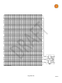
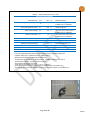
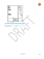
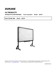
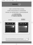
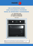
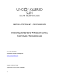
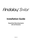
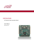
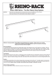
idealPV SSP1 – 220/270 Solar Panel Installation, Safety Instructions, Maintenance Photovoltaic modules user manual Please read carefully the following installation and safety instructions. Failure to comply may result in personal injury or property damage and may void the module warranty. Purpose of this guide This guide contains information regarding the installation and safe handling of idealPV photovoltaic modules. All instructions should be read and understood before attempting installation. If you have any questions, please contact us for further information. The installer should observe all safety precautions in this guide when installing modules. Before installing a solar photovoltaic system, the installer should become familiar with the mechanical and electrical requirements and local, regional, and national codes for photovoltaic systems. Keep this guide in a safe place for future reference. General Installing solar photovoltaic systems requires When connecting idealPV modules in series with specialized skill and knowledge. The installer a string consisting solely of other idealPV assumes all risk of injury, including risk of electric modules, only connect modules with the same shock. Module installation should be performed rated short circuit (ISC) rating. only by qualified persons. When connecting idealPV modules in series with All modules come with a permanently attached other modules of any other type, The ISC rating of 2 junction box and 4 mm wire terminated in Multi the idealPV module(s) must be less than or equal Contact PV connectors. to the highest ISC rating of any of the non-idealPV Each individual module can generate voltages module(s). Never install an idealPV SSP1 module greater than 35 volts (V) when exposed to direct in series with any module with an ISC of more sunlight. Contact with DC voltage of 35 V or more than 10A. is potentially hazardous. Exercise caution when If modules are connected in series, the total wiring or handling modules exposed to sunlight. voltage is equal to the sum of the individual When disconnecting wires connected to a module voltages. photovoltaic module that is exposed to sunlight, For arrays composed solely of idealPV modules, an electric arc may occur. Arcs can cause burns, multiple series-strings may be connected in fires, or other safety problems. Exercise caution parallel, but only if each series string can operate when disconnecting wires on modules exposed to at the same voltage.. idealPV modules have sunlight. nearly flat nominal power over a Voltage Photovoltaic solar modules convert light energy to Maximum Range (VMR) that begins at V = PMP / ISC direct-current electrical energy, and are designed (maximum power divided by short-circuit current for outdoor use. Proper design of support rating) and extends to VMP (panel’s rated structures is the responsibility of the system maximum-power voltage). For all strings to designer and installer. operate at the same voltage, they must have Modules may be ground-mounted, pole- mounted, overlapping VMR ranges. This is the “VMR overlap or mounted on rooftops. requirement.” To meet the VMR overlap requirement, the VMR of the longest string must Do not attempt to disassemble the module. Do not overlap the VMR of the shortest string. For remove any attached nameplates or components. example: For an idealPV SSP1 with a VMP of 30V, Doing so will void the warranty. a PMP of 200W and an ISC of 10A, the VMR is 20V Do not apply paint or adhesive to the module. (200W/10A) to 30V. This means that the panel power is close to its 200W rating from 20V to 30V. Do not use mirrors or other hardware to artificially A sting of 10 such idealPV modules would have a concentrate sunlight on the module. VMR of 200V to 300V and could be placed in When installing modules, observe all applicable parallel with strings of no fewer than 7 idealPV local, regional and national codes and regulations. modules (VMR of 140V to 210V), since the VMR for Obtain a building and/or electrical permit where the longer string overlaps the VMR of the shorter required. string. For arrays composed of a mix of idealPV modules Safety precautions for installing a and other types of modules, do not parallelsolar photovoltaic system connect strings unless each string has the same Solar modules produce electrical energy when voltage rating. exposed to sunlight. DC voltages may exceed 35 V on a single exposed module. Page 1 of 13 130327 If modules (or strings of series-connected Short-circuit current and open-circuit voltages should be multiplied by a factor of 1.25 when determining component voltage ratings, conductor capacity, fuse sizes, and size of controls connected to the module or system output. Refer to Section 690-8 of the National Electrical Code (NEC) for an additional multiplying factor of 125% (80% de-rating) which may be applicable. For systems composed entirely of idealPV modules, these design margins provide an extra margin of safety and efficiency for the balance of system (BOS) beyond the voltage, current and power limits contained with idealPV modules. For systems consisting of a mix of idealPV modules and other types of modules, the design margins above may be fully exercised in the normal operation of the array. modules) are connected in parallel, the total current is equal to the sum of the individual module (or string) currents. Keep children well away from the system while transporting and installing mechanical and electrical components. Completely cover all modules with an opaque material during installation to prevent electricity from being generated. Do not wear metallic rings, watchbands, ear, nose or lip rings or other metallic devices while installing or troubleshooting photovoltaic systems. Use appropriate safety equipment (Insulated tools, insulating gloves, etc.) approved for use on electrical installations. Observe the instructions and safety precautions for all other components used in the system, including wiring and cables, connectors, DCbreakers, mounting hardware, inverters, etc. Use only equipment, connectors, wiring and mounting hardware suitable for use in a photovoltaic system. Although idealPV modules may be intermixed with other types of modules, always use one type of idealPV and one type of non-idealPV module within a particular photovoltaic system. idealPV modules contain internal current limits and voltage limits. Under normal operating conditions and over the temperature and irradiance levels specified, idealPV modules will not exceed their rated VOC, VMP and ISC specifications. Under some conditions, nominal power may increase beyond rated PMP, however maximum output power is internally limited to VMP x ISC over the temperature and irradiance levels specified. Power output is zero at or above VOC. Do not impose output voltages on the output of an idealPV module that exceed 140V. idealPV modules consume negligible current if forced above their VOC but may be destroyed by externally imposed VOC voltages above 140V. In systems consisting of a mix of idealPV modules and other types of modules, please be aware that under normal operating conditions, other types of PV modules will produce more currents and voltages outside the ranges listed in their data sheets. Data-sheet values are applicable at standard test conditions, with temperature-related variations listed separately, so actual voltage and current ranges must be calculated by extrapolation. Care must be taken not to exceed the 10A maximum reverse current and 140V maximum output voltages of any idealPV module. General Installation notes Drainage holes must not be covered with any part of the mounting system. The junction box has a breather port which must be mounted facing downward and must not be exposed to rain. The junction box should be on the lowest edge of the mounted module so the breather port is oriented correctly. Do not lift the module by grasping the module’s junction box or electrical leads. Do not stand, sit or lie on the module. Do not drop the module or allow objects to fall on the module. Do not place any heavy object on the module. Inappropriate transport and installation may damage the module glass or frame. Mechanical Installation Selecting the location Select a suitable location for installation of the module. For optimum performance, the module must be facing true south in northern latitudes and true north in southern latitudes. For arrays composed entirely of idealPV modules, multiple module headings and angles within the same string are permitted. Array power will be the maximum available with the incident insolation available to each module independent of the illumination of any other module. For detailed information on optimum module orientation, refer to standard solar photovoltaic installation guide or a reputable solar installer or system integrator. Page 2 of 13 130327 The power from the lower 20% of an idealPV module is independently optimized and added to the power from the upper 80% of the module. In installations where shade is unavoidable, such as row to row shading or roof vent pipes, power loss due to shading will be minimized when the idealPV module is oriented in portrait configuration such that any shadows fall primarily on the lower 20% of the module. Periodic partial shading does not cause cell heating or damage to an idealPV module. Observe all instructions and safety precautions included with the mounting system to be used with the module. Do not install the module near equipment or in location where flammable gases can be generated or collected. Select a proper mounting structure with material thickness of 4 mm (minimum). All mounting hardware must be temperature rated at 90°C (minimum). Do not drill holes in the glass surface of the module. Doing so will void the warranty and could create an electrical hazard. Do not drill additional holes in the module frame. Doing so will void the warranty. Modules must be securely attached to the mounting surface using four mounting holes for normal installation. If heavy wind or snow loads are anticipated, additional mounting points should also be used. Please see the drawing below. The design load for individual module is 30 lb/ft2. Site Load calculations are the responsibility of the system designer or installer. The module must be attached to a support rail using M6 type stainless steel bolt, double washer and nut. Torque 8 N-m. The recommended standoff height is 6 in. The mounting structure and hardware must be made of durable, corrosion, and UV-resistant material. Electrical Installation Grounding All module frames must be properly grounded. Grounding is achieved through secure attachment to the array frame. The array frame shall be grounded in accordance with NEC Article 250. Also observe all local, regional, and national electric codes and regulations. A bonding or toothed washer is required to make proper and reliable electrical grounding connection with the anodized aluminum frame. Devices listed and identified for grounding metallic frames of PV modules are permitted to ground the exposed metallic frames on the module to a grounded mounting structure. Per NEC 250.136, electrical equipment secured to and in electrical contact with a metal rack or structure provided for its support and grounded by one of the means indicated in NEC 250.134 shall be considered effectively grounded. Consider using a GBL4 Solar Module Grounding Lug, rated for outdoor use. The module grounding conductor is to be larger than # 10 AWG. When using a GBL4 Solar Module Grounding Lug, the grounding conductor should be inserted into the opening indicated in the figure, and secured using the set screw. General electrical installation Do not use modules of different configurations in the same system. This module is supplied with Multi Contact connectors for electrical connections. Refer to Section 690.31 of the NEC to determine appropriate types and temperature ratings of conductors. When working with any wiring attached, connected to, or potentially connected to any solar module, all of the solar modules in the circuit should be completely covered with an opaque material to prevent electricity from being generated while connecting or disconnecting conductors. idealPV modules are capable of generating up to their rated ISC and/or VOC in very low light. Always consider the output of any idealPV exposed to any light as an energized high-voltage circuit. Refer to Section 690.8 and 310 of the NEC to determine over-current, conductor capacity, and size requirements. "Rated electrical characteristics are within 10 percent of measured values at Standard Test Conditions of: 1,000 W/m2, 25°C cell temperature and AM 1.5. WARNING Electrical shock hazard! Do not touch bare conductors or other potentially energized parts. Maintenance idealPV recommends the following maintenance items to insure optimum performance of the module: Clean the glass surface of the module as necessary. Use water and a soft sponge or cloth for cleaning. A mild, non-abrasive cleaning agent can be used if necessary. Do not use dishwasher detergent. Electrical and mechanical connections should be checked periodically by qualified personnel to verify that they are clean, secure, and undamaged. Problems should only be investigated by qualified personnel. Follow the manufacturers’ maintenance and inspection schedules for all other components used in the system. Page 3 of 13 130327 Shutting down the system Completely cover all modules with an opaque material to prevent electricity from being generated while disconnecting conductors. Disconnect system from all other power sources in accordance with instructions for all other components used in the system. The system should now be out of operation and can be dismantled. In doing so, observe the all safety instructions as applicable to installation. Electrical ratings The electrical characteristics are within +0 / -2.5% of the indicated value of ISC, VOC, VMP over the temperature and irradiance levels specified. IMP and PMP are minimums under Standard Conditions (irradiance of 1,000 W/m2, AM 1.5 spectrum and a cell temperature of 25°C/77°F). Both IMP and PMP have -0.39%/°C nominal temperature coefficients Disclaimer of liability Because the use of this manual and the conditions or methods of installation, operation, use and maintenance of photovoltaic products are beyond our control, we do not accept responsibility and expressly disclaim liability for loss, damage or expense arising out of or in any way connected with such installation, operation, use or maintenance. The information in this manual is based on our knowledge and experience and is believed to be reliable, but such information including product specification (without limitations) and suggestions does not constitute a warranty, expressed or implied. idealPV reserves the right to change the manual, the product, the specifications, or product information sheets without prior notice. Information about manufacturer: idealPV 19640 Auburn Drive Cupertino, CA 95014 www. idealPV.com k@ idealPV.com Please consult your dealer or the manufacturer concerning the warranty of your modules. If you have any further questions we’ll gladly assist you. Note: This manual can be subject to technical modifications without notice Page 4 of 13 130327 Differences between idealPV modules and other types of solar modules idealPV modules may be designed and installed using the exact same rules and methods as used on other types of PV modules. Use of industry standard design margins suitable for similar modules will generally result in a system with superior performance and wider safety margins than systems utilizing other types of modules. At the option of the designer and installer, power generations systems may be built for idealPV modules that have still higher performance and flexibility. Considerations Maximum open circuit voltage VOC Maximum short circuit current Isc Voltage for maximum power VMP Current for maximum power IMP Maximum power point PMP Maximum system voltage and modules per string Minimum modules per string Matching of modules per string in parallel Wiring plant oversize for transient high irradiance events Short between string cables Wiring Plant I2R Losses Other types of solar models idealPV solar modules Specified at STC, 1,000 W/m2, AM 1.5 spectrum. VOC increases with illumination levels and decreasing temperature. It is common to allow for a VOC tolerance of 30% over STC depending on the coldest recorded site temperature and atmospheric conditions such as cloud lensing. 2 Specified at STC, 1,000 W/m , AM 1.5 spectrum. Isc increases with illumination levels and with increasing temperature. It is common to allow for an Isc tolerance of 25% over STC depending on the warmest temperature and atmospheric conditions such as cloud lensing. Specified at STC, 1,000 W/m2, AM 1.5 spectrum. VMP increases with illumination levels and with decreasing temperature. It is common to allow for a VMP tolerance of ±30% over STC depending on the coldest and warmest recoded site temperature & atmospheric conditions such as cloud lensing. Specified at STC, 1,000 W/m2, AM 1.5 spectrum. IMP increases with illumination levels and with increasing temperature. It is common to allow for an IMP tolerance of +25% over STC depending on the coldest and warmest recoded site temperature and atmospheric conditions such as cloud lensing. IMP at non STC conditions may exceed specified ISC at STC conditions. Specified at STC, 1,000 W/m2, AM 1.5 spectrum. Maximum power exists at a single voltage and current point. Since IMP is directly dependent on irradiance, A string may only achieve the maximum power available to each solar module if all solar modules have the same irradiance and the same IMP. This requires each solar module in a string to be mounted on the same heading and angle and to have IMP closely matched. Specified as an absolute maximum from -20°C to +55°C ambient, and 2 irradiance up to 1,500 W/m . No additional tolerance needs to be considered. Maximum panels per string is typically the maximum system voltage / (VOC + 30%), VOC margin required to account for coldest day recorded at site. Must be large enough to maintain VMP above inverter VMP range on warmest day recorded at site. May need to be traded off for maximum system voltage limitation. Must match. Must oversize ampacity above specified ISC to allow for transient atmospheric events such as cloud lensing due to the direct, unlimited relationship between irradiance and ISC, IMP. May cause a sustained plasma Arc that may not be extinguished by AFCI or dc disconnect. Losses increase with increasing temperature: falling PMP, falling VMP, increasing IMP and increasing copper resistance causing increase in I2R loss. BOS efficiency falls with temperature. In a typical 2Ω string, system BOS loss increases from 4.0% to 4.8% as ambient temperature goes from 20°C to 40°C Specified as an absolute maximum from -20°C to +55°C ambient, and irradiance up to 1,500 W/m2. No additional tolerance needs to be considered. Specified as an absolute maximum from -20°C to +55°C ambient, and 2 irradiance up to 1,500 W/m . No additional tolerance needs to be considered. Specified at STC, 1,000 W/m2, AM 1.5 spectrum. IMP increases with illumination levels and with decreasing temperature. IMP is limited to ISC from -20°C to +55°C ambient and irradiance up to 1,500 2 W/m . Specified at STC, 1,000 W/m2, AM 1.5 spectrum. At STC, maximum power exists over a range of voltages from PMP/ISC to VMP (at IMP). As irradiance falls, PMP and IMP (at VMP) fall. However, ISC does not fall. Therefore the effect of reduced irradiance is reduced voltage while current increases up to ISC. A string may achieve the maximum power available to each solar module when each solar module has a different irradiance. Maximum panels/string = Maximum system voltage / VOC. Maximum VOC not dependent on temperature. Minimum VMP not dependent on temperature. Need not match with overlapping VMR Maximum ISC and IMP limited to specified maximum and not dependent on irradiance. Will not sustain a plasma Arc does not depend on AFCI or dc disconnect. Higher, nearly flat BOS efficiency with increasing temperature: falling PMP, constant VMP, falling IMP and increasing copper resistance 2 compensate I R loss. Typical 2Ω BOS loss is 2.2% flat over temperature. Page 5 of 13 130327 IV Differences Other types of modules may have a voltage and current profile as shown below. As shown above, the module begins to conduct current at about -1.8V where all three of its bypass diodes conduct in series. With a string fuse of 15A, the jbox of the module shown above would be dissipating 75W at the fuse rating and would tend to get quite hot. It is normal for a module to conduct this way when a large shadow is cast upon the panel with the rest of the string fully illuminated. Simply standing in front of a module will cause it to operate this way. If any of the bypass diodes or their interconnect have failed, the module may be quickly destroyed by shading it in this way because full string voltage may be applied to a single cell. When a module of the type shown above is forced above its VOC it will immediately begin to conduct current. This mode of operation commonly results when the Electro Magnetic Pulse from a nearby lightning strike causes a large current to be induced in the wiring of a string of solar panels. The mode can also result when a string with fewer modules is wired in parallel with one or more strings with more modules. For the graph above, a string of 8 modules placed in parallel with strings of 10 or more modules could result in overcurrent in the smaller string. Short strings can result from “patching across” or “bridging” a bad module in a string by disconnecting the failed module and connecting the modules to the left and right of it. For the type of module shown above, bridging is generally considered poor practice. A typical voltage and current profile for the idealPV SSP1 module is shown below. An SSP1 begins to conduct when forced below -0.3V where at least one of its four reverse protection diodes begin to conduct in parallel. With a string fuse of 15A, the jbox of an SSP1 will be dissipating 25W and will show little additional warmth. Single reverse protection diode failures have little effect on SSP1 modules. When an SSP1 is forced above VOC and below 140V its current goes to near zero. When the voltage is forced above about 140V, the SSP1 is designed to gradually conduct reaching the recommended string fuse rating at about 150V. Lightning induced EMP will raise the string voltage without creating large current stresses on the modules, connectors, wiring or fuses. Standard surge suppressors, spark gaps, or even the inverter’s dc link capacitors may safely dissipate most short transient rises of string voltage. The SSP1 IV response also allows deliberate design of arrays with different numbers of modules in each string. For the SSP1 shown above, A string of 11 SSP1s could be permanently connected in parallel with strings of up to 15 SSP1s. Near full power would be produced by both the short and long strings. For temporary repairs, strings as short as 5 SSP1 modules may be safely connected to a 600V system. Note that operating an SSP1 module above its VOC will not contribute any PV power to the array. Page 6 of 13 130327 Power Point and Range Differences Other types of modules may have a power profile as shown below. The major feature of this profile is the existence of a single, maximum power point. The point will shift right and left with temperature. Inverter ripple and other disturbances in panel voltage may reduce power. Peak power for differently lit modules will not occur at the same current for modules in series. Peak power for differently lit modules will not occur at the same voltage for modules in parallel when the modules are at different temperatures. Note that operating temperature is a function of illumination. idealPV SSP1 modules typically have the power profile shown below. As can be seen by the flat tops, near maximum power exists over a range of voltages. A Maximum Power Range. The high voltage end of the range does not shift with temperature or illumination. The low voltage end of the range shifts lower for lower levels of illumination and/or increasing temperature. Inverter ripple and other disturbances in panel voltage have little effect on power. Peak power for differently lit modules occurs at a current common to each and different voltage when the modules are connected in series. Peak power for differently lit modules occurs at a voltage common to each and different current when the modules are connected in parallel. Important note: for IV and Power Point Differences It is generally safe to replace other types of modules with idealPV SSP1 modules after verifying that the specifications of the module you are replacing are compatible with the SSP1 you are using. It is generally NOT SAFE to replace idealPV SSP1 modules with other types of modules. idealPV modules may be used in arrays designed for other types of modules and even intermixed with other types of modules of similar ISC, IMP, VMP and VOC ratings. Such designs are generally much more restricted allowing idealPV SSP1 modules to adapt to the operating points of the other types of modules. DO NOT utilize other types of modules in arrays designed for idealPV SSP1 modules. Other types of modules may not be safely operated over the wider ranges allowed for SSP1 modules. Page 7 of 13 130327 Mounting : Mounting - The following mounting hardware is in combination with the following series. The applied torque is 8 Nm. Model/Series Mounting hardware configuration Hardware All Bolt Washer Nut Washer Material Stainless steel Size M6 Number provided 1 (PER HOLE) Page 8 of 13 130327 Panel photograph Page 9 of 13 130327 Panel schematic Page 10 of 13 130327 idealPV SSP1_224W-30VMP-40VOC-10ISC Electrical Parameters Nominal Power PMAX 224 W Minimum @ STC Voltage at maximum power VMP 30 V +0/-2.5% over TA -20 to +55°C irradiance up to 1,500W/m² Current at maximum power IMP 7.46 A Minimum @ STC Open Circuit Voltage VOC 40 V +0/-2.5% over TA -20 to +55°C irradiance up to 1,500W/m² Short circuit current ISC 10 A +0/-2.5% over TA -20 to +55°C irradiance up to 1,500W/m² Maximum system voltage 600 V Maximum series fuse rating 15 A Maximum imposed voltage +140 V Externally imposed + to - Maximum imposed current -10 A Externally imposed – to + Solar cells per module 230 Cells (10x23 Matrix) Solar cell size 156x39 mm Use only recognized mating connector with 14AWG minimum insulated copper wire. Insulation rating 90°C, Application Class A. Safety Class II. Measurement Tolerance on electrical parameters ±5%. All parameters are at STC 25°C cell temperature, 1,000W/m² irradiance and AM 1.5. Specifications subject to change without prior notice. All mechanical dimensions are ±2mm. Power falls 3% maximum from VMP to V = PMAX / ISC @STC This solar module produces no current when its output voltage is forced above V OC This solar module consumes negligible current when its output voltage is forced above VOC Marking Label Page 11 of 13 130327 Page 12 of 13 130327 Dimensions and Weights Cells / Module Module Dimensions Module Thickness (Depth) Approximate Weight 60 Cell (equivalent Si) 1653mm x 982mm 46mm 18.7kg Page 13 of 13 130327