
1
SR 2010
Combine Harvester
Instruction book
Sampo Rosenlew Ltd
P.O.Box 50
FI–28101 PORI, FINLAND
11/2012
0814421
This book
The purpose of this book is to enable the Owner/Operator to handle and maintain the combine
efficiently. Time spent in becoming familiar with the instruction book now will save time in
the field.
Wide variations in operating conditions make it impossible for the Company to make
comprehensive or definite statements in its publications concerning performance and the use of
its machines, or to accept liability for any loss or damage which may result from errors or
omissions.
The specifications and illustrations contained in this book pertain to combines manufactured
for certain countries. Due to differing laws and requirements in various countries, some
apparent discrepancies may result between any particular and those depicted in this book.
Some accessories and optional equipment appearing in this book are not necessarily available
in all territories.
We reserve ourselves the right without notice to change construction, settings, equipment or
instructions of the combine.
The manufacturer is not responsible for any modifications that have been done to the machine
after it has left the factory.
SAMPO-ROSENLEW Ltd
-3-
Content
This book 3
SAMPO ROSENLEW Service 5
Warranty, pre-delivery and installation 6
Safety Precautions7
Type Marking 12
EC Declaration of Conformity 13
Technical specification14
Opening the guards 15
Cutaway picture of the combine 17
Operators controlsand instruments
18
Signs and Symbols 19
Operation and adjustment 20
Threshing equipment 25
Driving and threshing instructions 38
Average settings for threshing 44
Service and maintenance 45
Electrical system 63
Hydraulic81
Lubrication83
Summary of periodical procedures
85
Storing for winter 86
Recommended tools and accessories 88
Conversion for corn harvesting 89
Discarding of the combine 92
-4-
SAMPO ROSENLEW Service
Owners are strongly advised to make use of the widespread network of Sampo Rosenlew
Importer and Dealers in connection with any service problems and adjustments which may
arise.
Sampo Rosenlew Importer and Dealers are specially trained and equipped for the purpose of
advising users on any special problems arising as a result of local conditions.
They are also able to call on Technical Staff of Sampo Rosenlew factory for advice.
When replacement parts are required, insist on genuine Sampo Rosenlew Service Parts. All
Distributors and Dealers have agreed not to sell parts other than those which are manufactured
or recommended by the Sampo Rosenlew and, as extensive damage is liable to results
from the use of inferior quality parts, users are advised to buy Service Parts only from an
authorised Sampo Rosenlew Importer / Dealer.
In the event of your requiring the name and adress of the Importer in any particular area,
apply to
Sampo Rosenlew Ltd
P.O.Box 50
FI – 28101 PORI, FINLAND.
-5-
Warranty, pre-delivery and installation
The Company, when selling new goods to its Distributors, gives a warranty which, subject
to certain conditions, guarantees that the goods are free from defects in material and
workmanship.
The Company’s Distributors and Dealers are required to give the benefit of a similar
warranty to the first retail purchaser of all new goods supplied by the Company, and users
should enquire of the Distributor or Dealer from whom they purchase as to the terms of the
warranty made available to them.
Before delivering a new combine to the Customer’s premises, it is the responsibility of the
Distributor to conduct a pre-delivery check on the machine. This consists of a series of detailed
inspections, adjustments and functional checks, which should ensure that when received by
the Customer the combine is ready to start work immediately. Upon delivery the Distributor
is required to instruct the Customer in the basic principles and operating procdure of the
combine. This is termed Combine Installation, which should include instruction on controls
and instruments, field settings, maintenance requirements, safety precautions and winter
storage, and should preferably be undertaken in the presence of all who will be concerned
with the operation and maintenance of the machine.
IMPORTANT
Always quote the machine serial number in any communications to your distributor/dealer.
Combine Serial Number:
_____________________
Cutting Table Serial Number:
_____________________
Engine Serial Number:
_____________________
Model Details:_____________________
Owner/Operator: _____________________
Installation Date:
_____________________
Keep this book safely for convenient reference
This book is published for world wide distribution, and the availability of equipment shown
either as basic or accessory varies according to the territory in which the combine is to be
used. Details of equipment available in your area can be obtained from your Sampo Rosenlew
Distributor / Dealer.
-6-
SAFETY PRECAUTIONS
Read carefully these instructions on safety and use before starting to operate the combine. Time
spent in becoming familiar with the instructions now, will save you money or may even spare
you from injury.
Before accepting the delivery of the combine, make sure it conforms to the delivery contract.
Do not fit the combine with any accessories not approved of by the Manufacturer. The Manufacturer of the Combine is not responsible for any damage or injury caused by such accessories
either to people or property.
1. TRANSPORTATION ON A VEHICLE OR BY RAIL
Make sure you know the measurements and weights of the combine and the transporter. When
driving the combine on the road, comply with the relevant statutory traffic regulations. Use increased tyre pressure (2-2.5 Bar) to improve stability.
Fix the combine securely in the transporter. For road transport, lower the cutting table fully or
remove it.
2. DRIVING IN TRAFFIC
When driving on public roads, comply with the
relevant statutory traffic regulations. Remember that the combine has rear-wheel steering.
Brake pedals must be latched together. Test
brake functions before driving on the road.
Brake smoothly as the rear wheels of the
combine easily rise from the ground when
applying the brakes violently. The threshing
equipment must be disengaged, the straw dividers removed and the unloading pipe locked
for road transport.
The knife guard and the front warning signs
shall be fitted onto the table. (Fitting of the
front warning signs in accordance with the enclosed illustrations.)
The front and rear lights and the rear-view
mirrors shall be correctly aligned.
Never drive downhill with the gear in neutral.
Never carry passengers on the machine.
Never use the combine for transporting goods.
Always have the grain tank empty when driving on the road.
3. THRESHING
Get familiar with the structure of the combine
by studying the manual before starting threshing. Wear appropriate clothing. Avoid loose
clothing that may get entangled in moving
parts. Use of hearing protectors is recommended. Make sure the protective guards
are properly attached and in good condition.
Sound the signal to warn people around the
combine before starting the engine. Adjust
the rear-view mirrors before starting to ensure
good visibility of the road or the working area
behind.
-7-
Never use the combine for anything but threshing.
Manual feeding of crops onto the cutting table is prohibited.
Before starting, particularly reversing, make sure that
everybody nearby is aware of your intentions.
Test the brakes as soon as you start, and stop immediately if the brakes or steering operate defectively.
Never adjust the seat or steering wheel while driving.
Never leave the cab while the combine is moving.
Never leave the engine running unattended.
Do not open any guards with the engine running.
Do not open the safety grate on the grain tank cover
with the engine running.
Do not climb on top of the grain tank or the straw
walkers with the engine running, and do not let anybody else do it either.
Beware of the cutting mechanism and the rotating
chopper knife.
Keep in mind that with the chopper rotating, there is a
20 m no-access danger zone behind the chopper.
Drive carefully on hillsides; the combine may overturn, particularly with the grain tank full.
The combine cab is no safety cab.
THE RIGHT-HAND SIDE DOOR OR WINDOW
MAY BE USED AS AN EMERGENCY EXIT. TO
OPEN THE SIDE WINDOW FIRST REMOVE THE
WINDOW GASKET BY PULLING FROM THE
LOOP MARKED WITH ”EXIT”.
Note the recommended safety distances when
threshing under power lines.
Stop the engine before cleaning or servicing the
combine.
Stop the combine and the engine immediately if
there is an alarm or any abnormal sounds or smells.
Find out the reason for them, and solve the problem
before carrying on with threshing.
Support or lock the cutting table and the reel before
going beneath them.
Never clean the combine without proper equipment.
When leaving the combine, lower the cutting table,
lock the parking brake, stop the engine and remove
the ignition key.
SAFETY DISTANCES WHEN THRESHING UNDER
OPEN-WIRE POWER LINES
The minimum clearance between the combine and
power lines with voltage must be in accordance with
the enclosed illustration, in which the danger zone is
darkened.
Low-voltage power lines, fig. B3 (240/400V) can be
distinguished from high-voltage line, fig. B4...B5 (over
1 kV) by the smaller insulators and the fact that there
are usually 4 low-voltage lines.
In case the height or voltage of the power line is
difficult to estimate, the Electric Company shall be
consulted.
-8-
In Case of an Accident
If there is an accident despite all precautions,
keep calm and consider carefully what to do.
First try to reverse the combine away from the
power line. If there are other people near, ask
them to check that the combine is not stuck in
the line.
If the combine is just leaning against the lines,
try to drive it away from them. Follow the advice from the people nearby. Due to their own
safety, they shall stay a minimum of 20 metres
away from the combine touching the power
line.
If the combine cannot be driven off, and you
have to leave the combine, jump down with
your feet together in order not to touch the
A5
combine and the ground simultaneously. Do
not make yourself a conductor through which
electricity can pass; the real danger lies in
touching the combine and the ground simultaneously. Get away from the combine jumping either with your feet together, or with only one foot on the ground at a time.
Otherwise the electric field on the ground may create a fatal electric current between your legs.
You will be safe at a distance of 20 metres from the combine.
Beware of broken power lines lying on the ground.
A combine touching a power line may catch fire. Leave the combine immediately if smoke starts
coming from the tyres.
Make sure the combine will be guarded at a safe distance. Do not try to get on the combine
even if the power in the power lines may seem to have gone off.
Remember that open-wire lines never have a ”blown fuse”, but they are always dangerous unless made dead by an electrician. Even if the power went off, it might come back on in a while
due to technical reasons. This may be repeated several times.
Contact the Electric Company and inform them about the exact site of the accident. By doing
this, any risk can be eliminated and the fault repaired.
Ask the Electric Company for advice and follow it. Inform them about any contact with power
lines even if there was no actual damage.
Source: Koneviesti Magazine 15/87
4. REPAIR AND SERVICE
Always keep the combine in good condition.
Check the condition of fast moving parts daily. Pay special attention to the transmission
mechanism and the rotating chopper knives.
Replace defective parts before they become
dangerous. Clean, repair and service the
combine with the transmission and engine off,
the ignition key off the ignition switch and the
master switch in its on position.
Disconnect the negative battery cable before
repairing the engine or any electrical instruments. Do not use inappropriate tools to connect and disconnect the battery.
Do not make an open fire or smoke near the
battery. Handle the battery acids with care.
Do not add air in the tyres without a pressure
gauge due to risk of explosion.
Do not add coolant with the engine running.
-9-
Do not remove the radiator cap from an overheated engine.
Do not refuel with the engine running.
Do not smoke while fuelling.
Do not adjust the hydraulic working pressure without a pressure gauge due to possible damage
to the hoses.
When servicing the hydraulics, be aware of the high pressure in the system. Make sure there is
no pressure in the system or in the pressure accumulator before disconnecting the connectors.
Never use over-sized fuses; they involve risk of accident.
Never start the combine with anything but the ignition key.
When refitting a wheel, tighten the fixing screws to the correct torque.
Attach accessories such as the trailer using the appropriate equipment.
Tow the combine only from designated points.
5. THE LAWS AND REGULATIONS
Combine harvester is a complex device, and dangerous if misused. User manual must always
be preserved with the machine at the place reserved for it and if needed, new drivers should
be instructed to operate the machine Different countries have different safety at work and traffic
regulations. Get to know the existing regulations of your area.
This symbol in the manual refers to a special risk involved in taking a certain measure,
due to which extra caution shall be practised.
6. FIRE SAFETY
Two factors are needed to start a fire: flammable material and ignition; oxygen is always available.
Threshing generates a lot of light and highly flammable dust. Therefore it is important to clean
the combine on a regular basis, and the engine compartment daily.
Oil and fuel leaks increase the risk of fire. Repair any defects immediately.
High temperature near the exhaust pipe makes the area fire-prone. A fire may also be caused by
a short circuit in the electric system, slipping of an overloaded belt, a damaged bearing or overheating of the brakes.
Make sure there is at least one 6-kilo class AB fire extinguisher located in its marked place on
the combine at all times.
In particularly dry and dusty circumstances another similar extinguisher is to be placed near the
engine compartment.
- 10 -
Hazard pictorials
Danger
How to avoid it
Nr.
Subject to danger due to
insufficient information
Read the manual before starting the combine
1
A raised part may fall down
Support raised parts before going under
them
2
Stop the engine and remove the ignition
key before removing any guards
3
Gap in belt drive
Getting entangled in moving parts
Stop the engine and remove the ignition
key before removing any guards and/or
reaching into a danger zone
Getting entangled in rotating auge
Stop the engine and remove the ignition
key before removing any guards
5
Getting entangled in rotating auger
Do not reach into an opening with the engine running
6
4
Falling into moving machin- Stop the engine and remove the ignition
ery
key before removing any guards
7
Danger caused by flying
objects
Keep at a safe distance from the combine
8
Kickback or upward motion
of arm handle
Stop the engine and remove the ignition
key before inserting the handle
- 11 -
9
Symbol
Type Marking
When ordering parts or service, quote the type marking and serial number shown on the
machine plate of the combine. There is a separate machine plate in cutting table. Quote also
table serial number and type marking when ordering parts for cutting table.
When ordering engine parts, also quote the engine number.
Machine plate of the cutting table
Machine plate of the combine
Engine serial number
Note! Left side of the combine = The side of cabin ladders
Right side of the combine = The side of fuel tank
- 12 -
- 13 -
Technical specification
ISO 6689 standard has been used in measuring.
Length with header 6.40 m
without header 4,10 m
Width 2.50 m
Height, - with cab 3.30 m
- without cab 3.30 m
Ground Clearance 0.36 m
Weight*) - with cabin and 2.0 m table 3 450 kg
Front Tyres - wheel track 1.40/1.57 m
- size / air pressure 12.4R24 1,1 Bar
360/70R24 1,1 Bar
Rear Tyres - wheel track 1.27 m
- size / air pressure 11.5-15.3 1,0 Bar
Wheel Base 1.90 m
Turning Radius 3.50 m
Driving Speed I 0...5 km/h
II 0...7.5 km/h
III 0...20 km/h
Engine: VM Motori
D754TE3 60kW @2600RPM
Working Width 1.6 / 2.1 / 2.4 m
Cutting Width 1.5 / 2.0 / 2.3 m
Cutting Height -7...+70 cm
Knife, Number of Strokes 460 cycles/min
Cylinder - width 0.78 m
- diameter 0.50 m
- number of rasp bars 7
- number of revolutions 400...1150 r/min
- “ optionally 300...700 r/min
Concave - angle of wrap 108 °
- length 49 cm
- area 0.38 m2
- number of rasp bars 12
Separating Areas
- straw walkers 1.40 m2
- chaffer 0.70 m2
Return circuit optionally
- sieve 0.47 m2
Grain Tank - volume 800 / 1700 litres
- unloading height 2.80 / 3.10 m
Fuel Tank Volume 140 l
Cooling System Volume 14 l
Engine Oil 6,8 l
Gear Box Oil 3,5 l
Hydraulic Oil 25 l
Noise level in cabin 82 dB(A) (O.E.C.D-1967/6)
“ without cab 88 dB(A) “
The weighted acceleration subjected to operator’s arms does not exceed 2,5 m/s2.
(ISO-5349)
The weighted acceleration subjected to operator’s body does not exceed 0,5 m/s2.
(ISO-2361)
*) Combine in threshing condition, fuel tank filled, with driver (75 kg).
- 14 -
Opening the guards
To ensure safety, the movable guards of the
combine have been equipped with a locking
device. They cannot be opened without
an appropriate tool. The tool is delivered
with every combine. It hangs on a hook on
the cabin back wall. The guards are locked
automatically when closing. In some guards
also an additional fixing device is used.
- Unlock the guard on the left side of the
cutting table by placing the tool in the hole
and turning in direction of the arrow.
- Unlock the reel belt drive guard by pushing
the latch open with the tool. Before that
the rubber fittings have to be opened. The
guard can be supported in an open position
by means of a support rod. The rod end is
placed in the hole of the lower stop bar.
- Unlock the side guards of the combine
by placing the tool in the hole turning in
direction of the arrow. The guard is opened
by pulling the lower edge outwards. The
guard
will be locked to open position automatically.
When closing the guard release the stop by
lifting the guard slightly and pushing up the
stop piece located around the gas spring.
- 15 -
STRUCTURE AND FUNCTION OF THE PLOT COMBINE
This combine have been made for harvesting the seeds of different type of crops specially in
experimental plots or smaller fields. The combine can be equipped with several special
equipment for to meet customers needs.
The cutting and feeding equipment take the crop in for threshing
The straw dividers limit the crop to be cut and bring it within the reach of the reel.
The reel, together with the crop lifters lift up the laid crop and take it from the cutting knife to
the table auger. The table auger gathers the cut crop and feeds it to the crop elevator, which
takes the crop forwards to be threshed.
The reel is equipped with brush which cleans the front of the table after harvested plot. The
air blast from the cleaning fan blows the bottom of the table and upper part of feed conveyor
clean.
The threshing mechanism separates the grains from the straw
The threshing cylinder beats the grain off on the concave. The grain, most chaff and bits of
straw go through the concave. The rear beater and the concave extension take the threshed
straw material to the straw walkers.
The separating and cleaning equipment screens the grains
The straw walkers separate the grains from the straw and eject the straw out to the field from
the rear of the combine. The grains run along the bottom grooves to the grain pan. The grain
pan takes the threshed material to the shaker shoe.
The chaff and light stuff are sorted topmost and the grain at the lowest during the
transportation.
The grain falls through the sieves at the first end of the shaker shoe to the grain conveyor and
are transported from there to the top of grain tank. The grains harvested in each plot can be
weighed in weighing hopper or it can go direct to the grain tank.
The air stream from the fan transports the lighter trash over the shaker shoe end out of the
machine.
After the straw walkers, the straw is either discharged uncut into the field or taken to the
chopper, which cuts and spreads it out.
Special options.
The combine can be equipped with weighing unit with which it is possible to measure the yield
of each plots or bagging unit which allows to take grains into bags or direct to the tank.
The combine can be equipped with a special corn header and other parts needed for corn
harvesting.
For to harvest very brittle crops there is available lower cylinder speed range 300...700 RPM.
- 16 -
Cutaway picture of the combine
1.
2.
3.
4.
5.
6.
7.
Straw Dividers
Reel
Cutter Bar
Table Auger
Crop Elevator
Threshing Cylinder
Rear Beater
8.
9.
10.
11.
12.
13.
14.
Engine
Gear Box
Concave
Grain Pan
Fan
Grain Conveyor
Shaker Shoe
- 17 -
15.
16.
17.
18.
19.
20.
Sieve
Chopper
Weighing
Grain tank
Straw walkers
Straw Alarm
Operators controls
and instruments
Operator’s Platform (Fig. 2)
A
Table Height Indicator
B
Flasher Indicator Switch
C
Steering Wheel
D
Brake Pedals
E
Parking Brake Lever
F
Table Clutch Control
G
Instrument Panel
H
Gear Lever
J
Traction Speed Control
K
Grain Tank Unloading
L
Concave Adjustment Wheel
M
Threshing Clutch Control
N
Seat
Instrument Panel (Fig. 3)
A
Cylinder and Fan Speed Indicator
B
Control Lights
C
Table Pressure Indicator
D
Warning Lights
E
Warning Light
F
Air Filter Blockage Indicator
G
Speedometer and Hour Meter
H
Thermometer
I
Fuel Gauge
K
Throttle Lever
L
Fuse Boxes
M
Ignition Switch, Starter and Electric Stop
N
Concave Clearance Indicator
O
Ashtray
P
Electric Outlet
Switches (Fig. 4)
A
Rotating Flasher (optional)
B
Emergency Flasher
C
4WD Switch (optional)
D
Cylinder Speed
E
Fan Speed
F
Front Working Lights
G
Rear Working Lights
I
Head Lights
J
Cutting Table Height
K
Reel Height
L
Change of Speed Indicator Display cyl./ fan
M
Reel Speed Control
N
Reel Fore and Aft Control
R
Horn / Reset of Tank Full Alarm
S
Vertical Knife Left (optional)
T
Vertical Knife Right (optional)
U
Reversing of Cutting Table
3
4
- 18 -
Signs and Symbols
Ignition Lock / Starting
Speed Control Lever
Stop Control
Engage of Cutting Table
Oil Pressure Warning Light
Grain Tank Unloading
Alternator Warning Light
Cylinder Speed
Throttle Control
Concave Clearance
Gear Change Decal
Horn Button
Flashers
Anti-dazzle Switch
Headlights
Working Lights
Reel Fore & Aft Control
Reel Speed Control
Cleaning Fan Speed Control
Cleaning Air Direction
Reversing of Cutting Table
Rotating Flasher
Windscreen Wipers
Emergency Flasher
Cabin Heating Control
Return Alarm
Air Conditioning Control
Straw Alarm
Parking Brake
Coolant Temperature Alarm
Table Height Control
Four-Wheel Drive
Reel Height Control
Engage of Threshing unit
Full Grain Tank
Grain Elevator Alarm
- 19 -
Operation and
adjustment
Steering Wheel (Fig. 5)
To release the steering column locking,
depress pedal A and move the steering
wheel to the required position.
Seat (Fig. 6b)
1. To adjust the fore and aft position,
releaselever A and move the seat to
the required position.
2. Adjust the height with hand wheel B.
3. Tilt the back rest with hand lever C
4. Tilt the arm rest with roller D.
5. Adjust the height of the seat top position with hand wheel E.
6b
- 20 -
Brakes (Fig. 7)
While Driving and Turning
The mechanical outer shoe brakes operate
on the front wheels through the drive shafts.
They may be used separately as steering
brakes by releasing locking pin A. When driving on the road, the brake pedals must be
latched together.
7
Brake (Fig. 7a) (models
with no hand brake)
By latching the brake pedals together and
locking them in their bottom position using
lever B, the parking brake is on. The parking
brake is only used when parking the
combine, and it must be released when
moving.
Hand brake (Fig. 8) (models
equipped with it)
The hand brake affects the intermediate
shaft in the gear box. Use the brake only
when parking, and fully release it before
starting.
A flashing light on the instrument panel and
a steady symbol light warn of an unreleased
parking brake. Those lights are on only when
ignition is switched on.
- 21 -
Hydrostatic Traction (Fig. 9)
Engine power is transmitted to the hydraulic
pump by means of a multi-groove belt.
Transmission from the pump to the hydraulic
motor of the gear box takes place by means
of liquid. Pump output is adjusted steplessly
using a drive lever between position 0 and
the +/- maximum.
There are three gear speed ranges, which
are selected using lever A, fig. 9. Ranges 1
and 2 are for threshing and range 3 for driving
on the road. Never use range 3 on the field.
Gears should be changed on level ground
with drive lever B, fig. 9 in neutral.
The speed and direction of the combine
are controlled using lever B, fig. 9. With the
lever in neutral, the combine is stationary if
the gear is on and the engine running.
The combine will move forward when the
drive lever is pushed forward from its neutral
position. The further the lever is pushed, the
higher the speed.
To reverse the combine, pull the lever
backward from the neutral position.
A combine equipped with hydrostatic transmission
must never be parked using only the gear,
but the parking brake must always be engaged. A
hydraulic engine cannot keep the combine
stationary for a long period.
Optional Four-Wheel Drive
Four-wheel drive is switched on electrically using
switch C on the instrument panel, fig. 9.
The coupling can be done with the combine
moving. Four-wheel drive may be used in speed
ranges 1 and 2 only.
When towing the combine, the four-wheel drive switch must be off and the engine running
to allow the wheel motors to be disengaged. Short-distance towing at a low speed is permitted
if the engine and the driving pump cannot be kept running.
Switch four-wheel drive off when driving down a steep hill. The combine may rush forward
unless the rear wheels grip the ground.
Starting the Engine (Fig. 10)with ignition key
Have throttle A in position 1, the engine idling, and the gear lever in neutral. Push the traction
speed control lever to the right in the middle position. Turn the ignition key to the right.
The ignition is switched on and the alternator and oil pressure warning lights come on.
When turning the ignition key farther to the right, to the position HS, the engine starts.
Should the aforementioned warning lights not go out after starting, stop the engine immediately
and find the cause for the warning. In cold weather wait some seconds with
ignition key in position 1 before starting. This is for automatic preheating of the engine.
With the throttle in position 2, the engine runs at full speed.
- 22 -
Stopping the Engine
For stopping the engine, move the throttle
into the idling position and turn the ignition
key into Stop position.
Do not have the ignition on for a longer
period unless the engine is running. The running
solenoid in the injection pump may overheat.
The ignition key may be turned left from
the STOP position by simultaneously pressing
the key downwards. This will connect the
current to the radio only.
Master Switch (Fig. 11)
Master Switch controls electricity for the
whole combine. There is a master switch
for the electrical equipment of the combine.
It is located on the left-hand side of the machine,
below the hydrostatic pump. The current is
connected in position 1. In position 2 the
current is switched off and the key can be
removed.
K12
CAB (fig. K12) Fresh-air Fan Provides Good
Ventilation
The 4-speed fan is started using switch A. To
change the airflow direction, turn nozzles 1 at the
front top of the cab. Air coming into the fan is taken
through detachable coarse mesh and fine filters.
To keep up the fan capacity and to secure the purity of the air, the filters have to be cleaned daily
and replaced often enough to prevent harmful impurities and fungi from clogging the filters. In dusty
conditions it is necessary to clean the coarse mesh filter several times a day.
By opening nozzles 2, cab indoor air can be circulated through the fan, which reduces the need for
outdoor air and thus reduces the risk of blocked filters.
The windscreen wiper is controlled by switch B.
Cover D can be removed and a radio set installed in the space.
HEATER Provides Additional Heat from the Engine
The air in the cab is heated by a heating element in which the engine coolant circulates. Turn switch
E to the right to increase the amount of coolant circulating in the element. This will increase the
temperature in the cab.
Open nozzles 2, fig. K12, to re-circulate the heated cab air. This will further increase the temperature in
the cab.
AIR CONDITIONER Cools the Air in the Cab
The cab can be equipped with an air conditioner system. Turn switch C to the right to switch
on and regulate the cooler. Open nozzles 2 to re-circulate the cooled cab air, which will further
cool down the cab. Note! A difference of over 8oC between indoor and outdoor temperatures is
harmful to your health.
Keep the cab door closed when the air-conditioning is on.
- 23 -
Stairs (fig 12c)
The stairs to the cab can be lifted up in which
position they will not damage the
neighbouring plot. They are lifted (and
lowered) with handle A in cab with door
closed. Moving the stairs is light due to a gas
spring.
In case the stairs are not lifted up while
driving the combine, they shall be locked in
their bottom position with locking latch B.
Towing (Figs. 13 and 14)
Towing the SR 2010 is allowed from
designated points only. The combine may
be towed from the points marked for that
purpose. When towing forward, fasten a link
round the front axle, Fig. 13.
To tow backward the towline round the rear
carrier, fig. 14. Do not fasten the wire round
the rear axle.
While the combine is being towed the driver
shall be in the cab and the engine running
to keep power steering working. The brake
pedals shall be latched together and gear on
neutral position.
Four-wheel drive shall be switched off.
In case it is impossible to start the
engine the towing have to be done
very carefully because in this case
steering is slow and heavy.
When towing on the road statutory traffic
regulation shall be followed.
- 24 -
Threshing equipment
Warning Lights (Fig. 15)
The alarm system of the combine indicates if:
A. Blockage in the grain elevator
B. Blockage in the bottom auger
D. Blockage in the chaff hood
F. Blockage in the air filter
G. Grain tank full
H. Unloading pipe unlocked
I. Engine overheated
J. Hand brake engaged
In case of alarm, light E on top of the
instrument panel blinks and the light on
signal panel K or L indicates the place
concerned.
The grain tank full alarm can be switched off
by sounding the horn.
15
Straw Dividers (Fig. 16)
Straw dividers have to be adjusted. The
straw dividers are fitted on both sides of
the cutting table. Their height is adjusted by
means of holey slide pieces D.
Adjust guide plates A to suit the threshing
conditions.
The side guide tube is attached to the
divider at the front and to the table side at
the rear.
Alternatively also bow-type of straw dividers
are available. Those can be used especially
when harvesting short straw crops.
Those dividers operates well also when
harvesting
crops which are very difficult to divide like
turnip rape or flax.
Space Crop Lifters
correctly (Fig. 17)
The appropriate number of crop lifters for a
1.5 m table is four, for a 2.0 m table six.
Attach the crop lifters with the fixing screws
of the knife fingers as shown in the picture.
The lifters can be assembled to the place
where bolt hole is through the upper plate
of table.
The crop lifters operate best when the
minimum cutting height is 8 to 10 cm. It also
helps to avoid the stone to be picked up.
- 25 -
Reel settings (Figs. 18 and 19)
Reel has four adjustable settings Reel height
is controlled by switch A, Fig. 18. Reel speed
is controlled by switch B. Speed should only
be changed when the reel is rotating. Fore
and aft adjusting is controlled by switch C.
Adjusting of reel angles is done when screw
D is slackened, Fig. 19. Especially when
harvesting laid crops, it is good to adjust the
tines to gather the crop efficiently. The reel
is fitted with safety clutch E. It is advisable
to check the function of the safety clutch at
the beginning of each harvest season. See
instructions under Maintenance.
Engage the safety stop F, Fig 19, before
reaching below lifted reel
Cutting Knife in good
condition!
There are no actual points to be adjusted in
the knife during the threshing procedure.
In any case, see to it that the knife is in a
perfect condition since good threshing result
begins with the cutting capacity of the knife.
For more precise service and adjusting
instructions, see under Maintenance.
The spare knife is stored in a box on top of
the cutting table.
- 26 -
Table Auger (Fig. 20) height
and
finger positions are adjustable
Adjust the table auger vertically to suit the
lot of straw in the crop being threshed.
E.g. in strong rye and turnip rape adjust
the clearance between auger and cutting
table wider, approx. 30 to 40 mm.
To adjust, loosen screws A on both ends
of cutting table and the table auger can
be lifted or lowered as required. Clearance
between table auger and bottom has to be
the same on both ends of the table. The
normal clearance is 15 mm. After moving
table auger, check feed finger adjustment
and drive belt tension.
Feed finger position is adjusted, when
screw E has been loosened, with lever B on
the right and end of the cutting table.
Minimum acceptable clearance between
the bottom and finger tips is 10mm.
Crop Elevator Chain (Fig. 21)
correct height and tension
The elevator has a fixed top roller and a
floating bottom roller to enable the elevator to
smooth out the flow of crop to the cylinder
and to handle a fluctuating feed.
Adjust the clearance between the bottom
roller and the bottom of the elevator housing
by the screws C. Correctly adjusted, there
should be a clearance of 0 to 5 mm between
the lowest slats and the housing.
The elevator chain is adjusted with screws D.
Check the tension through the inspection
door in the top of the elevator housing. The
tension is correct when the deflection
midway between the top and bottom rollers is
approx. 50 mm.
The bottom of the crop elevator can be
adjusted depending of the crop harvested.
For cereal and small seed it is kept in upper
position for good cleaning. For corn it can
be lowered to avoid grain damaging.
- 27 -
Table Auger and Crop Elevator
Reverse Drive (Fig. 22)
eliminates
blockage on the table
Blockage in crop feed might stop the table
auger and crop elevator. This can be cleared
by running them backwards. To do this,
disengage the drive to the table with the
pedal and press the reverse switch A. The
table auger and elevator will rotate in reverse
direction, clearing the blockage.
NOTE! The reversing will only
operate when the table drive have
been disengaged and the engine is
running.
22
Cutting Table (Figs. 23 to 26)
Throw-out clutch and supporting
The throw-out clutch for the threshing and
feeding mechanism is controlled by a foot
pedal on the right-hand side of the operator’s
platform. Press the front of the pedal to
disengage the drive mechanism and press
the rear of the pedal to re-engage the
mechanism.
CAUTION: The cutting mechanism
disengaged by the pedal can start running
when, for instance, feeding disorders are
eliminated from the table. Therefore, always
stop the engine before any work is carried
out on the table.
Before repairing and maintenance beneath
the table, raise it to its full height and lock
the support over the ram by means of the
lever B, Fig. 23, on the left-hand side of the
feed conveyor.
Do not use the cutting table
support during transportation.
- 28 -
The table height is controlled
by switch A, Fig.24. Cutting
height is shown on the scale,
fig. 25.
The cutting table is eased using a gas
accumulator, and the easing pressure is
shown on gauge A, fig. 26. With the needle
in the green field of the gauge, the table fully
rests on the gas accumulator. When lowering
the table onto the ground, the easing
effect of the gas accumulator decreases and
the needle goes to the red field. The farther
red the needle goes, the more heavily the
table lies against the ground, in which case
soil or stones get easily onto the table and
damage it.
When threshing laid-down crops, adjust
the table height so that the needle is in the
green field or on the border between the
green and red where the easing effect of the
gas accumulator is still sufficient.
When necessary, the colour scale on the
table pressure gauge can be adjusted by
turning the glass. The needle shall be in the
green field, approx. 5 mm from the red field
when the cutting table is off the ground at
the height of approx. 20 - 30 cm.
26
- 29 -
Engage Threshing Mechanism
at engine idling speed only
(Fig. 28)
Engage the threshing mechanism with lever
A. Then the threshing cylinder, straw walkers,
grain pan, shaker shoe, grain elevator
and straw cutter are started.
NOTE! Engage and disengage the threshing
mechanism at engine idling speed only.
Threshing Cylinder (Fig. 29)
Stepless control of cylinder speed
The speed of the threshing cylinder can be
changed steplessly with switch C. The speed
can only be changed with the threshing
mechanism running. Cylinder speed is
displayed in gauge A on the instrument
panel with change switch B in the cylinder
position. Recommended settings for the
most common crops are displayed on the
cab window.
Concave (Fig. 30 and 31)
Adjusting of the clearance
The clearance between the threshing
cylinder and concave is steplessly adjusted
by means of regulating wheel A on the right
hand side of the operator’s platform. Turn the
wheel anticlockwise for wider clearance and
clockwise for smaller clearance. The needle
on the scale B gives the clearance C, that is
the distance in mm between the first concave
beater and cylinder beater. Fig. 30
The control mechanism has been designed
to keep the ratio between the front and rear
clearances constant. The normal ratio is
2:1; the front clearance C is double the rear
clearance D, Fig. 31.
The concave clearance should be checked
at least once at the beginning of each
harvesting season. See the settings for
adjusting for various crops in the table.
- 30 -
29
Concave filler plates remove
awns (Fig 32 and 33)
The threshing ef fect of concave can be
improved by fitting the filler plates A under
first concave beaters, Fig 32. Pass the filler
plates through the holes in both ends of
the concave. The spring keep them fixed. A
maximum four plates can be fitted.
For assembling filler plates, remove canvas
A, (Fig 33) from front end of grain pan.
Reassemble canvas after assembling plates.
Note! When using filler plates, some grains
may remain on the concave after finishing
each plots. Do not use filler plates if this kind
of mixing of grains is not acceptable.
Reversing of the Cylinder
In case of blockage in cylinder it can be
reversed by a reversing tool delivered with
the combine. Fig 33a.
The engine shall be stopped and the clutch
of threshing unit disengaged. Adjusting
the concave to lowest position
will help reversing. Possibly the
plockage have to be removed
also through access doors.
- 31 -
Straw Walkers (Fig 34)
Clean the bottoms. Check the bottom grooves
of the three-part straw walkers daily and clean
if necessary, especially when working in difficult
threshing conditions. With large straw quantities,
the extensions of the bottom grooves can be
pulled out, to cut down the walker losses. With
small quantities of straw, particularly in barley,
a lower cleaning capacity is needed, the bottom
grooves can be achieved by pushing in the
extensions.
An alarm on top of the chaff hood gives
a sound signal if an excessive accumulation
of straw causes a blockage such as on overload
of the straw cutter. Then, immediately disengage
the threshing mechanism, clear the blockage
and find out the cause of the trouble before
going on working.
NOTE! Always check the operation of the
warning device daily, before starting the
work in the field.
Shaker Shoe Grain Pan (Fig. 35)
The shaker shoe and the grain pan have been
built compact. There is one adjustable sieve.
The opening of sieve lamelles are adjusted by
the screw D in the rear of the sieve.
To remove sieve slacken the screws A, whereby
the locking pegs B move towards the centre and
disengaged from the lugs C. The sieve can be
pulled out on the slide bars.
Shaker Shoe with Return
System (Fig 36)
The shaker shoe with return system has two
sieves. The top sieve is adjustable like a
standard one. The bottom sieve is changeable
round hole sieve. The sieves with different size
of holes are available for different crops.
The place for bottom sieve (A) have been
built to the top sieve. For to change the
bottom sieve also top sieve are removed.
The bottom sieve can be removed by loosening
bolts B, Fig 36.
For special conditions the returning system
can be blanked by assembling blanking plates
C, Fig 36, to the end of grain bottom of shaker
shoe. This guides all grains direct to grain
elevator and shortens emptying time of the
cleaning unit.
- 32 -
Cleaning Fan (Fig. 37) for
providing sufficient air flow
The air flow is adjusted by changing the
speed the fan by variator. The speed
regulating switch has been located on the
instrument panel. Fan speed is displayed in
gauge A on the instrument panel with change
switch L in the fan position. (Fig. 3 and 4.)
NOTE! Adjustments can only be made with
the threshing machinery engaged.
For small seeds requiring less air flow than
provided by speed of the fan, open the door
A beneath the fan, fig 37 .
Adjust the air flow direction by regulating
lever D Fig 37. When the lever is in its
extreme position down, the air is directed
forwards and up. By moving the lever
upwards, the air direction turns down and
backwards.
The suggested settings for the air flows and
directions for various crops are given in the
table.
Grain Conveyor Chain (Fig. 39)
Grain conveyor chain transports grains to
the to the bottom troughs and is then taken
to the weighing unit or direct to the grain tank
by means of the conveyor chain. When no
more grain falls from the shaker shoe, the
conveyor chain cleans the bottom trough
automatically.
An alarm will indicate a drop in the elevator
speed because of overload or loose belt.
After having cleared a blockage, operate the
threshing machinery at low speed for some
time before continuing threshing.
- 33 -
Return auger (Fig 40)
Optionally the combine can be equipped with
return system. The return auger consists a
bottom auger and a blower fan which throws
returns back to grain pan. For ease of
cleaning, the bottom of auger can be
opened.
To increase the threshing effect of the fan
the smooth bottom part can be replaced with
a corrugated one. This will be done by
slackening screws A.
Weighing Unit (Fig 41a)
Weighing unit, if fitted, is located at the
top of the grain tank. The grains come from
grain conveyor to the weighing hopper, when
assembled.
Grains drop from the weighing hopper
direct to the grain tank. With an optional
sample taking devise below the weighing
hopper it is possible to take a sample while
unloading theweighing hopper.
There may be different type of weighing
systems depending of final spesification.
When harvesting larger fields the grain can
be taken straight to tank by keeping the
bottom door opened.
Bagging unit (Fig 41b) if fitted
When the bagging unit have been fitted,
the grains can be taken into tank or into
bag by turning the guide A, fig 41b. There
are places for two bags. The bag which is
filled is chosen by turning a guide B.
The height of bag holder C is adjusted
by changing the bolt D from one hole to
another. The Bag holder D can be swung to
the left for to open the side guard of the
combine for service reason.
- 34 -
Grain Tank (Fig. 42)
The grain tank is filled by the grain conveyor
with or without the weighing hopper. An
alarm sounds when it is full. The height of
the alarm sensor can be adjusted by moving
the sensor from one hole to another. This will
either advance or postpone the alarm.
The grain tank full alarm can be switched
off by sounding the horn. The alarm will be
activated again when unloading the
tank.
If it is unavoidable, because of
cleaning or maintenance, to work in
the grain tank.
Stop the engine and remove the ignition
key that no unauthorised person is able
to start the engine.
The bottom auger can be removed for easier
cleaning by loosening thumb pin B.
Unloading Auger (Figs. 42, 43
and 44) Swinging and function
The grain tank is emptied with the unloading
auger, with the threshing mechanism
engaged.
To engage the unloading mechanism pull up
lever A (Fig. 43) and to disengage it press
the lever down.
To bring the unloader auger into the
unloading position, lift locking clasp A ( Fig.
44) up and push the pipe into forward
position, where it is automatically locked.
To return the pipe to the transport position,
push lever D (Fig. 42). The pipe is unlocked
from the unloading position and
automatically
locked in the transport position.
NOTE! As the unloading pipe is operated
with a spring, make sure before releasing
the locking that the pipe can move freely.
- 35 -
Straw Chopper Danger zone
(Figs. 45 and 46 )
Always stand well clear of the straw chopper
while in operation. Never make adjustments
or clean the chopper while the engine is
running. Never stand in the danger zone behind
the chopper either, when it is rotating.
The degree of cutting can be varied by
turning the counter knife beam A, Fig. 45.
To do this, slacken screws B and C on both
sides of the cutter and by means of the lever
in the left-hand end of the beam turn it as
required.
With the counter knives at right angles
to the rotor centre, the straw is cut short
and cutting absorbs more power.
With the counter knives down from the
rotor centre, the chaff gets longer and the
power demand smaller. In their lowest position,
the cutting action is small, but however
sufficient and recommended for turnip rape.
The distribution pattern is varied by changing
the position of the spread hood D after
slackening screws E in the holes
on both sides of the chopper. In the
upper position the chaff is distributed
over a wider area, while it is smaller
with the spread hood in its lower position.
The finer adjustment can be achieved by
changing the position of the vanes F.
NOTE! Avoid adjusting the spread hood
positions so that the chaff spreads into the
crop not yet cut as that can block the knife,
overload the sieves and result in a poor grain
sample in the tank.
The chopper can be moved into the “out of work” position, Fig. 46, as follows:
• Remove bolts E, fig 46, and turn the spread hood D against the straw hood
• Remove the drive belt from the pulleys and take it away from the machine.
• Release the locking screws F both side of the chopper
• Pull the cutter backwards to the end of the slide bars and lock it by the screws F
The chopper is put to operation opposite way. Check proper belt tension after assembling.
NOTE! For safety reasons, always take the belt of when the spread hood has been turned
against the straw hood.
- 36 -
Engine, Source of Power
See detailed information of engine from separate Engine Owners Manual
The engine is a water-cooled four stroke direct injection turbocharger diesel. The drive is
transmitted from the engine flywheel through the flexible coupling and poly V-belt to the
hydrostatic pump and from there to the threshing machine.
Suction Air Filters
The engine suction air is cleaned by two-part paper filter. The filter is located in the engine
housing behind the engine.
On the instrument panel there is a blockage indicator, the glass of which will turn red, if the
vacuum in the engine suction channel becomes too high. See cleaning instructions under
“Maintenance”.
Fuel Tank should be filled with pure fuel only
The volume of the fuel tank is 140 litres. The fuel level is seen in the gauge pipe in the end of
the fuel tank. Use Diesel Oil as fuel. It must be pure and waterfree. Before refuelling, remove
all impurities around the filler plug A. Never empty the storage tank completely as impurities
and water tend to settle on the bottom.
Daily checkings
Lubricating system
It is essential to use correct lubricating oils, which correspond to the characteristics of the
engine. See the separate engine instruction book
Check the oil level daily before starting. It should never be allowed to drop below the minimum
mark nor exceed the maximum mark of the dipstick.
A warning light on the instrument panel indicates low oil pressure. Should the oil pressure
warning light glow when the engine is running, stop the engine immediately and find the
cause of the trouble.
Cooling System Liquid and Cleaning
When the combine leaves the factory, the engine cooling system has antifreeze added. Do not
use ordinary water as coolant because of the risk of corrosion.
Check the radiator coolant level daily before starting. The level of coolant shall be about
20mm below lower edge of the filler neck when being cool.
The coolant thermometer on the instrument panel indicates the temperature of the engine
coolant and in normal working conditions it must be between 75 and 95 degrees centigrade.
A signal light on the instrument panel and a flashing warning light reveal the coolant
overheating.
If the temperature starts to rise, check that the outside of the radiator is not clogged. Use
a high pressure hose to blow air from the side of the fan through the radiator or a brush to
clean it. But always be careful not to damage the lamellas.
To clean the equipment, open protective cover above the radiator. Any impurities are removed
through the emptying door below.
- 37 -
Driving and threshing instructions
Before starting the Combine, check that:
• There are no foreign objects inside the combine
• The oil levels are correct (engine, gearbox, hydraulic tank)
• There is coolant in the cooling system
• There is fuel in the tank
• The threshing machinery and unloader clutches are in neutral
• Always before starting warn those nearby with sound signal.
Starting the Engine:
With the hand throttle lever on idle, and the traction speed control in the middle
position pushed to the right, switch on the current on by turning the ignition key
to the right.
Then the alternator warning light and oil pressure warning light come on, and when turning
the key farther to the right, position HS, the engine starts.
Should the warning lights not go out after starting the engine, immediately stop the engine.
Cold Weather Starting:
To start the engine in a temperature below -0 degrees centigrade, turn the ignition key to
the position 1 for some 3...5 seconds for preheating and then start with the key in the position
HS. If the engine has not started within some 10 seconds, turn the key to 0 and try again
in same way.
NOTE! Never start the engine in a temperature below -30 degrees centigrade as then the
traction hydraulic oils are too viscous (In case if VG46 oil has been filled the minimum
temperature is -15 centigrade.) and the equipment may be damaged. (The maximum allowed
viscosity of hydraulic oil is 1500 cSt when starting.)
NOTE! If the temperature is below 0 degrees centigrade, let the engine idle for some 15
minutes, to allow the hydraulic oil to warm sufficiently.
Stopping the Engine:
Turn the ignition key to the position STOP.
NOTE! Do not stop the engine immediately after threshing. Idle the engine for a few minutes
to allow it cool off and the temperature to equalise.
Starting off:
Select the required speed range by gear lever. When the traction speed control
lever is slowly pushed forward, the combine starts mowing forward. Reverse by
pulling the traction speed control lever backward. Gear 3 is only for driving on the road when
grain tank is empty. Never use gear 3 on the field.
Driving on the Road:
The brake pedals must be latched together.
Lower the speed and brake smoothly as the rear wheels easily rise from the ground
when applying the brakes violently.
Never drive downhill with the gear in neutral.
The grain tank shall be empty, the knife guard mounted, the front lights correctly adjusted
and the head lights on.
Never drive with full speed when turning. The combine is high machine and it
may fall easily.
- 38 -
Driving in the Field:
The steering brakes may be used for reduce turning radius. When reversing, it is
not necessary to use the steering brakes.
Never use the third gear in the field
Soft Field Conditions:
To improve the “floating capability”, the air pressure of the front tyres may be reduced by 20
kPa (0.2 bar). Do not reduce the air pressure of the rear tyres.
With reduced tyre pressure, only half-fill the grain tank.
When returning to normal harvesting conditions, return to recommended pressures.
On Steep Slopes:
Increase the tyre pressure by approximately by 30 kPa (0.3 bar) to improve stability
of the combine.
Only half-fill the grain tank to eliminate the risk of overturning.
- 39 -
Threshing instructions
Choose the Correct Time and Conditions
Before starting the harvest make sure that the crop to be threshed is ripe and dry enough.
The germinating power of most crops is easily reduced if the threshing moisture exceeds 25%.
Moreover, moist crops complicate harvesting and overload the threshing machinery. They also
easily stick on the surfaces of the separating equipment and elevators, so that the combine
must be cleaned more often than usually.
Good Threshing Result with Even Feed
Always run the engine at maximum speed. When the machine is in operation, it is important
to adjust the forward speed, cutting height and the reel according to crop conditions, to
achieve as even a feed as possible into the machine. Do not cut too low. Leafy matter moistens
the straw leading to a poor threshing result.
Start With the Recommended
Settings
In the table you will find settings and adjustments
for different crops. After adjusting your
combine according to those recommended
settings, check the sample after a test run at
the speed you will use in harvesting. Observe
the quality of the sample coming into the tank
and the losses in the field.
NOTE! When threshing heavy strawed crops
without chopper, it is important to observe
that the straws come out of the straw walkers
without clogging the chaff hood when the
combine is stopped.
Reel Position in Accordance
With Crop
For normal standing crops, set the reel in its
rear position at such a height that the reel
tines
lightly strike the crop. Reel speed slightly
higher than the combine ground speed, with
the crop feeding head first, Fig. 48.
For short-strawed crops, lower the reel so
that the tines strike just above the knife.
The higher the reel speed, the shorter straw
is cut with the heads. The reel must pull in
the heads toward the combine.
For long-strawed standing crops, set the
reel in its forward position, the speed less
than the combine ground speed so that the
heads are pushed forward and the crop is
laid
butt first to the threshing machinery, Fig. 49.
For laid crops, set the reel forward, reel
speed higher than the combine ground speed
and the reel angled to facilitate the gathering
of
the crop, the knife cutting below the heads, Fig. 50. When using crop lifters, the reel should
feed the cut crop on to the table auger with the reel tines in the normal position.
- 40 -
Adjust the Straw Dividers To Reduce
Table Losses and To Improve Feeding
To avoid threshing losses caused by straw dividers, pay special attention to adjusting them
according to the conditions and crops.
Adjust the height of the dividers with the slide piece so that in laid crops the dividers
follow the contours of the field beneath the crop. In standing crops the head of the divider
should be set 10 to 15 cm above the knife.
Long-strawed reclining or laid crops are lifted by the upper guide plate so that the reel
can gather the crop for cutting and conveying onwards to the table auger.
The outside guide tube is used in crops with long straw to move the uncut crop a side.
Estimation of Threshing Losses
2 per cent is generally considered to be the
upper limit of threshing losses. It can be
proved as follows: With an estimated yield
of 3500 kg/ ha, the weight of 1000 grains
is 35 g; when observing the width of the
combine, max. 2 grains may be found on
the area of 1 sq. dm (a hands-breadth).
Sources of grain loss:
• Shedding in the field before harvesting
• From the table
• Unthreshed grain
• From the shaker shoe
• From the straw walkers
Before readjusting, make a methodical
check in the above order to isolate the cause
of the loss. Make one adjustment at a time
and check the result with a test run.
In the Field Before Harvesting, check the
crop well in front of the machine to ensure
that shedding has not occurred before the
machine has touched it.
To test for the table loss, stop the machine
and reverse it one combine length; the grain
loss can easily be seen in the field.
Causes of table loss:
•
•
reel position or speed incorrect
local blockage in knife resulting in a
pressed or uncut strip in the stubble;
cause: a damaged knife or finger
- 41 -
Unthreshed Grain
Check that the grain is being threshed from heads. With a chopper fitted, examine the heads
on the straw before chopping.
Cylinder speed should be moderate and concave clearance as wide as possible, to have
unbroken grain and straw as well as small loss from the straw walkers. It is not necessary to
achieve complete threshing. Unthreshed grain loss can be caused by:
• cylinder speed too low
• cylinder-concave clearance too wide
• uneven feed
• crop too green in parts
• damaged cylinder or concave.
Shaker Shoe Losses
If the sample coming from the sieves (taken on a shovel, for example) shows grain being lost,
check for the following:
• excessive or insufficient fan speed
• direction of cleaning fan air flow incorrect
• blocked sieves
• chauffer sieve not sufficiently open
• crop too damp
• too much weed
Straw Walker Losses
If the sample coming from the straw walkers shows grain being lost, check the following:
• uneven feed
• blocked concave and/or straw walkers
• excessive forward speed
• cylinder-concave clearance too small
• too much weed
• crop too damp
Quality of Sample in Tank
If there is crushed or cracked grain in the sample, the reason could be:
• cylinder speed too high
• cylinder-concave clearance too small
• blocked concave
• crop too green in parts
If the sample is dirty, the reason could be:
• insufficient fan speed
• cleaning fan deflectors incorrectly set
• chauffer sieve set too far open
• forward speed too low (inadequate loading of the threshing machinery)
• crop sparse in places and weedy
• excessive cylinder speed, cylinder
• concave clearance too small
• too much time spent out of the crop (turning etc.)
- 42 -
Function Problems
If the cylinder winds up and gets clogged, check for:
• crop too damp or green
• forward speed too high
• cylinder-concave clearance too wide
• cylinder speed too low
• cylinder bars damaged or worn
• rear beater damaged
If the grain conveyor is clogging, check for:
• chauffer sieve set too far open
• insufficient fan speed
Cleaning Instructions When Going From One Crop To Another
Although the combine has been built to “self-cleaning” it is necessary to clean it carefully
when going to one crop to another. Some grains may be left anyhow. This may happen
especially when harvesting in wet condition.
Drive the combine to suitable open place. Move gear lever to neutral and engage the parking
brake. Stop the engine and remove the ignition key so that no unauthorised person can start it.
Do not carry out any cleaning operation while engine running
Cleaning with compressed air is recommended, also appropriate brush can be used.
• Open all cleaning doors.
• Remove sieve and clean it.
• Clean the supporting grooves of the sieves in the shaker shoe.
• Clean the straw walker bottoms
• Run the combine threshing machinery for 2 to 3 minutes with the cleaning fan at maximum
speed and pushing the direction lever to and fro. Lift and lower the cutting table against the
ground without starting it.
• Stop the threshing machinery.
• Check that the grain pan is empty; if necessary clean it.
• Check the spaces below the grain conveyor and remove any grain remaining.
• Shake the chain of the feed conveyor and clean the housing inside and out.
• Clean up the cutting table.
• Remove the bottom auger of the grain tank and brush up the bottom furrows.
• Clean the unloading pipe by agitating and turning the auger by hand to the left while the
pipe is unlocked and the grain is running down off the lower pipe end.
• Fit the parts removed properly and close the doors.
- 43 -
Average settings for threshing
This table only gives average settings. While threshing, adjust the settings according to the
harvesting conditions.
Crop
Cylinder
speed RPM
Concave
clearance
(mm)
Top sieve
opening
(mm)
Bottom
sieve 1
Fan speed
(rpm)
Air Blast
direction
Notch
Rye
900…1150
9…12
7…13
10…12
800…950
2…2.5
Wheat
850…1100
8…12
7…13
10…12
850…1000
2…2.5
Barley
900…1200
6…9
7…14
12…16
800…950
2…2.5
Oats
700…1000
8…15
10…15
12…16
750…900
2…2.5
Turnip Rape
600…850
15…18
6…12
5
600…800
2…2.5
Timothy
700…950
8…12
6…10
5
600…750*)
3
Meadow
fescue
800…1050
6…9
8…10
5
600…700*)
2…3
Clover
900…1200
4…7***)
14…18
5
600…800*)
2.5…3
Alpha alpha
900…1200
4…7***)
14…18
5
600…800*)
2.5…3
Pea
400…700
16…30**)
16…18
12…16
800…1200
2…2.5
Soybean
350…450
15…18**)
17…19
12…16
900…1200
2
Maize
450…550
21…27**)
15…18
16
900…1200
2…3
Sun Flower
350…500
27…30**)
6…10
10…12
700…850
2…3
¹ (if return system fitted)
*) With open bottom of fan housing
**) Use wide space, heavy wire concave
***) Use 3…4 deawning plates in front of concave
The normal concave front to rear clearance ratio is 2 to 1. In dry conditions when the straw
is extremely brittle, it is better to use a concave ratio of 1.5 to 1...1 to 1, see fig. 31. In other
words, the clearance at the rear of the concave is bigger than in the normal setting. This will
reduce straw damage and therefore walker losses.
The basic setting is changed by extending the rear supports of the concave as instructed
in chapter “Maintenance“ fig. 66. The ratio shall be checked every time the clearance is
adjusted using the wheel in the cab. The mechanism always changes the clearance in the ratio
of 2 to 1.
Return to the basic setting as soon as the conditions get back to normal.
- 44 -
Service and maintenance
SAFETY
Safety regulations and instructions
Installations and adjustments can only be made by a person with the required skills and qualifications and the necessary knowledge of the machine in question.
Installations, adjustments and repairs must be undertaken with the engine stopped and the ignition key off.
All the moving parts must be in balance and stopped and, when necessary, locked. Support the
cutting table and the reel in their top positions. Ensure that there is no pressurized energy in the
fluid systems before opening mechanical or hydraulic couplings. (The gas accumulator for the
table, the air conditioning equipment, the radiator, etc.)
Double-check that there is no risk of injury when starting the engine either during or after service
measures.
Ensure that all periodic checks and cleaning are carried out on time in compliance with the instructions so that no such malfunctions may occur which can cause any risk or hazard.
When installing, adjusting, servicing or repairing a technical device,
• without unhampered visibility to all its parts, or
• on which several people are working, or
• which is started from a control centre, or
• which is started from such a place that the whole device can not be seen, it must be
ascertained that the device may not be started unintentionally or defectively.
This can be guaranteed by locking the starting device in the stop position.
When installing, adjusting, servicing or repairing a technical device with energy reserves, no
measures are allowed to be taken before it has been ascertained that no hazardous machine
movements may occur.
When starting a technical device, the operator must ascertain that nobody will be injured.
The service and periodic checks of a technical device must be carried out in accordance with
the Manufacturer’s instructions and operating conditions so that no such malfunctions may
occur which can cause any risk or hazard.
General Instructions
•
•
•
•
•
Make sure you are skilled enough to service the combine before undertaking any
maintenance work. If not sure, contact a qualified service man.
Get acquainted with the combine structure and the following service instructions before
undertaking any work.
Wear appropriate protective clothing.
Use appropriate tools and other equipment.
Handle the combine and any work materials in such a manner that there’s no risk of injuring
yourself or anybody else, or damaging the environment.
- 45 -
The Functioning of the
Combine Is Based on the
Condition of the Knife
Check that each knife holder touches the
knife section lightly. Adjust by bending the
holder down, fig. 52.
Check the reversing points of the knife, fig.
53. The knife sections should centre in the
knife fingers at the inner and outer extremity
of its stroke.
If adjustments are made, make sure that
the knife joint is turned into the right depth
at the end of the knife, fig. 55.
The final adjustment is made by removing
both clasp nuts B of knife drive shaft A,
fig. 54, and turning the shaft in the required
direction. When turning clockwise, the
reversing point is shifted to the left, when
turning counter-clockwise, it is shifted to
the right. One turn of the shaft shifts the
reversing point by some 7.5 mm.
Removing the Knife
When removing the knife count the number
of turns required to unscrew the ball joint.
Remove fixing screws A, fig. 55, on the
connecting lever and remove the knife.
When changing the knife, loosen lock nut B
on the ball joint and count the number of
turns required to unscrew the ball joint from
the knife.
Screw the ball joint into the end of the
new knife using the same number of turns
and check if the reversing point of the knife
needs adjusting.
- 46 -
Check the Knife Fore/Aft
and Up/Down Positions.
Adjust the height by moving the drive lever
in its bearings. The fore/aft direction is
adjusted using screw joint A, fig. 55. The
up/down position is correct when the bottom
surface of the first knife section brushes the
cutting surface of the knife finger.
The fore/aft position is correct when the
knife tang and the joint fixing piece can
move freely for the whole length of the
stroke without brushing the edges of the
groove or the heads of the locking screws
on the knife finger.
Make sure the knife moves lightly when
turning the table auger drive pulley by hand
with the table disengaged.
Replacing and Aligning of
a Knife Section
Remove the knife section by knocking out
the rivets according to Figs. 56 and 57. Rivet
up a new knife section. Use a riveting core
to tighten the section to knife tang 1 and
shape rivet head 2, fig. 58. Tool R 127831.
- 47 -
Align the knife sections according to Figs. 59
and 60 when replacing one.
Alignment of the Knife Fingers
Check the heightwise position of the knife
fingers. The heightwise difference between
the cutting surfaces of adjacent fingers
must not exceed 1 mm. Visual inspection
can be made by checking the alignment of
the fingers from the side of the table.
Straighten or replace bent knife fingers.
It is important to remember that the two
pairs of knife fingers on the left differ from
the other fingers.
- 48 -
Table Auger Fingers
Must Be Straight
Straighten or replace a bent
finger. To remove the finger, which is
necessary in both cases, open the door in
the table auger housing and turn the auger
until locking screw A can be unscrewed, fig.
61.
Place reel supports before undertaking
any work!
A bent finger wears the guiding bearing
quickly, so check the condition
of the bearing when replacing a finger.
Check the Overload Clutches
of the Cutting Table Before
Starting Threshing
The function of the overload clutches
protecting
the knife, table auger and reel must be
checked annually before starting threshing.
The best way to do this is to slacken nut A,
fig. 62, which tightens the cup spring pack,
so that spring pack B will slacken. After this,
turn belt pulley C (and the reel) to ensure
that friction plate D is not stuck. Open the
clutch, if necessary, and remove any rust
from the friction surfaces. After checking,
tighten the spring pack to its original
measure E.
Table width 1.5 m 2.0 m
2.3 m Measure E
12 mm
12 mm
11 mm
- 49 -
Removing of the TABLE in the Correct
Order
•
•
•
•
•
•
•
•
•
•
•
•
•
Lower the reel into its lowest position.
Stop the engine.
Disconnect the quick release coupling to
the hydraulic piping of the reel and the
electric connection on the right side of the
crop elevator.
Unlock the locking between the lower
corner of the crop elevator and the rear of
the table, fig. P1.
Remove the belt guard on the left-hand
side of the crop elevator and slacken the
cutting table drive belt by moving jockey
pulley A, fig P2. and remove the belt off the
drive pulley of sliding coupling shaft.
Disconnect the feed cable for the table
reverse from the quick release.
Disconnect the air hoses from the table on
both side of the crop elevator.
Place the table support in between the
knife fingers in the approximate centre of
the knife as shown in fig P3.
Have a pallet or another appropriate
platform ready onto which the table can be
lowered.
Lower the table ensuring that the support
remains in position and that the table
comes away from the crop elevator.
Start the engine and let it run at idling.
Drive the table on top of the platform and
lower it onto the support ensuring that the
support remains in position andthat the
crop elevator becomes disengaged from
the table.
When the crop elevator is entirely off the
table, reverse the combine checking that
the table does not move.
- 50 -
Cylinder/Concave Clearance
Periodically, preferably at the beginning of
each harvesting season, check the position
of the concave in relation to the threshing
cylinder, in other words the cylinder /
concave clearance. Use tool No. R152308
for checking, Fig 66.
Follow the instructions:
Set the concave adjustment lever to position
12 and check the clearance, which should
be 12 mm at the front (between the first
concave rasp bar and a cylinder rasp bar)
and 6 mm at the rear (between the last
concave rasp bar and a cylinder rasp bar).
If this is not in order, adjust the clearance
by nuts B at the lower end of the concave
adjusting arm A, Fig. 67. The check
measuring should be done in every concave
edge.
- 51 -
BELT ADJUSTMENT
NOTE: Check the tension of all belts after
the first day of harvesting.
Adjusting Threshing Mechanism
Drive Belt (Fig. 68)
Engage the threshing mechanism with the
engine switched off. The clearance (X) between
nut A and lever B (Fig 69) shall be 6...8mm.
To adjust, loosen nut A and turn bushing C to
required direction.
Cylinder Variator Belt (Fig. 69)
To tension the belt, tighten anchor bolts A
and C (on the housing) and the connecting
bolt B (between the variator arms).
Then you have to screw the connecting
bolt two turns per each turn of the anchor
bolts, to retain the transmission ratio of the
variator.
When tensioning the belt, rotate the pulleys
by hand so that the belt moves uniformly on the
pulleys.
Check the belt tension when variator is
about in middle of range. The tension is correct
when the measurement of the spring washer
set in the lower end of arms is 23+1mm.
The arms shall be adjusted so that they
do not take a contact to the pulleys by minimum
or maximum speed setting.
At maximum speed setting the belt shall
be even with the pulley edge in the ear beater
shaft. At minimum speed setting the belt
shall rise 5...7 mm over the pulley edge in the
cylinder shaft.
Cutting Table Drive Belt (Fig. 70)
Engage the threshing mechanism with the
engine switched off. Slacken counter nut A
of the coupling arms adjusting nut and turn
up the upper nut B until the belt tension is
correct. Lock up nut A.
- 52 -
Grain Tank Unloader Belt (Fig. 72)
Slacken counter nut A on the draw bar and
turn nut B to tighten. Lock up nut A.
Traction Hydraulics Belt (Fig. 73)
The belt tension is correct when the
measurement X is 6..8 mm. To adjust,
slacken nut A and turn the bushing B
required direction.
Fan Variator belts (Fig 74)
Slacken nut A on the middle shaft of the
variator pulleys and nut B. Then rotate Screw
C, so that pulleys move in the direction of the
arrow and belts are tightened. After
adjusting, screw up nuts A and B.
After adjusting tightness of belts, check
that free control range of pulleys is not too
long. Belt shall not rise over pulleys edge
at the ends of range. Adjust stop nuts D if
needed.
- 53 -
Reel Variator Belts (Fig. 75)
To tighten the belts slacken nut A at the
end of the middle shaft and turn screw B
so that the pulleys move upward tightening
both belts tighten uniformly. After adjusting,
tighten the slackened shaft.
Belt of the Working
Hydraulics
Pump (Fig. 76)
Slacken fixing screws E and D of the pump
and crank back the pump to tighten the
belt. The tension is correct when the
deflection is approximately 15 mm when
pressing the belt with a thumb midway
between the shafts.
Spring-loaded Jockey Pulleys
Spring-loaded jockey pulleys automatically
tension the belts of the straw walkers, table
cleaning fan and the grain conveyor. If the
belts seem slack, they can be tightened by
moving the fastening of the pulley spring to
the next notch.
Stationary Jockey Pulleys
(Fig. 77)
To tighten driving belts of the shaker shoe,
straw chopper and table auger, slacken the
middle shaft A of the jockey pulley and
either by screwing nut B or by moving the
jockey pulley by means of a suitable lever,
tighten the belt as required.
- 54 -
COMPRESSOR BELT IN THE
AIR CONDITIONER
Tension is correct when the belt deflects
some 5 mm (50N = 5 kg) when pressed with
the thumb.
To tighten the belt slacken locking nuts A and
Turn regulating nut B, fig. P32.
Tighten screws A.
- 55 -
Tightness of V-Belts, generally
(Fig. 78)
Check by pressing The belt with your thumb
midway between the shafts.
Shaft distance Deflection
a/mm f/mm
less than 500 20
500...1000 30
1000...1500 50
1500...2000 70
Place the Bows and Belt
Supports as They Were
Before Changing
Check, when changing the driving belts of
the threshing machinery, unloading of grain
tank and cutting table especially that the belt
supports and the bows round the pulleys are
re-fitted correctly. Mark the places before
removing the parts to ensure re-assembly
in the same positions. Tighten the new belts
after a few hours of working.
Always use original belts because their
quality has been tested by the factory and
meets the specific requirements.
Tightening of the Reel Chain
To tighten the reel chain lower the reel on its
supporting arms.
Grain conveyor Chain (Figs 79)
Check the tension of the chain and, if
necessary, tighten after first 30 hours of
harvesting and thereafter at intervals of
about 100 hours.
Periodically check the condition of disc
sections.
To tighten the chain:
•
•
•
Slacken the nuts B locking the shaft of
the sprocket A (Fig. 79)
Using appropriate lever move the
sprocket outward so that the tension is
correct.
Lock the nuts B.
- 56 -
Adjusting of Worn Disc
Sections (80a and 80b)
If the clearance between a chain disc and
the bottom trough is more than 1 mm (with
correct tension of the chain) the chain must
be adjusted so that it runs closer to the
bottom trough. Adjust on both side of the
combine.
Right side:
Slacken nuts A (Fig. 80a)on both shaft ends
Turn the plate B a quarter turns.
The centre hole in the plate B is eccentric.
When the three holes of the plate are in
bottom, the chain is its farest from bottom
of trough. If the plate is turned a quarter
turn, from three to two holes, the chain is
moved 1 mm closer to trough bottom.
Turning the plate gives total 3 mm
adjustment. When the side of plate without
holes is at the bottom, no further adjustment
of the chain is possible, and the discs must
be replaced if the clearance between discs
and bottom is wider than 1 mm
After adjusting the plates tighten the chain.
Left side:
Adjust the eccentric shaft of the curve
connecting the bottom trough and vertical
pipe as follows:
Slacken nuts A (Fig. 80b)
Turn the eccentric shaft corresponding the
right side. The eccentric of shaft is 3 mm and
it is in the direction of the lever B. SO turning
about 60 degrees moves the chain 1 mm.
After adjusting tighten the nuts.
The clearance between the discs and bottom
trough can be checked after removing the
sieve, by looking inside the machine.
Changing of Swinging Chopper
Knives
If rotor knives (or knife) are either worn or
damaged, they can be inverted or replaced
by new knives.
NOTE: In the case of changing only one
or some knives because of damage, it
is necessary to change also two knives
opposite side of the rotor shaft. Otherwise
the rotor will start to vibrate because of
unbalance.
To remove a knife, unscrew lock nut A, Fig.
81, remove the fixing screw of the
joint and disassemble the joint.
- 57 -
Removing a Gib Key
by Tool (Fig. 82)
To keep a gib key in good condition, use tool
set R116007, Fig. 82, for removing it.
Removing and Refitting of a
Bearing Locked with an
Eccentric Ring
Removing:
• Slacken the grub screw in the locking
ring and open the eccentric ring by
hitting the ring in the opposite direction of
shaft rotation with a mandrel.
• Unscrew the flange locking screws,
remove the outer flange and pull the
bearing off the shaft.
Refitting:
• Fit the inner bearing flange.
• Fit the bearing, locking ring and outer
bearing flange. Fit the fastening screws
of the flanges and tighten by hand.
• Check the shaft position and tighten the
flange screws.
• Lock the locking ring in the direction of
shaft rotation by hitting it with a mandrel.
• Lock the grub screw on the locking ring.
The Correct Direction of the
Spring Cotter Notch
Note the position of the cotter notch in regard
to the load direction, fig. 83.
Some couplings have two cotters one
inside the other, in which case the notches
are on the opposite sides.
- 58 -
Adjustment of Driving Brakes
(Fig. 84 and 85)
The brakes must be adjusted occasionally
due to wear of the brake bands. The free
travel of the pedals has to be 20 to 40
mm. To adjust screw turnbuckles A, Fig.
84, on both sides of the machine. It is very
important that the free travel of the pedals is
equal so that the brakes latched together do
not veer.
Do the basic adjustment of the brakes by
screw A, Fig. 85. Centre the brake shoes
relative to the brake drums by eccentric
screws B, for instance after changing the
brake bands.
Adjustment of Hand Brake
The free travel of the hand lever on the
toothed arch must not exeed 5…6 teeth. It
is adjuted at lower edge of the wire.
To adjust, slacken lock nut A, Fig 85a,
loosen pin B of the fork and by rotating the
fork adjust the direction as required. After
adjusting lock the joints.
Heating, Ventilation and Air
Conditioning of the Cabin
Filters have to be cleaned daily. The best
way is to use air blast for cleaning. The
outer filter element can be also washed
when needed. The paper element must be
replaced before every harvesting season.
The condenser core of the air conditioning
located to right side of the engine
compartment may be necessary to clean
daily, especially in dust conditions. Blow with
air blast from inside.
Remove chaff from the bottom
door of screen chamber. Be careful, do not
damage the radiator core.
At least ones a year and more often in dusty
conditions it is necessary to clean heating
and cooling cores, air channels and ventilator
fan. This is best to do through access door
at top of the cabin by air blast or a vacuum
cleaner.
- 59 -
Checking of Substitute of Air
Conditioning (Fig. 86)
Checking have to be done before every
harvesting season. New environment friendly
R134a substitute is more sense to leak as
previous one. This may happen especially
when combine stands unused for longer
period. Some leakage through the shaft
sealing is normal.
Checking will be done by engaging cooling
to operate with full effect. Observe little
eye-glass at the top of drier cartridge. ,Fig
86 . There should not flow gas bulbs except
just after compressor engaging. The drier
cartridge have been placed to the right side
of engine compartment in hose coming from
condenser to cabin.
In case if needed, the filling of air
conditioning have to be done by authorised
service company. Only R134a substitute can
be added.
87a
Engine (Fig 87a)
(Read the engine instruction manual for
more precise maintenance instructions)
Oil Change at least After Each
Harvesting Season
Change the oil at intervals shown in engine
instruction book and with each
winter storage.
The oil has to be drained by an electrical
suction pump through the engine dipstick
hole (Fig 87a) as follows:
• Run the engine until the oil
reach its normal temperature
(+40…50°C/105…125 F)
• Pull out the engine oil dipstick
• Insert the suction hose into the oil
dipstick tube and push it gently down to
the lowest position of the oil pan
• Hold the drain hose to a suitable
container
• Connect the oil pump to the 12V battery
Make sure that the poles are connected
correctly; red clamp on plus and black
clamp on minus
• Switch on the pump and pump out the
oil. Move the suction hose gently up and
down to ensure that all oil is drained.
Switch off the pump
• Remove both suction and drain hoses.
Clean the pump by pumping some diesel
oil or fresh oil. Plug the suction and drain
hoses together and store the pump unit
protected from dust.
- 60
Refill new oil through the filling hole at the
top of the engine.
Check the oil level with dip stick. The level
should be between the low and high limits of
the dip stick.
The oil brands and volumes to be used are
given in the lubricant table.
Used oil and filter are problem waste. They
have to be properly disposed.
Changing the Engine Oil Filter
Replace the oil filter every time the engine
oil is changed.
For instructions for changing a new filter,
see the engine manual.
-
Air Filter (Fig. 87b)
The engine suction air is purified by a
double-element dry paper filter. The
filter housing is located in the engine
compartment, on the back wall.
The instrument panel has an air filter
blockage indicator. The indicator measures
the vacuum in the suction channel. The
indicator is red when the filter needs
cleaning. The indicator will stay in the alarm
position even if the engine is switched off.
The indicator is released in its “on” position
by pressing the button at the upper end, after
the filter has been cleaned.
The filter housing cover is fixed with locking
clamps and the filter cartridges are under
the cover, fig. 87b. Both filters shall be changed every 300 hours and at the beginning of the
harvesting season. Outer element shall be cleaned every 50 working hours.
Pull the cartridge out of the housing and blow dry compressed air (not exceeding 5 bar) inside
the filter. If compressed air is not available, knock the filter head lightly against your palm
and turn it. Great care shall be taken not to damage the filter cartridge.
After cleaning, the condition of the filter is checked. Direct a strong light to the inside of
the filter. The filter cartridge may be cleaned 5-10 times. When refitting the filter, make sure
the gaskets are undamaged, mating surfaces clean, and that the filter refits properly.
In case the outer filter cartridge is broken, it shall be replaced. The inner filter shall also
be replaced as it has become dirty.
Do not loosen the inner cartridge unless it needs replacing. The filter protects the suction
channel against impurities during service.
NOTE: Never run the engine without the air cleaner filter fitted.
Cooling System
Draining the Cooling System
Beware of the hot fluid, Drain the system when engine is cooled down.
The cooling system can be drained by opening the drain tap on the side of the engine cylinder
block and in the bottom tank of the radiator as well as the radiator filler cap.
A rubber or plastic hose can be fitted to the neck of the tap for collecting coolant to a can.
Used coolant is problem waste. It have to be properly disposed.
Filling the Cooling System
Fill the cooling system with coolant with 40 to 60 % of antifreeze added. Before filling the
engine must be cold. Remember when filling that the coolant expands considerably when
heated, so do not fill up the system.
Change the coolant at least every two years, to keep up the anti corrosion capacity. Never
use ordinary water as coolant.
With the Engine Overheating Let Idle Before Stopping
Overheating of the engine is indicated by the signal lamp and a blinking alarm on the
instrument panel. If the engine is overheated and the coolant begins to boil, reduce the
engine speed immediately to idling. Let the engine idle until the temperature sinks.
Never open the filler plug on a hot radiator. Pressurized hot fluid will spurt out and cause
serious injuries.
- 61 -
Gear Box (Fig. 88)
Change the oil every 600 h or once a year.
The oil is drained by unplugging oil drain A.
New oil is poured into filler B. The oil level
shall be between the lower end of the filler
dipstick and the marker with the cap screwed
on.
Used oil is problem waste, which shall be disposed of in an appropriate manner.
Use an oil type in accordance with the oil
table. Check and clean, if necessary, the
breather on the cover.
- 62 -
Electrical system
The engine is supplied with an alternator. The
main switch or the battery cables must not
be disconnected with the engine running.
Fuses, Fig 89
Most fuses are located in boxes 1F and 2F on
the instrument panel. To gain access to them,
remove the box cover from inside the cab.
There are two fuse boxes on the instrument
panel of the combine.
Fuse box 1F:
1. Flashing indicator left 7,5 A
2. Rear light left
7,5 A
Parking light left
Switch lights, instr. panel
3. Rear light right 10 A Parking light right Switch lights, grain tank light
4. Emergency flasher 15 A
5. Rotating flasher 15 A
6.
7. 12v out, Radio, Cabin light 7,5 A
8. Head light left short
7,5 A
9. Head light right short 7,5 A
10. Head light left long 7,5 A
11. Head light right long 7,5 A
12. Flashing indicator right 7,5 A
13. Radio7,5 A
14. Lightswitch20 A
15. Electrical mainswitch
7,5 A
Fuse box 2F:
1. Workinglight unloading, sieve area 15 A
2. Workinglight strawhood
7,5 A
3. Working light, cab 25 A
4. Flasher15 A
Warning lights
5. Control motors 25 A
Hydraulic valve control
6. Cabin ventilator 25 A
A.C. compressor switch, 4WD
7. Meters 7,5 A
8. Horn 10 A
Reversing signal horn
9. Brake lights 7,5 A
10. Radio
7,5 A
11. Engine feed pump solenoid 7,5 A
12. Anti-dazzle switch 7,5 A
13.
14. LH Agro3 A
15. Air suspended seat
10 A
Do not fit an oversized fuse since it may damage hardness and the electrical device in question.
If the fuse of one and same accessory blows repeatedly, find the cause of blowing.
- 63 -
Wiring diagrams
- 64 -
- 65 -
- 66 -
- 67 -
- 68 -
- 69 -
- 70 -
- 71 -
- 72 -
- 73 -
ELECTRICAL PARTS
X1:1
Unloadingtube back switch
X1:2
X1:3
Fuel level
X1:4
Coolant temperature
X1:5
Strawhood alert
X1:6
Switch, returnauger
X1:7
Switch, return bottom
X1:8
Generator D+
X1:9
Oil pressure, hydraulics safety relay ground
X2:1
right blinker
X2:2
right back light
X2:3
left back blinker
X2:4
left blinker
X2:5
brake light
X2:6
worklight sieve area
X2:7
worklight unloadingtube, strawhood in and out side
X2:8
motor heat alert
X2:9
rotate light back
X3:1
blower speed motor
X3::2
blower speed motor
X3:3
X3:4
treshingdrum speed motor
X3:5
treshingdrum speed motor
X3:6
grain elevator alert
X3:7
unloading tube front alert
X3:8
unloading tube front alert
X3:9
X4:1
cutting table back
X4:2
reverse relay ground
X4:3
pickup reel front back motor
X4:4
pickup reel front back motor
X4:5
pickup reel speed motor
X4:6
pickup reel speed motor
X4:7
treshing drum limit switch
X4:8
X4:9
X5:1
start engine
X5:2
main current
X5:3
main current
X5:4
glow, thermostart
X5:5
motor stop solenoid
X5:6
back alert
X5:7
X5:8
X5:9
X6:1
rotate blinker front
X6:2
hand brake
X7:1
brake switch
X7:2
brake switch
X8:1
horn
X8:2
horn
X8,1:1horn
X8,1:2horn
X9:1
left blinker
X9:2
left park light
X10:1
left drive light
X10:2
left drive long light
X11:1
right drive light
X11:2
right drive long light
X12:1
right blinker
X12:2
right park light
X13:1
graintank light, cabin interior light
X13:2
graintank limit switch
X13:3
worklight front
X13:4
cabin blower switch,windscreen switch
X13:5
switch light windscreen
X13:6
radio, ignition +15
X14:1
blinker voltage
X14:2
blinker right
X14:3
blinker left
X14:4
light change voltage
X14:5
light change ground
X15:1
mechanical transmission
X15:2
X15:3
cutting table
X15:4
pick- up reel
X15:5
free flow
X15:6
X15:7ground
X15:8ground
X15:9ground
X16:1Ac
X16:2
X17:1
backing alert
X17:2
backing alert
X18.1
pickup reel up
X18.2
pickup reel switch voltage
X18.3
pickup reel down
X18.4
cutting table down
X18.5
cutting table switch voltage
X18.6
cutting table up
X19:1
drive speed sensor voltage
- 74 -
X19:2
drive speed sensor ground
X19:3
drive speed sensor signal
X20:1
horn switch
X20:2
drive long light switch
X20:3
drive light switch
X20:4
Switch park light
X20:5
Light switch voltage
X20:6
horn switch voltage
X20:7
blinker switch voltage
X20:8
blinker switch right
X20:9
blinker switch left
X21:1
steering column swithes ground
X21:2
steering column swithes voltage
X21:3
pickup reel front back motor
X21:4
pickup reel front back motor
X21:5
pickup reel speed motor
X21:6
pickup reel speed motor
X21:7
X21:8
X21:9
X22:1
grain tank switch voltage
X22:2
switch grain tank
X22:3
unloading tube switch steering column
X22:4
unloading tube switch
X22:5
voltage
X22:6
charge light
X22:7
oli pressure light
X22:8
X22:9
X23:1
right blinker
X23:2
right back light
X23:3
left back light
X23:4
left blinker
X23:5
brake light
X24:1
left blinker
X24:2
X24:3
ground
X24:4
right blinker
X24:5
right back light
X24:6
brake light
X25:1
drive speed sensor voltage
X25:2
drive speed sensor ground
X25:3
threshing drum sensor signal
X25:4
fan sensor signal
X26:1
brake light
X26:2
park light back left
X26:3
blinker back left
X27:1
brake light right
X27:2
X27:3
X28:1
X28:2
X28:3
X28:4
X28:5
X28:6
X28:7
X28:8
X28:9
X29:1
X29:2
X29:3
X29:4
X29:5
X29:6
X29:7
X56:1
X56:2
X71:1
X80:1
X80:2
X80:3
X83:1
X83:2
X83:3
X83:4
X83:5
X83:6
X83:7
X83:8
X83:9
X84:1
X84:2
X84:3
switch
X84:4
x84:5
x84:9
X85:1
X85:2
X86:1
X86:2
X89:1
X89:2
- 75 -
park light back right
blinker back right
start relay
main voltage
charge D+
oil pressure
heat gauge
main voltage
glow
diesel stop solenoid
heat sensor
reverce signal
pickup reel front back
pickup reel front back
pickup reel speed
pickup reel speed
vertical knife control
vertical knife control
air seat voltage
air seat ground
Glow, light
Eta motor diagnostic
Eta motor oil pressure symbol light
Eta motor +15 ignition voltage
LH Agro 500 strawhood alert
LHAgro 500 alarm rotatelight
LH Agro 500 grain tank 1/1
LH Agro 500 threshing drum speed
LH Agro 500 fan speed
LH Agro 500 drive speed
LH Agro 500 pickup reel speed
LH Agro 500 pickup reel speed
LH Agro 500 ground
LH Agro 500 voltage
LH Agro 500 chopper limit switch
LH Agro 500 cutting table limit
LH Agro 500 pickup reel auto/man
LH Agro 500 external alarm
LH Agro 500 grain tank full /output
Rear camera display +12V
Rear camera display ground
four speed voltage
four speed ground
vertical knife control +12V
vertical knife control ground
X99:1
X99:2
X99:3
X99:4
X100:1
X100:2
X102:1
X102:2
X102:3
X102:4
X103:1
X103:2
X103:3
X103:4
X104:1
X104:2
X104:3
X104:4
X105:1
X105:2
X145:1
X145:2
vertical knife +12V left
vertical knife +12V
vertical knife ground
vertical knife ground
AC motor condenser +12V
AC motor condenser ground
vertical knife +12V right
vertical knife +12V
vertical knife ground
vertical knife ground
vertical knife +12V left
vertical knife +12V
vertical knife ground
vertical knife ground
vertical knife +12V right
vertical knife +12V
vertical knife ground
vertical knife ground
four speed valve voltage
four speed valve ground
Diff. lock current
Diff.lock indication light earth
- 76 -
Battery
The gas generated by the battery is very explosive. Avoid open fire and sparks in
the vicinity of the battery.
When servicing the electrical accessories, always disconnect the minus wire of the battery.
Charging Condition of the Battery
During the harvesting period, the recharging equipment of the engine keeps the
battery Charged up. At other times, check the condition of the battery at regular
intervals and recharge if necessary. An acid meter can be used for checking. In the
table below you can see the charging condition of the battery compared with the
acid specific weight.
Acid spec. weight (kg/dm3) Charging condition
1,280 fully charged
1,240 75 % “
1,200 50 % “
1,160 25 % “
1,120 empty
Do not leave a discharged battery unused for a long time. A low charged battery freezes
easily, and exposure to frost will cause extensive damage. If a charging device is available,
recharging can also be done at home.
Before starting the charging:
•
•
•
•
•
Disconnect the battery cables.
Open the plugs of the cells.
Check the fluid level.
Use 5 to 10 per cent of the Ah of the battery for charging current. Example: A battery of
100 Ah can be recharged with a 5 to 10 ampere current.
Recommended recharging interval 6 to 10 weeks.
Cleaning and Other Maintenance of the Battery
•
•
•
•
•
Clean the battery outside regularly.
Clean the oxidated contact faces of the poles and cable lugs.
Attach the cable lugs firmly.
Coat the outer faces of the lugs and poles with grease.
Check the battery fluid level before the harvesting season and before winter storage. Add
distilled water if necessary up to the upper fluid level.
NOTE: A wrong connection of either battery or alternator damages the alternator.
Before electrical welding, disconnect the battery and alternator cables.
- 77 -
Using Auxiliary Battery
If an auxiliary battery is needed for starting, proceed as follows:
•
•
Check that the voltage of the auxiliary battery is 12 V.
Make sure that the battery of the combine has not frozen; a discharged battery freezes
in -10 degrees centigrade.
Follow carefully the connecting sequence given below:
1. With the auxiliary starting cables connect the plus poles of the batteries (marked with red
paint, P or +).
2. Connect the end of the one auxiliary starting cable to the minus pole of the auxiliary battery
(marked with blue paint, N or -) and the last free end to the minus pole of the discharged
battery. When connecting, do not bend down over the batteries.
3. Start the engine
4. Disconnect the cables in strictly opposite sequence.
Fitting of Accessories
When fitting the electric accessories, note that the capacity of the alternator is 85 A. The total
consumption of a combine with standard equipment is about 50 A, comprising:
head lights working lights instrument lamps
4-speed fan in the cab air conditioning 11.6 A
20 A
2.3 A
13.5 A
13.0 A
- 78 -
Electrical sensors
The Grain Tank Full Alarm
The grain tank is filled by the grain elevator, and an alarm sounds when it is full. The height of
the alarm sensor can be adjusted by moving the sensor up and down. This will either advance
or postpone the alarm.
When cleaning or servicing inside the grain tank, the engine must be off and the ignition key
removed to make sure the combine cannot be started
Elevator Speed Monitor (fig. E2)
Alarm limit is set on knob S2. The numbers on the scale refer to a hundred revolutions per
minute. Alarm delay is set on knob S1. Green led light L1 is on when the relay is supplied
with electricity. Red led light L2 is on when the relay is alarming.
Recommended settings are the following:
S1 1s
S2 3=300 RPM
The speed sensor is located at elevator drive
shaft behind upper part of the grain tank.
Distance a between the and the head of the
screw on the sensor ring attached on the
shaft shall be 1 - 1.5 mm. fig. E3
The alarm shall function when the threshing
machinery clutch is engaged with the engine
off and the ignition on.
The alarm shall also go off with the threshing
machinery rotating when the throttle is
adjusted below half the speed.
When engaging the threshing machinery, the alarm will be on for a time delay of 10 s although
the speed has reached the normal level.
- 79 -
Sensors of Electrical
Speedometers
The sensors of electrical speedometers
(driving speed as well as fan and cylinder
speeds) are located in the gearbox
and at the ends of respective shafts.
To guarantee the correct functioning of
the sensor, make sure that distance a
between the sensor and the pulse
disc (or the gear) is 1+/- 0.5 mm. (Fig. E3)
Make any necessary adjustments by
turning the sensor fixing nuts. The sensor
must not touch the rotating pulse disc.
Maximum tightening torque 5 Nm.
- 80 -
Hydraulic
Both hydraulic circuits Working Hydraulic and Traction Hydraulic use the same oil tank and
filter. Check daily oil level by indicator hose E. Change the oil and filter every 600 hours or at
least once a year, before the threshing period.
Traction Hydraulics Diagram Fig. H1
A. B. C. D. E. F. G. H. J. K. Oil tank
Oil filter
Refilling of oil
Draining of oil
Oil level
Pump
Oil cooler
Driving motor
Manoeuvring lever
By-pass valve
J
B
C
K
E
A
G
D
H1
H
F
Working Hydraulics Diagram Fig, H2
B. L. M. N. O. P. R. S. Filter
Pump
Valve
Hydraulic cylinders
Pressure gauge
Gas accumulator
Drive variator cylinder,
Steering valve
H2
- 81 -
4-Wheel drive (Fig. 91a) on models equipped with it
The four-wheel drive uses the traction hydraulics pump and oil. There are no parts that would
require separate periodic servicing.
Changing the Oil in thew Hydraulics
Change the oil and filter every 600 h or at least once a year before the harvesting season.
This is done to remove any condensed water from the system. The oil is drained from the
system by unplugging drain D (fig. H1). Reserve large enough container for this as there is
approx. 14 litres of oil. After draining the oil, replace the filter. First clean the area around the
filter carefully.
Check, clean and oil, when necessary, the gasket surfaces of the filter before refitting.
Use only original filters to guarantee perfect transmission functions.
Used oil and filter are problem waste, which shall be handled in an appropriate manner.
Use an oil type in accordance with the oil table. Make sure the oil is free from any impurities.
Be sure to use a clean funnel.
After changing the oil, let the engine idle for approx. 15 min, during which time any hydraulics
must not be used. During this time the oil circulates through the filter several times, and any
impurities in the oil are filtered off. Monitor the oil level and check for any leaks in the filter.
To bleed the system, turn the steering wheel, while the engine is running, from one extreme
position to another and repeat a few times. So doing, observe the oil level in the oil tank and
add oil if necessary.
Diagram of the four-wheel drive
A Operating switch on the instrument panel
B Switch valve for the main circuit
C Switch valve for disengagement
D Wheel motors
A
B
D
C
91a
- 82 -
Lubrication
Do not lubricate while the engine is running. Remove the key and lock the parking brake
before starting lubricating. The cutting table and reel supports must be locked or lowered
when lubricating.
The table below gives recommended lubricants to be used in different temperatures. The
table also gives different types of air conditioning liquids, although they do not normally have
to be changed.
Recommended
lubricant
Oil grade
API
Viscocity
SAE
Filling quantity
litres
Change
intervals
-
-
-10…+30 ˚C
-10…+45 ˚C
-
-
Engine
Naturally aspirated
Turbo charged
API - CF-4
CE
CD-II
10W30
15W40
6,8 l
300h or 1 year
Gear box
GL-5
80W90
85W140
3,5
600h or1 year
Hydraulic
Shell
Esso
Tellus T46
Univis 46
Tellus T68
Univis 68
14 (change)
600 h or1 year
Lubrication with oil
CB/CC
10W30
15W40
-
-
Lubrication with
grease
Lithium grease
NLGI 2
NLGI 2
-
-
Oil in the air
conditioner
PAG
500 SUS
500 SUS
1.8 dl
initial fill
-
Agent in the AC
HFC R134a
-
-
1,2 kg
-
The combine leaves the factory filled with oil intended to be used in temperatures -10...+30°C
except with Shell Tellus S4 VX 32 in the traction hydraulic system. With refills it is advisable
to start using oil types intended for local temperatures.
If the combine is used in areas where only biologically decomposable hydraulic oils should
be used, the Manufacturer should be consulted about the choice of oil.
Correct lubrication is of major importance to the perfect functioning and long working life of
the combine, due to which the lubrication recommendations shall be followed carefully while
simultaneously monitoring if any place demands more lubrication.
All the lubricants shall be pure. Even slightest impurities may cause damage. Oil fillers and
nipples shall be wiped clean. The nipples are lubricated with grease in accordance with the
lubrication table. Apply machine or engine oil to places to be oiled.
The safety clutch and the variator pulleys must be lubricated carefully. Excessive lubrication
will cause unnecessary slipping of the clutches and damage to the belts, if lubricants come
into contact with the belts.
After lubrication the variator pulleys are adjusted with the threshing mechanism running
between different speed ranges, which will spread the lubricants evenly on the surfaces.
- 83 -
Lubrication diagrams
- 84 -
Summary of periodical
procedures
For precise instructions for adjusting and
maintenance of the engine, see the engine
manual.
At intervals of 300 working hours or
at least once a year:
Daily:
•
•
•
•
•
•
•
•
Check the engine oil level.
Clean the radiator and oil cooler of the
hydraulics, externally
Check the radiator coolant level.
Check the hydraulics oil level.
Lubricate the points to be lubricated daily.
Check the function of the alarm system.
Check and clean the cabin air filter.
Check the condition of chopper knives.
At intervals of 50 working hours:
•
•
•
•
•
•
•
•
•
•
•
•
•
•
Lubricate all spots indicated in lubrication
diagram.
Check the battery fluid level.
Clean the engine air filter.
Clean the breather of hydraulic tank
externally.
Check the gear box oil level.
Check the knife condition.
Check the concave basic setting.
Check the condition of threshing cylinder,
straw walkers, shaker shoe, grain
conveyor and unloading auger
Check the condition of power transmission
parts. (belts, chains. etc..)
Check the brakes and adjust if necessary
Check the condition of all lights, flasher,
emergency flasher, and reflectors
Check the condition of protection guards
and doors
Check the condition of steering system
and ball joints
Check air pressure in tyres
•
•
•
•
•
•
•
•
•
•
•
Check the procedures in the engine user’s
handbook
Change the engine oil and filter.
Change the engine air filters (both
elememts)
Change the cabin air filter.
Lubricate the front and rear wheel
bearings.
Lubricate the joints between brake pedals
and brakes (oil).
Lubricate the gear lever joints (oil).
Lubricate the reel connecting shaft.
Lubricate the hub of fan variator (oil).
Lubricate the upper fork bearing of feed
conveyor.
Lubricate the engine rear sopport bearing
At intervals of 600 hours or at least
once a year:
•
•
•
•
Change the gear box oil
Change the hydraulic oil and filter (always
before harvesting season).
Change the breather in the hydraulics.
Lubricate the hinges and lock of cabin
door.
At intervals of 1200 hours or at least every
two year:
• Change the coolant of engine
- 85 -
Storing for winter
To guarantee the preservation and good
operation of the combine, correct service
before storing and winter storage are of
great importance.
The service before storing can be divided
into three parts, in the sequence of
performance:
cleaning, checking and protection.
A good place for winter storage of a combine
is a dry and roomy store or shed.
Cleaning:
•
•
•
•
•
•
Remove all detachable guards, sieves, the
grain tank bottom augers and gather them
for washing.
Dirt is efficiently removed from a dry
machine by compressed air.
You may also use a high-pressure washer.
Use warm water as the combine will
quickly dry enough to be protected.
To shorten the drying time, you may also
idle-run the threshing machinery.
When washing with water, do not direct
the spray to the bearings as the packing
do not hold against a strong spray
of water. In normal seasons, it is not
necessary to wash the inner parts of the
combine with water; the work can be done
mechanically for instance by raking with
a suitable tool. Apply solvent on heavily
greasy spots before washing.
Start cleaning from the top most parts of
the combine. Clean the radiator cells by
blowing from the direction of the wings.
Checking:
Take a pen and paper and write down all
shortages and necessary measures observed,
for instance in the following sequence:
• Condition of knives.
• Feeding fingers and bearings.
• Possible sliding damages and breaks of
the belts and if the remaining tightening
margin is sufficient.
• Condition of the cylinder and concave and
the correctness of their basic setting.
• Condition of the packing of the grain pan
and shaker shoe.
• Bearing clearances and fastenings.
• Wear and rust damages as well as flaws
and dents.
• Rotor knives and counter knives of the
cutter as well as the rotor bearings.
It is important to immediately repair the noted
defects before winter storage, performed by
yourself or a service shop, to ensure the
readiness
of function of the combine at the beginning
of the following harvesting season.
Protection:
Use pure engine oil or special protective oil,
as a protective, which can easily and quickly
be applied with a sprayer.
Places to be protected:
•
•
•
•
•
•
Knife (oil)
Draw-in fingers (oil )
Worn paint (oil or paint)
Connections of electrical equipment
(special protective substance for electric)
Chains (oil); it is advisable that another
person then cranks the combine by hand
Rotor knife links of the cutter. (oil)
After protection leave all cleaning doors open
to air the inside of the combine and prevent
the rodents from nesting in the inner parts of
the combine.
Storage of Ventilation and Air
Conditioning System:
Filters are cleaned or replaced with new
ones. Clean also air channels in the roof of
cab, heating and cooling radiator cores and
ventilator fans. In cleaning you may use e.g.
a vacuum cleaner. Clean also the condenser
core of air conditioning placed in engine
compartment.
If the combine engine is operated during
storage, the cooler should also be switched
on for a few minutes. This will reduce the risk
of leaking in compressor. For to get cooling
to operate in cold weather let the engine run
for half an hour to getting warm. Engage the
heating to max. effect for 30 min but keep
fan stopped. Start the fan lowest speed and
engage cooling to max. effect.
- 86 -
Storing the Engine:
After-storage Attention:
(Look at engine instruction book)
•
•
•
•
•
•
•
•
Clean the engine externally.
Empty the fuel tank.
Clean the fuel tank.
Change the fuel filter.
Change the engine oil.
Change the engine oil filter.
Fill the fuel tank with protective fuel for
injectors.
Check the anti freezing quality of the
coolant.
Clean the air filter.
Run the engine min. 10 minutes to allow
the protective fuel to reach the injectors.
Seal the exhaust pipe, inlet opening of
the air filter and the vent duct with e.g.
adhesive tape or plastic film.
Disconnect the battery, the minus pole
first, wash the outside with warm water
and take it to a dry cool storing place
(temperature +0 to 5 degrees centigrade).
Observe the instructions for recharging
the battery.
Clean the cable lugs and apply grease to
them.
•
•
It is not necessary to remove or loosen the V
belts for winter. Connect the driving belts of
the threshing machinery and cutting table but
remember to disconnect the threshing
machinery
when starting the engine the next time.
•
•
•
•
•
•
•
•
•
•
•
•
•
•
•
•
•
•
•
•
•
•
•
•
- 87 -
Remove the plastic covers of the engine
openings.
Fit a new air filter.
Fasten the fully-charged battery, the plus
pole first.
Check the coolant level.
Check the engine oil level.
Check the hydraulic oil level.
Check the gear box oil level.
Check the belt and chain tensions.
Check that there are no foreign objects
inside the combine.
Check the rotation of the rotor knives of
the cutter.
Turn by hand the coolant pump by the fan
to loosen a possibly stuck sealing.
Open the bottom plug of the fuel tank
a little and drain the water possibly
condensed on the tank bottom.
Start the engine and let it run at fast idling
speed for about 3 minutes.
Watch the oil pressure and alternator
warning lights.
Check to see that there are no coolant, oil
or fuel leaks.
Carefully connect the threshing
mechanism.
Raise the RPM to normal level, observing
the function of the threshing machinery.
Stop the threshing machinery and the
engine and close all doors.
Change the traction hydraulic oil and filter.
Set the threshing adjustments for the first
threshing.
Recommended tools and accessories
Recommended Tools
For self-made maintenance it is necessary to replenish the tool selection supplied with the
combine with the special tools mentioned under Maintenance as well as with the fork, ring
and socket wrench kits, observing the wrench gab table below and the wrench gabs 16, 18
and 27 mm for the hose and pipe couplings.
Recommended Accessories
For the Cutter Bar:
Knife sections 25 pcs
Fingers 2 “
Knife holders 2 “
For the Table Auger:
Fingers 4 pcs
Finger bearings 4 “
Bearing holders 2 “
For the Reel:
Plastic tines 5 pcs
General Parts
• Hexagonal screws M6 to M12 in the most general lengths 16 to 40 mm, strength class
minimum 8.8.
• Hexagonal nuts M6 to M12, strength class 8.
• Also have lock nuts available.
• Washers and spring washers 6.5 to 13 mm.
• Plate screws 4.8 in 9.5 to 19 mm lengths.
• Split cotters 3x20 and 5x30 mm.
• Wire cotters 2.5x50 mm.
• Spring cotters 3 to 8 mm, lengths 20 to 50 mm.
• Circlip cotters 10 mm.
• Grease nipples 6 mm and 1/8”, of straight and angled types.
• Chain links.
• Fuses (plate type) 7,5, 15 and 25 A.
Screw joints
It is important to tighten the screw joints with correct tightening torque.
Screw size M 6 M 8 M 10 M 12 M 14 M 16 M 20 Wrench gap mm 10 13 17 19 22 24 30 Tightening torque
for screw of 8.8 strength class
11 Nm
25 “
47 “
78 “
120 “
180 “
335 “
The tightening torque for the tyre fixing screws:
Front wheels 350 Nm
Rear wheels 180 “
- 88 -
Conversion for corn harvesting
For to harvest corn the combine can be equipped with 2-row corn header. Also some other
modifications have to be done for preparing the combine suitable for corn harvesting.
•
•
•
•
•
assemble a special 2-row corn header
make sure that wide space, heavy wire concave have been fitted
assemble filler plates to cylinder between rasp bars
change the canvas located behind rear beater to long one
assemble rear weigh to the tail of straw hood and put some 150 kg in it.
Assembling the corn header
• The corn header is assembled by removing the wheat table from the feed conveyor and
replacing it with the corn header.
• Remove header / feed elevator from the combine. Support feeder elevator safely.
• Replace the pulley assembled to left end of upper shaft of feed conveyor with the sprocket
delivered with the corn header.
• Replace belt idler pulley with the sprocket idler delivered with the header. Check that idled
and the driver sprocket assembled to upper shaft are in line with the driven sprocket.
• Assemble drive chain (145x3/4” ASA) delivered with the header. Lubricate the chain.
• Assemble chain guard delivered with corn conversion kit.
• Assemble header / feeder elevator to the combine. Note that the swinging plate at upper
end of the bottom of feed conveyor goes above the front of concave.
• Adjust the bottom of feeder elevator to lowest position.
• Plug the oil hose removed from reel lifting line to prevent oil leakage.
Changing the concave
The concave is changed when feed conveyor have been removed.
Remove the extension of concave and let it on straw walkers.
Remove canvas assembled between front end of the grain pan an front end of the concave.
Remove rear connecting bolts of concave.
Loosen the nut of the right end of concave front support bar.
Remove pin of the left end of concave front support bar.
Pull the bar out to the right. (Two person are needed for this)
Assemble opposite order.
Assembling of cylinder filler plates.
Cylinder filler bars are needed for preventing
corn cobs travelling between bars.
They are assembled when feed conveyor is
dismounted.
In the corn conversion kit there are six
similar plates (B) and one different. Different
one is assembled at the top of the access
door of the cylinder. Mounting blots (C) have
been mounted the cylinder.
Max. speed 700 RPM can be used when filler
plates have been assembled.
- 89 -
300…700 rpm cylinder
speed range
For cylinder speed under 400RPM a special
Low Speed Kit can be assembled. In this
case Pulley A on rear beater shaft and
cylinder drive belt have to be replaced with
new type parts. See Fig 93.
Part number for Low Speed Kit is R692873.
- 90 -
Lower speed for cleaning fan
In case lower speed is needed for cleaning fan a bigger (200mm instead of 163mm) driven
pulley can be changed to fan shaft. The standard drive belt can be used. Adjust the fan variator
as explained in “Maintenance” section.
The part number for bigger pulley is R607090.
- 91 -
Discarding of the combine
Even the best of products will come to the end of its useful life time and it is time to discard
it. It is important to make sure the discarded combine will not be harmful to the environment.
Below you will find a list of things to consider before discarding the combine:
•
•
•
•
•
•
•
•
Do not let the discarded combine spoil the scenery. Store it indoors.
Lower all the hydraulically raised parts of the combine. (Cutting table, reel. unloading pipe)
Remove the battery and take it to an appropriate problem waste collection centre.
Drain all the fuel into a spare tank.
Drain all the oil from the engine, gear box, final drives and hydraulic systems into an
appropriate collection dish. Drain the oil from all the pipes, cylinders and hydraulic
components.
Drain the coolant into a collection dish.
If the combine is equipped with air conditioning, let an authorised service outlet drain the
cold gas and oil.
If the combine is to be scrapped, follow the below given procedure:
•
•
•
•
•
•
•
•
•
•
•
Disassemble the combine starting from the top.
In case flame cutting or other spark generating measures are used, pay careful attention to
fire precautions. There may be highly flammable dust and grease in the combine structure.
Beware of any moving machine parts.
Most of the combine material is steel.
There is copper in the radiator and electric conductors, start-up motor and alternator.
There is rubber in the tyres, belts and hoses.
There is plastic in the crop elevator tines, cab interior, lamps and lights. Pay attention to the
recyclability of the components.
There is glass in the cab, mirrors, lamps and lights.
There is no asbestos in the combine structure.
There are minor quantities of heavy metals, such as lead in the slide bearings.
Take all the recyclable parts to a recycling centre.
- 92 -


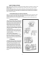
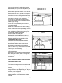
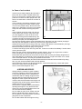
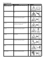
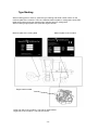
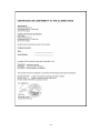
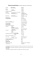
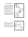
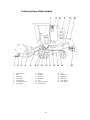
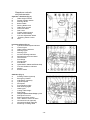
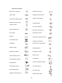
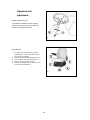
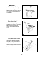
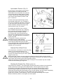
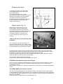
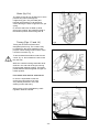
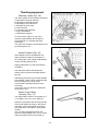

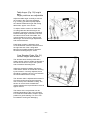
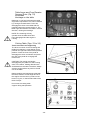

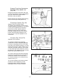
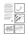
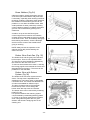

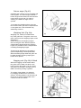
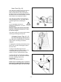
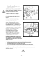
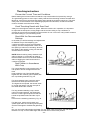


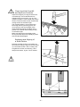

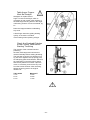
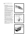
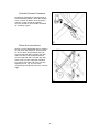


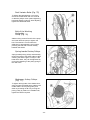

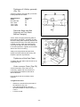
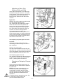
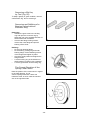
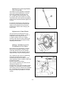

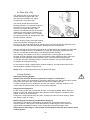
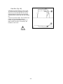
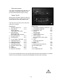


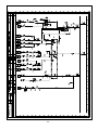

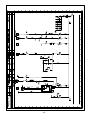
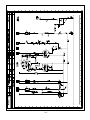
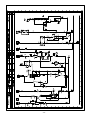

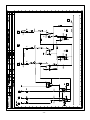
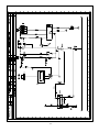
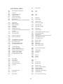
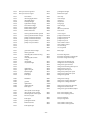
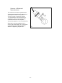


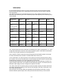
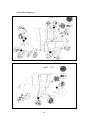

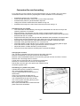
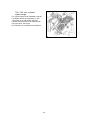


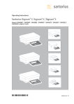


![DGID Software [EN]](http://vs1.manualzilla.com/store/data/005717670_1-65b44a14cec330296683d17d94da3fca-150x150.png)