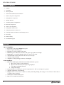
1
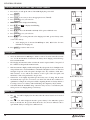
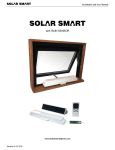
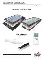
INSTALLATION & USER MANUAL
MODELS EVMS & GSVMS
with Rain Sensor
800-388-0293 Fax: 207-216-4562 [email protected] www.wascoskylights.com
Eastern Facility: 85 Spencer Drive, Unit A, Wells, ME 04090 Western Facility: 6645 Echo Avenue, Reno, NV 89506
INSTALLATION & USER MANUAL
Installation and User Manual
TABLE OF CONTENTS
21 Features
Features
In Box
The Box
32 In The
Items Required
42 BasicFurther
Operation
3
Basic Operation
5 Solar Panel and Rain Sensor Installation
4
Solar Panel and Operator Installation
6 Remote Setup and Configuration
4
Operator Installation
75 Pairing Remote
to Operator
Solar Panel
and Rain Sensor Installation
the Solar Panel and Rain Sensor to the Operator
86 MultipleWiring
Remotes
Remote
Setup Configuration
and Configuration
87 Secondary
Remote
8
Pairing Remote to Operator
10 Rain Sensor Operation
9
Multiple Remotes
11 Time to Close Operation
9
Secondary Remote Configuration
12
Setting
MAX-OPEN
Limit
11
Rain Sensor Operation
12 Setting
Time
to Close Operation
13
Temperature
Control (TC)
13 Checking
Setting
MAX-OPEN
Limitand Charging Current
14
STATUS
of Batteries
14
Setting Temperature Control (TC)
15 Re-Zoning
15
Checking STATUS of Batteries and Charging Current
16 Remote Display
16
Re-Zoning
17
Tips
18 Troubleshooting
Remote Display
18
Troubleshooting Tips
FEATURES
Operator Highlights:
1. Powered by a solar charged NiMH battery pack.
2. End-user replaceable battery pack.
3. Operating force rating of 60 lbs at the chain.
4. Maximum opener chain travel of 8 inches with option to program various lengths.
5. Bright White cover standard. Paintable surface for custom color match.
6. Attachment link on chain is fastened to the sash by a release pin.
7. AC trickle charger included.
8. Adaptable to awning and hopper windows, and skylights.
Remote Highlights:
1. Large and readable display with bi-directional feedback from the operator:
a. Open / Close status percentage displayed.
b. Operator and remote battery level percentage displayed.
c. Solar charge rate displayed in mA.
d. Temperature display.
2. 9 programmable zones with up to 9 operators assigned per zone. Able to control up to 81 operators.
3. Automatic temperature control function.
4. Multiple remotes can be used on a Main / Secondary relationship. Pairing and settings can be sent from a main remote to
secondary remotes wirelessly.
5. Stand-up base with wall mount option.
6. Remote uses standard (2) AA batteries.
1
2
Revision 8.12.2015
Solar Smart
Operator
INSTALLATION
& USER
MANUAL
Installation and User Manual
IN THE BOX
• Solar Smart Operator
• operator battery cover
• operator battery
• chain clip with release pin
• small flat head screw driver
•
•
•
•
remote
remote battery cover
(2) AA batteries
wall mount attachment
•
•
•
•
•
•
•
solar panel with wiring pigtail
rain sensor with wiring and bracket
AC trickle charger
stainless steel mounting bracket
(2) stainless steel bracket tabs
(4) stainless steel bolts
(4) stainless steel nuts
FURTHER ITEMS REQUIRED
• (5) fasteners for mounting the operator
• (2) fasteners for mounting the chain clip
• (4) fasteners for mounting the solar panel and bracket
DO NOT INSTALL THE BATTERIES
UNTIL DIRECTED TO DO SO
Revision 8.12.2015
3
2
INSTALLATION & USER MANUAL
Installation and User Manual
BASIC OPERATION
•
Using the operator requires that it has been paired to the remote. Refer to Initial Remote Setup and Configuration.
Opening and Closing of an Operator
1.
Press any key to wake up the remote, if the LCD display has powered off.
2.
Press ZONE to choose a single zone (1 thru 9) of operators or ALL to operate all operators in all zones.
3.
Press OPEN or CLOSE to open or close the window/skylight.
4.
Press OPEN or CLOSE during operation to STOP the operator at any time.
Enable / Disable Automatic Functions
1.
Press and hold AUTO to show or remove AUTO from the display, thus enabling or disabling the temperature control
(TC) or Time-to-Close (P1) functions.
3
4
Revision 8.12.2015
INSTALLATION & USER MANUAL
Installation and User Manual
Installation and User Manual
ON of the SOLAR
INSTALLATION
PANEL andofRAIN
the SOLAR
SENSOR
PANEL and RAIN SENSOR
panel must •be The
mounted
solarwith
panelairspace
must be mounted with airspace
for cooling and
performance
underneath
efficiency;
for cooling
as
and
efficiency;
NOTE:
The skylight
needs
to performance
be installed on
the roofas
before attaching the solar panel.
intain the product life
wellspan.
as maintain the product life span.
1. 1.
Review
the
separate
instructions
e solar panel face
down
Layonthe
a flat
solar
surface.
panel face
down on for
a flatmotor
surface.
operation
and not
open
the skylight
fully
with the
are not to scratch the
solar
Takepanel.
care
to scratch
the solar
panel.
two stainless steel 2.
nutsInsert
into
the
twochannel
stainless
ofsteel nuts into the channel of
remote
control.
rimeter frame;2.oneConnect
each
theon
perimeter
thesolar
twopanel
frame;
shortto one
eachon
onthe
theexterior
two short
the
the wire
sides.
of the
skylight at the low side. The connector can
wo stainless steel 3.
boltsUse
to two
attachstainless
the twosteel bolts to attach the two
only go together one way and will ‘click’ when
t tabs to the frame bracket
with thetabs
twotonuts
the frame with the two nuts
locked together.
d into the channel. Doinserted
not fullyinto
tighten
the channel.
at
Do not fully tighten at
3. Locate the solar panel on the skylight frame as
me.
this time.
shown below, centered side to side. Install the
e remaining stainless
4. steel
Usebolts
the remaining
and nuts to
stainless steel bolts and nuts to
panel
with
the
screws
supplied.
the mounting bracket toattach
the solar
the mounting
panel. bracket to the solar panel.
4. 5.
Close
the skylight
the bracket
installation.
the solar panel
and Install
bracket
theonsolar
toto complete
the
panel and
on to the
or of the building exterior
near the ofoperator
the building near the operator
ation location.
installation location.
nd rotate the solar6.panel
Tilttoand
maximize
rotate the
thesolar panel to maximize the
panels exposure to the
solar
Sun.
panels
Alignment
exposure to the Sun. Alignment
ds the southern sky istowards
recommended
the southern
for sky is recommended for
locations in North most
America
locations
for best
in North America for best
ure to mid-day sun.
exposure to mid-day sun.
n all the fasteners 7.
to secure
Tighten
theall
solar
thepanel
fasteners to secure the solar panel
ation.
orientation.
and waterproof the
8. pigtail
Route wiring
and waterproof
to the
the pigtail wiring to the
r of the building where interior
the operator
of theisbuilding
to be where the operator is to be
ed.
installed.
the rain sensor and9.bracket
Installonthe
therain
exterior
sensor and bracket on the exterior
l as possible near the operator.
as level as possible near the operator.
and waterproof the
10.wiring
Routetoand
thewaterproof
interior the wiring to the interior
the operator will be installed.
where the operator will be installed.
y recommended
• to
It is
only
highly
use recommended
the wiring
to only use the wiring
or the solar panel and
provided
rain sensor.
for the solar panel and rain sensor.
sion 8.12.2015
5
5
Revision 8.12.2015
INSTALLATION & USER MANUAL
Installation and User Manual
INITIAL REMOTE SETUP and CONFIGURATION
•
The following are applicable for configuring the main remote only. To configure additional remotes, refer to 'Multiple
Remotes' for more information.
NOTE:
The remote
been
by Wasco.
forZONE
future
use.
Installation
andALL.
User Manual
• Pressing
MODEhas
does
notconfigured
work whenand
zonepaired
in remote
displayKeep
is set instructions
to ALL. Press
to exit zone
• All steps must be performed within 30 seconds or the remote control will default to the previous settings.
INITIAL REMOTE SETUP and CONFIGURATION
1.
•
2.
•
•
3.
1.
4.
5.
2.
3.
6.
4.
7.
5.
Open the remote battery cover and install the two AA alkaline batteries and replace
The following are applicable for configuring the main remote only. To configure additional remotes, refer to 'Multiple
the cover.
Remotes' for more information.
All
the screen
display
segments
be visible
thedisplay
remoteisruns
a self-test
whichZONE to exit zone ALL.
Pressing
MODE
does
not workwill
when
zone inwhile
remote
set to
ALL. Press
lasts
for amust
few seconds.
Afterwithin
which,30SET
will
All steps
be performed
seconds
or be
thedisplayed.
remote control will default to the previous settings.
Press ▲ ▼ to choose either C (Celsius) or F (Fahrenheit).
Open the remote battery cover and install the two AA alkaline batteries and replace
Press ENTER to save your selection.
the cover.
Press ▲ ▼ to choose either M (main) or S (secondary). Select M for main.
All the screen display segments will be visible while the remote runs a self-test which
Note: Secondary is only used when using additional remotes. Refer to 'Multiple
lasts for a few seconds. After which, SET will be displayed.
Remotes' for more information.
Press ▲ ▼ to choose either C (Celsius) or F (Fahrenheit).
Press ENTER to save your selection.
Press ENTER to save your selection.
ZONE ALL and the temperature should now be displayed.
Press ▲ ▼ to choose either M (main) or S (secondary). Select M for main.
Note: Secondary is only used when using additional remotes. Refer to 'Multiple
Remotes' for more information.
7
6
6.
Press ENTER to save your selection.
7.
ZONE ALL and the temperature should now be displayed.
Revision 8.12.2015
Solar Smart
Operator
INSTALLATION
& USER
MANUAL
Installation and User Manual
PAIRING the REMOTE to the OPERATOR
•
•
•
•
•
Pairing sets up communication between the remote and the operator.
The remote will be able to control all operators assigned within a single zone simultaneously, or control all zones at once.
There are 9 zones (1 thru 9), with each zone containing 9 ID numbers (1 thru 9). Each operator will need to be assigned
to a zone and ID number. Each zone and ID number combination can only be assigned one operator.
The following instructions are applicable to pairing the first and additional operators to a single remote.
Each operator can only be paired with one main remote, however multiple secondary remotes may be used once setup and
configured.
The Operator
•
The remote will need to be paired within 2 minutes, or the operator will default back to the previous settings.
1.
Remove the battery cover from the operator. If
connected, disconnect the battery connector from
the operator circuit board, for at least 30 seconds.
NOTE: The Solar Panel
disconnected at this time.
2.
must
also
be
Connect the battery connector to the operator circuit
board, pressing firmly until the plug is locked into
place.
3.
The red light on the circuit board will continually
blink while it is in pairing mode.
The Remote
1.
Press any key to wake up the remote, if the display has powered off.
2.
Press and hold the MODE , release when PAIR SET is displayed.
3.
Press ZONE as necessary to choose the appropriate zone (1 thru 9).
4.
Press ENTER to save your selection.
5.
Press ▲ ▼ to choose the ID number (1 thru 9) within the zone. ID numbers
already in use will not be displayed.
6.
Press ENTER to save your selection. The remote will attempt to pair to the
operator.
(continues on next page)
Revision 8.12.2015
7
8
INSTALLATION & USER MANUAL
7.
Installation and User Manual
SUCC will be displayed to indicate a successful pairing. The operator will then
fully open then close one cycle. DO NOT press any buttons on the remote until
this cycle completes.
a.
If a FAIL message is displayed, press ENTER on the remote to try to
pair again.
b.
If a FAIL message is displayed again, ensure that the operator is in
pairing mode. If the red light is not still blinking, disconnect and
reconnect the battery connector on the operator and repeat steps 1-7
again.
MULTIPLE REMOTES
•
•
•
It is intended that one or multiple operators may be controlled from multiple secondary remotes. This is done by sending the
pairing and settings stored in the first configured M (main) remote, to the additional S (secondary) remote(s). Secondary
remotes will be 'copies' of the main.
Any changes to operator zones, ID numbers, and/or adding additional operators can only be performed using the main remote.
The changed settings would then need to be re-sent from the main to the secondary remote(s).
Ensure that a main remote has been configured as outlined in 'Remote Setup and Configuration' and that it has been paired to
the operator(s) as described in 'Paring Remote to Operator.'
Secondary Remote Configuration
•
All steps must be performed within 30 seconds or the remote control will default to the previous settings.
1.
Open the remote battery cover; remove and reinstall two AA alkaline batteries and
replace the cover.
2.
All the screen display segments will be visible while the remote runs a self-test which
lasts for a few seconds. After which, SET will be shown on the Display to indicate
input is required.
9
8
3.
Press ▲ ▼ to choose either C (Celsius) or F (Fahrenheit).
4.
Press ENTER to save your selection.
5.
Press ▲ ▼ to choose either M (main) or S (secondary). Select S for secondary.
6.
Press ENTER to save your selection.
7.
ZONE ALL and the temperature should now be displayed.
Revision 8.12.2015
Solar Smart
Operator
INSTALLATION
& USER
MANUAL
1.
Installation and User Manual
SECONDARY REMOTE STEPS
a.
Press and hold MODE , release when PAIR SET
is displayed and the S in
the upper-right corner is flashing.
b.
Press ENTER . The secondary remote will now be waiting to receive the
transmission from the main remote. It will wait for 30 seconds.
2.
MAIN REMOTE STEPS
a.
Press and hold MODE , release when PAIR SET is displayed.
b.
Press MODE twice to move past RE-ZONE to display M in the upper-right
corner as flashing.
c.
Press ENTER to begin transmitting the settings to the secondary remote.
d.
SUCC will be displayed on a successful transfer of settings.
i.
If a FAIL message is displayed instead, be sure that the secondary remote is
still
configured
to
be
waiting
to
receive
the
transmission.
Press ENTER to retry.
Revision 8.12.2015
9
10
Installation and User Manual
INSTALLATION & USER MANUAL
RAIN SENSOR
The rain sensor should be installed horizontally, with a slight tilt to prevent water from pooling. The sensor location depends on many
factors. The key to proper installation is that the sensor must be level and exposed when the operator opens the unit. The wires from
the sensor to the operator must be ran to the operator in a water proof manner so as to not induce water penetration that could damage
the interior. The sensor is not polarity sensitive so it does not matter which wire goes to which connector in the operator.
By default, the rain sensor is enabled when the remote is initially paired to the operator regardless of whether the rain sensor is attached
or not. When the rain sensor is enabled a small
1.
umbrella will be displayed in the top right hand display box.
To enable or disable the rain sensor, press any key to wake up the remote if the LCD
display has powered off.
2.
Press MODE .
3.
Press ZONE as necessary to choose the desired zone.
4.
After the desired zone is flashing, press ENTER .
5.
MAX-OPEN will know be flashing.
6.
Press ▲ ▼ until the
7.
Press ▲ ▼ to choose the ID number (1 thru 9) within the zone.
8.
Press ENTER to confirm your selection.
9.
Press ▲ ▼ to choose between ON and OFF while they are flashing.
icon is displayed and flashing, press ENTER .
10. Press ENTER to save your setting.
11. LCD displays steady ON or OFF for one second, then SUCC for 2 seconds, indicating
success. Press MODE a few times to return to the home screen
a.
If setting not successful, LCD displays FAIL for 1 second, then returns to the
same step #8 to retry setting.
RAIN SENSOR OPERATION
When a drop of water is on the sensor the operator may not react immediately. The control system actually takes multiple
reading in an effort to avoid false readings and possible “cycling” of the operator before it sends the close or open commands.
If the operator is manually opened when the rain sensor is enabled AND there is water present on the sensor, the
operator will close and the
umbrella icon will blink on the Remote. If you desire to open the operator at this time, the
sensor will need to be disabled before it will stay in the open position.
If the Rain Sensor and the Automated Temperature Control are enabled at the same time, the Rain Sensor will take precedence
over the Temperature Control. In other words, if rain is detected, the operator will close regardless of the temperature until
such time as water is no longer detected on the sensor before it will automatically re-open.
As noted above, the rain sensor is designed to detect a lowering of the resistance between the metallic strips on the sensor. The
resistance can be lowered by a number of factors including moss, sap, heavy dew, or condensation drops from surrounding
structures. Therefore it is important to periodically clean the sensor to maintain proper operation. If all operations function
properly except when the Rain Sensor is enabled, cleaning the Rain Sensor is recommended.
11
10
Revision 8.12.2015
Solar Smart
Operator
INSTALLATION
& USER
MANUAL
Installation and User Manual
TIME TO CLOSE
The Time to Close (P1) function will automatically close the operator after a user defined time period. The user selected time
period is in 10 minute increments from 0 to 1 hour. From 1 to 24 hours, the increments change to 30 minutes.
1.
Press any key to wake up remote, if the LCD display has powered off.
2.
Press MODE - the LCD should display SET, and ZONE should be flashing.
3.
Press ZONE as necessary to choose the appropriate zone (1-9).
4.
When the correct zone is flashing, press ENTER
5.
MAX-OPEN will be displayed and flashing.
6.
Press ▲ ▼ until P1 is displayed and flashing.
7.
Press ENTER .
8.
Press ▲ ▼ until the desired Time To Close is displayed and flashing or NULL to
turn function off.
9.
Press ENTER .
10. ST is now displayed and flashing. Press MODE to return to the home screen OR
press ▲ ▼ to scroll and set other features.
11. The Time To Close selection will be retained in memory until changed by the user.
However, you must activate the AUTO feature for either the Time To Close or the
Temperature Control (TC) function for it to operate. NOTE: The Time To Close and
Temperature Control cannot be enabled simultaneously for the same zone.
Enable / Disable the TIME TO CLOSE Function
1.
To activate the AUTO function you must start in the Home screen.
2.
Press and hold the AUTO button for 2 seconds until the screen changes. The screen
will read either AUTO/TC, AUTO/P1, or be blank which disables both automatic
functions. Each time you press and hold the AUTO button for 2 seconds it will scroll
the screen to the next option. When the correct Auto Function is displayed, you are
done.
3.
When the Auto function is enabled, it will stay enabled until it is turned off.
Revision 8.12.2015
11
12
INSTALLATION & USER MANUAL
Installation and User Manual
SETTING MAX-OPEN LIMIT
•
•
The travel distance that the operator(s) will open a window/skylight (MAX-OPEN) can be reduced for all operators within a
zone; and each zone may have a unique MAX-OPEN value. This may be beneficial to prevent rain or excess wind from
entering when the operator(s) is open.
The factory setting MAX-OPEN limit is set to open up to 80% of full open position.
1.
Press any key to wake up the remote, if the LCD display has powered off.
2.
Press MODE .
3.
Press ZONE as necessary to choose the appropriate zone 1 thru 9.
4.
Press ENTER to save your selection.
5.
MAX-OPEN will be displayed and flashing.
6.
Press ENTER .
7.
Press ▲ ▼ to set the percentage, in increments of 10%.
8.
Press ENTER to save your setting.
9.
TC is now displayed.
10. Press MODE to return to the home screen - OR - to continue on to set the Temperature
Control (TC).
13
12
Revision 8.12.2015
Solar Smart
Operator
INSTALLATION
& USER
MANUAL
Installation and User Manual
SETTING TEMPERATURE CONTROL (TC)
•
•
•
•
Automated temperature control (TC) can be set for all operators within a zone; and each
zone may have a unique TC value.
When set and the remote is set to AUTO, the temperature control will open the operator(s)
within a zone when the temperature setting is reached.
It will close the operator(s) when the temperature drops greater than 5 degrees (F) or 2
degrees (C) below the set level.
This automatic function is based on the temperature at the remotes location and must be
maintained for approximately 5 minutes.
1.
Press any key to wake up the remote, if the LCD display has powered off.
2.
Press MODE .
3.
Press ZONE as necessary to choose the appropriate zone (1 thru 9).
4.
Press ENTER to save your selection.
5.
MAX-OPEN will be displayed and flashing.
6.
Press ▲ ▼ until TC is displayed and flashing.
7.
Press ENTER .
8.
Press ▲ ▼ to set the desired temperature, or NULL to turn function off, for this zone.
9.
Press ENTER to save your selection.
•
The temperature in which the operator will run has now been set. Next, a MAX-OPEN
limit is set specifically for when the TC function opens the operator. This MAX-OPEN
cannot exceed the limit set for basic operation.
10. Press ▲ ▼ to set the percentage, in increments of 10%, of the temperature controlled
MAX-OPEN.
Operator(s)
will
not
open
past
MAX-OPEN
set
above.
Press ENTER to save your setting.
11. P1 is now displayed.
12. Press MODE to return to the home screen - OR - to continue on to check the status of the
batteries and charge current.
•
After any change to the TC settings, the TC function will be enabled and AUTO will be
displayed.
Enable / Disable the TC Function
1.
Press and hold the AUTO button for 2 seconds until the screen changes. The screen
will read either AUTO/TC, AUTO/P1, or be blank which disables both automatic
functions. Each time you press and hold the AUTO button for 2 seconds it will scroll
the screen to the next option. When the correct Auto Function is displayed, you are
done.
Revision 8.12.2015
13
14
INSTALLATION & USER MANUAL
Installation and User Manual
CHECKING STATUS OF BATTERIES AND CHARGING CURRENT
1.
Press any key to wake up the remote, if the LCD display has powered off.
2.
Press MODE .
3.
Press ZONE as necessary to choose the appropriate zone (1 thru 9).
4.
Press ENTER to save your selection.
5.
MAX-OPEN will be displayed and flashing.
6.
Press ▲ ▼ until ST is displayed and flashing.
7.
Press ENTER .
8.
Press ▲ ▼ to choose the ID number (1 thru 9) of the operator within the zone.
9.
Press ENTER to save your selection.
10. Press ▲ ▼ to cycle viewing either the solar charging rate in mA, operator battery status,
or the remote battery.
•
Solar charging rate is measured in Milliampere (mA). Refer below for more
information on charging rate.
11. Press MODE to return to main screen.
Charging Rate
•
•
•
•
•
mA is the abbreviation for Milliampere, which is a unit of electrical current flow. In this
case, it is the measurement of current into the battery when charging, and it will range
between 0 and 150 mA.
The charging measurement is taken each time the status is requested and is a 'snap shot' of
the conditions at that particular moment in time.
This measurement is highly variable and depends directly upon the level of sunlight on the
solar panel. Be aware of external influences which affect the light level, these are: direction
and angle of exposure of the solar panel to the light source, sky conditions, clouds, man made structures or trees which cause shadows on all or part of the solar panel, and
maintenance of the solar panel itself, to keep it clean.
Current flow is also highly dependent upon the battery state of charge and the status
measurement may report zero or low mA, even when solar and all other conditions are
optimum. For example, the solar panel could be outputting 40 mA on a battery that has a
low charge, however on a battery with near full charge the output may only be 10 mA.
Solar Smart limits the maximum charge current for safety reasons, to extend battery life,
and to prevent over-charging damage to the battery.
Battery Alerts
•
•
Remote Battery Status
Solar Charging Rate
The
icon will be displayed on the remote when the remote batteries are in need of
replacement.
The
icon will be displayed when the operator battery is low. When the operator
battery is critically low, the operator will be allowed to close; however will not be able to
open until the battery is recharged to a sufficient level.
Operator Battery Status
15
14
Revision 8.12.2015
Solar Smart
Operator
INSTALLATION
& USER
MANUAL
Installation and User Manual
RE-ZONING
•
•
•
Recommended only for when multiple operators are used with a single remote.
This process removes the operator from the assigned zone and/or ID number, but remains
paired to the remote. The operator then is reassigned to a new zone and/or ID number on
the same remote.
CAUTION - If this is not done correctly, you will have to re-pair the Remote to the
Operator, which would involve unplugging the Operator's battery. Please read these
instructions carefully first, before performing this operation.
1.
Press any key to wake up the remote, if the display has powered off.
2.
Press and hold MODE , release when PAIR SET is displayed.
3.
Press MODE again to display RE-ZONE.
4.
Press ZONE as necessary to choose the appropriate zone (1 thru 9) of the operator to be
moved to another zone.
5.
Press ENTER to save your selection.
6.
Press ▲ ▼ to choose the ID number (1 thru 9) within the zone in which the operator is
assigned to.
7.
Press ENTER to save your selection.
8.
SUCC will be displayed. The operator will now be unassigned from the previous zone and
ID number. DO NOT STOP HERE, steps 8, 9 and 10 must be completed.
a.
9.
Press ENTER to retry, if a FAIL message is displayed instead.
Press ZONE to choose the new zone (1 thru 9) the operator shall be assigned to.
10. Press ENTER to save your selection.
11. Press ▲ ▼ to choose the ID number (1 thru 9) within the zone in which the operator shall
be reassigned to.
12. Press ENTER to save your selection.
13. SUCC will be displayed. The Operator will run through an entire open and close cycle.
Revision 8.12.2015
15
16
Installation and User Manual
INSTALLATION & USER MANUAL
REMOTE DISPLAY
TROUBLESHOOTING TIPS
1.
If in AUTO mode and operator(s) is not working as expected, make sure none of the secondary remotes are set to AUTO mode
and that temperature control (TC) for all zones on secondary remotes are set to NULL.
2.
MAX-OPEN can be set to different values on both the main and secondary remotes. The operator will open to the MAX-OPEN
setting of the remote used to open it. If the operator is not opening the proper amount be sure to check that MAX-OPEN is set
properly on the remote used.
3.
Temperature control (TC) may also have to be set to have a lower MAX-OPEN value than the otherwise set MAX-OPEN.
4.
Temperature change must be maintained for 10 minutes before the temperature control (TC) function will operate.
For more Trouble Shooting Tips, please visit www.SolarSmartOpener.com
ADVANCED SERVICE OPERATIONS
RESET OF REMOTE TO FACTORY SETTINGS
1.
Press any key to wake up the remote, if the display has powered off.
2.
Press and hold MODE , release when PAIR SET is displayed.
3.
Press MODE again to display RE-ZONE.
4.
Press MODE to display M in the upper-right corner as flashing.
5.
Press ENTER FAIL is displayed as flashing.
6.
Press and hold MODE , release when rF TEST is displayed.
7.
Press MODE repeatedly until rET FAC is displayed.
8.
Press ENTER , all the screen display segments will be visible while the remote runs a self-test which lasts for a few seconds.
After which, SET will be displayed.
The remote has now been reset to factory settings; it is no longer paired to any operators.
17
16
Revision 8.12.2015
Solar Smart
Operator
INSTALLATION
& USER
MANUAL
Installation and User Manual
Please record your Remote settings for ease of reference as well as assist in troubleshooting.
ZONE
1
2
3
4
5
ID
1
2
3
4
5
6
7
8
9
1
2
3
4
5
6
7
8
9
1
2
3
4
5
6
7
8
9
1
2
3
4
5
6
7
8
9
1
2
3
4
5
6
7
8
9
Location
ZONE
6
7
8
9
ID
Location
1
2
3
4
5
6
7
8
9
1
2
3
4
5
6
7
8
9
1
2
3
4
5
6
7
8
9
1
2
3
4
5
6
7
8
9
Revision 8.12.2015
17
18