1
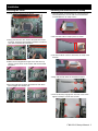
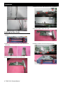
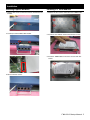
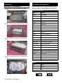
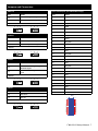
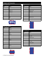
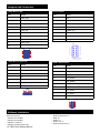
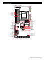
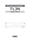
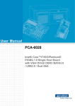
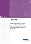
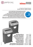
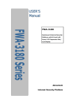
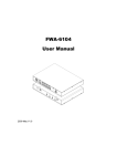
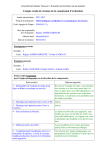
FWA-3210A/B 1RU Network Application Platform x86-based Intel®
XeonTM E3 series and 2nd generation Core™ i7/i5/i3 processors
Startup Manual
Specifications
Packing List
Before installation, ensure that the following materials have
been received:
• One FWA-3210 Internet Security Platform
• One box of accessories
• One warranty certificate
If any of these items are missing or damaged, please contact your distributor or sales representative immediately.
Note: Acrobat Reader is required to view any PDF file.
Acrobat Reader can be downloaded at: www.
adobe.com/Products/acrobat/readstep2. html
(Acrobat is a trademark of Adobe)
Main Board Functions
• CPU: Intel® Xeon E3-1225/ E3-1275 (FWA-3210A only),
and 2nd gen. Core™ i7-2600/i5-2400(FWA-3210B only),
i3-2120, Pentium®-G850, Celeron®-G540 Processors
• Chipset: Intel® C206 PCH/ H61 PCH
• BIOS: AMI™
• Memory: Dual channel DDR3 1333/1066 MHz ECC
(Xeon® processors only) Un-buffered memory, up to
32GB (FWA-3210A) /16GB(FWA-3210B)
• Ethernet: 6 x Intel® 82574L 10/100/1000 Mbps Ethernet
with optional 3 segment bypass
• PCIe Bus:
-1xGen2, PCI-E x8 gold finger support NMC module
-1xGen2, PCI-E x8 or 2 x4 Add-on Card slot (C206 only)
• C-Fast Interface: 1 x C-Fast Socket
• Storage: 1 x 3.5”or 1 x 2.5” internal HDD / SSD
• Peripherals:
-USB
2 x USB2.0 ports on front panel
-Serial
1 x front console port RJ45
-LCD Module 1 x2 character display
• Dimensions(W x L x H): 430mmx500mmx44mm
• Weight: 10Kg
• Environment: Operating
Non-operating
• Temperature: 0°C~ 40°C
-20°C ~ 75°C
(32°F~104°F)
(-4°F~167°F)
• Humidity: 5% ~ 85% @40°C(104°F) 5% ~ 95%
For more information on this and other Advantech
products, please visit our website at:
http://www.advantech.com.tw/support
http://www.advantech.com.
For technical support and service, please visit our
support website at:
http://www.advantech.com/support
This manual is for the FWA-3210 series Rev. A
Part No. 2002321000
Printed in China
1st Edition,
Jan. 2012
FWA-3210 Startup Manual 1
Specifications
Express Modules
FWA-3210A Redundant
• Interface:
- GbE Express Module:
Supports 4 ports 10/100/1000 Base-T copper module
Supports 4 ports 10/100/1000 Base-X SFP module
- 10GE Express Module:
Supports 2 ports 10 GbE Base-F SFP+ module
• Controller:
- GbE Express Module
2 x Intel® 82576 Dual Port GbE controllers
- 10GbE Express Module:
1x Intel® 82599 2-port 10 GbE controller
• Dimensions (W x D): 72 x 172 mm
Front view
Figure 1: NMC-0103 4-port RJ45 GE Module
Back View
FWA-3210B Single PSU
Front view
Figure 2: NMC-0102 4-port SFP GE Module
Figure 3: NMC-1001 2 ports SFP+ 10GE Module
2 FWA-3210 Startup Manual
Back View
Installation
Installing the CPUs
Installing the heatsink and air scoop
1. Locate the CPU sockets on the board.
1. Unwrap heatsink and black Mylar air scoop. There are
two threaded holes on each side of the heatsink that
accommodate the air scoop screws.
2. Put heat sink and air scoop in place as shown.
2. Taking one CPU at a time, remove the protective shield,
if present, and press the load lever and move it out till it is
clear of the retention tab, and raise it.
3. Use the four black screws to attach the air scoop to the
heatsink.
3. Make sure that alignment triangle on the CPU lines up
with the correct corner on the socket, and ease the CPU
into place.
4. Align and carefully lower the heatsink into place.
4.Close the load plate and push the load lever back down
until it engages the retention tab.
5. Insert and loosely engage each heat sink screw. Then
tighten carefully to secure the heat sink.
FWA-3210 Startup Manual 3
Installation
4. Release the screws and remove the riser card bracket.
5. Install the add-on card to riser card.
Installing the Riser Cards
1. Release four screws from chassis base and take out the
bracket.
2. Release the first IO bracket screw and remove the first
IO bracket.
3. Install the add-on card and secure with screw.
4 FWA-3210 Startup Manual
6. Replace brackets and secure firmly with screws.
Installation
Installing Express Modules
Installing 3.5” HDD Modules
1. Release two screws on the base chassis and remove the
bracket.
1. Release the four screws and remove 3.5” HDD bracket.
2. Carefully install the NMC-10xx module.
2. Install one 3.5” HDD on the bracket with four screws.
3. Install 3.5” HDD module on the base chassis with four
screws.
3. Secure with two screws.
FWA-3210 Startup Manual 5
Installation
Installing 2.5” HDD Modules
1. Please release four screws and remove 2.5” HDD
bracket.
Jumpers and Connectors
The board has a number of jumpers that allow you to configure your system to suit your application. The table below
lists the function of each of the jumpers and connectors.
Jumper/Connector list
2. Install the first 2.5” HDD in the bracket with four screws.
3. Install the second 2.5” HDD in the bracket with four
screws.
4. Install 2.5” HDD module on the base chassis with four
screws.
Label
Function
CMOS1
Clear CMOS
JWDT1~4
Short watchdog
JVGPIO1
Short GPIO power
JUART1
Short selection BMC
PSON1
Short ATX
LPT1
Parallel port
USB34
Internal USB
VGA1
VGA connector
COM2
Serial port
LPC1
Debug port
KBMS1
PS2 Keyboard/Mouse
SYSFAN1~4
FAN connector
SATA_PWR1
5V SATA power connector
SYS_RST1
Reset system button
PWR_BTN1
System power on/off button
HDD_LED1
HDD LED pin header
PWR_LED1
5V power led pin header
JCASE1
Case open connector
Status_LED1~3
LAN1-2~LAN5-6 Bypass status LED
BP_Force1~3
LAN1-2~LAN5-6 Bypass force button
JTAG1
Burn in data
JTAG2
Burn in CPLD data
FP1
Front panel
GPIO1
GPIO function
CMOS1
Pins
Result
1-2
Normal*
2-3
Clear CMOS
*: Default
1
2
3
Keep CMOS data*
6 FWA-3210 Startup Manual
1
2
3
Clear CMOS data
Jumpers and Connectors
JWDT1~4
LPT1: Parallel port (for LCM module usage)
Pins
Result
Pins
Result
1-2
Short watchdog is WDT_OUT1~4_N*
1
PIO_STB
2-3
Short watchdog is WDT_OUT0_N
2
#AFD
3
PIO_PD0
4
#ERR
5
PIO_PD1
6
#INIT
7
PIO_PD2
*: Default
1
2
3
1
2
3
JVGPIO1
Pins
Result
8
#SLIN
1-2
Short GPIO power +V5_SB*
9
PIO_PD3
2-3
Short GPIO power +V3.3_SB
10
GND
11
PIO_PD4
12
GND
13
PIO_PD5
14
GND
15
PIO_PD6
Result
16
GND
1-2
Short selection BMC_UART_
SWTCH# signal*
17
PIO_PD7
18
GND
2-3
Short selection BMC_DETECT#
signal
19
#ACK
20
GND
21
BUSY
22
GND
23
PE
24
GND
25
SLCT
26
GND
*: Default
1
2
3
1
2
3
JUART1
Pins
*: Default
1
2
3
1
2
3
PSON1
Pins
Result
2-3
Short ATX*
1-2
Short AT
LPT1
*: Default
1
2
3
1
2
3
1
3
5
7
9
11
13
15
17
19
21
23
25
2
4
6
8
10
12
14
16
18
20
22
24
26
FWA-3210 Startup Manual 7
Pins
Result
1
USBV1
1
GND_F
2
USBV1
2
NC
3
USB9_z_P-
3
SERIAL2_DTR
4
USB9_z_P-
4
SERIAL2_RI
5
USB9_z_P+
5
SERIAL2_TXD
6
USB9_z_P+
6
SERIAL2_CTS
7
GND
7
SERIAL2_RXD
8
GND
8
SERIAL2_RTS
9
GND
9
SERIAL2_DCD
10
SERIAL2_DSR
8
Result
6
COM2: Serial port
Pins
4
Internal USB port3,4
2
Jumpers and Connectors
USB34
9
7
5
3
1
COM2
VGA1: VGA connector
9
10
7
8
5
6
3
4
1
2
Pins
Result
1
VGA_R
2
CRT_VCC
LPC1: Debug port
3
VGA_G
Pins
Result
4
GND
1
LPC_FRAME#
5
VGA_B
2
GND
6
N/C
3
LPC_AD0
7
N/C
4
CLK33M_LPC0
8
V_SDAT
5
LPC_AD1
9
GND_V
6
PCI_SERIRQ
10
HSYNC
7
LPC_AD2
11
GND_V
8
PLTRST_SIO#
12
VSYNC
9
LPC_AD3
13
GND_V
10
+V3.3
14
V_SCLK
15
GND_V
WB_5x2V_2.00mm
LPC1
8 FWA-3210 Startup Manual
BH_8x2V_2.00mm
1
3
5
7
9
11
13
15
2
4
6
8
10
12
14
16
VGA1
9
10
7
8
5
6
3
4
1
2
Jumpers and Connectors
KBMS1: PS2 Keyboard/Mouse
PWR_BTN1: System power on/off button
Pins
Result
Pins
Result
1
MSCK
1
FP_PANSWIN#
2
KBMS_VCC
2
GND
3
GND
4
MSDT
5
KBDT
6
KBCK
1
2
HDD_LED1: HDD LED pin header
6
5
4
3
2
1
KBMS1
Pins
Result
1
VCC
2
SATA_LED
1
2
SYSFAN1~4: FAN connector
Pins
Result
1
GND
2
+12V
3
FAN_SPEED0
4
FAN_PWM
PWR_LED1: 5V power led pin header
Pins
Result
1
+V5
2
GND
1
2
4
3
2
1
SYSFAN1
W_4V_2.54mm
SATA_PWR1: 5V SATA power connector
JCASE1: Case open connector
Pins
Result
1
CASEOP#
2
GND
Pins
Result
1
+V5
2
GND
3
GND
LED1~3: LAN1-2~LAN5-6 Bypass status display
4
+V12
Pins
Result
1
RELA_ON_0# /1# /2#
2
RELA_ON_0/1/1
1
2
4
3
2
1
SATA_PWR1
1
2
SYS_RST1: Reset system button
Pins
Result
1
SRST_IN#
2
GND
1
2
BP_FORCE1~3: LAN1-2~LAN5-6 Bypass force button
Pins
Result
1
BTN_SW1/SW2/SW3
2
+V3.3A
1
2
FWA-3210 Startup Manual 9
Jumpers and Connectors
JTAG1: Burn in data
FP1 front panel
Pins
Result
Pins
Result
1
JTAG_TCK
1
+V5
2
+V3.3
2
GND
3
JTAG_TMS
3
Power button
4
GND
4
SYSTEM RESET
5
JTAG_TDI
5
SMBUS CLK
6
GND
6
SMBUS DATA
7
JTAG_TDO
7
+V3.3
8
GND
8
SATA_LED#
9
JTAG_RST#
10
+V3.3
JTAG1
1
3
5
7
9
2
4
6
8
10
JTAG2: Burn in CPLD data
Pins
Result
1
+V3_SB
2
TDO
3
TDI
4
NC
5
TMS
6
GND
7
TCK
1
2
3
4
5
6
7
JTAG2
GPIO1: GPIO function
Pins
Result
1
PCA_GPIO0
2
PCA_GPIO4
3
PCA_GPIO1
4
PCA_GPIO5
5
PCA_GPIO2
6
PCA_GPIO6
7
PCA_GPIO3
8
PCA_GPIO7
9
VCC_GPIO
10
GND
1
3
5
7
9
Software Installation
Software tested list:
• Windows Server2008
• Windows Server2003
• Windows 7 Ultimate
• Windows Vista Enterprise SP1
10 FWA-3210 Startup Manual
• Red Hat Enterprise 5.4
• RHEL 6.1
• SUSE 11.1
• Fedora core 15
• Red Hat Enterprise 5.4
GPIO1
2
4
6
8
10
Board Placement
SYSFAN2
SYSFAN1
SYSFAN3
ATX12v1
GF1
DIMMB2
DIMMB1
DIMMA2
DIMMA1
GF2
USB34
SATA2
SATA3
SATA_PWR1
KBMS1
SYSFAN4
CF1
JCMOS1
JTAG2
VGA1
ATXPWR1
JTAG1
PSON1
LOM1
PWR_LED1
HDD_LED1
GPIO1
FP1
LPT1
LPC1
SATA1
SYS_RST1
PWR_BTN1
SATA0
COM2
COM1_USB12
BK
JUART1
JWDT1
JCASE1
JWDT3
JWDT4
A
57
1
JWDT2
JVGAPIO1
EXPCIE1
0
STATUS_LED1
STATUS_LED2
STATUS_LED3
LAN1
LAN2 LAN3 LAN4
LAN5
LAN6
FWA-3210 Startup Manual 11
Safety Instructions
1. Read these safety instructions carefully.
2. Keep this user manual for later reference.
3. Disconnect this equipment from AC outlet before cleaning. Do not use liquid or spray detergents for cleaning.
4. For pluggable equipment, the power outlet shall be installed near the equipment and shall be easily accessible.
5. Keep this equipment away from humidity.
6. Put this equipment on a reliable surface during installation. Dropping it or letting it fall could cause damage.
7. Do not leave this equipment in an environment unconditioned where the storage temperature under 0°C (32°F) or above
40°C (104°F), it may damage the equipment.
8. The openings on the enclosure are for air convection hence protects the equipment from overheating. DO NOT COVER
THE OPENINGS.
9. Make sure the voltage of the power source is correct before connecting the equipment to the power outlet.
10. Place the power cord such a way that people can not step on it. Do not place anything over the power cord. The voltage
and current rating of the cord should be greater than the voltage and current rating marked on the product.
11. All cautions and warnings on the equipment should be noted.
12. If the equipment is not used for long time, disconnect it from the power source to avoid being damaged by transient overvoltage.
13. Never pour any liquid into ventilation openings. This could cause fire or electrical shock.
14. Never open the equipment. For safety reasons, the equipment should be opened only by qualified service personnel.
15. If any of the following situations arises, get the equipment checked by service personnel:
a. The power cord or plug is damaged.
b. Liquid has penetrated into the equipment.
c. The equipment has been exposed to moisture.
d. The equipment does not work well or you cannot get it to work according to user manual.
e. The equipment has been dropped and damaged.
f. The equipment has obvious signs of breakage.
16. CAUTION: The computer is provided with a battery-powered real-time clock circuit. There is a danger of explosion if
bat¬tery is incorrectly replaced. Replace only with same or equivalent type recommended by the manufacture. Discard
used batteries according to the manufacturer’s instructions.
17. THE COMPUTER IS PROVIDED WITH CD DRIVES THAT COMPLY WITH APPROPRIATE SAFETY STANDARDS,
INCLUDING IEC 60825.
18. This device complies with Part 15 of the FCC rules. Operation is subject to the following two conditions: (1) this device may
not cause harmful interference, and (2) this device must accept any interference received, including interference that may
cause undesired operation.
19. CAUTION: Always completely disconnect the power cord from your chassis whenever you work with the hardware. Do not
make connections while the power is on. Sensitive electronic components can be damaged by sudden power surges.
20. CAUTION: Always ground yourself to remove any static charge before touching the motherboard, backplane, or add-on
cards. Modern electronic devices are very sensitive to static electric charges. As a safety precaution, use a grounding wrist
strap at all times. Place all electronic components on a static-dissipative surface or in a static-shielded bag when they are
not in the chassis.
21. CAUTION: Any unverified component could cause unexpected damage. To ensure the correct installation, please always
use the components (ex. screws) provided with the accessory box.
12 FWA-3210 Startup Manual
Safety Instructions
22. Caution text concerning lithium batteries:
ADVARSEL!
Lithiumbatteri - Eksplosionsfare ved fejlagtig
håndtering.
Udskiftning må kun ske med batteri af samme
fabrikat og type.
Levér det brugte batteri tilbage tilleverandøren.
23. “Rack Mount Instructions - The following or similar rack-mount instructions are included with the installation instructions:
A) Elevated Operating Ambient - If installed in a closed or multi-unit rack assembly, the operating ambient temperature of
the rack environment may be greater than room ambient. Therefore, consideration should be given to installing the
equipment in an environment compatible with the maximum ambient temperature (Tma) specified by the manufacturer.
B) Reduced Air Flow - Installation of the equipment in a rack should be such that the amount of air flow required for safe
operation of the equipment is not compromised.
C) Mechanical Loading - Mounting of the equipment in the rack should be such that a hazardous condition is not achieved
due to uneven mechanical loading.
D) Circuit Overloading - Consideration should be given to the connection of the equipment to the supply circuit and the
effect that overloading of the circuits might have on overcurrent protection and supply wiring. Appropriate consideration
of equipment nameplate ratings should be used when addressing this concern.
E) Reliable Earthing - Reliable earthing of rack-mounted equipment should be maintained. Particular attention should be
given to supply connections other than direct connections to the branch circuit (e.g. use of power strips).”
FWA-3210 Startup Manual 13