1
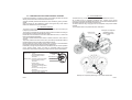
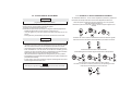
Alarme type:
...........................................................................
Sold on:
...........................................................................
By:
Installed on bike
model, number
plate/frame:
Homologation number:
e24
7853
0079
Homologation label on the control unit body.
ALARM SYSTEMS
7853
e24 0079
WS
USER MANUAL
Made in Italy - For all EU
UK
GEMINI Technologies S.p.A.
Via Luigi Galvani 12 - 21020 Bodio Lomnago (VA) - Italia
Tel. +39 0332 943211 - Fax +39 0332 948080
Web site: www.gemini-alarm.com
NOTE: please send a copy to the insurance company if secessay.
For all EU Countries
AC 2676EU-REV.01- 25/05/07
UK
1.0 - CONTENTS
1.0 - CONTENTS.
2.0 - INTRODUCTION.
3.0 - ALARM CONTROL DEVICES DESCRIPTION.
3.1 - Remote control.
3.2 - Electronic key.
4.0 - ALARM OPERATION WITH BASIC CONFIGURATION.
4.1 - Arming.
4.2 - Trunk open or seat lifted-up signalling.
4.3 - Neutral time.
4.4 - Siren exclusion.
4.5 - Shock sensor exclusion.
4.6 - Armed condition.
4.7 - Alarm.
4.8 - Limiting the acoustic signal.
4.9 - Neutral time between two alarm signals.
4.10 - Alarm system disarming without alarm memory.
4.11 - Alarm system disarming with alarm memory.
5.0 - EXTRA FUNCTIONS DESCRIPTION.
5.1 - Acoustic and optic signalling.
5.2 - Remote controlled panic alarm.
5.3 - Shock sensor.
5.4 - Passive arming.
5.5 - Anti-hijacking function.
5.6 - Pre-alarm.
5.7 - Anti-distraction.
6.0 - SHOCK SENSOR ADJUSTMENT.
7.0 - EXAMPLE OF SHOCK SENSOR ADJUSTMENT.
8.0 - UNLOCK PROCEDURE BY PIN-CODE.
9.0 - EXAMPLE OF SYSTEM UNLOCK BY PIN-CODE.
10.0 - EXAMPLE OF PIN-CODE PERSONALIZATION.
11.0 - SLEEP MODE ACTIVATION/DEACTIVATION.
12.0 - HAZARD SIGNALLING.
13.0 - REMOTE CONTROL BATTERIES REPLACEMENT.
14.0 - USE AND MAINTENANCE.
15.0 - PRODUCT DISPOSAL.
16.0 - WARRANTY CONDITION.
--.- - CONFORMITY.
2.0 - INTRODUCTION
Dear Customer,
Thank you for having chosen a Gemini alarm.
This manual has been written for you so that you can acquaint yourself with
and get the best operation results with your motorbike alarm.
We recommend you to read this manual both carefully and entirely here you
will find some important information, advices, and warnings that will assist you
in operating and making the most of your device.
Gemini's alarms, model 7853, are specifically designed for two-wheel vehicle
protection.
We kindly ask you to check the model you own, verifying the function and the
accessories available with your installer.
Thanks to a safety and comfort functionality, you can program the device
according to your actual needs.
Indeed, although equipped with a number of available functions, the device is
programmed and delivered to the final customer in the so-called “basic”
configuration.
Your alarm is also provided with a PIN-CODE. In case of emergency, the alarm
may be switched off by using the vehicle ignition key, without the need of
control modules such as remote controls and electronic keys.
In order to prevent unauthorized alarm deactivation, we strongly recommend
to change the initial code, which is the same in all systems by factory settings.
For this reason too, we also suggest to keep this manual safely for future use.
In order to better understand the importance of the topics discussed in this
manual, some icons will be included.
These are listed below, along with a brief description of their meaning and
importance level.
! WARNING
It shows a real risk of severe damages to the vehicle and to its alarm
system in case these instructions are not complied with.
CAUTION
It shows a real risk of damages to the system or of any operative
malfunctions of the system in case these instructions are not complied
with.
NOTE
It provides for useful information.
We also recommend you to always wear your crash helmet, keep lights on and
observe the speed limit, when riding your motorbike.
Enjoy your reading… and have a nice trip!
PAG.2
PAG.3
3.0 - DESCRIPTION OF ALARM CONTROL DEVICES
3.2 - ELECTRONIC KEY
In order to use the alarm, it needs to receive commands by the user; this can be
done by means of remote controls and electronic keys.
A further possibility to deactivate the alarm, when needed, is given by the PINCODE.
Such procedure can be activated by means of the ignition key of the vehicle
itself and is detailed in the relevant chapter.
The electronic key can be considered a kind of “simplified remote control.”
As a matter of fact, in emergency situations (e.g. a failure in the remote
control), it can activate and deactivate the alarm, or activate and deactivate the
anti-hijacking function (if previously programmed).
To use the electronic key, simply put it on the receptacle, and join the metallic
contacts.
The receptacle also incorporates the alarm state LED.
3.1 - REMOTE CONTROL
The remote control is the main user “interface”; therefore, we recommend you
to acquaint yourself with it.
The remote control buttons activate several functions that differ according to
the operational condition and the alarm program.
Please also note that buttons have been made different in form, in order to be
better recognized and identified.
The alarm activation/deactivation button is dotted, while the siren button is
smooth.
To prevent problems with the remote control, it has been provided with a device
that will signal the charge condition of the batteries inside.
During normal use of the remote control, when you press a command button
the green transmission LED will light up with a steady light.
If the battery charge drops below the level needed to assure correct operation
of the remote control, when you press a command button the green
transmission LED will blink, advising you that it is time to replace the batteries.
Button Nr.1:!Alarm
Signalling
activation/disactivation.
LED
!Anti hijacking function
Push-button Nr.1
activation.
Button Nr.2:!Hazard function activation. Push-button Nr.2
!Anti hijacking function
activation.
!Panic alarm
activation/deactivation.
!Siren control during alarm
conditions.
!Siren control during alarm
activation.
!Shock sensor programming,
activation and regulation.
Electronic key
Example of receptacle
positioning on the
vehicle plastic side
cover.
Electroni key
Example of receptacle positioning on the vehicle dashboard.
PAG.4
PAG.5
4.0 - ALARM OPERATION WITH BASIC CONFIGURATION
4.6 - ARMED CONDITION
4.1 - ARMING
At the end of the neutral time, after about 20 seconds, the alarm goes in the
armed condition and signals this with a blinking led.
From now on, the alarm is ready to signal possible attempts to force the
vehicle.
Pressing the (dotted) button #1 on the remote control or inserting the electronic
key into the receptacle will activate the system.
This action is indicated by one long flashing of the turn signals, two short
acoustic signals and the permanent turning on of the LED.
4.2 - TRUNK OPENED OR LIFTED-UP SEAT SIGNALLING
During alarm activation, should the seat or the trunk be opened, the alarm will
signal the failure by means of a low-tone signal after the alarm arming
signalling.
In any case the alarm will be activated and, at the end of the "neutral time", an
alarm condition will be generated.
4.3 - NEUTRAL TIME
When the activation signals are finished, the alarm goes in standby or neutraltime condition, which is signalled with a steady-light led.
This time duration is about 20 seconds.
The engine immobilization function and the connectors for optional modules
are already active.
4.4 - SIREN EXCLUSION
During the first 4 seconds of neutral time, the alarm siren can be deactivated,
by simply pressing (smooth) button #2 on the remote control (obviously after
Nr. 1 remote control push-button pressure, system arming).
Siren exclusion will be signalled by a short flashing of the turn signals.
NOTE
When the siren is excluded, the alarm signals will be changed;
Indeed only visual signals will be active, i.e. with flashing of the turn
signals, but the engine immobilization function will still work.
The siren sound exclusion is bound to the single arming cycle.
4.5 - SHOCK SENSOR EXCLUSION
During the first 4” of neutral time, it is possible to exclude the built-in shock
sensor functionning.
To do this, you must just put the electronic key into the specific receptacle, after
the alarm system has been activated.
The exclusion is bound to a single arming cycle and will be indicated by a short
flashing of the status led.
PAG.6
4.7 - ALARM
If, during the armed condition, should occur any theft attempt against the
vehicle, the alarm will signal this by activating the high-volume siren, lighting
up the red led with a steady light and causing the direction indicators to flash
repeatedly for about 30 seconds.
The alarm may be activated by different causes (which also depend on the
activated functions) described below:
!Cut-off of the power supply cables.
!Turn on the ignition key (positive under key).
!Shock.
!Seat/trunk opening (if the protection push-button has been installed).
!Panic alarm, by pushing button #2 (smooth) on the remote control.
When the alarm conditions are over, the system will revert to the armed
condition.
During the alarm condition it is still possible to deactivate the siren sound and
the turn signals flashes by pushing button #2 (smooth) on the remote control
(without disarming the alarm).
4.8 - LIMITING THE ACOUSTIC SIGNALS
Alarm conditions caused by shock, displacement, seat/trunk opening or
ignition key will be signalled by the activation of the siren for 7 times for each
cause.
From the eighth alarm condition on, the siren will cease to be active.
This deactivation of the siren is performed because of these simple reasons:
!Observance of the regulations in force in the subject of acoustic emissions
caused by vehicle alarms.
!Power saving, to maximize the vehicle battery.
!It is no use keeping the alarm on if, after 7 acoustic signals, nobody is
coming to check the vehicle.
!Noise pollution reduction, to prevent penalties as per the regulations in
force.
4.9 - NEUTRAL TIME BETWEEN TWO ALARM SIGNALS
Once the alarm cycle is over, the device will ignore any other alarm cause for
five seconds, while keeping the LED steadily on
During the neutral time between alarm signals, it is possible disarming the
system by PIN CODE, like as described in the relative chapter.
PAG.7
4.10 - SYSTEM DISARMING WITHOUT ALARM MEMORY
5.0 - DESCRIPTION OF THE EXTRA FUNCTIONS
Pressing the button #1 (dotted) on the remote control or inserting the electronic
key in the receptacle will deactivate the system.
The alarm system will signal this change of status with the led switched off,
three beeps and three flashes of the direction indicators at the same time.
The table below shows the programmable functions.
The manufacturer supplies the alarm with some of these functions disabled (in
order to achieve a good trade-off between ease and completeness of use),
being the shock sensor regulated at the minimum of the sensibility.
4.11 - SYSTEM DISARMING WITH ALARM MEMORY
If during the armed period attempts have been made to force the vehicle,
during the deactivation stage the alarm will signal the event with two flashes of
the turn signals and, simultaneously, with two low-tone beeps.
The last cause of alarm will be signalled with one or more flashes of the turn
signals and a corresponding number of beeps, according to the type of event.
Shock sensor alarm:
Starting attempt
alarm:
Trunk open or lift-up
seat alarm:
Factory setting
Function
Acoustic signals
Panic alarm
Shock sensor
Passive arming
Anti-hijacking procedure
Pre-alarm
Anti-distraction
Status
Enabled
Enabled
Enabled
Disabled
Disabled
Disabled
Disabled
5.1 - ACOUSTIC AND OPTIC SIGNALLING
In the different usage conditions, the alarm signals the current operation or the
alarm memory.
This is done using the turn signals an the LED for the optical signals and using
the siren for the acoustic signals (the last one can be disabled).
FUNCTIONNING
During the stages of activation, deactivation, alarm memory, function
programming and learning of new devices, the alarm will produce specific
acoustic and optic signals in order to show which function is being run.
Optic signallings concern either LED or turn signals
The acoustic signals can be high-tone or low-tone.
5.2 - REMOTE CONTROLLED PANIC ALARM
Cut wires alarm:
PAG.8
It allows to generate an alarm condition by pressing button #2 (smooth) on the
remote control.
The panic signals can be as many as desired, but a minimum 5-second interval
must occur between two consecutive signals.
FUNCTIONNING
Pressing button #2 on the remote control will activate the siren and the
direction indicators for about 30 seconds.
To deactivate the panic alarm, just press again button #2 on the remote control.
This alarm signalling can be activated indifferently of the system status
(activated/deactivated).
PAG.9
5.3 - SHOCK SENSOR
The system may generate an alarm condition caused by a shock or a shifting of
the vehicle itself. The shock sensor is buil in the alarm and is adjustable.
FUNCTIONNING
In armed state, if the vehicle is hit or shifted, the sensor included in the alarm
system will detect this anomaly and generate an alarm.
5.4 - PASSIVE ARMING
This function allows the user to leave the vehicle sure that the alarm protection
arms itself automatically.
FUNCTIONNING
Once the engine is switched off, the system automatically activates the
passive arming.
This will be signalled by two LED flashes and two siren high-tone beeps.
After 35 seconds the system will activate steadly, signalling the operation with
a single flash of the turn signals, two acoustic signal and the lighting up of the
LED (with a steady light).
The procedure can be interrupted, by turning on the ignition switch within 35”.
If the trunk is open, the passive arming time will be interrupted, until the trunk
closing.
5.5 - ANTI-HIJACKING FUNCTION
This function ensures some sort of protection against criminals when a theft
attempt happens while the vehicle is in use.
The function indeed allows to activate the system while stopping the vehicle
with the ignition key switch on and the engine running.
FUNCTIONNING
With the ignition key switch on, it is possible to activate the anti-hijacking
function in the following ways:
!By pressing button #1 on the remote control.
!By pressing button #2 on the remote control.
!By inserting the electronic key in the receptacle.
20 seconds after the engine starting up, the alarm will immobilize the vehicle's
engine; two seconds later the siren will be activated at high volume, and the
direction indicators will start blinking repeatedly.
This signalling will continue for a minute and, after this time, the siren will be
deactivated; the turn signals will continue blinking until the anti-hijacking
function is disabled.
To deativate the function insert the electronic key in the receptacle.
5.6 - PRE-ALARM
In alarm condition, this implies the activation of the siren for just 2,5 seconds
(first 3 alarm cause only) rather than the standard 30 seconds.
This considerably reduces power consumption while preserving the vehicle's
battery, and it reduces the environmental acoustic pollution.
FUNCTIONNING
When the alarm is activated, providing an alarm condition is generated (i.e. the
vehicle is accidentally hit), the siren will be activated for about 2,5 seconds.
This condition of pre-alarm will be activated for the first 3 alarm causes.
Indeed, from the fourth cause on, the siren will be activated for about 30
seconds.
The alarm cycles will be reset every time the alarm is deactivated or when the
panic alarm is activated.
5.7 - ANTI-DISTRACTION
This function protects the vehicle in case the alarm would be unintentionally
deactivated.
FUNCTIONNING
The alarm is activated by the user, then unintentionally deactivated by the
same user (e.g. the relevant button on the remote control is pressed).
The user, unconscious about this, will leave the vehicle unprotected, although
being sure of the contrary.
35 seconds after this unintentional deactivation, the alarm will automatically
reactivate, signalling this with the standard acoustic and optical signals.
NOTE
The activation of the anti-hijacking function will be signalled
by the system with two rapid flashes of the
turn signals and a steady LED.
Once enabled the anti-hijacking function, the remote controls won't work
anymore.
PAG.10
PAG.11
6.0 - SHOCK SENSOR ADJUSTMENT
CAUTION
Verify that the shock sensor has not been disabled during the
programmation step by the installer.
The system has a built-in shock sensor, whose sensibility can be adjusted into
5 levels: from the 1st, the lowest to the fifth the highest.
The system is supplied with the lowest one.
Please follow the procedure here below to change the sensibility adjustment:
!Disable the alarm with a remote control or an electronic key.
!Turn the ignition key into “ON” position; the status LED stays on for one
second.
!During this time, push the button Nr.2 of the remote twice in to seconds.
CAUTION
If such a button is pushed the second time after 2 seconds, the procedure
will be stopped.
!The alarm will confirm with two LED flashes and the two acoustic signals
with acute tone that the shock sensor adjustment procedure is entered.
!At the beginning the sensibility of the alarm is adjusted into minimum level.
!Push the button No. 2 of the remote to increase the sensibility (4 times
maximum to reach the highest level); a LED flashing and a short acoustic
signal with acute tone occur, each time the button is pushed.
!As soon as the sensor is adjusted, turn the ignition key to “OFF” position.
!If the adjustment corresponds to the highest level, the system will leave the
procedure automatically.
!In both cases, when the procedure is stopped, a flashing LED and a short
acoustic signal with acute tone occur.
NOTE
Entering the programming procedure resets the functions to Gemini
default setting.
7.0 - EXAMPLE OF SHOCK SENSOR ADJUSTMENT
To understand better the shock sensor adjustment procedure, please find
here below an example where the sensor will be adjusted into third level:
While the system is disarmed, turn the ignition key into “ON” position.
The LED will light for about 1”.
Meanwhile, push the button No. 2 of the remote and push it again in two
seconds.
The alarm will confirm with two LED flashes and the two acoustic signals
with acute tone that the shock sensor adjustment procedure is entered.
Push twice the button Nr.2 of the transmitter.
A LED flashing and an acoustic signal correspond to each pressure.
Turn the ignition key of the vehicle in “OFF” position.
The alarm confirm the end of the procedure by an optical signal of the
LED and an acoustic signal of the control unit.
8.0 - UNLOCK PROCEDURE BY PIN-CODE
9.0 - EXAMPLE OF ALARM SYSTEM UNLOCK BY PIN-CODE
The PIN-CODE procedure allows deactivating the alarm system in case of
emergency, that is to say when, for any reason whatsoever, the remote control
or the electronic key cannot be used.
To have the system deactivated, the final user shall “communicate” a four-digit
numeric code to the system, originally set up by the manufacturer as 1-1-1-1.
Due to obvious safety reasons, we recommend to replace this original code
with another user's customized code.
Please see next pages to carry out this operation, than read the instructions
below to unlock the alarm with the PIN-CODE.
!Cause an alarm situation; as soon as the alarm condition is finished, the
installed LED will turn on and stay fixed for about 5''.
!While the led is on with a fixed light, connect and disconnect the ignition
key switch.
To better understand the alarm system unlock by means of PIN-CODE, please
refer to the following example considering the case of a PIN-CODE formed by
these digits: 2-3-4-1.
NOTE
If, during this phase, the ignition key switch is kept connected for more
than 5'', the system will read this as a theft attempt, so causing another
alarm condition.
!The installed LED will turn off so showing the beginning of the unlock
procedure.
!After 4'' from the LED turning off, it will start flashing for 9 blinks
!As soon as the number of blinks is equal to the first digit of the PIN
CODE, connect and disconnect the ignition key switch, so confirming the
first digit of the code.
!After another 4'', this LED will start flashing for 9 blinks again.
!As soon as the number of blinks is equal to the second digit of the PINCODE, connect and disconnect the ignition key switch, so confirming the
second digit of the code.
!Repeat the same as above for the remaining two digits to be entered.
!As soon as the last digit is stored, the system will be deactivated by
signalling this operation as shown in the paragraph ”system deactivation by
means of alarm memory” riported on the “User Manual”.
NOTE
In case the LED blinks exceeds the number of 9, this procedure will fail
and this will be read as a theft attempt, along with the usual
optical/acoustic signals.
PAG.12
After the system is armed, wait for the end of “neutral time” and then cause
an alarm condition.
Key in
“ON” position.
An alarm condition
will occur.
Key in “OFF”
position.
As soon as the alarm condition is finished, the installed led will turn on and
stay fixed for about 5''.
While the led is on, connect and disconnect the ignition key, the LED will turn
off showing the beginning of the unlock procedure by means of PIN-CODE.
Led fixed
on for
about 5”.
Key in
“OFF”
position.
Key in “ON”
position.
LED turned off.
Unlock
procedure starts
After 4'' from the led turning off, it will start blinking.
As soon as the number of blinks is equal to the first digit of the PIN-CODE
(which is 2 in this case), connect and disconnect the ignition key switch.
After another 4'', this LED will start blinking again.
As soon as the number of blinks is equal to the second digit of the PINCODE (which is 3, in this case), connect and disconnect the gnition key
switch.
4 Sec.
4 Sec.
1st. number: “2” “ON” “OFF”
2nd. number: “3”
“ON” “OFF”
After 4 seconds, the system restarts counting to set up the other following
two digits (which are 4 and 1 in this case).
4 Sec.
4 Sec.
3rd. number: “4”
“ON” “OFF” 4th. number: “1” “ON” “OFF”
As soon as the fourth digit of the PIN-CODE is entered, the alarm system
will be deactivated by showing the last alarm cause.
PAG.13
10.0 - EXAMPLE OF PIN-CODE PERSONALIZATION
To better understand how to set up the PIN-CODE, please refer to the example
below.
The following customized PIN-Code 2-3-4-1 will be entered.
Push both remote control buttons at the same time.
The LED will go off.
LED
off
Turn off the system.
Connect the BROWN/GREEN
wire to ground.
Turn the ignition key in “OFF” position.
Open the saddle of the vehicle if the
safety button is fitted.
Key in “OFF” position.
BROWN/GREEN
NEGATIVE
After four seconds have passed, the LED will begin a series of nine flashes.
Turn the ignition key in “ON” when we intends to memorize the first
figure of the new PIN-CODE.
Turn the ignition key in “ON” position.
Key in “ON”
position.
Key in “ON” position.
The LED installed on the vehicle will light up for 0.5 seconds.
During this time period, press both buttons on the remote control.
The alarm will emit two acoustic signals and then it will light the LED.
Boop
Boop
0.5
Sec.
Remove from negative the
BROWN/GREEN wire.
Afte four seconds have passed, the LED will begin a new series of nine
flashes.
Repeat the operations described above to insert the second number.
Fixed
light
Close the saddle of the vehicle if the
safety button is fitted.
LED
off
Key in “OFF”
position.
Key in “ON”
position.
LED
off
Key in “OFF”
position.
Repeat the same operations described above to insert the other two numbers.
When you have finished inserting the fourth number of the pin-code, the
system will automatically exit the procedure. It will confirm the successful
termination with two low tone acoustic signals and one high tone signal.
BROWN/GREEN
Last
number.
Key in
“ON”
position.
Key in
“OFF”
position.
Boop
Boop
NEGATIVE
PAG.14
PAG.15
11.0 - SLEEP MODE ACTIVATION/DE-ACTIVATION
13.0 - REMOTE CONTROL BATTERIES REPLACEMENT
When the vehicle is not used, it is possible to switch completely off the alarm
(sleep mode) in order to reduce the battery charge consumption.
To activate this function, proceed as follows:
!Turn the ignition key to “ON” position; the LED will light for about one
second.
!After the LED flash put the electronic key into the receptable, within 4
seconds.
!An acoustic signal will indicate that the system is turned off.
!Turn the ignition key of the vehicle to “OFF” position.
!To re-activate the alarm, turn the ignition key of the vehicle to “ON” and
“OFF”.
The remote control operates using alkaline batteries.
Under normal use conditions of the remote control these will gradually lose
their charge.
The more you use the remote control, the sooner the batteries will become
discharged.
To prevent problems with the remote control, it has been provided with a device
that will signal the charge condition of the batteries inside.
During normal use of the remote control, when you press a command button
the green transmission LED will light up with a steady light.
If the battery charge drops below the level needed to assure correct operation
of the remote control, when you press a command button the green
transmission LED will blink, advising you that it is time to replace the batteries.
For battery replacement follow the indications reported below:
!Separate the plastic shells of the remote control, paying attention to not
damage the internal circuit.
!Remove the discharged batteries.
!Insert the new batteries in their housing, being careful to not invert the
polarity.
!Close the plastic shells of the remote.
!Verify the efficiency of the remote control.
12.0 - HAZARD SIGNALLING
The hazard signalling is useful when you want to park the vehicle, being the
vehicle engine off and the turn signals on.
To activate/deactivate this function, proceed as follows:
!Switch off the engine, by turning the ignition key of the vehicle to “OFF”.
!Turn the ignition key to “ON”; the LED will be illuminated for about 1”.
!During this period, push the button Nr.1 of the remote control.
!Turn the ignition key to “OFF”; the turn signals will start flashing.
!To deactivate the function, you must just turn again the ignition key to “ON”
(and eventually to “OFF”), or arm and disarm the system by a remote or by
an electronic key.
BATTERIES
! ATTENTION
Use only batteries CR1616 type.
Using batteries different from those advised can seriously damage the
remote control unit.
Do not discard used batteries in the environment; they should be disposed
in appropriate containers.
PAG.16
PAG.17
14.0 - USE AND MAINTENANCE
16.0 - WARRANTY CONDITIONS
Please note that the alarm system is still an electronic device, so must be
handled carefully.
The following are simple hints which are useful if you want to prevent device
damage because of an improper use.
!Do not clean the control unit with water.
!Do not use power supply voltages which are different than those specified
by the factory .
!If the motorbike is cleaned with a washing machine, be careful not to
directly expose the alarm to the water jets.
This apparatus is guaranteed against all defects of fabrication for a period of 24
months from the installation date shown on the warranty coupon below, taking
into consideration the 1999/44/CE.
Please fill in the warranty certificate contained in this instruction booklet in all
its parts and DO NOT REMOVE the warranty label on the apparatus.
If the warranty label is lost or damaged or if the data on the warranty certificate
is not complete or if the attached sale document is missing, the will not
recognize this warranty.
The warranty is valid exclusively at centers authorized by Gemini
Technologies S.p.A.
The manufacturer declines all responsibility for any defects or malfunctions of
the alarm and of the vehicle electric system if the apparatus is installed
incorrectly, mishandled or improperly used.
The alarm has only a dissuasive function against thefts.
NOTE: Any type of modification or addition not expressly indicated on
the installator manual or authorized by Gemini Technologies S.p.A., will
invalidate automatically the installation certificate and product warranty.
! ATTENTION
Gemini Technologies S.p.A. is not responsible for damages to the system
in case of an improper use of it.
15.0 - PRODUCT DISPOSAL
We remind you that according to the L.D. 151, 25th July 2005,
“IMPLEMENTATION OF E.U.” DIRECTIVES 2002/95, 2002/96 and 2003/108,
concerning the reduction of hazardous substances used in electrical and
electronic devices and the waste disposal, consumer has to:
!Dispose this product separately from urban wastes.
!Collect separately internal components, in specialized centers, since they
are electric and electronic wastes (according to WEEE).
Wrong disposal of electric and electronic devices can cause soil and water
pollution, with consequences for human health.
When the consumer has the intention to replace the product and so he must
dispose it, there is the possibility to give it back to the dealer, in case the device
is of an equivalent type, with similar functions.
In case of abusive disposal of the above wastes, producer, distributor and
consumer will be punished with administrative sanctions, according to the art.
50, L.D. 22/1997.
!
SUITABLE
CONTAINER ONLY
PAG. I
PAG. II
Declaration of conformity to type
Dichiarazione di conformità
I hereby declare that the product
Qui di seguito si dichiara che il prodotto
7208E - 7218E
(Name of product, type or model, batch or serial number)
(nome del prodotto o modello, categoria o numero di serie)
Is conform to all relevant essential requirements of the R&TTE-directive
1995/5/EC, issued March 9,1999. According to Annex IV of the R&TTE
directive. The following standards and essential radio test suites published in
the “Official Journal” of the European Communities, have been used to
demonstrate the conformity of the product:
Product in class 1 frequency identification - subclass 20
En 60950-2000
Electrical safety:
En 300220-3/2000
Radio and spectrum engineering parameters:
ETS 301489-3
Electromagnetic Compatibility EMC:
Soddisfa tutti i requisiti applicabili alla tipologia del prodotto e richiesti dalla
regolamentazione delle telecomunicazioni secondo direttiva R&TTE5/9
allegato IV tramite l’utilizzo delle norme pubblicate nella gazzetta ufficiale della
Comunità Europea:
Prodotto in frequenza identificata come classe 1 - sottoclasse 20
Sicurezza elettrica:
En 60950-2000
Radio e parametri di trasmissione:
En 300220-3 /2000
Compatibilità elettromagnetica EMC:
ETS301489-3
The product can be used in the following European Countries: A, B, D, DK, F,
Il prodotto può essere immesso nei seguenti Stati Europei: FR, GR, IR, I, L,
NL, P, SP, S, UK
GEMINI
Company responsible for placing on the market:
Società responsabile per l’immissione nel mercato: TECHNOLOGIES S.p.A.
Address:
Indirizzo:
Point of contact:
Persona di contatto:
Via Luigi Galvani 12 - 21020 BODIO LOMNAGO
(VA) - ITALY
Bodio Lomnago - 19/09/2003
(Place, date) - (Luogo, data)
Andrea Rossi
(Signature) - (Firma)