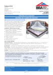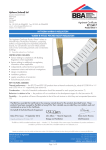
1
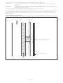
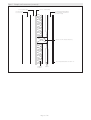
APPROVAL
INSPECTION
TESTING
CERTIFICATION
International Petroleum Products Ltd
Bradwell Hall
Bradwell on Sea
Essex CM0 7HX
Tel: 01621 776252 Fax: 01621 776688
TECHNICAL APPROVALS FOR CONSTRUCTION
Agrément Certificate
10/4789
e-mail: [email protected]
website: www.intpetro.com
Product Sheet 2
ALUMAFLEX MULTIFOIL INSULATION
ALUMAFLEX MULTILAYER INSULATION FOR TIMBER FRAME AND MASONRY WALL APPLICATIONS
PRODUCT SCOPE AND SUMMARY OF CERTIFICATE
This Certificate relates to Alumaflex Multilayer Insulation
for Timber Frame and Masonry Wall Applications, a
reflective insulation material for use on the inner side
(warm side) of the timber frame or masonry substrate
and held in place by timber battens creating airspace
between the product and the internal lining in domestic
and non-domestic buildings.
AGRÉMENT CERTIFICATION INCLUDES:
• factors relating to compliance with Building
Regulations where applicable
• factors relating to additional non-regulatory
information where applicable
• independently verified technical specification
• assessment criteria and technical investigations
• design considerations
• installation guidance
• regular surveillance of production
• formal three-yearly review.
KEY FACTORS ASSESSED
Thermal performance — when combined with other types of insulation, the product can contribute to meeting the
U value requirement for a wall (see section 5).
Condensation risk — the product will contribute to minimising the risk of interstitial and surface condensation. It
has a water vapour resistance in excess of 1200 MN·s·g–1 and may be used as a vapour control layer (see section 6).
Behaviour in relation to fire — the product does not prejudice the fire resistance properties of the wall (see section 8).
Durability — the durability of the product is satisfactory and will have a life equivalent to the structure in which it is
incorporated (see section 12).
The BBA has awarded this Agrément Certificate to the company named above for the product described
herein. The product has been assessed by the BBA as being fit for its intended use provided it is installed, used
and maintained as set out in this Certificate.
On behalf of the British Board of Agrément
Date of First issue: 10 December 2010
Simon Wroe
Head of Approvals — Physics
Greg Cooper
Chief Executive
The BBA is a UKAS accredited certification body — Number 113. The schedule of the current scope of accreditation for product certification is
available in pdf format via the UKAS link on the BBA website at www.bbacerts.co.uk
Readers are advised to check the validity and latest issue number of this Agrément Certificate by either referring to the BBA website or contacting the BBA direct.
British Board of Agrément
Bucknalls Lane
Garston, Watford
Herts WD25 9BA
©2010
Page 1 of 12
tel: 01923 665300
fax: 01923 665301
e-mail: [email protected]
website: www.bbacerts.co.uk
Regulations
In the opinion of the BBA, Alumaflex Multilayer Insulation for Timber Frame and Masonry Wall Applications, if used
in accordance with the provisions of this Certificate, will meet or contribute to meeting the relevant requirements of
the following Building Regulations:
The Building Regulations 2010 (England and Wales)
Requirement: C2(c)
Resistance to moisture
Comment:
The product will contribute to minimising the risk of surface and interstitial condensation. See sections 6.1
and 6.6 of this Certificate.
Requirement: L1(a)(i)
Conservation of fuel and power
Comment:
Requirement: Regulation 7
Materials and workmanship
Comment:
The product is acceptable. See section 12 and the Installation part of this Certificate.
The product can contribute to meeting this Requirement. See sections 5.3 and 5.4 of this Certificate.
The Building (Scotland) Regulations 2004 (as amended)
Regulation:
8(1)
The product satisfies the requirements of this Regulation. See section 12 and the Installation part of this
Certificate.
Comment:
Regulation:
Standard:
9
3.15
6.1(b)
6.2
Carbon dioxide emissions
Building insulation envelope
The product can contribute to a wall satisfying the requirements of this Standard, with reference to clauses
6.1.1(1), 6.1.2(2), 6.1.3(1), 6.1.6(1), 6.2.1(1)(2), 6.2.4(1)(2), 6.2.5(1)(2), 6.2.6(1)(2), 6.2.8(1)(2), 6.2.9(1)(2),
6.2.11(1)(2), 6.2.12(1)(2) and 6.2.13(1)(2) of these Standards. See sections 5.3 and 5.4 of this Certificate.
Comment:
Regulation:
Building standards — construction
Condensation
The product can contribute to satisfying this Standard, with reference to clauses 3.15.1(1)(2), 3.15.4(1)(2),
3.15.5(1)(2). See sections 6.1 and 6.7 of this Certificate.
Comment:
Standard:
Standard:
Fitness and durability of materials and workmanship
12
Building standards — conversions
All comments given for this product under Regulation 9, also apply to this Regulation, with reference to
clause 0.12.1(1) and Schedule 6(1).
Comment:
(1) Technical Handbook (Domestic).
(2) Technical Handbook (Non-Domestic).
The Building Regulations (Northern Ireland) 2000 (as amended)
Regulation:
B2
Fitness of materials and workmanship
Comment:
Regulation:
C5
Condensation
The product is acceptable. See section 12 and the Installation part of this Certificate.
The product will contribute to minimising the risk of interstitial condensation. See section 6.1 of this
Certificate.
Comment:
Regulation:
Regulation
Comment:
F2(a)(i)
F3(2)
Conservation measures
Target carbon dioxide Emissions Rate
The product can contribute to satisfying these Regulations. See sections 5.3 and 5.4 of this Certificate.
Construction (Design and Management) Regulations 2007
Construction (Design and Management) Regulations (Northern Ireland) 2007
In the opinion of the BBA, there is no information in this Certificate which relates to the obligations of the client, CDM
co-ordinator, designer or contractors under these regulations.
Non-regulatory Information
NHBC Standards 2010
NHBC accepts the use of Alumaflex Multilayer Insulation for Timber frame and Masonry Wall Applications, when
installed and used in accordance with this Certificate, in relation to NHBC Standards, Chapter 6.1 External masonry
walls and Chapter 6.2 External timber framed walls.
Page 2 of 12
Technical Specification
1 Description
1.1 Alumaflex Multilayer Insulation for Timber Frame and Masonry Wall Applications is an insulation material
comprising 14 layers, where the outer layer is a PET (polyethylene terephthalate) fused to a PE (polyethylene) bubble
layer which is then fused to a non woven polypropylene backing. The core of the product consists of wadding,
reflective foil and PE foam layers.
1.2 The product is available in rolls of 10 m in length, 1.2 m and 1.5 m in width and 30 mm thick.
1.3 Ancillary items(1) used with the product are:
• Alumaflex aluminium tape
• timber battens
• plasterboard to BS EN 520 : 2004
• screws
• nails or staples minimum 14 mm length
• additional insulation.
(1) Outside the scope of this Certificate.
2 Delivery and site handling
2.1 The product is delivered to site in rolls packed in a protective, branded bag, sealed with an end label.
2.2 The rolls should be stored in clean, dry conditions not exposed to sunlight. The product must be protected from
being dropped or crushed by objects. Care must be exercised when storing large quantities on site. The product must
not be exposed to open flame or other ignition sources and must be stored away from flammable material such as
paint and solvents.
2.3 On site, to ensure maximum performance of the product when installed, precautions must be taken to protect it
from mud and dirt.
Assessment and Technical Investigations
The following is a summary of the assessment and technical investigations carried out on Alumaflex Multilayer Insulation
for Timber Frame and Masonry Wall Applications.
Design Considerations
3 General
3.1 Alumaflex Multilayer Insulation for Timber Frame and Masonry Wall Applications will improve the thermal
insulation of walls of dwellings and non dwellings.
3.2 The wall or sub-frame should be structurally sound and should have been designed and constructed in accordance
with the following standards:
• timber — BS EN 1995-1-1 : 2004+A1 : 2008, BS 5589 : 1989 and BS EN 351-1 : 1996.
• masonry — BS EN 1996-1-1 : 2005, BS EN 5628-3 : 2005, BS 8110-1 : 1997, BS 8110-2 : 1985,
BS EN 1996-2 : 2006.
3.3 The installation requires careful detailing around doors and windows to achieve a satisfactory surface for finishing.
In addition, every attempt should be made to minimise the risk of thermal bridging at reveals and where heavy
separating walls are attached to the external wall. In new work, the construction must be designed to accommodate
the thickness of the dry lining, particularly at reveals, heads and sills.
3.4 Services can be incorporated behind the dry lining, making chasing of the wall unnecessary. Where possible,
penetration of the product by services should be kept to a minimum to limit possible penetration by water vapour.
3.5 Installation of plasterboard must be in accordance with the relevant sections of BS 8212 : 1995.
4 Practicability of installation
The product can be installed by a competent general builder, or a contractor, experienced with this type of product.
5 Thermal performance
5.1 Calculations of thermal transmittance (U value) should be carried out in accordance with BS EN ISO 6946 :
2007 and BRE Report (BR 443 : 2006) Conventions for U-value calculations using the following values:
• 0.90 m2·K·W–1
R value for Alumaflex
• 0.05
outer surface emissivity
(1)
2
–1
• 0.66 m ·K·W
R value of an air cavity adjacent to the product ⭓20 mm thick (horizontal heat flow)
Page 3 of 12
• 0.00 m2·K·W–1
• 50%/50%
• 0%/100%
R(2) value of product when compressed between battens and studs
percentage of multi-foil thickness in stud and plasterboard-batten cavities, respectively, in wall
applications
percentage of multi-foil thickness in stud and plasterboard-batten cavities, respectively, when stud
depth is fully filled with insulation.
(1) Unventilated cavity with a width and length at least 10 times the thickness and one high emissivity surface.
(2) For guidance on U value calculations refer to the BBA Information Bulletin No 3 Reflective foil insulation — Conventions for U value calculations.
5.2 The U value of a completed wall will depend on the thickness and conductivity of the additional insulation used
and the extent and arrangement of timber bridging. Example wall constructions are shown in Figure 1 and resulting
U values in Table 1.
Figure 1 Example wall constructions
(a) Brick Wall Construction
⫺1
⫺1
215 mm brick at 0.77 W·m K
Multifoil insulation
47 mm x 47 mm horizontal plasterboard
battens at 600 mm centres [net area (11.8%)]
⫺1
⫺1
12.5 mm plasterboard at 0.25 W·m K
additional
insulation
Page 4 of 12
Figure 1 Example wall constructions (continued)
(b) Timber Frame Wall Construction
50 mm vented cavity
12 mm OSB sheathing
horizontal plasterboard batten
47 mm wide by 38 mm thick
(net area 11.8%)
100 mm brick at
0.77 W·m⫺1K⫺1
89 mm x 50 mm studs (net area15%)
12.5 mm plasterboard at 0.25 W·m⫺1K⫺1
additional
insulation
Multifoil
Page 5 of 12
Table 1 U values for specific constructions
Construction
Studs depth
Additional insulation thickness(1)
U value
(W·m–2·K–2)
Masonry wall
Figure 1(a)
–
–
–
–
40 mm EPS
30 mm PUR
95 mm EPS
65 mm PUR
0.28
0.28
0.19
0.19
89
89
140
50 mm EPS
35 mm PUR
90 mm PUR
0.28
0.28
0.19
Timber frame wall
Figure 1(b)
(1) MW insulation (conductivity 0.04 W1·m–1·K–1), PUR Insulation (conductivity 0.022 W·m–1·K–1) and emissivity 0.2,
and EPS (conductivity 0.032 W1·m–1·K–1) thickness rounded to nearest 5 mm.
5.3 Mean design U values are shown in Tables 2 to 4.
Table 2 Mean design wall U values — England and Wales (1)
Construction
U value
W·m–2·K–1
Notional non-domestic building
0.26
Existing building – new and replaced wall
0.28
Dwelling new-build limit
0.30
Notional dwelling
0.35
Non-domestic new-build limit
0.35
Existing building – renovated or retained wall
0.30
(1) Flexible approaches on existing buildings are given in the Approved Documents.
Table 3 Mean design wall U values — Scotland (1)
Construction
U value
W·m–2·K–1
Notional dwelling
0.19
New dwelling simplified method
0.19
Conversion unheated building (into dwellings)
0.19
Extension to dwelling
0.19
Alterations and reconstructions to a dwelling
0.19
Stand alone building < 50 m to a dwelling
0.19
2
New non-dwellings limit for shell and fit out
0.23
New dwelling limit
0.25
Conversion of unheated building
0.25
Non-domestic extension, alterations and reconstructions
0.25
New non-domestic limit
0.27
Conversion of heated building (into dwellings)
0.30
Notional non-dwelling
0.30
(1) Flexible approaches on existing buildings are given in the Technical Handbooks.
Table 4 Mean design wall U values — Northern Ireland (1)
Element
U value
W·m–2·K–1
Existing building – new wall
0.30
Notional dwelling
0.35
Notional non-domestic building
0.35
Building new-build limit
0.35
Existing building – replaced wall
0.35
Existing building – renovated and retained wall
0.35
(1) Flexible approaches on existing buildings are given in the Technical Booklets.
Page 6 of 12
5.4 The product can contribute to maintaining continuity of thermal insulation at junctions between elements. For
Accredited Construction Details the corresponding psi values in BRE Information Paper IP1/06 Assessing the effects of
thermal bridging at junctions and around openings, Table 3 may be used in carbon emission calculations in Scotland
and Northern Ireland. Detailed guidance for other junctions and on limiting heat loss by air infiltration can be found in:
England and Wales — Approved Documents to Part L and for new thermal elements to existing buildings, Accredited
Construction Details (version 1.0). See also SAP 2009 Appendix K and the iSBEM User Manual for new-build.
Scotland — Accredited Construction Details (Scotland).
Northern Ireland — Accredited Construction Details (version 1.0).
6 Condensation risk
Interstitial Condensation
6.1 Walls incorporating the product will contribute to limiting the risk of interstitial condensation when designed
and constructed in accordance with BS 5250 : 2002 (Section 8.3 and Annex D).
6.2 The product has a high water vapour resistance in excess of 1200 MN·s·g–1 and will, therefore, provide
significant resistance to the passage of water vapour and would be considered a vapour control layer as defined in
BS 5250 : 2002 provided all laps and joints are sealed.
6.3 The use of the product does not preclude the normal precautions against formation of condensation, especially in
rooms expected to have high humidity.
6.4 When using this type of product, due consideration must be taken of the overall installation to minimise
perforations by services, eg light switches and power outlets and the joints at ceiling and skirting level must be well
sealed.
6.5 As with any other insulation applied to the inside of a wall, there may be risk of thermal bridging from the floor
or ceiling, particularly in concrete slab construction. It has been demonstrated that the use of coving at the wall ceiling
point will significantly reduce the problem.
Surface Condensation
6.6 Walls incorporating the product will contribute to limiting the risk of surface condensation adequately when
the thermal transmittance (U value) does not exceed 0.7 W·m–2·K–1 at any point, and the junctions with other
elements are designed in accordance with the relevant requirements of Limiting thermal bridging and air leakage :
Robust construction details for dwellings and similar buildings TSO 2002 or BRE Information Paper IP 1/06.
6.7 Walls will adequately limit the risk of surface condensation when the thermal transmittance (U value) does
not exceed 1.2 W·m–2·K–1 at any point and designed in accordance to BS 5250 : 2002, Section 8. Further
guidance may be obtained from BRE Report (BR 262 : 2002).
7 Infestation
The use of the product does not in itself promote infestation. The creation of voids may provide habitation for insects or
rodents in areas already infested. Care should be taken to ensure that, wherever possible, all voids are sealed as any
infestation may be difficult to eradicate. There is no food value in the materials used.
8 Behaviour in relation to fire
8.1 When installed with an internal lining board, eg 12.5 mm thick plasterboard, the insulation will be contained
between the wall and internal lining board, until one is destroyed. Therefore, the insulation will not contribute to the
development stages of a fire or present a smoke or toxic hazard.
8.2 When installed with other additional insulation materials, the fire properties of these materials must be taken into
consideration.
8.3 Construction elements must incorporate cavity barriers at edges, around openings, at junctions with fire-resisting
elements in accordance with the relevant provisions of the national Building Regulations. The design and installation of
cavity barriers must take into account any anticipated differential movement.
9 De-rating of electrical cables
As with other insulation products, it may be necessary in some cases to de-rate electrical cables buried in insulation.
BS 7671 : 2008 suggests that where wiring is completely surrounded by insulation, it may need to be de-rated to as
low as half its free air current carrying capacity. Guidance should be sought from a qualified electrician.
Page 7 of 12
10 Proximity of flues and appliances
When installing the products in close proximity to certain flue pipes and/or heat-producing appliances, the following
provisions to the national Building Regulations are acceptable:
England and Wales — Approved Document J, Paragraph 2.15
Scotland — Mandatory Standard 3.19, Clause 3.19.1(1)(2) and 3.19.4(1)(2)
(1) Technical Handbook (Domestic).
(2) Technical Handbook (Non-Domestic).
Northern Ireland — Technical Booklet L, Paragraph 2.9.
11 Maintenance
As the product is confined behind the wall lining (see section 12), maintenance is not required.
12 Durability
The product will have a life equivalent to that of the wall structure in which it is incorporated.
Installation
13 General
13.1 Installation of the product and additional insulation products should be in accordance with the Certificate
holder’s instructions and current good building practice.
13.2 Care must be taken to ensure the product is not damaged during installation. Should damage occur by tearing,
the product should be repaired by covering the holes with tape. The product is attached to wall studs using staples or
nails of at least 14 mm length. The product must have overlap joints of at least 100 mm and be taped along the entire
length of the joint with Alumaflex aluminium tape.
13.3 When the product is cut to fit around openings, care should be taken to minimise gaps. The product can be cut
easily using a knife. Any exposed cut edges of the product should be sealed with a suitable adhesive tape.
14 Procedure
Additional insulation
14.1 Care should be taken that all air gaps are maintained in accordance with the Certificate holder’s instructions
for the product. Mineral wool can be placed inside the cavity formed when the product is installed across studs. Rigid
insulation products can be placed inside the cavity. Suitable fixings such as wooden battens nailed to the sides of the
studs can be used to generate an air layer between the rigid insulation and the other components of the wall.
Timber frame wall
14.2 Installation may be either vertical or horizontal runs. If horizontal, installation should start at the floor and go up
to the ceiling.
14.3 The product is unrolled across the inner face of the timber studs and fixed using staples or nails of at least
14 mm length.
14.4 The next layer must overlap the first layer by at least 100 mm and be taped along the entire length of the joint
with Alumaflex aluminium tape. If securely taped, the product can also function as a vapour control layer and air
barrier.
14.5 The product should be permanently fixed in place using wooden battens of size at least 38 mm wide by 38 mm
or 47 mm deep, parallel or perpendicular to the wall studs held in place with nails.
14.6 When the top layer has been battened, any excess material may be removed by running a sharp knife along
the edge of the batten.
14.7 Plasterboard is fixed to the battens in the conventional manner.
Solid masonry wall
14.8 Timber battens at least 38 mm deep by 47 mm wide are screwed to the wall at no greater than 600 mm
vertical centres, at wall perimeters and horizontally as required.
14.9 The product is installed as for timber frame walls with plasterboard battens coinciding with the existing battens.
Page 8 of 12
Technical Investigations
15 Tests
Tests were carried out on Alumaflex Multilayer Insulation for Timber Frame and Masonry Wall Applications to
determine:
• emissivity
• durability of the outer foil
• the thickness
• the resistance of the core material of were tested.
16 Investigations
An assessment was made of data relating to:
• the thermal insulation properties
• condensation risk analysis
• U value calculations.
Page 9 of 12
Bibliography
BS 5250 : 2002 Code of practice for control of condensation in buildings
BS 5589 : 1989 Code of practice for preservation of timber
BS 5628-3 : 2005 Code of practice for the use of masonry — Materials and components, design and workmanship
BS 7671 : 2008 Requirements for electrical installations. IEE Wiring Regulations. Seventeenth Edition
BS 8110-1 : 1997 Structural use of concrete — Code of practice for design and construction
BS 8110-2 : 1985 Structural use of concrete — Code of practice for special circumstances
BS 8212 : 1995 Code of practice for dry lining and partitioning using gypsum plasterboard
BS EN 351-1 : 1996 Durability of wood and wood-based products — Preservative-treated solid wood —
Classification of preservative penetration and retention
BS EN 520 : 2004 Gypsum plasterboards — Definitions, requirements and test methods
BS EN 1995-1-1 : 2004 Eurocode 5 : Design of timber structures — General — Common rules and rules for buildings
NA to BS EN 1995-1-1 : 2004 UK National Annex to Eurocode 5 : Design of timber structures — General —
Common rules and rules for buildings
BS EN 1996-1-1 : 2005 Eurocode 6 : Design of masonry structures — General rules for reinforced and unreinforced
masonry structures
BS EN 1996-2 : 2006 Eurocode 6 : Design of masonry structures — Design considerations, selection of materials and
execution of masonry
BS EN ISO 6946 : 2007 Building components and building elements — Thermal resistance and thermal transmittance
— Calculation method
Page 10 of 12
Conditions of Certification
17 Conditions
17.1 This Certificate:
• relates only to the product/system that is named and described on the front page
• is granted only to the company, firm or person named on the front page — no other company, firm or person may
hold or claim any entitlement to this Certificate
• is valid only within the UK
• has to be read, considered and used as a whole document — it may be misleading and will be incomplete to be selective
• is copyright of the BBA
• is subject to English law.
17.2 Publications and documents referred to in this Certificate are those that the BBA deems to be relevant at the date
of issue or re-issue of this Certificate and include any: Act of Parliament; Statutory Instrument; Directive; Regulation;
British, European or International Standard; Code of Practice; manufacturers’ instructions; or any other publication or
document similar or related to the aforementioned.
17.3 This Certificate will remain valid for an unlimited period provided that the product/system and the manufacture
and/or fabrication including all related and relevant processes thereof:
• are maintained at or above the levels which have been assessed and found to be satisfactory by the BBA
• continue to be checked as and when deemed appropriate by the BBA under arrangements that it will determine
• are reviewed by the BBA as and when it considers appropriate.
17.4 In granting this Certificate, the BBA is not responsible for:
• the presence or absence of any patent, intellectual property or similar rights subsisting in the product/system or any
other product/system
• the right of the Certificate holder to manufacture, supply, install, maintain or market the product/system
• individual installations of the product/system, including the nature, design, methods and workmanship of or related
to the installation
• the actual works in which the product/system is installed, used and maintained, including the nature, design,
methods and workmanship of such works.
17.5 Any information relating to the manufacture, supply, installation, use and maintenance of this product/system
which is contained or referred to in this Certificate is the minimum required to be met when the product/system is
manufactured, supplied, installed, used and maintained. It does not purport in any way to restate the requirements
of the Health & Safety at Work etc Act 1974, or of any other statutory, common law or other duty which may exist
at the date of this Certificate; nor is conformity with such information to be taken as satisfying the requirements of the
1974 Act or of any statutory, common law or other duty of care. In granting this Certificate, the BBA does not accept
responsibility to any person or body for any loss or damage, including personal injury, arising as a direct or indirect
result of the manufacture, supply, installation, use and maintenance of this product/system.
Page 11 of 12
British Board of Agrément
Bucknalls Lane
Garston, Watford
Herts WD25 9BA
©2010
Page 12 of 12
tel: 01923 665300
fax: 01923 665301
e-mail: [email protected]
website: www.bbacerts.co.uk