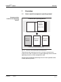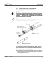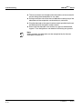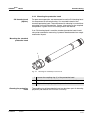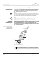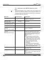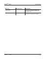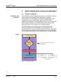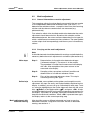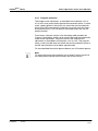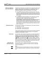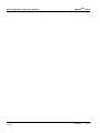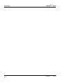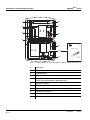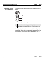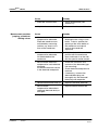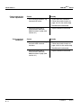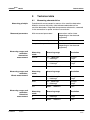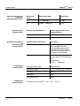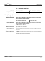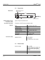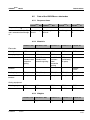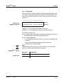
1
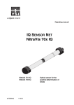
Operating manual IQ SENSOR NET VARiON®Plus 700 IQ IQ SENSOR NET Modular combination sensor for ammonium and nitrate ba76000e01 01/2012 VARiON®Plus 700 IQ Note For the most recent version of the manual, please visit www.ysi.com. Contact Copyright 2 YSI 1725 Brannum Lane Yellow Springs, OH 45387 USA Tel: +1 937-767-7241 800-765-4974 Email: [email protected] Internet: www.ysi.com © 2012 Xylem Inc. ba76000e01 01/2012 VARiON®Plus 700 IQ Contents VARiON®Plus 700 IQ - Contents 1 Overview . . . . . . . . . . . . . . . . . . . . . . . . . . . . . . . . . . . . 1-1 1.1 1.2 1.3 2 Safety instructions . . . . . . . . . . . . . . . . . . . . . . . . . . . . 2-1 2.1 2.2 3 3.4 3.5 4.3 01/2012 Scopes of delivery . . . . . . . . . . . . . . . . . . . . . . . . . . . . . 3-1 IQ SENSOR NET system requirements . . . . . . . . . . . . . . 3-2 Notes on the handling of the electrodes . . . . . . . . . . . . . 3-3 3.3.1 Reference electrode . . . . . . . . . . . . . . . . . . . . . 3-3 3.3.2 Measurement electrodes and compensation electrodes . . . . . . . . . . . . . . . . . . . . . . . . . . . . . 3-4 Preparing the sensor for measurement . . . . . . . . . . . . . 3-5 3.4.1 Equipping the sensor with electrodes . . . . . . . . 3-5 3.4.2 Mounting the protective hood . . . . . . . . . . . . . . 3-7 3.4.3 Connecting the sensor to the IQ SENSOR NET . 3-8 Settings . . . . . . . . . . . . . . . . . . . . . . . . . . . . . . . . . . . . 3-10 3.5.1 General information . . . . . . . . . . . . . . . . . . . . . 3-10 3.5.2 Setting table of the VARiON A (ammonium sensor) . . . . . . . . . . . . . . . . . . . . . . . . . 3-11 3.5.3 Setting table of the VARiON N (nitrate sensor) 3-14 3.5.4 Setting table of the VARiON K (potassium sensor) . . . . . . . . . . . . . . . . . . . . . . . . . 3-16 Matrix adjustment, check and calibration . . . . . . . . . 4-1 4.1 4.2 ba76000e01 Authorized use . . . . . . . . . . . . . . . . . . . . . . . . . . . . . . . . 2-2 General safety instructions . . . . . . . . . . . . . . . . . . . . . . . 2-2 Commissioning . . . . . . . . . . . . . . . . . . . . . . . . . . . . . . 3-1 3.1 3.2 3.3 4 How to use this component operating manual . . . . . . . . 1-1 Structure of the combination sensor VARiON®Plus 700 IQ . . . . . . . . . . . . . . . . . . . . . . 1-2 Recommended fields of application . . . . . . . . . . . . . . . . 1-4 General information . . . . . . . . . . . . . . . . . . . . . . . . . . . . 4-1 Matrix adjustment . . . . . . . . . . . . . . . . . . . . . . . . . . . . . . 4-3 4.2.1 General information on matrix adjustment . . . . 4-3 4.2.2 Carrying out the matrix adjustment . . . . . . . . . . 4-3 4.2.3 Result of the matrix adjustment . . . . . . . . . . . . . 4-5 4.2.4 Program extension . . . . . . . . . . . . . . . . . . . . . . 4-7 Check and calibration in standard solutions . . . . . . . . . . 4-8 4.3.1 General information on checking and calibrating . . . . . . . . . . . . . . . . . . . . . . . . 4-8 0-1 VARiON®Plus 700 IQ Contents 4.3.2 4.3.3 5 Measuring . . . . . . . . . . . . . . . . . . . . . . . . . . . . . . . . . . . 5-1 5.1 5.2 6 Electrodes . . . . . . . . . . . . . . . . . . . . . . . . . . . . . . . . . . . .7-1 General accessories . . . . . . . . . . . . . . . . . . . . . . . . . . . .7-1 What to do if ... . . . . . . . . . . . . . . . . . . . . . . . . . . . . . . . 8-1 8.1 8.2 9 General maintenance notes . . . . . . . . . . . . . . . . . . . . . .6-1 Exterior cleaning . . . . . . . . . . . . . . . . . . . . . . . . . . . . . . .6-3 Exchanging the electrodes . . . . . . . . . . . . . . . . . . . . . . .6-5 Polishing the chloride electrode . . . . . . . . . . . . . . . . . . .6-6 Replacement parts and accessories . . . . . . . . . . . . . 7-1 7.1 7.2 8 Measuring operation . . . . . . . . . . . . . . . . . . . . . . . . . . . .5-1 Factors affecting the measured value . . . . . . . . . . . . . . .5-1 Maintenance and electrode exchange . . . . . . . . . . . . 6-1 6.1 6.2 6.3 6.4 7 Result of the check . . . . . . . . . . . . . . . . . . . . .4-10 Result of the calibration . . . . . . . . . . . . . . . . . .4-11 Interpretation of the drift voltage . . . . . . . . . . . . . . . . . . .8-1 Error causes and remedies . . . . . . . . . . . . . . . . . . . . . . .8-2 Technical data . . . . . . . . . . . . . . . . . . . . . . . . . . . . . . . 9-1 9.1 9.2 9.3 9.4 9.5 Measuring characteristics . . . . . . . . . . . . . . . . . . . . . . . .9-1 Application conditions . . . . . . . . . . . . . . . . . . . . . . . . . . .9-3 General data . . . . . . . . . . . . . . . . . . . . . . . . . . . . . . . . . .9-4 Electrical data . . . . . . . . . . . . . . . . . . . . . . . . . . . . . . . . .9-4 Data of the VARiON®Plus electrodes . . . . . . . . . . . . . . .9-5 9.5.1 Response times . . . . . . . . . . . . . . . . . . . . . . . . .9-5 9.5.2 Materials . . . . . . . . . . . . . . . . . . . . . . . . . . . . . .9-5 9.5.3 Weights . . . . . . . . . . . . . . . . . . . . . . . . . . . . . . .9-5 10 Contact Information . . . . . . . . . . . . . . . . . . . . . . . . . . 10-1 10.1 Ordering & Technical Support . . . . . . . . . . . . . . . . . . .10-1 10.2 Service Information . . . . . . . . . . . . . . . . . . . . . . . . . . . .10-1 11 Indexes . . . . . . . . . . . . . . . . . . . . . . . . . . . . . . . . . . . . 11-1 11.1 Explanation of the messages . . . . . . . . . . . . . . . . . . . .11-1 11.1.1 Error messages . . . . . . . . . . . . . . . . . . . . . . . .11-1 11.1.2 Info messages . . . . . . . . . . . . . . . . . . . . . . . . .11-2 11.2 Status info . . . . . . . . . . . . . . . . . . . . . . . . . . . . . . . . . . .11-3 0-2 ba76000e01 01/2012 VARiON®Plus 700 IQ Overview 1 Overview 1.1 How to use this component operating manual Structure of the IQ SENSOR NEToperating manual IQ Sensor Net Operating Manual System Operating Manual (Ring Binder) IQ Sensor Operating Manual MIQ Module Operating Manual MIQ Terminal Operating Manual Component Operating Manuals Fig. 1-1 Structure of the IQ SENSOR NET operating manual The IQ SENSOR NET operating manual has a modular structure like the IQ SENSOR NET itself. It consists of a system operating manual and the operating manuals of all the components used. Please file this component operating manual in the ring binder of the system operating manual. ba76000e01 01/2012 1-1 VARiON®Plus 700 IQ Overview 1.2 Structure of the combination sensor VARiON®Plus 700 IQ 1 Fig. 1-2 2 3 4 5 ®Plus Structure of the combination sensor VARiON 700 IQ 1 Protective hood 2 Temperature probe 3 Electrode support with electrodes (sample equipment) 4 Sensor shaft 5 Plug head connector Electrodes For a VARiON®Plus 700 IQ combination sensor ready to measure, a jointly used reference electrode and at least one ion sensitive electrode for the main measured parameters (ammonium, nitrate) are required. The electrodes are screwed into the electrode support. The electrode support has four receptacles for this. Automatic interfering ions compensation The VARiON®Plus 700 IQ enables the automatic interfering ions compensation for one main measured parameter. Thus the influence of certain interfering ions due to measuring technique can be automatically compensated for. Interfering ions in water / waste water applications are mostly chloride for nitrate measurement and potassium for ammonium measurement. To determine the interfering ions concentration, another electrode (compensation electrode) is mounted into a free receptacle. Note Information on the fundamentals of measuring with ion sensitive electrodes are given in the YSI primer, ION SELECTIVE MEASUREMENT IN ONLINE ANALYSIS. Operating modes and electrode equipment 1-2 Due to its modular structure, the VARiON®Plus 700 IQ can be adapted to various requirements (see table on the following page). ba76000e01 01/2012 VARiON®Plus 700 IQ Overview Notes: The reference electrode has an extra receptacle marked by a recess. The ion sensitive electrodes can be mounted in the remaining three receptacles in any order. Empty receptacles have to be closed with the VARiON® BP blind plug. Operating mode Ammonium measurement, compensated Electrode equipment VARiON®Plus NH4 VARiON® Ref Ref Blind plug (recess) Nitrate measurement, compensated VARiON®Plus K VARiON®Plus NO3 ® VARiON Ref Ref VARiON®Plus Cl Blind plug Ammonium measurement, compensated, plus nitrate measurement VARiON®Plus NH4 ® VARiON Ref VARiON®Plus K VARiON®Plus NO3 Nitrate measurement, compensated VARiON® Ref plus ammonium measurement Ammonium measurement Ref VARiON®Plus NO3 Ref VARiON®Plus Cl VARiON®Plus NH4 VARiON®Plus NH4 VARiON® Ref Ref Blind plug Blind plug Nitrate measurement VARiON®Plus NO3 ® VARiON Ref Ref Blind plug Blind plug Ammonium measurement, VARiON® Ref nitrate measurement VARiON®Plus NH4 Ref VARiON®Plus NO3 Blind plug ba76000e01 01/2012 1-3 VARiON®Plus 700 IQ Overview Calibration free operation The VARiON®Plus 700 IQ combination sensor is immediately ready to measure after being equipped with electrodes. For precise measurements, it is only necessary to adjust the electrodes to the sample matrix ("matrix adjustment"). In the recommended application (see section 1.3 RECOMMENDED FIELDS OF APPLICATION), the measuring characteristics of the electrodes remain stable for their entire service life. Thus, calibration is no longer required. Possible changes of the sample matrix can be determined by occasional comparison measurements (e.g. photometer) and compensated for by a new matrix adjustment. The sensor does not have to be taken out of the sample for this. Shielding of the VARiON®Plus 700 IQ The VARiON®Plus 700 IQ combination sensor and the corresponding electrodes in conjunction with the IQ SENSOR NET system form a measuring system that is protected to a high degree against low and high frequency interference as well as against the indirect effects of lightning strikes. 1.3 Recommended fields of application The VARiON®Plus 700 IQ combination sensor is a sensor for the online determination of ammonium ions and/or nitrate ions in water / waste water applications. It supplements D. O. measurement in the aeration tank of waste water treatment plants and enables an efficient process control of nitrogen removal. Note More detailed information on measuring with ion sensitive electrodes is given in the YSI primer, ION SELECTIVE MEASUREMENT IN ONLINE ANALYSIS. 1-4 ba76000e01 01/2012 VARiON®Plus 700 IQ Safety instructions 2 Safety instructions This component operating manual contains special instructions that must be followed in the operation of the VARiON®Plus 700 IQ combination sensor. Thus, it is essential to read this component operating manual before carrying out any work using this sensor. In addition to this manual, the SAFETY chapter of the IQ SENSOR NET system operating manual must be followed. Always keep this component operating manual together with the system operating manual and any other component operating manuals in the vicinity of the IQ SENSOR NET system. Special user qualifications General safety instructions The VARiON®Plus 700 IQ combination sensor was developed for applications in online measurement - essentially in the field of wastewater treatment. Thus, we assume that the operators are familiar with the necessary precautions to take when dealing with chemicals as a result of their professional training and experience. Safety instructions in this operating manual are identified by the warning symbol (triangle) in the left column. The signal word (e. g. "Caution") indicates the level of danger: Warning indicates instructions that must be followed precisely in order to prevent serious dangers to persons. Caution indicates instructions that must be followed precisely in order to avoid slight injuries or damage to the instrument or the environment. Other labels Note indicates notes that draw your attention to special features. Note indicates cross-references to other documents, e.g. operating manuals. ba76000e01 01/2012 2-1 VARiON®Plus 700 IQ Safety instructions 2.1 Authorized use The authorized use of the VARiON®Plus 700 IQ with the electrodes built in consists of its use as a sensor within the IQ SENSOR NET. Please observe the technical specifications according to chapter 9 TECHNICAL DATA. Only operation according to the instructions given in this operating manual is considered to be authorized. Any other use is considered to be unauthorized. Unauthorized use invalidates any claims with regard to the guarantee. Caution Only connect and operate the sensor together with IQ SENSOR NET accessories. 2.2 General safety instructions The sensor left the factory in a safe and secure technical condition. Function and operational safety The failure-free function and operational safety of the sensor is only guaranteed if the generally applicable safety measures and the special safety instructions in this operating manual are followed during its use. The failure-free function and operational safety of the sensor is only guaranteed under the environmental conditions that are specified in chapter 9 TECHNICAL DATA. The specified temperature (chapter 9 TECHNICAL DATA) must be maintained during the operation and transport of the sensor. Protect the sensor, particularly against frost or overheating. Caution The sensor may only be opened by specialists authorized by YSI. 2-2 ba76000e01 01/2012 VARiON®Plus 700 IQ Safe operation Safety instructions If safe operation is no longer possible, the sensor must be taken out of operation and secured against inadvertent operation. Safe operation is no longer possible if the sensor: has been damaged in transport has been stored under adverse conditions for a lengthy period of time is visibly damaged no longer operates as described in this manual. If you are in any doubt, contact the supplier of your sensor. Obligations of the operator The operator of the sensor must ensure that the following rules and regulations are followed when dealing with hazardous substances: EEC directives for protective labor legislation National protective labor legislation Safety regulations Safety data sheets of the chemical manufacturer. ba76000e01 01/2012 2-3 Safety instructions 2-4 VARiON®Plus 700 IQ ba76000e01 01/2012 VARiON®Plus 700 IQ Commissioning 3 Commissioning 3.1 Scopes of delivery YSI supplies the VARiON®Plus 700 IQ in sets for different measuring requirements. Each set contains the following components: Unequipped sensor VARiON®Plus 700 IQ. The electrode receptacles are closed with blind plugs Reference electrode, VARiON® Ref Depending on the set, the suitable selection from the following measurement and compensation electrodes: – VARiON®Plus NH4 (ammonium electrode) – VARiON®Plus K (potassium electrode for compensation) – VARiON®Plus NO3 (nitrate electrode) – VARiON®Plus Cl (chloride electrode for compensation) Special socket wrench Protective hood VARiON® 700 IQ-SK Potassium chloride solution for storing the reference electrode Operating manual and YSI primer, ION SELECTIVE MEASUREMENT IN ONLINE ANALYSIS. Note Information on the available sets is given in the YSI catalog and on the Internet. ba76000e01 01/2012 3-1 VARiON®Plus 700 IQ Commissioning 3.2 Software statuses of the controller and terminal components 3-2 IQ SENSOR NET system requirements Operation of the VARiON®Plus 700 IQ requires the following software statuses in the IQ SENSOR NET, depending on the system: DIQ/S 182 Software: Version 3.21 or higher MIQ/MC Controller software: Version 2.83 or higher IQ software pack Software: Version 5.00 or higher ba76000e01 01/2012 VARiON®Plus 700 IQ Commissioning 3.3 Notes on the handling of the electrodes The electrodes of the VARiON®Plus 700 IQ combination sensor were developed for the rough use in waste water treatment plants. They are, however, precision parts that can be damaged by inappropriate use. Therefore, exactly follow the instructions in the two following chapters. 3.3.1 Reference electrode Nut Commissioning Reference electrode Junction Watering cap Sealing ring Fig. 3-1 Reference electrode with storing aids In the delivery condition, the electrode is equipped with a watering cap and a nut that protects the screw-in thread. The watering cap contains 3 mol/l potassium chloride solution. Before mounting, unscrew the watering cap. Then, using the special hexagon key, unscrew the electrode from the nut. Keep both storing aids in case you want to store the electrode. Caution The junction of the reference electrode must not dry up (follow notes on storage) be damaged be brought into contact with grease. Notes on storage ba76000e01 01/2012 If you will not use the electrode for a longer period of time, screw the electrode into the nut as far as it will go. Fill the watering cap to the brim with 3 mol/l potassium chloride solution and tightly screw the watering cap on the electrode by hand. 3-3 VARiON®Plus 700 IQ Commissioning 3.3.2 Measurement electrodes and compensation electrodes Commissioning Nut Electrode Watering cap Sealing ring Fig. 3-2 Measurement electrode or compensation electrode with storing aids In the delivery condition, each electrode is equipped with a watering cap and a nut that protects the screw-in thread. Prior to installation, first remove the watering cap and, using the special hexagon key, unscrew the electrode from the nut. Keep both storing aids in case you want to store the electrode. Caution The membrane of the electrode must not dry up (follow notes on storage) be damaged be brought into contact with grease. Notes on storage If you will not use the electrode for a longer period of time, screw the electrode into the nut as far as it will go. Soak the foam insert in the watering cap with VARiON®/ES-1 standard solution (lower concentration) and plug the electrode into the watering cap. Caution Make sure to use the correct solution for the watering cap (VARiON®/ES -1 standard solution). If you use the watering solution of the reference electrode instead the function of the electrode can be seriously damaged. 3-4 ba76000e01 01/2012 VARiON®Plus 700 IQ Commissioning 3.4 Preparing the sensor for measurement 3.4.1 Equipping the sensor with electrodes Caution The sensor can be damaged by dirt and moisture. Before mounting the electrodes make sure the area behind the sealing ring of the electrodes and the receptacle are dry and clean. The VARiON®Plus 700 IQ may only be submersed when the electrodes or original blind plugs are mounted. Note More detailed information on the electrode equipment for the various operating modes is given in the table on page 1-3. Blind plug Measurement and compensation electrodes Reference electrode Mark for reference electrode Special socket wrench Fig. 3-3 Equipping the sensor with electrodes. All receptacles are closed with blind plugs in the delivery condition. Screw the electrodes into the receptacles instead of the blind plugs. When doing so observe the following points: The receptacle for the reference electrode is marked by a recess. It extends into the inside of the sensor clearly deeper than the other three receptacles (see Fig. 3-3). ba76000e01 01/2012 3-5 Commissioning VARiON®Plus 700 IQ The measurement and compensation electrodes can be mounted in the remaining three receptacles in any order. During installation make sure the area behind the sealing ring of the electrode and the receptacle are absolutely dry and clean. Plug the electrode on the special socket wrench provided and insert the electrode with the special socket wrench. Screw until the electrode seats without any gap on the electrode support. Thus the tightness and electrical contacting are granted. Note When mounted, the electrodes can be recognized by the features described in section 6.3. 3-6 ba76000e01 01/2012 VARiON®Plus 700 IQ Commissioning 3.4.2 Mounting the protective hood CH cleaning head (option) For permanent operation, we recommend to use the CH cleaning head for compressed air-driven cleaning. It is mounted instead of the standard protective hood. The compressed air cleaning is started timecontrolled via the IQ SENSOR NET system. Information on the required components is given in the YSI catalog and on the Internet. If no CH cleaning head is used the standard protective hood should always be mounted for measuring. It protects the electrodes from rough mechanical impact. Mounting the standard protective hood 1 Fig. 3-4 Cleaning the protective hood ba76000e01 01/2012 Mounting the standard protective hood. 1 Loosen the coupling ring (1) of the protective hood. 2 Push the protective hood on the sensor as far as it will go. 3 Tighten the coupling ring of the protective hood. The coupling ring of the protective hood can be taken apart for cleaning purposes (see section 6.2 EXTERIOR CLEANING). 3-7 VARiON®Plus 700 IQ Commissioning 3.4.3 Connection cable Connecting the sensor to the IQ SENSOR NET The SACIQ sensor connection cable is required to connect the sensor. Information on this and other IQ SENSOR NET accessories is given in the YSI catalog and on the Internet. Note Do not suspend the sensor on the sensor connection cable. Use an armature or electrode holder. Information on this and other IQ SENSOR NET accessories is given in the YSI catalog and on the Internet. Note How to connect the SACIQ sensor connection cable to the IQ SENSOR NET is described in chapter 3 INSTALLATION of the IQ SENSOR NET system operating manual. Are the plug connections dry? Before connecting the sensor and sensor connection cable, make sure that the plug connections are dry. If moisture gets into the plug connections, first dry the plug connections (dab them dry or blow them dry using compressed air). Connecting the sensor to the sensor connection cable SACIQ 2 1 Fig. 3-5 1 3-8 Connect the sensor Take the protective caps off the plug connections of the sensor and the SACIQ sensor connection cable, and keep them safe. ba76000e01 01/2012 VARiON®Plus 700 IQ ba76000e01 01/2012 Commissioning 2 Plug the socket of the SACIQ sensor connection cable onto the plug head connector of the sensor. At the same time, rotate the socket so that the pin in the plug head connector (1) clicks into one of the two holes in the socket. 3 Then screw the coupling ring (2) of the sensor connection cable onto the sensor up to the stop. 3-9 VARiON®Plus 700 IQ Commissioning Automatic electrode recognition 3.5 Settings 3.5.1 General information The VARiON®Plus 700 IQ software automatically recognizes the builtin electrodes and checks the equipment for validity. Depending on the equipment, the following sensors are displayed in the list of sensors: Sensor Designation VARiON®Plus 700 IQ Ammonium sensor VARiON A VARiON®Plus 700 IQ Nitrate sensor VARiON N Note Manually, you can also have the potassium electrode displayed as the extra sensor, VARiON K. Carrying out settings Sensor Designation VARiON®Plus 700 IQ potassium sensor VARiON K With <S>, switch to the main settings menu from the measured value display. Then navigate to the setting menu (setting table) of the sensor. The exact procedure is described in the relevant IQ SENSOR NET system operating manual. The setting tables of the sensors are described in the following chapters. Sensor overlapping settings Certain settings are sensor overlapping and can be made in any one of the setting tables. The setting is used by all sensors. The sensor overlapping settings are: Temperature mode (°C/°F) Temp. adjustment 3 - 10 ba76000e01 01/2012 VARiON®Plus 700 IQ Commissioning 3.5.2 Setting table of the VARiON A (ammonium sensor) Menu item Selection/values Explanations Measuring mode NH4-N Citation form of the mass concentration or voltage of the electrode. NH4 mV Measuring range (Measuring mode: NH4-N) AutoRange 0.1 ... 100.0 mg/l 1 ... 1000 mg/l AutoRange 2 measuring ranges can be selected. With AutoRange, the instrument automatically switches to the suitable measuring range. 1 ... 1290 mg/l 2 measuring ranges can be selected. With AutoRange, the instrument automatically switches to the suitable measuring range. Measuring range (Measuring mode: mV) -2000 ... 2000 mV Fixed range VARiON K hide hide (standard setting): The potassium electrode is not displayed as an extra sensor in the measured value display. Measuring range (Measuring mode: NH4) 0.1 ... 130.0 mg/l show show: If the sensor is equipped with the potassium electrode, the electrode is displayed as the extra sensor VARiON K in the measured value display. The relevant settings can be done in an extra setting table (see section 3.5.4). Note: If the maximum number of sensors for the system is exceeded by activating the sensor, the VARiON K cannot be activated. Calib. history K (only with setting VARiON K: hide) ba76000e01 01/2012 Do not download Transmit to log book If you select Transmit to log book, a log book message with the calibration history of the potassium electrode is generated. When opening the setting table again the setting is reset to Do not download. 3 - 11 VARiON®Plus 700 IQ Commissioning Menu item Selection/values Explanations Potassium compens. (only with setting VARiON K: hide) automatic / manual 1 ... 1000 mg/l automatic (with a potassium electrode mounted): When the potassium electrode is mounted, the potassium compensation takes places automatically only. The value of the potassium concentration measured at the time the setting table was opened is displayed in the next line (Potassium conc.). manual (without any potassium electrode mounted): After determining the potassium content of the test solution enter the determined potassium content manually in the next line (Potassium conc.). The measured value is accordingly corrected by the entered potassium content. Note: Detailed information on the subject of potassium compensation is given in the YSI primer, ION SELECTIVE MEASUREMENT IN ONLINE ANALYSIS. Potassium conc. (only with setting VARiON K: hide) 1 ... 1000 mg/l With Potassium compens.: automatic: Display of the potassium measured value. With Potassium compens.: manual: Entry of the K value IQ-LabLink Not active (not used) Temperature mode (only with Measuring mode: NH4-N or NH4) °C Unit of the measured temperature value (Celsius, Fahrenheit). 3 - 12 °F ba76000e01 01/2012 VARiON®Plus 700 IQ Commissioning Menu item Selection/values Explanations Temp. adjustment (only with Measuring mode: NH4-N or NH4) -1.5 °C ... +1.5 °C The temperature compensation function enables the temperature sensor to be balanced against a reference temperature measurement (displacement of the zero point by ±1.5 °C). Notes: Due to the thermal capacity of the sensor, it is necessary to place it in a container with at least 2 liters of water. Leave the sensor in this container for at least 15 minutes while stirring occasionally, then carry out the adjustment. If the temperature difference of the water and sensor is > 10°C, leave the sensor in the container for at least one hour while stirring occasionally. Conc. offset -1.0 mg/l ... +1.0 mg/l Constant value, which is added to the measuered value. Program level 0 ... 2 Program extension (0 = Off = standard setting). Refer to section 4.2.4 for details about the program extension. Save and quit The system confirms the saving of the settings and the display switches to the next higher level. Quit The display switches to the next higher level without saving the new settings. ba76000e01 01/2012 3 - 13 VARiON®Plus 700 IQ Commissioning 3.5.3 Setting table of the VARiON N (nitrate sensor) Menu item Selection/values Explanations Measuring mode NO3-N Citation form of the mass concentration or voltage of the electrode. NO3 mV Measuring range (Measuring mode NO3-N) AutoRange 0.1 ... 100.0 mg/l 1 ... 1000 mg/l AutoRange 2 measuring ranges can be selected. With AutoRange, the instrument automatically switches to the suitable measuring range. 5 ... 4500 mg/l 2 measuring ranges can be selected. With AutoRange, the instrument automatically switches to the suitable measuring range. Measuring range (Measuring mode: mV) -2000 ... 2000 mV Fixed range Chloride compens. automatic / manual 1 ... 1000 mg/l automatic (with a chloride electrode mounted): When a chloride electrode is mounted, the chloride compensation takes places automatically only. The value of the chloride concentration measured at the time the setting table was opened is displayed in the next line. Measuring range (Measuring mode: NO3) 0.5 ... 450.0 mg/l manual (without any chloride electrode mounted): After determining the chloride content of the test solution enter the determined chloride content manually in the next line. The measured value is accordingly corrected by the entered chloride content. Note: Detailed information on the subject of chloride compensation is given in the YSI primer, ION SELECTIVE MEASUREMENT IN ONLINE ANALYSIS. Chloride conc. 1 ... 1000 mg/l With Chloride compens.: automatic: Display of the chloride measured value. With Chloride compens.: manual: Entry of the Cl value Calib. history Cl (only with setting Chloride compens.: automatic) Do not download Send to log book generates a log book message with the calibration history of the chloride electrode. When opening the setting table again the setting is reset to Do not download. 3 - 14 Transmit to log book ba76000e01 01/2012 VARiON®Plus 700 IQ Commissioning Menu item Selection/values Explanations IQ-LabLink Not active (not used) Temperature mode (only with Measuring mode: NO3-N or NO3) °C Unit of the measured temperature value (Celsius, Fahrenheit). Temp. adjustment (only with Measuring mode: NO3-N or NO3) -1.5 °C ... +1.5 °C °F The temperature adjustment function enables the temperature sensor to be balanced against a reference temperature measurement (displacement of the zero point by ±1.5 °C). Notes: Due to the thermal capacity of the sensor, it is necessary to place it in a container with at least 2 liters of water. Leave the sensor in this container for at least 15 minutes while stirring occasionally, then carry out the adjustment. If the temperature difference of the water and sensor is > 10°C, leave the sensor in the container for at least one hour while stirring occasionally. Conc. offset -1.0 mg/l ... +1.0 mg/l Constant value, which is added to the measuered value. Program level 0 ... 2 Program extension (0 = Off = standard setting). Refer to section 4.2.4 for details about the program extension. Save and quit The system confirms the saving of the settings and the display switches to the next higher level. Quit The display switches to the next higher level without saving the new settings. ba76000e01 01/2012 3 - 15 VARiON®Plus 700 IQ Commissioning 3.5.4 Setting table of the VARiON K (potassium sensor) Note These sensor settings are only available if in the sensor settings for the VARiON A the VARiON K setting was set to Active (see section 3.5.2). The basic settings are taken over from the VARiON A sensor but can be adjusted separately afterwards. Menu item Selection/values Explanations Measuring mode K (mg/l) mV Citation form of the mass concentration or voltage of the electrode. Measuring range (Measuring mode: K (mg/l)) 1 ... 1000 mg/l Fixed range Measuring range (Measuring mode: mV) -2000 ... 2000 mV Fixed range IQ-LabLink Not active (not used) Temperature mode (only with Measuring mode: K (mg/l)) °C Unit of the measured temperature value (Celsius, Fahrenheit). Temp. adjustment (only with Measuring mode: K (mg/l)) -1.5 °C ... +1.5 °C °F The temperature compensation function enables the temperature sensor to be balanced against a reference temperature measurement (displacement of the zero point by ±1.5 °C). Notes: Due to the thermal capacity of the sensor, it is necessary to place it in a container with at least 2 liters of water. Leave the sensor in this container for at least 15 minutes while stirring occasionally, then carry out the adjustment. If the temperature difference of the water and sensor is > 10°C, leave the sensor in the container for at least one hour while stirring occasionally. Conc. offset -10 mg/l ... +10 mg/l Constant value, which is added to the measuered value. Program level 0 ... 2 Program extension (0 = Off = standard setting). Refer to section 4.2.4 for details about the program extension. 3 - 16 ba76000e01 01/2012 VARiON®Plus 700 IQ Menu item Commissioning Selection/values Explanations Save and quit The system confirms the saving of the settings and the display switches to the next higher level. Quit The display switches to the next higher level without saving the new settings. ba76000e01 01/2012 3 - 17 Commissioning 3 - 18 VARiON®Plus 700 IQ ba76000e01 01/2012 VARiON®Plus 700 IQ Matrix adjustment, check and calibration Calibration free operation 4 Matrix adjustment, check and calibration 4.1 General information The VARiON®Plus 700 IQ combination sensor is immediately ready to measure after being equipped with electrodes. For precise measurements, it is only necessary to adjust the electrodes to the sample matrix ("matrix adjustment").With the recommended application (see section 1.3 RECOMMENDED FIELDS OF APPLICATION), the measuring characteristics of the electrodes remain stable for their entire service life. Thus, calibration is no longer required. Possible changes of the sample matrix can be determined by occasional comparison measurements (e.g. photometer) and compensated for by a new matrix adjustment as necessary. The sensor does not have to be taken out of the sample for this. At the same time, a matrix adjustment provides information on the state of the electrodes. Steps Start: press <C> Electrode zeroing Yes/No Yes if a new or different electrode is commissioned Selection of procedure Matrix adjustment Calibration free operation Fig. 4-1 ba76000e01 01/2012 Check Calibration Procedures for special cases (see section 4.3) Schematic diagram 4-1 Matrix adjustment, check and calibration Drift potential VARiON®Plus 700 IQ Simultaneously with the matrix adjustment (or calibration), the drift voltage DV(mV) of the combination electrode is determined. It serves to evaluate the long-term behavior of the combination electrode. The drift voltage changes due to the following factors: Influences due to the sample composition (matrix) Changes of the electrode characteristics. Electrode zeroing The temporal change of the drift voltage is recorded in the calibration history so the long-term behavior of a combination electrode can be evaluated. As a start value, the user has to set the drift voltage to zero at the beginning of this evaluation period in order to observe changes in the calibration history. The electrode zeroing itself is carried out with the matrix adjustment (or calibration) procedure for the selected combination electrode(s). It becomes effective if the procedure was successfully carried out. For each electrode, the user can carry out the electrode zeroing separately and at any time. We recommend, however, to start the evaluation period with the commissioning of a new or different electrode to be able to see the entire operating life of an electrode in the calibration history. It is not possible to zero an electrode with the Check procedure, as this procedure stores no data in the sensor. Resetting the slope by electrode zeroing Electrode zeroing with the matrix adjustment procedure resets the slope to the default setting (+ or - 59.2 mV) at the same time. Electrode zeroing with the calibration procedure replaces the existing slope with the newly determined value. Maintenance and calibration case, VARiON ® Case For adjustment, calibration and maintenance activities on site, the VARiON ® Case is available. The convenient case provides room for all required accessories (details, see section 6.1). 4-2 ba76000e01 01/2012 VARiON®Plus 700 IQ Matrix adjustment, check and calibration 4.2 Matrix adjustment 4.2.1 General information on matrix adjustment This procedure adjusts the value directly measured in the test sample to an independently determined reference value ("lab value"). To determine the reference values, a sample is taken from the measuring solution and the relevant concentrations are measured (e.g. photometrically). First select for which of the installed combination electrodes the matrix adjustment should be carried out. Based on this selection and the electrode equipment, the sensor software determines the ion types for which a reference measurement must be carried out. The menu guided routine adapts itself correspondingly and informs you of all necessary actions. 4.2.2 Carrying out the matrix adjustment Note A chloride electrode should be checked for coatings and polished off as necessary before the matrix adjustment is carried out (see section 6.4). Main steps Online help Matrix adjustment with electrode zeroing ba76000e01 01/2012 Step 1: Determination of all combination electrode voltages ("reference voltages"). The sensor is in the sample. The procedure is started from the measured value display with <C>. After completion the system returns to the measured value display. Step 2: Sampling at the same place and time if possible and determination of all relevant reference values Step 3: Entry of the measured reference values. This step is started by pressing <C> again. A comfortable, menu guided routine guides you through the matrix adjustment. All steps are easily and understandably explained on the display. In addition, you can call up an Online help for each step. To do so, move the highlighting to the Online help menu item with the arrow keys <> or the toggle switch <> and press <OK>. A help text with detailed information on the relevant operating step appears on the display. It provides, for example, important instructions on how to keep the correct basic conditions. When <OK> is pressed once again, the display returns to the current operating step. After installing a new or different electrode you have to zero the electrode to facilitate a long-term evaluation. Details on electrode zeroing, see section 4.1. 4-3 Matrix adjustment, check and calibration Practical instructions VARiON®Plus 700 IQ Ammonium and nitrate have to be determined immediately after taking the sample as the their content changes very quickly due to the micro organisms that are present. It is best to take the sample using a syringe filter for transport to the laboratory or to stabilize it otherwise. When adding stabilizing solutions, the dilution factor has to be taken into account. While determining the reference concentrations in the lab (step 2), you can use the sensor for control purposes again by switching the maintenance condition off and thus releasing the linked outputs. The sensor continues to use the data of the previous matrix adjustment (or calibration). The reference voltages determined in step 1 will not be lost. They remain stored until step 3 of the matrix adjustment is completed. They do not have to be noted and entered again. Use the Online help if you are unsure of anything during the matrix adjustment. 4-4 ba76000e01 01/2012 VARiON®Plus 700 IQ Matrix adjustment, check and calibration 4.2.3 Result of the matrix adjustment Evaluation After the matrix adjustment, the system automatically evaluates the current condition of the electrode(s) based on the drift voltage. For a successful matrix adjustment, the drift voltage must be within the range -45 mV ... +45 mV. The drift voltage is set to 0 mV if you have selected to zero the electrode. At the end of the matrix adjustment procedure the drift voltage of all selected electrodes is shown on the display. The evaluation is displayed with "+" (successful) or "-" (unsuccessful). Additionally, the slopes are displayed that are used for the current measured value calculation. The slopes are marked by a star (*) as they were not changed by the matrix adjustment. Taking over the determined values For each successfully adjusted electrode you can individually decide whether the values should be stored for measurement. Note If the matrix adjustment was erroneous due to an incorrect determination or entry of the reference concentration, you can correct the entry (if necessary several times). If, by doing so, it is not possible to eliminate the error, the complete matrix adjustment has to be repeated or discarded for this electrode. If it is discarded, measurement is continued with the values of the last valid matrix adjustment (or calibration). Values of successfully adjusted electrodes that were already stored are retained. Note Actions for error elimination are given in the Online help and in chapter 8 WHAT TO DO IF .... History of matrix adjustments (only available in the IQ SENSOR NET system 2020 XT) The history of matrix adjustments can be viewed in the so-called calibration history. Last electrode zeroing via matrix adjustment Chronological list of the last matrix adjustments Fig. 4-2 ba76000e01 01/2012 Calibration history with matrix adjustments (example: VARiON A) 4-5 Matrix adjustment, check and calibration VARiON®Plus 700 IQ The history of matrix adjustments contains the following information: Date Date of the matrix adjustment S Slope [mV] of the electrode. The slopes are marked by a star (*) because they were not changed by the matrix adjustment or reset to the default condition with the electrode zeroing. DV Drift voltage [mV] 0 is displayed after an electrode zeroing. Ref1 Reference concentration [mg/l] Ref2 This column is of no importance for the matrix adjustment K+ or Cl- Measured or entered interfering ions concentration [mg/l] P Procedure (1 = matrix adjustment) T Temperature [°C] R Evaluation of the matrix adjustment + : Matrix adjustment successful. The sensor measures with the new adjustment data. ? : Matrix adjustment unsuccessful. Invalid adjustment data was discarded. Measurement is continued with the last valid values. Note If you set the potassium electrode to be displayed as the extra sensor VARiON K, the calibration history of the potassium electrode can be viewed under VARiON K. The IQ SENSOR NET does not keep an extra log book for this sensor. Log book messages are displayed with the main sensor, VARiON A. For the chloride electrode, or if the potassium electrode is not displayed as an extra sensor, you can generate a log book message with the calibration history by means of the menu item, Calib. history Cl (or K) in the setting table of the relevant sensor. How to do this is described on page 3-11. The log book message is recorded in the log book of the relevant main sensor (VARiON A -> message code IC5395 or VARiON N -> message code IC6396). 4-6 ba76000e01 01/2012 VARiON®Plus 700 IQ Matrix adjustment, check and calibration 4.2.4 Program extension The simple matrix adjustment, as described in the sections 4.2.2 to 4.2.3, will in most cases lead to precise measurement results. In some cases, special effects in the matrix can cause the real characteristic curve of the ISE measurement to deviate very much from the factory characteristic curve. This can lead to measured values that are not precise enough. From sensor software version 3.20, the setting table provides the Program Level setting, which can be used to enhance the functionality of the matrix adjustment. Program Level 0 is the simple matrix adjustment as described in the sections 4.2.2 to 4.2.3. The program levels 1 and 2 provide tools with which the real characteristic curve of the ISE measurement can be better approximated. For more detailed information please address your YSI contact person. Note To restore the factory characteristic curve, select Program Level 0 in the setting table and then quit the menu with Save and quit. ba76000e01 01/2012 4-7 Matrix adjustment, check and calibration VARiON®Plus 700 IQ 4.3 Check and calibration in standard solutions 4.3.1 General information on checking and calibrating In addition to the comparison measurement or matrix adjustment under real measurement conditions, it is possible to check the function of the entire sensor in standard solutions. If necessary, you can also take over to the sensor the slope and potential level of the individual combination electrodes via an exact calibration in standard solutions. The slope will be retained with a future matrix adjustment if it is carried out without zeroing the electrode. Caution The long term stable VARiON®Plus electrodes are calibration-free with the recommended application. A check in standard solutions is only of significance if all basic conditions (cleanness, conditioning etc.) are strictly kept. Calibration can cause major measurement errors if the basic conditions are not sufficiently kept. After calibrating, a matrix adjustment is normally required additionally (always with the recommended application). Standard solutions do not represent any real test sample! When does a check or calibration make sense? A check or calibration can be useful in the following special cases: If the measured values do not appear to be correct even after a careful matrix adjustment and if you suspect the electrode slopes to have changed If a new application is to be started, the sample composition of which considerably deviates from that of the recommended application (see section 1.3 RECOMMENDED FIELDS OF APPLICATION) Routinely within the framework of the company quality assurance. 4-8 ba76000e01 01/2012 VARiON®Plus 700 IQ Differences between check and calibration Matrix adjustment, check and calibration The check and calibration are carried out in two separate routines. The schema is the same with both routines: Two standard solutions with different concentrations are measured one after the other. The differences between the check and calibration are as follows: For the check, the basic conditions to be kept are less strict. It is suitable as a quick method to check whether the slope and potential level of the combination electrodes are within the allowed limits. The results are just for information. No characteristics or sensor settings are changed. For calibration, the basic conditions must comply with very high requirements (longer conditioning times, discarding of the conditioning solution, temperature adjustment etc.). Correspondingly, it requires more time. During calibration, the slope and drift voltage are exactly determined and evaluated. If the calibration was successful, the determined values can be taken over for measurement. The procedure can, however, be used as a mere check method. Calibration is documented in the calibration history and in the log book. Standard solutions For the check or calibration, the following two YSI standard solutions are required in this order: VARiON®/ES-2 (high concentration) VARiON®/ES-1 (low concentration). These standard solutions contain all ion types that come into question (ammonium, nitrate, potassium and chloride) and are especially adapted to the VARiON®Plus 700 IQ. Online help Calibration with electrode zeroing A comfortable, menu guided routine guides you through the procedure. All steps are easily and understandably explained on the display. In addition, you can call up an Online help for each step. To do so, move the highlighting to the Online help menu item with the arrow keys <> or the toggle switch <> and press <OK>. A help text with detailed information on the relevant operating step appears on the display. It provides, for example, important instructions on how to keep the correct basic conditions. When <OK> is pressed once again, the display returns to the current operating step. After installing a new or different electrode you have to zero the electrode to facilitate a long-term evaluation. Details on electrode zeroing, see section 4.1. Note A chloride electrode should be checked for coatings and polished off as necessary before the check or calibration is carried out (see section 6.4). ba76000e01 01/2012 4-9 Matrix adjustment, check and calibration Preparations and instructions on how to keep the basic conditions VARiON®Plus 700 IQ Select a place where clean working conditions and a constant, sufficiently high temperature are granted (a room, e.g. laboratory). Temperatures under 10 °C extend the conditioning time considerably. Make sure the temperature of all components (sensor, standard solutions, containers, accessories etc.) is similar and constant. We recommend to store the standard solutions in the same place where the check or calibration is carried out. Use containers and accessories (beaker, stirring rod) that are absolutely clean and without detergent residues. Detergent residues can seriously affect the function of the electrodes. Remove the protective hood and clean the sensor thoroughly. Before the check, rinse the sensor with standard solution VARiON®/ ES-2. Make sure the depth of immersion is sufficient (minimum 5 cm). Make sure there are no air bubbles in front of the electrode membrane. Conditioning times: During the conditioning steps, all relevant combination electrode voltages are indicated on the display. Thus you can observe the conditioning process. Regular stirring accelerates the conditioning process considerably. Stirring with a stirring rod or the sensor itself is sufficient. For calibration, the standard solution is discarded after conditioning. This is pointed out by a corresponding note in the calibration routine. It is essential for an exact calibration result. Use the Online help if you are unsure of anything during calibration. 4.3.2 Evaluation 4 - 10 Result of the check At the end of the check, the result for the combination electrodes is shown on the display with "+" (successful) or "-" (unsuccessful). The exact check criteria are given in the Online help of the result display. At the same time the result is entered in the log book as an info message. There is no entry in the calibration history. ba76000e01 01/2012 VARiON®Plus 700 IQ Matrix adjustment, check and calibration 4.3.3 Result of the calibration Evaluation With calibration, the system automatically evaluates the condition of a combination electrode based on the data of its characteristic curve. The drift potential and slope are evaluated separately. For a calibration procedure to be valid, the potential level, slope and drift voltage must be within certain ranges. Valid ranges for slope and drift potential: Value of the slope: 50 ... 70 mV Drift voltage: -45 ... +45 mV The valid potential levels (MIN, MAX) can be taken from the online help. Taking over the determined values For each successfully calibrated electrode you can individually decide whether the values should be stored for measurement. Note Actions for error elimination are given in chapter 8 WHAT TO DO IF .... ba76000e01 01/2012 4 - 11 VARiON®Plus 700 IQ Matrix adjustment, check and calibration Calibration history (only available in the IQ SENSOR NET systems 2020 XT) In the calibration history, a calibration has the entries ES1 and ES2 in the Ref1 and Ref2 columns which the matrix adjustment has not: Last electrode zeroing (here, via calibration) Chronological list with the last matrix adjustments and calibrations Fig. 4-3 Calibration history (example: VARiON A) The calibration history contains the following information: Date Date of the calibration or matrix adjustment S Slope [mV] of the electrode. Note: After a matrix adjustment, the values for the slope are marked by a star (*) because they were not changed by this procedure. DV Drift voltage [mV] After an electrode zeroing and subsequent calibration or matrix adjustment, 0 is displayed. Ref1/Ref2 Depending on the procedure. Matrix adjustment: Reference concentration [mg/l] Calibration: Used standard solution K+ or Cl- Depending on the procedure. Matrix adjustment: Interfering ions concentration [mg/l] Calibration: Standard solution, VARiON®/ES-2 4 - 12 P Procedure (1 = matrix adjustment, 3 = calibration) T Temperature [°C] R Evaluation of the calibration or matrix adjustment + : Calibration or matrix adjustment. The sensor measures with the new calibration or adjustment data. ? : Calibration or matrix adjustment unsuccessful. Invalid calibration or adjustment data were discarded. Measurement is continued with the last valid values. ba76000e01 01/2012 VARiON®Plus 700 IQ Matrix adjustment, check and calibration Note If you set the potassium electrode to be displayed as the extra sensor VARiON K, the calibration history of the potassium electrode can be viewed under VARiON K. The IQ SENSOR NET does not keep an extra log book for this sensor. Log book messages are displayed with the main sensor, VARiON A. For the chloride electrode, or if the potassium electrode is not displayed as an extra sensor, you can generate a log book message with the calibration history by means of the menu item, Calib. history Cl (or K) in the setting table of the relevant sensor. How to do this is described on page 3-11. The log book message is recorded in the log book of the relevant main sensor (VARiON A -> message code IC5395 or VARiON N -> message code IC6396). ba76000e01 01/2012 4 - 13 Matrix adjustment, check and calibration 4 - 14 VARiON®Plus 700 IQ ba76000e01 01/2012 VARiON®Plus 700 IQ Measuring 5 Measuring 5.1 Measuring operation Note the data given in section 9.2 APPLICATION CONDITIONS, especially the minimum immersion depth of the sensor (> 50 mm with mounted protective hood). Note To keep the sensor clean, we recommend to use the CH cleaning head (see chapter 7 REPLACEMENT PARTS AND ACCESSORIES). 5.2 Factors affecting the measured value Caution Greases, oils, certain tensides and similar substances can shorten the operational lifetime of the electrodes. Therefore, they should not be present in the test sample. For measurement with the VARiON®Plus 700 IQ the following influencing variables can be important, depending on the measured parameter: Measured parameter Influencing variable Ammonium pH value Potassium ions Nitrate Chloride ions Note The effects of influencing variables on measurement and compensating actions are described in detail in the YSI primer, ION SELECTIVE MEASUREMENT IN ONLINE ANALYSIS. ba76000e01 01/2012 5-1 Measuring 5-2 VARiON®Plus 700 IQ ba76000e01 01/2012 VARiON®Plus 700 IQ Maintenance and electrode exchange 6 Maintenance and electrode exchange 6.1 General maintenance notes Warning Contact with the sample can be dangerous for the user! Depending on the type of sample, suitable protective measures must be taken (protective clothing, protective goggles, etc.). Maintenance condition We recommend to switch on the maintenance condition each time the sensor is taken out of the measuring position. This avoids unwanted reactions of linked outputs. More information on the maintenance condition is given in the relevant IQ SENSOR NET system operating manual. VARiON®/Epack The VARiON®/Epack set with usual replacement parts is available for maintenance (see chapter 7 REPLACEMENT PARTS AND ACCESSORIES). Maintenance and calibration case, VARiON ® Case For adjustment, calibration and maintenance activities on site, the VARiON ® Case is available. The convenient case provides room for all required accessories (details, see next page). ba76000e01 01/2012 6-1 VARiON®Plus 700 IQ Maintenance and electrode exchange 1 6 7 2 3 4 8 5 9 Operating manual VARiON ®Plus 700 IQ 10 11 IQ SENSOR NET Modular combination sensor for ammonium and nitrate ba76000e01 2/20111 Fig. 6-1 6-2 Sample equipment of the VARiON® Case calibration and maintenance case 1 Blind plug 2 Special socket wrench 3 Polishing strip 4 Replacement electrodes with watering caps 5 Compartments for various accessories (wiping cloths, sample bottles, personal protective equipment etc.) 6 Recess for sensor 7 Storing solution for reference electrode 8 Replacement reference electrode with storing aids 9 Calibration standards 10 Operating manual 11 Protective hood ba76000e01 01/2012 VARiON®Plus 700 IQ Maintenance and electrode exchange 6.2 Exterior cleaning Note To keep the electrodes clean, we recommend to use the CH cleaning head (see chapter 7 REPLACEMENT PARTS AND ACCESSORIES). With normal operation (e.g. municipal wastewater) we strongly recommend to clean the outside of the sensor and calibrate: when it is strongly contaminated (after visual check) if erroneous measured values are suspected each time before removing or exchanging an electrode Caution Do not use any detergents for cleaning. Detergent residues can seriously affect the function of the electrodes. Note We recommend to clean the sensor shaft and electrodes while the sensor is still connected to the sensor connection cable. Otherwise, moisture and/or dirt can get into the plug connection where it can cause contact problems. If you would like to disconnect the sensor from the sensor connection cable, please note the following points: Before disconnecting the sensor from the SACIQ sensor connection cable, remove any larger pieces of contamination from the sensor, particularly in the area of the plug connection (brush it off in a bucket of tap water, wash it off with a hose or wipe it off with a cloth). Unscrew the sensor from the SACIQ sensor connection cable. Always place a protective cap on the plug head of the sensor and on the SACIQ sensor connection cable so that no moisture or dirt can get into the contacting surfaces. In corrosive environments, close the socket of the sensor connection cable with the screwable SACIQ-Plug when it is dry in order to protect the electrical contacts from corrosion. The protective plug is available as an accessory (see section 7.2 GENERAL ACCESSORIES). Cleaning the sensor ba76000e01 01/2012 Clean the sensor shaft with tap water and a soft sponge or brush. Remove the protective hood. The electrodes are best cleaned under running tap water using a soft toothbrush or brush. 6-3 VARiON®Plus 700 IQ Maintenance and electrode exchange Cleaning the coupling ring of the protective hood The coupling ring can be unscrewed and dismantled for cleaning as follows: 3 2 1 Fig. 6-2 Dismantling the coupling ring 1 Remove the retaining ring (pos. 1 in Fig. 6-2). 2 Remove the intermediate ring (pos. 2) and sealing ring (pos. 3). After the parts have been cleaned, reassemble the coupling ring in reverse order. When doing so make sure that the tapered side of the intermediate ring (pos. 2) points towards the sealing ring (pos. 3). 6-4 ba76000e01 01/2012 VARiON®Plus 700 IQ Maintenance and electrode exchange 6.3 Exchanging the electrodes Caution The sensor can be damaged by dirt and moisture. Each time before dismantling an electrode carefully clean the area around the electrodes (section 6.2). Before mounting an electrode make sure the area behind the sealing ring of the electrode and the receptacle are dry and clean. The VARiON®Plus 700 IQ may only be submersed when the electrodes or original blind plugs are mounted. Use the special socket wrench provided to dismantle an electrode. Electrodes are installed as described in section 3.4.1 EQUIPPING THE SENSOR WITH ELECTRODES. Recognizing the electrode type from outside When mounted, the electrodes can be recognized by the following features: Electrode Hexagon Front surface Other features VARiON® Ref black black – Thread at the hexagon VARiON®Plus NH4 black black – Hexagon without thread VARiON®Plus K black white VARiON®Plus NO3 white white – Labeled with the electrode type VARiON®Plus Cl black black – Larger membrane – Membrane flush with the front surface Note For the correct storage of the electrodes please follow the instructions in section 3.3 NOTES ON THE HANDLING OF THE ELECTRODES. ba76000e01 01/2012 6-5 VARiON®Plus 700 IQ Maintenance and electrode exchange 6.4 Polishing the chloride electrode Caused by the test medium, a coating can develop on the surface of the chloride electrode, which reduces the electrode slope. To maintain a proper chloride compensation the surface must be renewed by polishing at regular intervals. Caution Danger of damaging the electrode. Exclusively use the SF 300 polishing strip. Never use commercial sandpaper or similar. The polishing can be done while the electrode is mounted (remove the protective hood as necessary). To polish the electrode, use the SF 300 polishing strip provided with the electrode. Moisten the rough side of the polishing strip with water and polish off any coatings under slight pressure. SF 300 Fig. 6-3 6-6 Polishing the chloride electrode ba76000e01 01/2012 VARiON®Plus 700 IQ Exchange electrodes Storing equipment Replacement parts and accessories 7 Replacement parts and accessories 7.1 Electrodes Description Model Order no. Reference electrode VARiON® Ref 107 042Y Ammonium electrode VARiON®Plus NH4 107 044Y Nitrate electrode VARiON®Plus NO3 107 045Y Potassium electrode VARiON®Plus K 107 046Y Chloride electrode VARiON®Plus Cl 107 047Y Description Model Order no. 250 ml potassium chloride solution for the storage of the electrode KCl-250 109 705Y 7.2 Standard solutions for calibration Maintenance equipment Protective plugs ba76000e01 01/2012 General accessories Description Model Order no. 1 liter combination standard 1 (low concentration) VARiON®/ES-1 107 050Y 1 liter combination standard 2 (high concentration) VARiON®/ES-2 107 052Y Description Model Order no. Polishing film SF 300 203 680Y Description Model Order no. Screwable plug for sensor connection cable SACIQ-Plug 480 065Y 7-1 VARiON®Plus 700 IQ Replacement parts and accessories General replacement parts Description Model Order no. Protective hood VARiON® 700 IQ-SK 107 056Y Replacement parts set, comprising – 1 blind plug for receptacle VARiON®/Epack 107 057Y – 1 special socket wrench – 3 replacement sealing rings for electrodes/blind plugs – Storing equipment for electrodes: 1 nut (transparent), 1 watering cap with sponge 1 nut (black) 1 watering cap (without sponge) for reference electrode Calibration and maintenance case Description Model Order no. Empty case for the storage of calibration and maintenance equipment for the VARiON®Plus 700 IQ VARiON® Case 107 058Y Components for cleaning system Description Model Order no. Cleaning head CH 900 107Y Passive valve module DIQ/CHV 472 007Y Active valve module (does not require a free relay output in the IQ SENSOR NET system) MIQ/CHV PLUS 480 018Y Air compressor supplying the sensor cleaning system with cleaning air Cleaning Air Box 115 VAC 230 VAC 480 017Y 480 019Y Note Information on other IQ SENSOR NET accessories is given in the YSI catalog and on the Internet. 7-2 ba76000e01 01/2012 VARiON®Plus 700 IQ What to do if ... 8 What to do if ... 8.1 Interpretation of the drift voltage The drift voltage is influenced by the potential levels of the measurement electrode and reference electrode. If the potential levels shift, e.g. caused by aging, both parts can move into the same direction or into opposite directions. The comparison of the drift voltages of two or three electrodes enables to draw conclusions concerning the state of individual electrodes if a matrix adjustment or calibration resulted in an invalid or considerably deviating drift voltage. Assessment aids View the calibration history of the combination electrodes. In the following cases, assessment is relatively easy: If the drift voltages of all combination electrodes show the same trend, i. e. the drift voltages have shifted in the same direction (positive or negative) by approximately the same amount, this indicates that the potential level of the reference electrode has shifted. The reference electrode is possibly highly contaminated or at the end of its service life. If the drift voltages of all combination electrodes do not show a trend but shift by different amounts into different directions, the potential level of the reference electrode has not changed considerably. The invalid drift voltage is probably caused by a defective measuring electrode. The measuring electrode is possibly highly contaminated or at the end of its service life. ba76000e01 01/2012 8-1 VARiON®Plus 700 IQ What to do if ... 8.2 No measured value display Error causes and remedies Cause Remedy – Sensor not connected – Connect the sensor – Incorrect electrode equipment – Correct electrode equipment – Electrode(s) not at all or incorrectly recognized by the system – Check the installation and contacts of the electrode (gapfree mounting) – Check electrode receptacle for moisture – If necessary, unscrew the electrode/blind plug and thoroughly dry the electrode/ blind plug and receptacle Measurement provides implausible measured values – Unknown – Look for error messages in the log book – Liquid in the sensor shaft – Sensor defective, send it back Cause Remedy – No matrix adjustment or calibration carried out – Adjust or calibrate the electrode – Adjustment or calibration error (e.g. incorrect lab values, contaminated standard solutions) – Check the adjustment or calibration conditions – Manual interfering ions compensation works with an unsuitable value – Determine and enter the interfering ions compensation once again, then recalibrate – Electrode(s) not at all or incorrectly recognized by the system – Check the installation and contacts of the electrode (gapfree mounting) – Readjust or recalibrate the electrode – Check electrode receptacle for moisture – If necessary, unscrew the electrode/blind plug and thoroughly dry the electrode/ blind plug and receptacle 8-2 ba76000e01 01/2012 VARiON®Plus 700 IQ Measurement provides jumping, unstable or drifting values What to do if ... Cause Remedy – Electrode contaminated – Clean the electrode (see section 6.2) – Liquid in the sensor shaft – Sensor defective, send it back Cause Remedy – Measurement / compensation electrode: Electrode membrane not moistened by measuring solution, e.g. due to air in front of the membrane – Moisten membrane with deionized water using a wash bottle. To do so, position the opening of the wash bottle on the membrane and splash against the membrane vigorously – Measurement / compensation electrode: Air bubble behind the membrane – Hold the electrode in a vertical position with the membrane down and knock it on the side with the special socket wrench – Measurement electrode / compensation and reference electrode: Insufficient electrical contact in the electrode receptacle – Check the installation and contacts of the electrode (gapfree mounting) – Check electrode receptacle for moisture – If necessary, unscrew the electrode/blind plug and thoroughly dry the electrode/ blind plug and receptacle ba76000e01 01/2012 – Reference electrode dried up – Replace reference electrode – Measurement / compensation electrode or reference electrode leaky or damaged – Replace defective electrode – Liquid in the sensor shaft – Sensor defective, send it back 8-3 VARiON®Plus 700 IQ What to do if ... Faulty result of the matrix adjustment Cause Remedy – Error during procedure, e.g. incorrect lab values – Check the basic conditions – Follow the practical notes on page 4-4 or in the online help – Recalibrate the electrode Faulty result of calibration – Reference electrode or measurement electrode defective due to aging (see section 8.1) – Replace defective electrode Cause Remedy – Error during procedure, e.g. contaminated standard solutions – Check the basic conditions – Follow the practical notes on page 4-10 or in the online help – Recalibrate the electrode – Reference electrode or measurement electrode defective due to aging (see section 8.1) 8-4 – Replace defective electrode ba76000e01 01/2012 VARiON®Plus 700 IQ Measuring principle Measured parameters Measuring ranges and resolution, Ammonium measurement Measuring ranges and resolution, Nitrate measurement Measuring ranges and resolution, Potassium measurement ba76000e01 01/2012 Technical data 9 Technical data 9.1 Measuring characteristics Potentiometric measurement by means of ion sensitive electrodes. Modular structure with jointly used reference electrode and ion sensitive electrodes. Integrated microprocessor electronics, screened 2-wire connection for power and data transmission. Main measured parameters Ammonium and/or nitrate (depending on the electrode equipment) Secondary measured parameter Temperature Compensation parameters Potassium or chloride (depending on the electrode equipment) Measuring mode Measuring range Resolution NH4-N 0.1 ... 100.0 mg/l 1 ... 1000 mg/l 0.1 mg/l 1 mg/l NH4 0.1 ... 129.0 mg/l 1 ... 1290 mg/l 0.1 mg/l 1 mg/l mV -2000 ... +2000 mV 1 mV Measuring mode Measuring range Resolution NO3-N 0.1 ... 100.0 mg/l 1 ... 1000 mg/l 0.1 mg/l 1 mg/l NO3 0.5 ... 450.0 mg/l 5 ... 4500 mg/l 0.5 mg/l 5 mg/l mV -2000 ... +2000 mV 1 mV Measuring mode Measuring range Resolution K 1 ... 1000 mg/l 1 mg/l mV -2000 ... +2000 mV 1 mV 9-1 VARiON®Plus 700 IQ Technical data Measuring ranges and resolution, Chloride measurement Interfering ions compensation Selectable procedures for interfering ions compensation Temperature measurement Temperature compensation 9-2 Measuring mode Measuring range Resolution Cl 1 ... 1000 mg/l 1 mg/l mV -2000 ... +2000 mV 1 mV Main measured parameter Interfering ions that can be compensated for Ammonium Potassium (K+) Nitrate Chloride (Cl-) Compensation procedures Description Automatic up to 1000 mg/l interfering ions when equipped with the corresponding compensation electrode (chloride for nitrate measurement or potassium for ammonium measurement) Manual without compensation electrode by manual entry of the interfering ions concentration (range 1 ... 1000 mg/l). Sensing element type integrated NTC Measuring range - 5 °C ... + 60 °C (23 ... 140 °F) Accuracy ± 0.5 K Resolution 0.1 K Response time t95 < 20 s automatic in the range 0 °C ... 40 °C (32 ... 104 °F) ba76000e01 01/2012 VARiON®Plus 700 IQ Technical data 9.2 Allowed temperature range Allowed pH range of the measuring medium Pressure resistance Application conditions Measuring medium 0 °C ... 40 °C (32 ... 104 °F) Storage/transport 0 °C ... 40 °C (32 ... 104 °F) 4 ... 12 Sensor with the electrodes or blind plugs screwed in and the SACIQ sensor connection cable connected: Max. allowed overpressure Type of protection 2 x 10⁴ Pa (0.2 bar) Sensor with the electrodes or blind plugs screwed in and the SACIQ sensor connection cable connected: IP 68, 0.2 bar (2 x 10⁴ Pa) Depth of immersion Operating position Fields of application min. 50 mm; max. 2 m depth Electrode support pointing downward (maximum angle to the plumb line = 60 °) Control / monitoring in the aeration tank of a waste water treatment plant Water and waste water monitoring ba76000e01 01/2012 9-3 VARiON®Plus 700 IQ Technical data 9.3 Dimensions General data Minimum immersion depth 50 mm 392 48 55 Weight (without sensor connection cable) Connection technique Material Instrument safety 40 Socket SACIQ... approx. 670 g with protective hood Connection via SACIQ sensor connection cable Shaft V4A stainless steel 1.4571 Protective hood POM Electrode support POM Temperature probe V4A stainless steel 1.4571 Plug head connector housing POM Plug, 3-pole ETFE (blue) Tefzel® Electrodes see section 9.5 Applicable norms – EN 61010-1 – UL 3111-1 – CAN/CSA C22.2 No. 1010.1 9.4 9-4 Electrical data Nominal voltage max. 24 VDC via the IQ SENSOR NET (details see chapter TECHNICAL DATA of the IQ SENSOR NET system operating manual) Power consumption 0.2 W Protective class III ba76000e01 01/2012 VARiON®Plus 700 IQ Technical data Data of the VARiON®Plus electrodes 9.5 9.5.1 Response times Response time t90 VARiON®Plus NH4 VARiON®Plus NO3 VARiON®Plus K VARiON®Plus Cl < 3 min < 3 min < 3 min < 3 min 5 to 50 mg/l NO3-N 5 to 50 mg/l K 10 to 100 mg/l Cl Measured at 20 °C (68 °F) 10 to 100 mg/l and a concentration change NH4-N of ... 9.5.2 Materials VARiON®Plus NH4 VARiON®Plus NO3 VARiON®Plus K VARiON®Plus Cl VARiON® Ref Housing POM POM POM PVC PVC Clamping ring POM POM POM - - Membrane soft PVC with soft PVC with stainless steel stainless steel protective protective grating grating soft PVC with ISE element stainless (solid body) steel in epoxy protective grating - Junction - - - Porous PVDF Sealing ring FPM (Viton®) FPM (Viton®) FPM (Viton®) FPM (Viton®) FPM (Viton®) Connection contacts gold-plated gold-plated gold-plated gold-plated gold-plated Watering cap POM POM POM POM POM Nut PMMA PMMA PMMA PMMA POM Electrodes - Storing equipment 9.5.3 Weights ba76000e01 VARiON®Plus NH4 VARiON®Plus NO3 VARiON®Plus K VARiON®Plus Cl VARiON® Ref 5g 5g 5g 5g 13 g 01/2012 9-5 Technical data 9-6 VARiON®Plus 700 IQ ba76000e01 01/2012 VARiON®Plus 700 IQ Contact Information 10 Contact Information 10.1 Ordering & Technical Support Telephone: (800) 897-4151 (937) 767-7241 Monday through Friday, 8:00 AM to 5:00 PM ET Fax: (937) 767-1058 Email: [email protected] Mail: YSI Incorporated 1725 Brannum Lane Yellow Springs, OH 45387 USA Internet: www.ysi.com When placing an order please have the following information available: YSI account number (if available) Model number or brief description Quantity 10.2 Name and Phone Number Billing and shipping address Purchase Order or Credit Card Service Information YSI has authorized service centers throughout the United States and Internationally. For the nearest service center information, please visit www.ysi.com and click ‘Support’ or contact YSI Technical Support directly at 800-897-4151. When returning a product for service, include the Product Return form with cleaning certification. The form must be completely filled out for an YSI Service Center to accept the instrument for service. The Product Return form may be downloaded at www.ysi.com and clicking on the ‘Support‘ tab. ba76000e01 01/2012 10 - 1 Contact Information 10 - 2 VARiON®Plus 700 IQ ba76000e01 01/2012 VARiON®Plus 700 IQ Indexes 11 Indexes 11.1 Explanation of the messages This chapter contains a list of all the message codes and related message texts that can occur in the log book of the IQ SENSOR NET system for the VARiON®Plus 700 IQ sensor. Note Information on the contents and structure of the log book and the structure of the message code is given in the LOG BOOK chapter of the IQ SENSOR NET system operating manual. Note The last three digits of the message code identify the source of the message: 521 = VARiON+700 IQ (armature / component class, ADA adapters) 395 = VARiON A (ammonium / potassium sensor) 396 = VARiON N (nitrate sensor) 11.1.1 Error messages Message code Message text EA1395 Meas. range exceeded or undercut * Check process * Select other meas. range EA1396 Meas. range exceeded or undercut * Check process * Select other meas. range EA2521 Sensor temperature too high! * Check process and application EA3521 Sensor temperature too low! * Check process and application EAN395 Potassium measurement: range exceeded or undercut * Check process EAO396 Chloride measurement: range exceeded or undercut * Check process ba76000e01 01/2012 11 - 1 VARiON®Plus 700 IQ Indexes Message code Message text EIA521 Incorrect equipment * for correct electrode equipment see operating manual ES1521 Component hardware defective * Contact service 11.1.2 Info messages Message code Message text IC3395 K electrode has been successfully calibrated * For calibration data, see calibration history IC4396 Cl electrode has been successfully calibrated * For calibration data, see calibration history IC5395 (this message contains calibration data of the potassium electrode) IC6396 (this message contains calibration data of the chloride electrode) IC7395 IC7396 Sensor could not be calibrated, Measuring with old calibration values * Check calibration conditions and calibration standard * View calibration history * Service sensor immediately (see operating manual) ICA395 ICA396 Electrode: check successful ICB395 K electrode: check successful ICC396 Cl electrode: check successful ICD395 ICD396 Electrode: check unsuccessful Please follow online help. ICE395 K electrode: check unsuccessful Please follow online help. ICF396 Cl electrode: check unsuccessful Please follow online help. IIA521 (This message is generated when the electrode equipment is changed. It informs you of the new assignment of the electrode receptacles) IAI397 see VARiON A 11 - 2 ba76000e01 01/2012 VARiON®Plus 700 IQ Indexes 11.2 Status info The status info is a piece of coded information about the current state of a sensor. Each sensor sends this status info to the controller. The status info of sensors consists of 32 bits, each of which can have the value 0 or 1. 0 1 2 3 4 5 6 7 Status info, general structure 8 9 10 11 12 13 14 15 1 0 0 0 0 0 0 0 0 0 0 0 0 0 0 0 (general) 0 0 0 0 0 0 0 0 0 0 0 0 0 0 0 0 (internal) 16 17 18 19 20 21 22 23 24 25 26 27 28 29 30 31 The bits 0 - 15 are reserved for general information. The bits 16 - 21 are reserved for internal service information. You obtain the status info: via a manual query in the menu, Einstellungen/Settings/Service/List of all components (see system operating manual) via an automated query – of a superordinate process control (e. g. when connected to the Profibus) – of the IQ Data Server (see operating manual of the IQ SENSOR NET software pack) Note The evaluation of the status info, e.g. in the case of an automated query, has to be made individually for each bit. VARiON®Plus 700 IQ Status info ba76000e01 01/2012 Status bit Explanation Bit 0 Component hardware defective Bit 1-31 - 11 - 3 Indexes 11 - 4 VARiON®Plus 700 IQ ba76000e01 01/2012 1725 Brannum Lane Yellow Springs, Ohio 45387 USA +1 937-767-7241 800-765-4974 (US) FAX (937) 767-1058 Email: [email protected] Internet: www.ysi.com