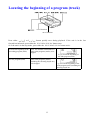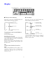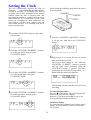
1
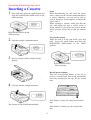
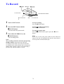
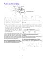
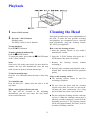
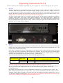
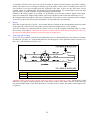
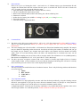
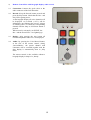
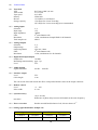
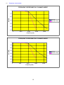
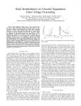
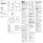
Kraus Messtechnik GmbH Gewerbering 9, D-83624 Otterfing, +49-8024-48737, Fax. +49-8024-5532 – Germany Web: www.kmt-gmbh.com E-mail: [email protected] User Manual D-2/4 Operating instructions tape deck Inserting a Cassette 1 Press and hold down the small button and Notes When disconnecting the unit from the power source, make sure the cassette compartment door is closed. Otherwise, you may not be able to close it afterward. If this happens, reconnect the power source. When inserting a cassette, make sure that the side with which the tape is visible inside is facing upward. If you insert the cassette upside down, you may not be able to take the cassette out. slide the HOLD/PUSH OPEN-switch to the OPEN position. HOLD/PUSH OPEN-switch While pressing 2 3 To eject the cassette While the unit is in the stop mode, press and hold down the small button and slide the HOLD/PUSH OPEN-switch to the OPEN position. Open the cassette compartment door. Insert a cassette with the window facing upward. HOLD/PUSH OPEN While pressing Record-protect shutter Slide the record-protect shutter to the left to protect a recorded tape from being accidentally erased by recording on the tape for the second time. 4 Close the cassette compartment door. If the shutter is open, you cannot record on the tape The cassette will be loaded automatically. If the shutter is closed, you can record on the tape 2 To Record SP/LP out of function out of function 1 2 3 HOLD/PHUSH OPEN REC out of function REC Insert a DAT cassette To stop recording Press the STOP-button. Press the REC button and the ❙❙ PAUSE-button. The unit enters the pause mode. To pause recording momentarily Press the ❙❙ PAUSE-button. Press either the ¾ PLAY-or the ❙❙ PAUSE-button. The recording starts. Notes The recording cannot be started by just pressing the REC button, instead, the unit enters the recording monitor mode. The unit can enters the recording monitor mode whether the record-protect shutter of the cassette is open or not. Recording is possible only when the shutter is closed. To cancel the pause mode Press the ❙❙ PAUSE-button again or press the ¾ PLAYbutton. Notes If the unit is left in the pause mode for more than five minutes, the unit will automatically enter the stop mode in order to protect its head and the tape. 3 Notes on Recording SP/LP out of function out of function HOLD/PHUSH OPEN REC out of function REC Do not leave any unrecorded parts on a DAT tape. If there is a blank (unrecorded) part left on a DAT tape, the absolute time* will not be written thereafter. Also, when the tape is being fastforwarded or rewound, it will stop at that point. In order not to leave any unrecorded parts on a tape while recording, observe the following: To avoid any accidental operation (Hold function) Slide this switch to the HOLD position to avoid any accidental operation while the unit is set in a particular operational mode. z If you intent to continue to record on a tape which is partially recorded, make sure that you find the end of the previous recording first, then start the new recording from that point without leaving any unrecorded gap. (If you fast-forward the tape, if should automatically stop where the previous recording has ended.) This signal indicates the beginning of a recorded program (track). By reading these start ID signals, the unit can cue the beginnings of the recorded programs (tracks) automatically. *The absolute time indicates the elapsed time from the beginning of the tape and the current position of the tape which is written digitally. The absolute time will be automatically written when you record a DAT tape for the very first time and cannot be erased once written. (In the HOLD Position are all switches locked!) .................................................................................... Start ID tape transport direction program (track) program (track) program (track) start ID To write the start IDs automatically while recording This start codes are set by each new recording, also by using the "Pause button" by recording. To write the start IDs manually while recording While recording, press the REC button at the point where you wish to write the start ID. When you record to the end of a DAT tape The tape automatically rewinds to the beginning and will stop there. (Auto-rewind function) Note While writing the start IDs, the W R I T E indication comes on and the START-ID - indicator flashes for about nine seconds. While the unit is set in this mode, no operational buttons other than the STOP button will function. 4 Playback out of function 1 2 Insert a DAT cassette Cleaning the Head Press the ¾ PLAY-button. Playback starts. The SP/LP switch is out of function. Prolonged operation may cause contamination of the head. To make the best possible recording and playback, we recommend you to clean the head periodically, using the cleaning cassette DT-1OCL (not supplied)*. To stop playback Press the STOP-button. How to use the cleaning cassette 1 Insert the cleaning cassette as you would a normal DAT cassette. To pause playback momentarily Press the ❙❙ PAUSE-button. To cancel the mode, press either the ❙❙ PAUSE-button 2 Press the ¾ PLAY button, then press the 3 STOP button after about 10 seconds. or the ¾ PLAY-button. 3 Remove the cleaning cassette without Notes rewinding it. If the unit is left in the pause mode for more than five minutes, the unit will automatically enter the stop 4 Proceed with recording and playback with a mode in order to protect its head and the tape. normal DAT cassette and check the playback quality. To fast forward the tape Press the ¾¾/¾¾I button when the unit is in the stop Notes on the cleaning cassette mode. z The cleaning cassette cannot be used for recording or playback. To rewind the tape Press the I½½/½½ - button when the unit is in the z Do not clean the head with the cleaning stop mode. cassette more than five times in succession. Cleaning the head continuously for a long When a tape is played back to the end period of time may cause wear to the head. The tape will be rewound to the beginning automatically and the unit enters the stop mode. z Do not rewind the cleaning cassette each time (Auto-rewind function) you use it. When the cleaning cassette tape is taken up (wound) completely, rewind it to the beginning and reuse it. The cleaning cassette can be used approximately 200 times, with 10 seconds of cleaning each time. 5 Locating the beginning of a program (track) out of function out of function Press either ¾¾/¾¾I or I½½/½½ button quickly once during playback. If the unit is in the fast forward/rewind mode, press either the ¾¾/¾¾I or I½½/½½ button once. Or if the unit is in the stop mode, press either the ¾¾/¾¾I or I½½/½½ button twice. To locate the beginning of the succeeding program (track) To locate the beginning of the previous program (track) Press ¾¾/¾¾I the same number of times as the programs (tracks) to be skipped. E.g. to locate the beginning of the fifth program (track) Press ¾¾/¾¾I the same number of times as the programs (tracks) (including the currently played one) to be skipped. E. g. to locate the beginning of the fourth program (track) including the currently played one 6 Display Day/AM/PM-indicator Tape counter/clock/message indicator z The tape counter indications z Clock display Each time you press the COUNTER button, the display changes cyclically as follows: Each time you press the CLOCK button, the display changes cyclically as follows: Tape counter (normale display) RECORDED TIME* (date of the recording) Absolute time RECORDED TIME* (time of the recording) Remaining time of tape Current date (year, month, date) To reset the tape counter (normal display) to Current time (hour, minute, secound) 00H00M00S Press the RESET button. *The RECORDED TIME will not be displayed while the unit is in the recording, recording monitor, or pause mode. Remaining time of the tape The remaining time left on the tape will normally come on after about 16 seconds of commencing playback in the SP mode. However, there may be some aberration in the amount of time displayed which depends upon the tape you use. Note The tape counter should not be used as a clock What is being displayed on the counter is not completely accurate in terms of displaying the current time. Therefore, do not use the tape counter as a clock. 7 Setting the Clock The unit automatically registers the date of recording (year/month/date/day/hour/minute/ second) at the time of recording. The date of recording can be then displayed on the display window while the unit is playing back, fast forwarding/rewinding or cueing/reviewing a tape (Date function). It is essential to set the clock before any recordings are made. Otherwise, the date function will not work properly and the correct date and time of a recording will not be registered on the tape. Proceed with the following steps while the unit is in the stop mode. 1 Press the CLOCK/SET button for more than four seconds. 5 Press the COUNTER/- and RESET/+ buttons to set the day, then press the CLOCK/SET button. 2 Press the COUNTER/- and RESET/+ buttons to set the year digits, then press the CLOCK/SET button. 6 Repeat steps 2 to 4 to set the correct current time (hour/minute/second). The second digits change to "00" when the COUNTER/- or RESET/+ button is pressed and the clock starts activating when the CLOCK/SET button is pressed. Therefore, synchronize the clock by pressing either - or + button with the radio time signal etc. 3 Press the COUNTER/- and RESET/+ buttons to set the month digits, then press CLOCK/SET-button. The flashing will stop and the clock will start activating. 4 Press the COUNTER/- and RESET/+ buttons To cancel the procedure Press the STOP button. The clock display will return to the previous time display. However, if you have proceeded to step 6, the year, month, day and date will be set. to set the date digits, then press the CLOCK/SET button. 12/24 hour display To select either the 12-hour or the 24-hour clock display. Press the RESET button for more than two seconds. 8 Precautions On Safety Should any solid object of liquid fall into the unit, unplug the unit and have it checked by qualified personal before operating it any further. On Installation Do not install the unit in a location near heat sources such as radiators or air ducts, or in a place subject to direct sunlight and excessive dust. On Moisture Condensation If the unit is brought directly from a cold to a warm location, moisture may condense inside the unit. In such a condition, the tape may adhere to the head drum and can be damaged, or the unit may not operate properly (the 6-indicator has come on). Always remove the DAT cassette from the unit when the unit is not to be used for an extended period of time. If moisture is present Operating buttons and controls may not function properly. The unit may shut off. 9 Operating instructions D-2/4 Please read the user manual regarding the drive, page two, before starting up the system! 1) Power on: The D2-4 does not have a special power-switch. It is powered on, as soon as the power supply is connected. Attention: Make sure you input the correct power supply voltage. It is 10 up to 18V or 18 up to 32V DC. If it is to low, the DAT recorder may not start up or the commands do not work properly. In this case it can happen, that after activating the record mode, the tape start moving but stops after three seconds. If the supply voltage is to high, the internal fuse will be destroyed immediately. The DAT recorder needs about 5 to 6 seconds to load the cassette. The mux-mode is equal the last used after switching on the power. The record of the analogue channels in two channel mux-mode is realized on channel one and two ( in four channel mux-mode on all channels). The current mux-mode is displayed by the corresponding LED on the front of the DAT recorder. During the replay the recorded mux-mode is also displayed, but it is not possible to change it. 2) Record: Check the write-protection at the cassette, press and hold down the small button and slide the HOLD/PUSH OPEN, insert the cassette with the window facing upward and close the cassette compartment door. The cassette will be loaded automatically. Press "REC", and the D2/16 is in a waiting status, (it still doesn't record). In this mode the system is working as if you are recording, except that the tape doesn't move. It enables you to use the system as a normal signal conditioning unit as front-end to the PC, in order to visualize the channels without making a recording. Please ask for our digital interface and software for PC’s and notebooks. See following table regarding sample rates, mux-mode and signal band width. Total sample rate Mux mode 96kS/s 2-channel 4-channel Channel sample rate 48kS/s 24kS/s Cut off frequency = analogue band width 16kHz 8kHz Attention: Analog input is on the left side and the output on right side of the DAT recorder.. The overload LED’s (OVL) indicate which channel input level exceed ±5V. By pressing the reset switch to the left, you can reset the display (make sure it is not overloaded any more). Please only use the corresponding tool. By pressing „PAUSE“ the tape is ready for immediate recording. The second time you press "Pause", the pause mode stops and the tape moves again, (REC + play status). Simultaneously the start code is recorded. Attention: It takes about 9 seconds to record the start code, simultaneously together with the data, ( you see "START ID" blinking on the display). During this time it is not allowed to stop the tape, because the start code won't be completely recorded and you may not find it later on. 10 At each REC START a new start code will be recorded. In order to find interesting events after recording, further start codes can be set during recording by pressing "REC". Please notice, ascending start codes are only possible if you start recording from the beginning of the tape. In this case the start codes will be counted, stored as a PGM-number and displayed in the PGM-window. We recommend to secure the tape after recording, (with the switch) to avoid overwriting of important data. Parallel to the analog signals, it's possible, via PCM-input, to record and reproduce digital TTL signals. These are continuously sampled with 192kHz, and can be reproduced with a transition time delay of 5 µs. By using the handy microphone, with built in loudspeaker, it's possible to make comments to the recording. To record, just press the switch on the microphone. The reproduction is automatically. 3) Replay: Insert the cassette and press "PLAY". All recorded data are available at the corresponding connector output on the right side of the DAT recorder. Input overload will not be displayed (no „OVL“ display). All DAT recorders are calibrated with an accuracy of 0,1% over the complete measuring range. To check the accuracy, notice that the calibration data must be recorded and after them read in Play mode. (In this way the signal pass through the complete system from input to output filter.) 4) Event triggered recording In case it is not possible to start the record manual there are two internal different event detectors available, in OR-mode, (via pin 1 or 3 of the PWR-connector) for this purpose. These potentials must be between +3V and +30V, with a duration of at least 2 sec. Pin 1 3 Data recording time as long as the input pulse is high, at least 15 sec. as long as the input pulse is high, plus 1 minute. Attention: Before inserting the cassette, make sure that no write protection is done. The message TAPE PROTECT will appear on the display but not via the remote control.. This remote control can only start and stop the RECORD mode. If the DAT-Recorder is currently in PLAY mode, the remote control signals will be ignored. 11 5) Date and time: How to set it, pls. see "Setting the clock" . One built in 3,6 V Lithium battery (type Sonnenschein SL340) supplies the internal date and time counter after the power is switched off. It has a life time of about one year. To replace it please execute the following steps: 1. Open the battery compartment door, (unscrew the two screws). 2. Cut the wiring directly at the battery socket. 3. Remove the isolation and disconnect the battery pins with an soldering iron. 4. Mount new isolation. 5. Solder the new battery pins (middle red wiring is plus, left green wiring is minus). 6. Fasten the isolation. 7. Close the battery compartment door. 6) Common hints: 6.1 The D2/4 needs a DC-power supply with 10 - 18V or 18 - 32V (Pwr-connector Pin 2 Plus and Pin 5 Minus). There is no ground protection. When you connect a power supply unit, pls. follow the common safety instructions! The total sampling rate is fixed at 96kS/s. All channels are filtered and simultaneously sampled. The sample rate per channel is depending on the mux-mode. Just divide 96 kHz by the number of channels and you get the sample rate per channel, (two channel mux-mode 48kS/s each channel and four channel mux-mode 24kS/s each. To avoid anti aliasing effects, the filters will automatically be switched to the max. cut off frequency (a third of the sampling rate) in record as well as in replay-mode. The resolution is 12 bit (72dB Dynamic), that means at an amplitude of ± 5V =10V your LSB is 2,5 mV (4096 steps). The drive processor recognizes cassettes with a max. runtime of 2 hours (tape length of 60 m). Cassettes with a length of 90m. (3 hours runtime) can be used but the displayed remaining time will not be correctly detect from the processor. In this case see the displayed tape length. 6.2 6.3 7) Drive modifications The tape recorder was modified because of technical reasons. That is why following switches and functions are out of function: 1. SP/LP 2. REC LEVEL 3. VOLUME +/4. AVLS 8) Very important remarks. We recommend: Use only high quality cassettes and clean the head periodically, using the cleaning cassette DT-10CL (not supplied). If you get any errors, the most common reason is a bad tape or a dirty head. In most cases it's enough, just to cut the power for a second to eliminate trouble effects. At high temperatures, caused by sun or missing ventilation, it is possible that the D2/4 produce short errors after a longer runtime. To avoid this problem, switch off the D2/16 when you do not use it. 12 9) Remote Control Box with bargraph display, audio record. 9.1 Connection: Connect the 9pole cable at the audio connector of the DAT-Recorder. 9.2 Record: Keep the Record button pressed and press the Play button. Check that the Rec.- and Play LED’s getting active. At the bargraph display all active channels will be displayed. An overload (>±5V), will be indicated by one flashing sign or more. It keeps on flashing above or below the corresponding channel until the Stop or OVL/Reset button is pressed. When record is activated by an EVENT, the Rec.- and the Event-LED’ s are lightning up. 9.3 Replay: After pressing the play button all recorded amplitudes and OVL’s are displayed. 9.4 Audio: By pressing the Voice/Record button, at the side of the remote control, during „Record-Mode“, the speech channel with comments will be recorded together with the data. Replay is automatically done in „Play mode. The remote control is also available without a bargraph display in shape of a „handy“ 13 10) Technical Data 10.1 Tape deck Tape Track width Tape speed Density Bit rate Storage capacity DAT-tape width 3,81 mm ca. 13,6 µm 8,15 mm/s 61kbit/inch 1,536 Mbit/s or 192 kByte/s 1,38 GByte for 2 hours recording 2,07 GByte for 3 hours recording (not recommended) 10.2 Analog inputs Selection Input range Input impedance Filter Resolution Total sample rate 2, 4 ±5V 100kΩ 8th-order Butterworth 12 Bit, simultaneous Sample/Hold for all channels 96kS/s 10.3 Analog Outputs Selection Output range Output impedance Filter Resolution 2, 4 ±5V 2 Ω, max. 10mA 8th-order Butterworth 12 Bit, simultaneous for all channels 10.4 Digital PCM Input/Output Sample rate 192 kHz Remaining transition delay appr. 5 µs Level TTL 10.5 Audio channel Signal bandwidth 100 Hz ... 3000 Hz 10.6 Interface output Level Cable length TTL 2-3m The conversion of the data stream into IF16 word parallel format is done in the output connector. 10.7 Remote control Level Pulse width +3 ... 30V ≥ 2 sec. 10.8 System accuracy ±0,1% at 0 Hz, Difference of phase delay between all channels at the same frequency max.0,05°. 10.9 Error correction -10 Double encoded Reed Solomon Code, bit error better 10 10.10 Analog signal bandwidth / Sample rate Signal band width Total scanning rate 2 channels 4 channels 2 channels 4 channels 16 kHz 8 kHz 48 kHz 24 kHz 14 10.11 Power supply Input Power consumption Option 10 – 18 or 18 - 32 V DC appr. 10W Transformer with an input 250V AC (50Hz) and output 15V DC 10.12 Dimensions 150 x 85 x 75 mm without shock absorber 10.13 Weight appr. 1,5 kg without shock absorber 10.14 Environmental Operating temperature range-5 °C to +45 °C Storage temperature range -20 °C to +60 °C Humidity 20 ... 80% non condensing Vibration 5g Mil Standard 810C, Curve C Shock 10g in all directions 11) Pin-connection 15 Frequency characteristic FREQUENCY RESPONSE IN 2 CHANNEL MODE 0 -10 Gain dB -20 Record -30 Record & Play -40 -50 -60 0 8000 16000 24000 32000 Frequency (Hz) FREQUENCY RESPONSE IN 4 CHANNEL MODE 0 -10 -20 Gain (dB) 12) -30 Record Record & Play -40 -50 -60 -70 0 4000 8000 12000 Frequency (Hz) 16 16000