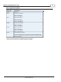
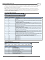
1
TIWAY Host Adapter
Driver Help
© 2012 Kepware Technologies
TIWAY Host Adapter Driver Help
2
Table of Contents
Table of Contents
2
TIWAY Host Adapter Driver Help
5
Overview
5
Host Adapter Setup
7
Device Setup
10
Modem Setup
10
Addressing Options
10
Data Types Description
12
Address Descriptions
13
Standard Data Type Addressing
13
SS Bit Definitions
13
Alarm Addressing
14
AVF Bit Definitions
15
ACF Bit Definitions
16
16
Loop Addressing
Loop V-Flag Bit Definitions
18
LCF Bit Definitions
18
LRSF Bit Definitions
19
UHA Status & Control Addressing
19
Macro Addressing
20
UNILink Macros
21
Defining Macros
23
Defining Read Macros
23
Defining Link Macros
25
Macro Enable/Disable Status
26
Macro Response Status Word (MRSW)
26
Error Descriptions
27
28
Address Validation
Address '<address>' is out of range for the specified device or register
28
Array size is out of range for address '<address>'
28
Array support is not available for the specified address: '<address>'
28
Data Type '<type>' is not valid for device address '<address>'
29
Device address '<address>' contains a syntax error
29
Device address '<address>' is Read Only
29
Missing address
29
29
Serial Communications
Communications error on '<channel name>' [<error mask>]
29
COMn does not exist
30
www. kepware.com
TIWAY Host Adapter Driver Help
3
COMn is in use by another application
30
Error opening COMn
30
Unable to set comm parameters on COMn
30
31
Device Status Messages
Device '<device name>' is not responding
31
31
Device Specific Messages
Adapter reporting command timeout - Error 0x001. Reconfiguring adapter
31
Adapter reporting HIU not initialized - Error 0x100B. Reconfiguring adapter
31
Adapter reporting unrecognized command - Error 0x0084. Reconfiguring adapter
31
Host adapter not responding
32
Secondary device '<device name>' no longer connected to network. Reconnecting secondary
32
32
Read Errors
Unable to read block starting at '<address>' on device '<device name>': Adapter Error <code>
32
Unable to read block starting at '<address>' on device '<device name>': Adapter Error <code>. Block
deactivated
33
Unable to read block starting at '<address>' on device '<device name>': Framing Error
33
Unable to read block starting at '<address>' on device '<device name>': Secondary Error: <code>
33
Unable to read block starting at '<address>' on device '<device name>': Secondary Error: <code>. Block
deactivated
33
Unable to read tag '<address>' on device '<device name>': Task Error: <code>
34
Unable to read tag '<address>' on device '<device name>': Task Error: <code>. Tag deactivated
34
34
Write Errors
Unable to write to '<address>' on device '<device name>'
34
Unable to write tag '<address>' on device '<device name>': Adapter Error <code>
35
Unable to write tag '<address>' on device '<device name>': Framing Error
35
Unable to write tag '<address>' on device '<device name>': Secondary Error: <code>
35
Unable to write tag '<address>' on device '<device name>': Task Error: <code>
35
36
Macro Specific Messages
Adapter reporting macro link error - Error 0x2020. Trigger Macro cannot be configured for auto-enable
36
Macro tag address '<address>' is invalid given new macro definition. Tag deactivated
36
The macro referenced in tag address '<address>' is no longer available. Tag deactivated
37
Unable to Read Macro with Source ID '<id>', macro #'<num>' on '<device name>': Adapter Error <code>
37
Unable to Read Macro with Source ID '<id>', macro #'<num>' on '<device name>': Adapter Error <code>.
Block deactivated
37
Unable to Read Macro with Source ID '<id>', macro #'<num>' on '<device name>': Framing Error
38
Unable to Read Macro with Source ID '<id>', macro #'<num>' on '<device name>': MRSW Error <code>
Unable to Read Macro with Source ID '<id>', macro #'<num>' on '<device name>': MRSW Error <code>.
Block deactivated
Unable to Read Macro with Source ID '<id>', macro #'<num>' on '<device name>': Secondary Error
www. kepware.com
38
38
TIWAY Host Adapter Driver Help
4
<code>
39
Unable to Read Macro with Source ID '<id>', macro #'<num>' on '<device name>': Secondary Error
<code>. Block deactivated
39
Unable to Read Macro with Source ID '<id>', macro #'<num>' on '<device name>': Task Error <code>
39
Unable to Read Macro with Source ID '<id>', macro #'<num>' on '<device name>': Task Error <code>.
Tag deactivated
40
40
XML Error Messages
XML Loading Error: An existing link macro already has this macro number: '<num>'. Link macro not
loaded
40
XML Loading Error: An existing read macro already has this macro number: '<num>'. Link macro not
loaded
40
XML Loading Error: An existing read macro already has this macro number: '<num>'. Read macro not
loaded
41
XML Loading Error: Invalid value found. Link macro not loaded
41
XML Loading Error: Invalid value found. Read macro not loaded
41
XML Loading Error: Link macro linked to missing read macro '<num>'. Link macro not loaded
42
XML Loading Error: Read macro(s) missing from file. Link macro(s) not loaded
42
Error Codes
42
Adapter Error Codes
42
Secondary Error Codes
44
Task Error Codes
45
MRSW Termination Codes
45
Index
47
www. kepware.com
TIWAY Host Adapter Driver Help
5
TIWAY Host Adapter Driver Help
Help version 1.021
CONTENTS
Overview
What is the TIWAY Host Adapter Driver?
Host Adapter Setup
How do I configure the Host Adapter that the driver will be using?
Device Setup
How do I configure a device for use with this driver?
Data Types Description
What data types does this driver support?
UNILink Macros
How do I create and use macros with this driver?
Address Descriptions
How do I address a data location on a TI secondary device?
Error Descriptions
What error messages does the driver produce?
Error Codes
What error codes do the adapter/secondary devices return?
Overview
The TIWAY Host Adapter Driver provides an easy and reliable way to connect TIWAY Host Adapter devices to OPC
Client applications, including HMI, SCADA, Historian, MES, ERP, and countless custom applications. It is intended
for use with a TIWAY 1 Host Adapter or a TIWAY 1 UNILINK Host Adapter using the NITP protocol. The driver
makes requests to the Host Adapter unit, which then forwards the request on to the actual network. When a
response is received, the Host Adapter returns the response to the driver. The driver can be configured to control
the behavior of the adapter, or the adapter can be configured with DIP switches on the unit to tell the driver to
respect these settings. Once connected to a TIWAY 1 network, the driver can communicate with up to 254 secondary devices.
Host Adapters can be configured as MHIUs or HIUs. MHIUs are capable of implementing Network Manager duties
for the TIWAY network. If a TIWAY network is already up and running, the new Host Adapter should be configured as an HIU. Having multiple Network Managers on a network will cause erratic behavior: it may also lose
data because the each unit will struggle for control.
Note: For a complete description of the Host Adapter unit and the various operating modes, refer to the TIWAY I
UNILINK Host Adapter User's Manual.
www. kepware.com
TIWAY Host Adapter Driver Help
6
www. kepware.com
TIWAY Host Adapter Driver Help
7
Host Adapter Setup
The driver uses the Host Adapter unit to gain access to the TIWAY network. During a session, the driver may
need to initialize, configure, and reset the adapter. Some of the adapter settings must be set using the unit's DIP
switches, whereas other settings can be made through the Channel Properties. The Host Adapter switch settings
that must be configured are as follows:
1. NITP Protocol Selection: Switches 1 of DIP switch 1.
2.
Host Port Baud Rate: Switches 5 to 8 of DIP switch 2. The DIP switch baud rate should match the baud
rate that was selected in the Communications tab of Channel Properties. This is the baud rate the driver
will use to communicate with the adapter over the RS232 link.
Note: For information on all adapter DIP switch settings, commands, and parameters, refer to the TIWAY 1 UNILINK Host Adapter User's Manual.
Creating a New TIWAY Host Adapter Channel
When creating a new TIWAY Host Adapter channel, users may find it easier to accept the default settings in the
Channel Wizard and then edit the settings later through the Channel Properties.
Note 1: If the driver finds that the adapter is not configured at power up or after a reset, the Configure Adapter
(Command 20) will be sent along with the parameters specified in the Adapter tab of Channel Properties.
Note 2: If an irrecoverable error condition is encountered, the driver may need to issue a software reset adapter
command. Once the adapter has had time to reset, the driver will proceed with the recovery sequence.
Adapter
Descriptions of the parameters are as follows:
l
Adapter Type: This parameter specifies the type of adapter to use for communications with the TIWAY
network. Options include the UNILINK adapter or the TIWAY 1 adapter.
www. kepware.com
TIWAY Host Adapter Driver Help
8
Note: When the TIWAY 1 adapter is selected, all other adapter parameters will be disabled because they
are not needed.
l
Host Configuration: This parameter specifies the host configuration. Options include MHIU, HIU, MHIU
- EHA Mode, or HIU - EHA Mode. It is recommended that MHIU be selected when the adapter is configured
for MHIU. Selecting HIU when the adapter is configured for MHIU will result in faulty data.
Note: If the adapter is powered-up, reset, or the Configure Adapter command is successfully processed,
the driver will issue a Configure HIU (Command 11) along with the parameters specified in the HIU tab of
Channel Properties. If the default settings are used, the driver will send the command without any parameters. If the EHA mode is the selected adapter, the Configure Adapter command will not be sent.
l
Macro Storage Memory: This parameter specifies the macro storage memory. Options include Default,
16 KB, 24 KB, and Max. Available. The default setting is Default.
l
Maximum Secondary Address: This parameter specifies the maximum secondary address for the
TIWAY network that will be controlled by the Host Adapter. The valid range is 1 to 254. The default setting
is 254.
l
Secondary Address: This parameter specifies the secondary address for the TIWAY network that will be
controlled by the Host Adapter. The default setting is 1.
HIU
This tab will be disabled if the Use Hardware Defaults check box is enabled.
Network Manager
The Network Manager settings are only available when the specified adapter is MHIU. Its parameters will be disabled if the Use Hardware Default Settings check box is enabled.
www. kepware.com
TIWAY Host Adapter Driver Help
9
Note: If the adapter powers up, resets, or successfully processes the Configure Adapter command, the driver
will issue a Configure Network Manager (Command 30). The Network Manager, Channel A, and Channel B parameters will be sent along with this command. The driver will send the command without any parameters if the
default settings were chosen.
Important: Channel B parameters are only available for editing when Enable Auto Redundant Media is
selected.
Tested DIP Switch Settings
The following switch settings have been tested and found to work with this driver.
DIP Switch 1
1 up 2-4 down
5-6 up
7 down
8 up 9 down
10 up
DIP Switch 2
1 up 2-4 down
5-6 up
7 down
8 up 9-10 down
N/A.
www. kepware.com
TIWAY Host Adapter Driver Help
10
Device Setup
Supported Devices
TIWAY secondary device.
Communication Protocol
Non-Intelligent Terminal Protocol (NITP).
Supported Communication Parameters
Baud Rate: 300, 600, 1200, 2400, 9600, 19200, or 38400.
Stop Bits: 1.
Parity: Odd.
Data Bits: 7.
Flow Control
When using an RS232/RS485 converter, the type of flow control that is required depends on the needs of the converter. Some converters do not require any flow control whereas others require RTS flow. For more information
on flow requirements, refer to the converter's documentation. It is recommended that an RS485 converter that
provides automatic flow control be used.
Note: Select RTS, DTR.
Ethernet Encapsulation
This driver supports Ethernet Encapsulation, which allows the driver to communicate with serial devices
attached to an Ethernet network using a terminal server (such as the Lantronix DR1). This mode may be invoked
through the COM ID tab in Channel Properties. For more information, refer to the server's help documentation.
Cable Connections
Modem Setup
This driver supports modem functionality. For more information, please refer to the topic "Modem Support" in the
OPC Server Help documentation.
Addressing Options
www. kepware.com
TIWAY Host Adapter Driver Help
11
Description of the option is as follows:
l
Bit Order for V, K, WX, WY, SS: This option specifies the order in which bits will be presented to V, K,
WX, WY, and SS memory types when bit accessed. "MSB" means "Most Significant Bit" and "LSB" means
"Least Significant Bit". The default setting is Bit 1 is LSB.
Note: DWord follows the same bit order logic as Words, but has 32 bits instead of 16.
Bit 1 Is MSB of Word
MSB
1
LSB
2
3
4
5
6
7
8
9
10
11
12
13
14
15
16
Bit 1 Is LSB of Word
MSB
16
LSB
15
14
13
12
11
10
See Also: Address Descriptions
www. kepware.com
9
8
7
6
5
4
3
2
1
TIWAY Host Adapter Driver Help
12
Data Types Description
Data Type
Description
Boolean
Single bit
Word
Unsigned 16 bit value
bit 0 is the low bit
bit 15 is the high bit
Short
Signed 16 bit value
bit 0 is the low bit
bit 14 is the high bit
bit 15 is the sign bit
DWord
Unsigned 32 bit value
bit 0 is the low bit
bit 31 is the high bit
Long*
Signed 32 bit value
bit 0 is the low bit
bit 30 is the high bit
bit 31 is the sign bit
Float**
32 bit floating point value
The driver interprets two consecutive registers as a floating-point
value by making the second register the high word and the first register the low word.
*Long is the same as Double in the TISOFT programming software.
**Float is the same as Real in the TISOFT programming software.
www. kepware.com
TIWAY Host Adapter Driver Help
13
Address Descriptions
Address specifications vary depending on the model in use. Select a link from the following list to obtain specific
address information for the model of interest.
Standard Data Type Addressing
Alarm Addressing
Loop Addressing
UHA Status & Control Addressing
Macro Addressing
Standard Data Type Addressing
The driver supports the following addresses for use with a Series 500 NIM only. The default data type for each
address type is shown in bold.
Note: For more information on applicable PLCs, refer to device specific documentation.
Address Type
Format
Range
Data Types
Access
Discrete Inputs
X<address>
1-65536
Boolean
Read/Write
Discrete Outputs
Y<address>
1-65536
Boolean
Read/Write
Word Inputs**
WX<address>
WX<address>.<bit>
1-65536
Bit 1-16*
Short, Word, Long, DWord, Float
Boolean
Read/Write
Read/Write
Word Outputs**
WY<address>
WY<address>.<bit>
1-65536
Bit 1-16*
Short, Word, Long, DWord, Float
Boolean
Read/Write
Read/Write
Discrete Control
C<address>
1-65536
Boolean
Read/Write
Word Memory**
V<address>
V<address>.<bit>
1-65536
Bit 1-16*
Short, Word, Long, DWord, Float
Boolean
Read/Write
Read/Write
Constant Memory**
K<address>
K<address>.<bit>
1-65536
Bit 1-16*
Short, Word, Long, DWord, Float
Boolean
Read Only
Read Only
Secondary System Status**
SS<address>
SS<address>.<bit>
1-65536
Bit 1-32*
Long, DWord, Float
Boolean
Read Only
Read Only
SS Bit Definitions
Timer/Counter Preset
TCP<address>
1-65536
Short, Word
Read/Write
Timer/Counter Current
TCC<address>
1-65536
Short, Word
Read/Write
Drum Step Preset
DSP<address>
1 -256
Byte
Read/Write
Drum Step Current
DSC<address>
1-256
Byte
Read/Write
Drum Count Preset
DCP<drum>.<step>
drum 1-256
step 1-16
Short, Word
Read/Write
*For more information, refer to Addressing Options.
**Addresses of this type may be used as arrays. To specify an array address, append "[rows][cols]" to the end
of an address. If only [cols] is specified, [rows] will default to 1. The maximum array size, which is determined
by the multiplication of rows and columns, is 64 Words.
Note: The maximum array size for SS and alarm types is specified in DWords; thus, the maximum array size is
32 DWords. Furthermore, the actual number of addresses available for each type depends on the configuration of
the PLC. If the driver finds that an address is not present in the device at Runtime, the driver will post an error
message and remove the tag from its scan list.
SS Bit Definitions
Secondary System Status Data Element Format - Word #1(LSW)
MSB
ABCD
LSB
EFGH
IJKL
Element
SS bit
Description
A
17
*
B
18
*
C
19
*
MNOP
www. kepware.com
TIWAY Host Adapter Driver Help
D
20
*
E
21
*
F
22
*
G
23
*
H
24
*
I
25
*
J
26
*
K
27
*
L
28
*
M
29
*
N
30
*
O
31
*
P
32
*
14
*Each bit set to 1 indicates that the corresponding bit in Word #2 is a reported status.
Word #2(MSW)
MSB
ABCD
LSB
EFGH
IJKL
MNOP
Status Bit
SS bit
Description
A
1
0 = NIM in REMOTE mode
1 = NIM in LOCAL mode
B
2
0 = P/C System in REMOTE mode
1 = P/C Sytem in LOCAL mode
C
3
Undefined
D
4
Undefined
E
5
Undefined
F
6
Undefined
G
7
Undefined
H
8
Undefined
I
9
Undefined
J
10
Undefined
K
11
Undefined
L
12
Undefined
M
13
Undefined
N
14
Undefined
O
15
Undefined
P
16
Undefined
Alarm Addressing
The driver supports the following Analog Alarm addresses for use with a Series 500 NIM only. The default data
type for each address type is shown in bold.
Note: For more information on applicable PLCs, refer to device specific documentation.
Address Type
Format
Range
Data Types
Access
Alarm Variable Flag
AVF<alarm>
AVF<alarm>.<bit>
1-256
Bit 1-16
Short, Word
Boolean
Read Only
1-256
Bit 1-32
Long, DWord
Boolean
Read/Write
AVF Bit Definitions
Alarm Control Flag
ACF<alarm>
ACF<alarm>.<bit>
ACF Bit Definitions
Alarm PV High Limit*
APVH<alarm>
1-256
Float
Read/Write
Alarm PV Low Limit*
APVL<alarm>
1-256
Float
Read/Write
www. kepware.com
TIWAY Host Adapter Driver Help
15
Alarm Process Variable*
APV<alarm>
1-256
Float
Read/Write
Alarm High Alarm Limit*
AHA<alarm>
1-256
Float
Read/Write
Alarm Low Alarm Limit*
ALA<alarm>
1-256
Float
Read/Write
Alarm Orange Dev. Alarm Limit*
AODA<alarm>
1-256
Float
Read/Write
Alarm Yellow Dev. Alarm Limit*
AYDA<alarm>
1-256
Float
Read/Write
Alarm Sample Rate*
ATS<alarm>
1-256
Float
Read/Write
Alarm Setpoint*
ASP<alarm>
1-256
Float
Read/Write
Alarm Error*
AERR<alarm>
1-256
Float
Read Only
Alarm High-High Alarm Limit*
AHHA<alarm>
1-256
Float
Read/Write
Alarm Low-Low Alarm Limit*
ALLA<alarm>
1-256
Float
Read/Write
Alarm Rate of Change Alarm*
ARCA<alarm>
1-256
Float
Read/Write
Alarm Setpoint High Limit
ASPH<alarm>
1-256
Float
Read/Write
Alarm Setpoint Low Limit
ASPL<alarm>
1-256
Float
Read/Write
Alarm Alarm Deadband
AADB<alarm>
1-256
Float
Read/Write
Alarm Raw High Alarm Limit
AHAR<alarm>
1-256
Short, Word
Read/Write
Alarm Raw Low Alarm Limit
ALAR<alarm>
1-256
Short, Word
Read/Write
Alarm Raw Process Variable
APVR<alarm>
1-256
Short, Word
Read/Write
Alarm Raw Orange Deviation
AODAR<alarm>
1-256
Short, Word
Read/Write
Alarm Raw Yellow Deviation
AYDAR<alarm>
1-256
Short, Word
Read/Write
Alarm Raw Setpoint
ASPR<alarm>
1-256
Short, Word
Read/Write
Alarm Raw Alarm Deadband
ADBR<alarm>
1-256
Short, Word
Read/Write
Alarm Raw Error
AERRR<alarm>
1-256
Short, Word
Read Only
Alarm Raw High-High Alarm Limit
AHHAR<alarm>
1-256
Short, Word
Read/Write
Alarm Raw Low-Low Alarm Limit
ALLAR<alarm>
1-256
Short, Word
Read/Write
Alarm Raw Setpoint Low Limit
ASPLR<alarm>
1-256
Short, Word
Read/Write
Alarm Raw Setpoint High Limit
ASPHR<alarm>
1-256
Short, Word
Read/Write
Alarm MSW of Alarm C Flags
ACFH<alarm>
1-256
Short, Word
Read/Write
Alarm LSW of Alarm C Flags
ACFL<alarm>
1-256
Short, Word
Read/Write
Alarm ACK Flag
AACK<alarm>
1-256
Short, Word
Read Only
*Addresses of this type may be used as arrays. To specify an array address, append "[rows][cols]" to the end of
an address. If only [cols] is specified, [rows] will default to 1. The maximum array size, which is determined by
the multiplication of rows and columns, is 64 Words.
Note: The maximum array size for SS and alarm types is specified in DWords; thus, the maximum array size is
32 DWords. Furthermore, the actual number of addresses available for each type depends on the configuration of
the PLC. If the driver finds that an address is not present in the device at Runtime, the driver will post an error
message and remove the tag from its scan list.
AVF Bit Definitions
Analog Alarm Variable Flag Data Element Format - MSB LSB
MSB
LSB
ABCD
EFGH
IJKL
MNOP
Element
AVF bit
Description
A
1
Enable alarm
B
2
Disable alarm
C
3
Analog variable in high high alarm
D
4
Analog variable in high alarm
E
5
Analog variable in low alarm
F
6
Analog variable in low low alarm
G
7
Analog variable in yellow deviation alarm
H
8
Analog variable in orange deviation alarm
I
9
Analog variable in rate-of-change alarm
J
10
Analog variable in broken transmitter alarm
K
11
Analog alarm is overrunning
www. kepware.com
TIWAY Host Adapter Driver Help
16
L
12
Not used, set to 0
M
13
Not used, set to 0
N
14
Not used, set to 0
O
15
Not used, set to 0
P
16
Not used, set to 0
ACF Bit Definitions
Analog Alarm Control Flag Data Element Format
MSB
ABCD
LSB
EFGH
IJKL
MNOP
QRST
UVWX
Element
ACF bit
Description
A
1
PV scale 20% offset
B
2
Take square root of PV
C
3
Monitor HIGH/LOW alarm
D
4
Monitor HIGH-HIGH/LOW-LOW alarm
E
5
Monitor deviation alarms
F
6
Monitor rate-of-change alarm
G
7
Monitor broken transmitter alarm
H
8
0 = Local setpoint
1 = Remote setpoint
I
9
Unused, set to 0
J
10
Unused, set to 0
K
11
Unused, set to 0
L
12
Unused, set to 0
M
13
Unused, set to 0
N
14
Unused, set to 0
O
15
Unused, set to 0
P
16
Unused, set to 0
Q
17
Unused, set to 0
R
18
Unused, set to 0
S
19
Unused, set to 0
T
20
Unused, set to 0
U
21
Unused, set to 0
V
22
Unused, set to 0
W
23
Unused, set to 0
X
24
Unused, set to 0
Y
25
Special function program number
Z
26
Special function program number
a
27
Special function program number
b
28
Special function program number
c
29
Special function program number
d
30
Special function program number
e
31
Special function program number
f
32
Special function program number
YZab
cdef
Note: If a bit is set to 1, the corresponding action is enabled. If a bit is set to 0, the corresponding action is disabled.
Loop Addressing
The driver supports the following PID Loop addresses for use with a Series 500 NIM only. The default data type
for each address type is shown in bold.
Note: For more information on applicable PLCs, consult device specific documentation.
www. kepware.com
TIWAY Host Adapter Driver Help
17
Address Type
Format
Range
Data Types
Access
Loop Gain*
LKC<loop>
1-256
Float
Read/Write
Loop Reset*
LTI<loop>
1-256
Float
Read/Write
Loop Rate*
LTD<loop>
1-256
Float
Read/Write
Loop High Alarm Limit*
LHA<loop>
1-256
Float
Read/Write
Loop Low Alarm Limit*
LLA<loop>
1-256
Float
Read/Write
Loop Process Variable*
LPV<loop>
1-256
Float
Read/Write
Loop PV High Limit*
LPVH<loop>
1-256
Float
Read/Write
Loop PV Low Limit*
LPVL<loop>
1-256
Float
Read/Write
Loop Orange Dev. Alarm Limit*
LODA<loop>
1-256
Float
Read/Write
Loop Yellow Dev. Alarm Limit*
LYDA<loop>
1-256
Float
Read/Write
Loop Sample Rate*
LTS<loop>
1-256
Float
Read/Write
Loop Setpoint*
LSP<loop>
1-256
Float
Read/Write
Loop Output*
LMN<loop>
1-256
Float
Read/Write
Loop Status (V) Flags
Reference the Loop VFlag address 1-256
Long, DWord
in V-Memory as specified in the
Loop.
Bit 1-32 Boolean
Read/Write
Loop V-Flag Bit Definitions
Loop Control (C) Flags*
LCF<loop>
1-256
Long, DWord
LCF<loop>.<bit>
Bit 132
Boolean
LRSF<loop>
1-256
Short, Word
LRSF<loop>.<bit>
Bit 116
Boolean
Read/Write
LCF Bit Definitions
Loop Ramp/Soak Status Flags*
Read Only
LRSF Bit Definitions
Loop Error*
LERR<loop>
1-256
Float
Read Only
Loop Bias*
LMX<loop>
1-256
Float
Read/Write
Loop High-High Alarm Limit*
LHHA<loop>
1-256
Float
Read/Write
Loop Low-Low Alarm Limit*
LLLA<loop>
1-256
Float
Read/Write
Loop Rate of Change Alarm*
LRCA<loop>
1-256
Float
Read/Write
Loop Setpoint High Limit
LSPH<loop>
1-256
Float
Read/Write
Loop Setpoint Low Limit
LSPL<loop>
1-256
Float
Read/Write
Loop Alarm Deadband
LADB<loop>
1-256
Float
Read/Write
Loop Raw High Alarm Limit
LHAR<loop>
1-256
Short, Word
Read/Write
Loop Raw Low Alarm Limit
LLAR<loop>
1-256
Short, Word
Read/Write
Loop Raw Process Variable
LPVR<loop>
1-256
Short, Word
Read/Write
Loop Raw Orange Deviation
LODAR<loop>
1-256
Short, Word
Read/Write
Loop Raw Yellow Deviation
LYDAR<loop>
1-256
Short, Word
Read/Write
Loop Raw Output
LMNR<loop>
1-256
Short, Word
Read/Write
Loop Raw Setpoint
LSPR<loop>
1-256
Short, Word
Read/Write
Loop Raw Error
LERRR<loop>
1-256
Short, Word
Read Only
Loop Raw High-High Alarm Limit
LHHAR<loop>
1-256
Short, Word
Read/Write
Loop Raw Low-Low Alarm Limit
LLLAR<loop>
1-256
Short, Word
Read/Write
Loop Raw Alarm Deadband
LADBR<loop>
1-256
Short, Word
Read/Write
Loop Raw Bias
LMXR<loop>
1-256
Short, Word
Read/Write
Loop Raw Setpoint Low Limit
LSPLR<loop>
1-256
Short, Word
Read/Write
Loop Raw Setpoint High Limit
LSPHR<loop>
1-256
Short, Word
Read/Write
Loop MSW of Loop C Flags
LCFH<loop>
1-256
Short, Word
Read/Write
Loop LSW of Loop C Flags
LCFL<loop>
1-256
Short, Word
Read/Write
Loop Derivative Gain Limit Coef.
LKD<loop>
1-256
Short, Word
Read/Write
Loop Ramp/Soak Step Number
LRSN<loop>
1-256
Short, Word
Read/Write
Loop Alarm Ack Flags
LACK<loop>
1-256
Short, Word
Read Only
www. kepware.com
TIWAY Host Adapter Driver Help
18
*Addresses of this type may be used as arrays. To specify an array address, append "[rows][cols]" to the end of
an address. If only [cols] is specified, [rows] will default to 1. The maximum array size, which is determined by
the multiplication of rows and columns, is 64 Words.
Note: The maximum array size for SS and alarm types is specified in DWords; thus, the maximum array size is
32 DWords. Furthermore, the actual number of addresses available for each type depends on the configuration of
the PLC. If the driver finds that an address is not present in the device at Runtime, the driver will post an error
message and remove the tag from its scan list.
Loop V-Flag Bit Definitions
Loop Variable Flag Data Element Format - MSB LSB
MSB
LSB
ABCD
EFGH
IJKL
MNOP
Element
Loop V-Flag Bit
Description
A
1
Loop Mode: If set to 1, the loop is in auto mode. If set to 0, the loop is in manual mode.
B
2
Loop Cascade: If set to 1, the loop is in closed cascade. If set to 0, the loop is in open
cascade.
C
3
Error Deviation: If set to 1, the loop is in positive error deviation. If set to 0, the loop is
in negative error deviation.
D
4
PV High High Alarm: If set to 1, the process variable is in high high alarm. If set to 0,
the process variable is not in high high alarm.
E
5
PV High Alarm: If set to 1, the process variable is in high alarm. If set to 0, the process variable is not in high alarm.
F
6
PV Low Alarm: If set to 1, the process variable is in low alarm. If set to 0, the process
variable is not in low alarm.
G
7
PV Low Low Alarm: If set to 1, the process variable is in low low alarm. If set to 0, the
process variable is not in low low alarm.
H
8
Yellow Band: If set to 1, the loop deviation is in the yellow band. If set to 0, the loop
deviation is not in the yellow band.
I
9
Orange Band: If set to 1, the loop deviation is in the orange band. If set to 0, the loop
deviation is not in the orange band.
J
10
PV Rate of Change Alarm: If set to 1, the loop PV is in rate of change alarm. If set to 0,
the loop PV rate of change is not in alarm (for 560/565 P/Cs).
K
11
PV Broken Transmitter Alarm: If set to 1, the loop PV has a broken transmitter. If set to
0, the loop PV does not have a broken transmitter (for 560/565 P/Cs).
L
12
Loop Overrun: If set to 1, the loop is overrunning its time allocation. If set to 0, the
loop is not overrunning its time allocation (for 560/565 P/Cs).
M
13
Spare: Set to 0.
N
14
Spare: Set to 0.
O
15
Spare: Set to 0.
P
16
Spare: Set to 0.
LCF Bit Definitions
Loop Control Flag Data Element Format
MSB
ABCD
LSB
EFGH
IJKL
MNOP
QRST
UVWX
Element
LCF Bit
Description
A
1
PV scale 20% offset
B
2
Take square root of PV
C
3
Monitor HIGH/LOW alarm
D
4
Monitor HIGH-HIGH/LOW-LOW alarm
E
5
Monitor deviation alarms
F
6
Monitor rate-of-change alarm
G
7
Monitor broken transmitter alarm
H
8
Use PID position algorithm
www. kepware.com
YZab
cdef
TIWAY Host Adapter Driver Help
19
I
9
Use PID velocity algorithm
J
10
Direct acting
K
11
Rever acting
L
12
Error squared control
M
13
Error deadband control
N
14
Lock auto/manual mode
O
15
Lock cascade mode
P
16
Lock setpoint
Q
17
Unknown
R
18
Execute Special Function program on the PV
S
19
Execute Special Function program on the setpoint
T
20
Freeze error sum on output out-of-range
U
21
Ramp/soak on the setpoint
V
22
Output is bipolar
W
23
Process variable is bipolar
X
24
Enable derivative gain limiting
Y
25
Number of the SF program that will be executed
Z
26
Number of the SF program that will be executed
a
27
Number of the SF program that will be executed
b
28
Number of the SF program that will be executed
c
29
Number of the SF program that will be executed
d
30
Number of the SF program that will be executed
e
31
Number of the SF program that will be executed
f
32
Number of the SF program that will be executed
Note: If the bit is set to 1, the option is enabled. If the bit is set to 0, the option is disabled.
LRSF Bit Definitions
Ramp/Soak Status Data Element Format MSB-LSB
MSB
LSB
ABCD
EFGH
IJKL
MNOP
Element
LRSF Bit
Description
A
1
All programmed steps finished (1=yes)
B
2
Soak timer in wait state with PV out of range (1=yes)
C
3
Unused, set to 0
D
4
Unused, set to 0
E
5
Unused, set to 0
F
6
Unused, set to 0
G
7
Unused, set to 0
H
8
Unused, set to 0
I
9
Ramp/soak step number currently executing
J
10
Ramp/soak step number currently executing
K
11
Ramp/soak step number currently executing
L
12
Ramp/soak step number currently executing
M
13
Ramp/soak step number currently executing
N
14
Ramp/soak step number currently executing
O
15
Ramp/soak step number currently executing
P
16
Ramp/soak step number currently executing
UHA Status & Control Addressing
The driver supports the following UHA status and control addresses. The default data type for each address type
is shown in bold.
Address Description
Format
www. kepware.com
Range
Data Types
Access
TIWAY Host Adapter Driver Help
20
Error communicating with adapter?
_AdapterError
N/A
Boolean
Read Only
Secondary connected to network?
_SecondaryLog<sec. id>
1-254
Boolean
Read Only
Software Reset of UHA.
_SoftReset
N/A
Boolean
Write Only
HardwareReset of UHA.
_HardReset
N/A
Boolean
Write Only
Note: 1 _AdapterError will notify users when there is a loss of communication between the OPC Server and the
UHA.
Note 2: _Error for each device (secondary) will notify users when there is a loss of communication between the
UHA and the secondary in question.
Macro Addressing
Macro Data Addressing (Applicable to Standard & Trigger Macros Only)
Macros are independent network requests stored and scheduled by the HIU function. The TIWAY Host Adapter
Driver not only allows for macro creation and download, but also provides direct access to macro memory for reading. It is important to reiterate that macro memory is Read Only. Linked macros are inherently Read/Write (store
and forward) but the act of writing is done transparently without user intervention. In fact, the memory of the
Action Macro (write portion) is neither readable nor writable from an OPC tag standpoint and so cannot be
addressed.
See Also: UNILink Macros
1. To start, define the macro. For more information, refer to Defining Macros.
2. Next, create an OPC tag that references the macros statically or dynamically. The syntax is #<Macro
number><memory type><address>, where:
l
#: This item signifies that the following tag is a macro tag.
l
<Macro number>: This item is the user-defined macro number as entered during macro creation.
l
<Memory type>: This item is the memory type of the given macro, which must match the memory type entered during macro creation.
l
<Address>: This item is the address of interest, which must fall in the address range entered
during macro creation.
Macro Data Addressing Examples
Example One: Defined Macro
Macro Number
Source ID
Secondary ID
Address
3
2
15
V200-V200
Macro Reference
Address
Valid?
Explanation
#2V200
False
Incorrect macro number
#3V200
True
N/A
#3V201
False
Address out of range
Example Two: Defined Macro
Macro Number
Source ID
Secondary ID
Address
18
1
2
X17-X32
Macro Reference
Address
Valid?
Explanation
#1X20
False
Incorrect macro number
#18X20
True
N/A
#18V20
False
Incorrect address type
www. kepware.com
TIWAY Host Adapter Driver Help
21
Macro Status & Control Addressing
The driver supports the following macro addresses.
Format
Address Description
Range Data Types
Access
_InitializingMacros
True while driver is creating/setting up macros
in the UHA.
N/A
Boolean
Read Only
_MacroMemAvail
Memory available for macros.
N/A
Long,
DWord
Read Only
_MacroBuffAvail
Number of macro buffers available.
N/A
Short, Word
Read Only
_SourceIDAvail
Number of Source IDs available.
N/A
Short, Word
Read Only
_SourceIDActive<Source ID>
Source ID active?
1-254
Boolean
Read Only
_Enable#<macro num>
Enable/disable given macro.
1-254
Boolean
Write Only
_EnableStatus#<macro num>
Response code from last macro enable/disable
of given macro.*
1- 254
Short, Word
Read Only
_BufferNum#<macro num>
Buffer number for given macro.
1-254
Short, Word
Read Only
_MRSW#<macro num>
Last MRSW for given macro.**
1-254
Short, Word
Read Only
*For more information, refer to Macro Enable/Disable Status.
**For more information, refer to Macro Response Status Word (MRSW).
UNILink Macros
Macros are TIWAY network requests that are stored and scheduled for independent processing by the HIU.
Because macros are Read requests (except for Link Macros, which also involve a write request), they are ideal for
performing non real-time monitoring of network data. By moving non-critical monitoring to macros, the HIU
resources are free to perform time-critical monitoring and control.
Requirements
1. Selection of the UNILINK model.
2. Selection of the MHIU or HIU configuration mode.
Note: Macros are not supported in the Emulate Host Adapter mode.
In the TIWAY Host Adapter Driver, macros are defined via the Graphical User Interface (GUI) in the OPC server.
Tags can then be created that reference data obtained from these defined macros. If such tags are referenced
from a client, the driver will download the macros defined in the GUI. Only those macros that are enabled will
present valid data to these tags. Macro definitions can be edited or removed while the client is referencing it with
the understanding that tags referencing such macros can break. In this case, the macro reference tag is requesting a piece of data that the macro is no longer retrieving. Caution should be taken when editing macros so that
macro-referencing tags do not fall outside the macro range (data block).
Macro Logistics
l
A macro and its data are stored in a macro buffer. A macro number identifies each macro buffer.
l
The number of bytes required (memory usage) for a macro buffer primarily depends on the number of
elements requested to be read as defined in the macro. The UNILINK Host Adapter User Manual explains
how to calculate such usage but is not necessary since this usage can be monitored through Macro
Status & Control Addressing tags in the server.
l
The maximum amount of memory to set aside for all macro buffers defined is set in the Adapter tab in
Channel Properties. Typical values are 16 KB and 24 KB. This is not the amount of memory available for
each macro but the amount available for all macros combined.
l
A maximum of 254 macro buffers can be allocated. Thus, 254 macros can be defined.
l
In order for macros to be executed, they must be assigned to a task (which is commonly called a
source).
l
A source is a collection of macros executed under the same time slice, independent of other UHA
resources. For example, if there are 10 macros defined in a source in a round robin manner, each macro
will be allocated 1/10 of a second for every second elapsed. Each source is identified by a Source ID.
l
A maximum of 32 sources can be defined. Since each source is its own independent task, this implies
there can be 32 sources operating simultaneously.
Macro Performance vs. Memory
There are a few rules that can be implemented in order to maximize macro performance. In general, performance
is achieved through a sacrifice in memory resources and vice versa. They are as follows:
www. kepware.com
TIWAY Host Adapter Driver Help
22
l
Each macro should request as much data as necessary, which increases the macro buffer size needed
and utilizes available memory resources (macro memory set aside).
l
Macros should be spread evenly across as many sources as possible. Since the time slice is shared within
each source, it's best to have few macros per source. For instance, if there are a total 32 macros to be
defined, assign one macro to a source. This utilizes all sources available, but each macro will have maximum performance.
Read Macros
Read Macros have two purposes: to read a block of data and to make it available for access. Throughout this help
file, this will be called a standard Read Macro. Macros are the "store" in "store and forward" for macro linking. In
linking, the Read Macro gathers the data that the link will take and forward or write to another memory location.
This is called a Trigger Macro. With this in mind, a Read Macro can be defined for two reasons or one, depending
on the application. For more information on linking, refer to Link Macros.
There are three essential steps for using Read Macros: defining, downloading, and referencing.
Defining the Macro
Read Macros are defined via a Graphical User Interface. For more information, refer to Defining Macros.
Downloading the Macro
Read Macros are automatically downloaded. Any time a Read Macro definition is added, edited, or removed, the
driver will automatically reinitialize the macro. For more information, refer to the UNILINK Host Adapter User Manual.
1. To start, allocate the Source IDs. Each Source ID referenced in the macro definitions will be allocated in
the UHA. All others will be de-allocated.
2. Next, allocate macro Storage Buffers. For each Read Macro, a buffer will be allocated and assigned a
buffer number in the UHA under the Source ID specified for that macro. The size of the buffer depends on
the request protocol packet size and the response protocol packet size, since both are stored in the macro
buffer.
3. Then, define the macros. For each Read Macro, the read request protocol packet will be assigned to the
macro buffer that was previously assigned under the Source ID specified for that macro.
Referencing the Macro
Referencing a macro means accessing the data gathered by the macro. This is accomplished by requesting the
macro response data given the macro buffer number assigned and Source ID specified for that macro. The driver
automatically performs this action when a client tag is referencing a macro. Macro response data is essentially a
block of data, which may contain one or many elements. The key to referencing this block from a client/server tag
standpoint is to first specify the macro of interest and then the specific address within the block. For example, if a
macro with macro number 4 were defined to gather V1 to V10, then the macro data block would be a 10-word
block. If V7 were of interest, simply request for V7 in macro 4. The addressing for such a request is #4V7. For
more information, refer to Macro Addressing.
Link Macros
A Link Macro forwards or writes data originating from a Trigger Macro to a location on the same or different secondary on the network. Throughout this help file, the term Link Macro refers to the Trigger and Action Macro pair.
There are three essential steps for using Link Macros: defining, downloading, and referencing.
Defining the Macro
Link Macros are defined via a Graphical User Interface. For more information, refer to Defining Macros.
Downloading the Macro
Link Macros are automatically downloaded, and will be reinitialized anytime a Link Macro definition is added,
edited, or removed. For more information, refer to the UNILINK Host Adapter User Manual.
1. To start, allocate the Source IDs. Each Source ID referenced in the macro definitions will be allocated in
the UHA. All others will be de-allocated.
2. Next, allocate macro Storage Buffers. For each Action Macro, a buffer will be allocated and assigned a
buffer number
in the UHA under the Source ID specified for that macro. The size of the buffer depends on the request
protocol packet size and the response protocol packet size, since both are stored in the macro buffer.
www. kepware.com
TIWAY Host Adapter Driver Help
23
3. Then, define the macros. For each Action Macro, the write request protocol packet will be assigned to the
macro buffer previously assigned under the Source ID specified for that macro.
4. Next, link macros. Each Action Macro will be linked to the Trigger Macro defined in the Link Macro.
Referencing the Macro
Trigger Macros can be referenced as described in the Read Macros section above. Action Macros cannot be referenced. As previously mentioned, both the Trigger and Action Macro must be initially disabled. Thus, when
beginning to use macros, the Trigger Macro must be manually enabled using the _Enable#<Trigger Macro
num> address.
Defining Macros
Macro Setup
This channel-level dialog is the breakout point for defining Read and Link Macros. It has two purposes: first, to
list the macros defined and second, to provide an interface to add, edit and remove Read and Link Macros. The
image below shows the Macro Setup dialog.
Note: Adding and editing macros utilizes the same dialog used to define or redefine. Removing a macro simply
removes the defined macro from the list and, more importantly, from the driver. All listed macros will be downloaded to the device.
Defining Read Macros
Read Macros are defined and redefined through the common interface shown below.
www. kepware.com
TIWAY Host Adapter Driver Help
24
Each of the variables shown above are described in more detail in the table below.
Note: Each variable retains its definition and rules regardless of whether the macro is new or being edited.
Variable
Description/Rules
Default
User Defined
Macro
Number
Driver-specific number for identifying a macro, which is used in referencing macro data via OPC
tag address. This number must be unique among both Read and Link Macros.
1
Secondary
Address
Secondary device (i.e. PLC) address for which the given macro applies to.
1
Address Type The data element type to be read in the macro.
V-Memory
Starting
Address
The first data element to be read in the macro
1
Ending
Address
The last data element to be read in the macro. The difference between the starting and ending
addresses define the data block that is the macro.
1
Source ID
The desired Source ID to store and execute this macro from.
1
Re-Issue
Delay
The "minimum reissue" delay time in milliseconds. This specifies the time to wait before reissuing the macro command and only applies to repetitive macros.
1000ms
Freeze Macro
and
Response On
Exception?
An exception occurs when the data retrieved from the secondary differs from the data stored in
False
the macro buffer. If desired, the macro can be configured to disable when such an exception
occurs. This is termed freezing and can be accomplished by selecting the checkbox. This feature
only applies to repetitive macros.
Repetitive?
When this checkbox is selected, the macro will be repetitive. The HIU will automatically reissue
the macro as long as the macro is enabled. Again, if a new response differs from a previous
response, the exception flag is set. When this checkbox is not selected, the macro will be nonrepetitive. When enabled, the macro will be issued, its exception flag set, and automatically be
disabled. Re-enabling the macro will cause a reissue of the macro.
True
Automatically
Enabled?
When this checkbox is selected, the macro will automatically be enabled once downloaded. The
MRSW will be reset to 0 and increment on every issue. When this checkbox is non-selected, the
macro will not be automatically enabled. The MRSW will be set to 0x8001 and will require manual
enabling for use. This is required case for Trigger Macros in a link.
True
www. kepware.com
TIWAY Host Adapter Driver Help
25
Defining Link Macros
Link Macros are defined and redefined through the common interface shown below. They are comprised of two
parts: the Trigger Macro and the Action Macro. The Trigger Macro specifies what will be linked to, whereas the
Action Macro specifies what to do with the data received from the trigger.
Descriptions of the parameters are as follows:
l
User-Defined Macro Number (Trigger): Read Macro that will act as the Trigger Macro, or "store" portion of the "store and forward" process of the link.
l
User Defined Macro Number (Action): Driver-specific number for identifying a macro. This number
must be unique among both Link and Read Macros.
l
Secondary Address: Secondary device (PLC) address to which the Action Macro will "forward" link data.
l
Starting Address: The first data element to be written to on the "forward" portion of the link.
l
Freeze Macro and Response On Exception: An exception occurs
when the data retrieved from the secondary differs from the data
stored in the macro buffer. If desired, the macro can be configured to
disable when such an exception occurs. This is termed freezing and can
be accomplished by selecting the checkbox. This feature only applies to
repetitive macros.
Note: Each variable retains its definition and rules regardless of whether the macro is new or being edited.
Non-Configurable Parameters
Variable
Description/Rules
Address Type
The data element type of the address on the "forward" portion of the link must be the same address type
on the "store" portion, defined by the Trigger Macro.
Ending
Address
Given the block size defined in the Trigger Macro, the ending address is calculated based on the starting
address defined for the Action Macro.
Source ID
Same as Source ID for Trigger Macro.
Re-Issue Delay The Trigger Macro drives the "store and forward" process; thus, the re-issue delay has no meaning for
the Action Macro.
Repetitive?
The Action Macro must be non-repetitive.
Automatically
The Trigger Macro (as well as the Action Macro) must be initially disabled.
www. kepware.com
TIWAY Host Adapter Driver Help
26
Enabled?
Macro Enable/Disable Status
Response Code
Description
0
Macro successfully enabled/disabled.
1
Macro buffer number requested has not been allocated.
2
Macro buffer number specified has a different Source ID than the
one specified.
3
Macro buffer specified is the Action Macro in a Link Macro pair that
cannot be explicitly enabled or disabled.
4
Incorrect command issued.
5
The macro has not been downloaded yet.
6
Macro buffer specified is the Trigger Macro in a Link Macro pair
that cannot be explicitly enabled at this time because the Action
Macro response has not returned.
7
The specified macro buffer cannot be enabled because the secondary device associated with it is offline.
Macro Response Status Word (MRSW)
The MRSW indicates the status of the macro response as well as the number of times the macro has been
updated. Each defined macro has its own MRSW. The table below shows some possible values.
MRSW Values (hex)
Description
0000
This macro has not been executed since the last time
it was enabled.
0001 to 7FFF
The number of times a repetitive macro response
has been updated.
8000 to FFFF
Termination Code: The macro is disabled due to either
an error, an exception, or an explicit disable.
Note: Termination Codes are listed in detail under MRSW Termination Codes.
www. kepware.com
TIWAY Host Adapter Driver Help
27
Error Descriptions
The following error/warning messages may be generated. Click on the link for a description of the message.
Address Validation
Address '<address>' is out of range for the specified device or register
Array size is out of range for address '<address>'
Array support is not available for the specified address: '<address>'
Data Type '<type>' is not valid for device address '<address>'
Device address '<address>' contains a syntax error
Device address '<address>' is Read Only
Missing address
Serial Communications
Communications error on '<channel name>' [<error mask>]
COMn does not exist
COMn is in use by another application
Error opening COMn
Unable to set comm parameters on COMn
Device Status Messages
Device '<device name>' is not responding
Device Specific Messages
Adapter reporting command timeout - Error 0x001. Reconfiguring adapter
Adapter reporting HIU not initialized - Error 0x100B. Reconfiguring adapter
Adapter reporting unrecognized command - Error 0x0084. Reconfiguring adapter
Host adapter not responding
Secondary device '<device name>' no longer connected to network. Reconnecting secondary
Read Errors
Unable to read block starting at '<address>' on device '<device name>': Adapter Error <code>
Unable to read block starting at '<address>' on device '<device name>': Adapter Error <code>.
Block deactivated
Unable to read block starting at '<address>' on device '<device name>': Framing Error
Unable to read block starting at '<address>' on device '<device name>': Secondary Error: <code>
Unable to read block starting at '<address>' on device '<device name>': Secondary Error: <code>.
Block deactivated
Unable to read tag '<address>' on device '<device name>': Task Error: <code>
Unable to read tag '<address>' on device '<device name>': Task Error: <code>. Tag deactivated
Write Errors
Unable
Unable
Unable
Unable
Unable
to
to
to
to
to
write
write
write
write
write
to '<address>' on device '<device name>'
tag '<address>' on device '<device name>':
tag '<address>' on device '<device name>':
tag '<address>' on device '<device name>':
tag '<address>' on device '<device name>':
Adapter Error <code>
Framing Error
Secondary Error: <code>
Task Error: <code>
Macro Specific Messages
Adapter reporting macro link error - Error 0x2020. Trigger Macro cannot be configured for auto-enable
Macro tag address '<address>' is invalid given new macro definition. Tag deactivated
The macro referenced in tag address '<address>' is no longer available. Tag deactivated
Unable to Read Macro with Source ID '<id>', macro #'<num>' on '<device name>': Adapter Error
<code>
Unable to Read Macro with Source ID '<id>', macro #'<num>' on '<device name>': Adapter Error
<code>. Block deactivated
Unable to Read Macro with Source ID '<id>', macro #'<num>' on '<device name>': Framing Error
Unable to Read Macro with Source ID '<id>', macro #'<num>' on '<device name>': MRSW Error
<code>
Unable to Read Macro with Source ID '<id>', macro #'<num>' on '<device name>': MRSW Error
<code>. Block deactivated
www. kepware.com
TIWAY Host Adapter Driver Help
Unable to Read Macro with Source
Error <code>
Unable to Read Macro with Source
Error <code>. Block deactivated
Unable to Read Macro with Source
<code>
Unable to Read Macro with Source
<code>. Tag deactivated
28
ID '<id>', macro #'<num>' on '<device name>': Secondary
ID '<id>', macro #'<num>' on '<device name>': Secondary
ID '<id>', macro #'<num>' on '<device name>': Task Error
ID '<id>', macro #'<num>' on '<device name>': Task Error
XML Error Messages
XML Loading
loaded
XML Loading
not loaded
XML Loading
not loaded
XML Loading
XML Loading
XML Loading
XML Loading
Error: An existing link macro already has this macro number: '<num>'. Link macro not
Error: An existing read macro already has this macro number: '<num>'. Link macro
Error: An existing read macro already has this macro number: '<num>'. Read macro
Error:
Error:
Error:
Error:
Invalid value found. Link macro not loaded
Invalid value found. Read macro not loaded
Link macro linked to missing read macro '<num>'. Link macro not loaded
Read macro(s) missing from file. Link macro(s) not loaded
Address Validation
The following error/warning messages may be generated. Click on the link for a description of the message.
Address Validation
Address '<address>' is out of range for the specified device or register
Array size is out of range for address '<address>'
Array support is not available for the specified address: '<address>'
Data Type '<type>' is not valid for device address '<address>'
Device address '<address>' contains a syntax error
Device address '<address>' is Read Only
Missing address
Address '<address>' is out of range for the specified device or register
Error Type:
Warning
Possible Cause:
A tag address that has been specified statically references a location that is beyond the range of supported locations for the device.
Solution:
Verify the address is correct; if it is not, re-enter it in the client application.
Array size is out of range for address '<address>'
Error Type:
Warning
Possible Cause:
A tag address that has been specified statically is requesting an array size that is too large for the address type or
block size of the driver.
Solution:
Re-enter the address in the client application to specify a smaller value for the array or a different starting point.
Array support is not available for the specified address: '<address>'
Error Type:
Warning
Possible Cause:
www. kepware.com
TIWAY Host Adapter Driver Help
29
A tag address that has been specified statically contains an array reference for an address type that doesn't support arrays.
Solution:
Re-enter the address in the client application to remove the array reference or correct the address type.
Data Type '<type>' is not valid for device address '<address>'
Error Type:
Warning
Possible Cause:
A tag address that has been specified statically has been assigned an invalid data type.
Solution:
Modify the requested data type in the client application.
Device address '<address>' contains a syntax error
Error Type:
Warning
Possible Cause:
A tag address that has been specified statically contains one or more invalid characters.
Solution:
Re-enter the address in the client application.
Device address '<address>' is Read Only
Error Type:
Warning
Possible Cause:
A tag address that has been specified statically has a requested access mode that is not compatible with what the
device supports for that address.
Solution:
Change the access mode in the client application.
Missing address
Error Type:
Warning
Possible Cause:
A tag address that has been specified statically has no length.
Solution:
Re-enter the address in the client application.
Serial Communications
The following error/warning messages may be generated. Click on the link for a description of the message.
Serial Communications
Communications error on '<channel name>' [<error mask>]
COMn does not exist
COMn is in use by another application
Error opening COMn
Unable to set comm parameters on COMn
Communications error on '<channel name>' [<error mask>]
Error Type:
www. kepware.com
TIWAY Host Adapter Driver Help
30
Serious
Error Mask Definitions:
B = Hardware break detected.
F = Framing error.
E = I/O error.
O = Character buffer overrun.
R = RX buffer overrun.
P = Received byte parity error.
T = TX buffer full.
Possible Cause:
1. The serial connection between the host adapter and the Host PC is bad.
2. The communications parameters for the serial connection are incorrect.
Solution:
1. Verify the cabling between the PC and the host adapter.
2. Verify that the specified communications parameters match those of the host adapter.
COMn does not exist
Error Type:
Fatal
Possible Cause:
The specified COM port is not present on the target computer.
Solution:
Verify that the proper COM port has been selected.
COMn is in use by another application
Error Type:
Fatal
Possible Cause:
The serial port assigned to a channel is being used by another application.
Solution:
1. Verify that the correct port has been assigned to the channel.
2. Shut down any other applications that are using the COM port assigned to this channel.
Error opening COMn
Error Type:
Fatal
Possible Cause:
The specified COM port could not be opened due an internal hardware or software problem on the target computer.
Solution:
Verify that the COM port is functional and may be accessed by other Windows applications.
Unable to set comm parameters on COMn
Error Type:
Fatal
Possible Cause:
The serial parameters for the specified COM port are not valid.
Solution:
Verify the serial parameters and make any necessary changes.
www. kepware.com
TIWAY Host Adapter Driver Help
31
Device Status Messages
The following error/warning messages may be generated. Click on the link for a description of the message.
Device Status Messages
Device '<device name>' is not responding
Device '<device name>' is not responding
Error Type:
Serious
Possible Cause:
1. The secondary with the specified network address is not connected to the TIWAY network.
2. The serial connection between the device and the Host PC is broken.
3. The response from the device took longer to receive than the amount of time specified in the "Request Timeout"
device setting.
4. The communications parameters for the serial connection are incorrect.
Solution:
1. Verify that the secondary device is connected and on line.
2. Verify the cabling between the PC and the host adapter.
3. Increase the Request Timeout setting so that the entire response can be handled.
4. Verify that the baud rate selected matches that of the host adapter.
5. Make sure that odd parity and 7 data bits are selected.
6. Make sure that RTS, DTR flow control is selected.
Device Specific Messages
The following error/warning messages may be generated. Click on the link for a description of the message.
Device Specific Messages
Adapter reporting command timeout - Error 0x001. Reconfiguring adapter
Adapter reporting HIU not initialized - Error 0x100B. Reconfiguring adapter
Adapter reporting unrecognized command - Error 0x0084. Reconfiguring adapter
Host adapter not responding
Secondary device '<device name>' no longer connected to network. Reconnecting secondary
Adapter reporting command timeout - Error 0x001. Reconfiguring adapter
This error will occur after a request times out in the HIU. The Network Manager possibly went offline due to a malfunction or its maximum poll delay is longer than the host command timeout. Ensure that the maximum poll delay
is shorter than the host command timeout.
When this condition is encountered, the driver will perform a soft reset of the adapter to properly reconfigure it.
The command timeout is on the order of 30-60 seconds. If the problem is remedied, the next occurrence of this
condition will perform the soft reset and communications will be resolved.
See Also:
Adapter Error Codes
Adapter reporting HIU not initialized - Error 0x100B. Reconfiguring adapter
This error will occur after the HIU has been reset or powered cycled while the driver was communicating with it.
This condition results in the driver having to do a software reset of the adapter to properly reconfigure it.
See Also:
Adapter Error Codes
Adapter reporting unrecognized command - Error 0x0084. Reconfiguring
adapter
Users will receive this message if the driver forms a request that the adapter does not recognize. This usually
occurs after the adapter is reset. To solve this, have the driver perform a software reset of the adapter so that it
will recognize it properly.
www. kepware.com
TIWAY Host Adapter Driver Help
32
See Also:
Adapter Error Codes
Host adapter not responding
Error Type:
Serious. This error occurs when the driver times out waiting on a response from the host adapter.
Possible Cause:
1. The host adapter has been reset.
2. The host adapter is not turned on.
2. The serial connection between the host adapter and the Host PC is broken.
3. The communications parameters for the serial connection are incorrect.
Solution:
1. If the host adapter was manually reset, the driver will recover and reconnect.
2. Verify that the host adapter is on.
2. Verify the cabling between the PC and the host adapter.
3. Verify that the baud rate selected matches that of the host adapter.
4. Make sure that odd parity and 7 data bits are selected.
5. Make sure that RTS, DTR flow control is selected.
Secondary device '<device name>' no longer connected to network. Reconnecting secondary
This message will appear if a secondary device the driver was previously communicating with is disconnected
from the TIWAY network. The driver will periodically attempt to reconnect to the device to reestablish communication. This message will be accompanied by a 'Device is not responding' error message.
See Also:
Device '<device name>' is not responding
Read Errors
The following error/warning messages may be generated. Click on the link for a description of the message.
Read Errors
Unable to read block starting at '<address>' on device '<device name>': Adapter Error <code>
Unable to read block starting at '<address>' on device '<device name>': Adapter Error <code>.
Block deactivated
Unable to read block starting at '<address>' on device '<device name>': Framing Error
Unable to read block starting at '<address>' on device '<device name>': Secondary Error: <code>
Unable to read block starting at '<address>' on device '<device name>': Secondary Error: <code>.
Block deactivated
Unable to read tag '<address>' on device '<device name>': Task Error: <code>
Unable to read tag '<address>' on device '<device name>': Task Error: <code>. Tag deactivated
Unable to read block starting at '<address>' on device '<device name>':
Adapter Error <code>
Error Type:
Warning
Possible Cause:
1. The address does not exist in the device.
2. The device could not perform the read operation.
Solution:
1. Check to make sure that the address exists in device.
2. The adapter returned an error during the last block read. All tags in this block will be invalidated but will
remain in the scan list.
See Also:
Adapter Error Codes
www. kepware.com
TIWAY Host Adapter Driver Help
33
Unable to read block starting at '<address>' on device '<device name>':
Adapter Error <code>. Block deactivated
Error Type:
Warning
Possible Cause:
1. The address does not exist in the device.
2. The device could not perform the read operation.
Note:
The adapter returned an error during the last block read. Based on the error, all tags in this block will be deactivated (removed from the scan list).
See Also:
Adapter Error Codes
Unable to read block starting at '<address>' on device '<device name>': Framing Error
Error Type:
Warning
Possible Cause:
The adapter with device <device name> responded with incorrect data possibly due to transmission errors or
device malfunction.
Solution:
1. Place adapter on less noisy network if that is the case.
2. Increase the request timeout.
Note:
All tags in this block will be invalidated but will remain in the scan list.
Unable to read block starting at '<address>' on device '<device name>': Secondary Error: <code>
Error Type:
Warning
Possible Cause:
1. The address does not exist in the device.
2. The device could not perform the read operation.
Note:
The secondary device <device name> returned an error during the last block read. All tags in this block will be
invalidated but will remain in the scan list.
See Also:
Secondary Error Codes
Unable to read block starting at '<address>' on device '<device name>': Secondary Error: <code>. Block deactivated
Error Type:
Warning
Possible Cause:
1. The address does not exist in the device.
2. The device could not perform the read operation.
Note:
The secondary device <device name> returned an error during the last block read. Based on the error, all tags in
this block will be deactivated (removed from the scan list).
www. kepware.com
TIWAY Host Adapter Driver Help
34
See Also:
Secondary Error Codes
Unable to read tag '<address>' on device '<device name>': Task Error:
<code>
Error Type:
Warning
Possible Cause:
1. The address does not exist in the device.
2. The device could not perform the read operation.
Note:
The secondary device <device name> returned a task-specific error during the last task read. Read Loop (Task
0x76) and Read Analog Alarm (Task 0x79) are used to read loop and alarm tags that are not accessible through
the Read Block NIM Primitive (0x20). This tag will be invalidated but will remain in the scan list.
See Also:
Task Error Codes
Unable to read tag '<address>' on device '<device name>': Task Error:
<code>. Tag deactivated
Error Type:
Warning
Possible Cause:
1. The address does not exist in the device.
2. The device could not perform the read operation.
Note:
The secondary device <device name> returned a task-specific error during the last task read. Read Loop (Task
0x76) and Read Analog Alarm (Task 0x79) are used to read loop and alarm tags that are not accessible through
the Read Block NIM Primitive (0x20). Based on the error, the tag will be deactivated (removed from the scan list).
See Also:
Task Error Codes
Write Errors
The following error/warning messages may be generated. Click on the link for a description of the message.
Write Errors
Unable
Unable
Unable
Unable
Unable
to
to
to
to
to
write
write
write
write
write
to '<address>' on device '<device name>'
tag '<address>' on device '<device name>':
tag '<address>' on device '<device name>':
tag '<address>' on device '<device name>':
tag '<address>' on device '<device name>':
Adapter Error <code>
Framing Error
Secondary Error: <code>
Task Error: <code>
See Also:
Adapter Error Codes
UNILink Macros
Macro Addressing
Unable to write to '<address>' on device '<device name>'
Error Type:
Warning
Possible Cause:
1. The serial connection between the device and the Host PC is broken.
2. The communications parameters for the serial connection are incorrect.
www. kepware.com
TIWAY Host Adapter Driver Help
35
3. The named device may have been assigned an incorrect Network ID.
Solution:
1. Verify the cabling between the PC and the PLC device.
2. Verify that the specified communications parameters match those of the device.
3. Verify that the Network ID given to the named device matches that of the actual device.
Note:
This error will normally be preceded by a 'Device not responding' message and data for this address will already
be invalid in the client application. The error occurs if the driver is not able to communicate with the adapter or
secondary device.
See Also:
Device '<device name>' is not responding
Unable to write tag '<address>' on device '<device name>': Adapter Error
<code>
Error Type:
Warning
Possible Cause:
The adapter returned an error during the last write operation.
See Also:
Adapter Error Codes
Unable to write tag '<address>' on device '<device name>': Framing Error
Error Type:
Warning
Possible Cause:
The adapter with device <device name> responded with incorrect data during the last write operation, possibly
due to transmission errors or device malfunction.
Solution:
1. Place adapter on a less noisy network (if that is the case).
2. Increase the request timeout.
Unable to write tag '<address>' on device '<device name>': Secondary Error:
<code>
Error Type:
Warning
Possible Cause:
The secondary device <device name> returned an error during the last write operation.
See Also:
Secondary Error Codes
Unable to write tag '<address>' on device '<device name>': Task Error:
<code>
Error Type:
Warning
Possible Cause:
The secondary device <device name> returned a task-specific error during the last task write operation. Write
Loop (Task 0x60) and Write Analog Alarm (Task 0x64) are used to write to loop and alarm tags that are not accessible through the Write Block NIM Primitive (0x30).
See Also:
www. kepware.com
TIWAY Host Adapter Driver Help
36
Task Error Codes
Macro Specific Messages
The following error/warning messages may be generated. Click on the link for a description of the message.
Macro Specific Messages
Adapter reporting macro link error - Error 0x2020. Trigger Macro cannot be configured for auto-enable
Macro tag address '<address>' is invalid given new macro definition. Tag deactivated
The macro referenced in tag address '<address>' is no longer available. Tag deactivated
Unable to Read Macro with Source ID '<id>', macro #'<num>' on '<device name>': Adapter Error
<code>
Unable to Read Macro with Source ID '<id>', macro #'<num>' on '<device name>': Adapter Error
<code>. Block deactivated
Unable to Read Macro with Source ID '<id>', macro #'<num>' on '<device name>': Framing Error
Unable to Read Macro with Source ID '<id>', macro #'<num>' on '<device name>': MRSW Error
<code>
Unable to Read Macro with Source ID '<id>', macro #'<num>' on '<device name>': MRSW Error
<code>. Block deactivated
Unable to Read Macro with Source ID '<id>', macro #'<num>' on '<device name>': Secondary
Error <code>
Unable to Read Macro with Source ID '<id>', macro #'<num>' on '<device name>': Secondary
Error <code>. Block deactivated
Unable to Read Macro with Source ID '<id>', macro #'<num>' on '<device name>': Task Error
<code>
Unable to Read Macro with Source ID '<id>', macro #'<num>' on '<device name>': Task Error
<code>. Tag deactivated
Adapter reporting macro link error - Error 0x2020. Trigger Macro cannot be configured for auto-enable
Error Type:
Warning
Possible Cause:
It is invalid to configure a Trigger Macro to be auto-enabled. Trigger Macros must be explicitly enabled.
Solution:
Deselect "Automatically Enable?" in the Link Macro definition.
See Also:
UNILink Macros
Macro tag address '<address>' is invalid given new macro definition. Tag deactivated
Error Type:
Warning
Possible Cause:
The macro definition for the given macro tag has been changed. The address type, address range, or a combination of the two have been edited such that the address <address> is no longer valid.
Solution:
1. Change the address type/address range so the address <address> is valid.
2. Remove the macro tag from the client. This macro tag will be deactivated (removed from the scan list).
See Also:
UNILink Macros
Macro Addressing
www. kepware.com
TIWAY Host Adapter Driver Help
37
The macro referenced in tag address '<address>' is no longer available. Tag
deactivated
Error Type:
Warning
Possible Cause:
The macro definition for the given macro tag has been removed or macro number changed. As a result, the
address <address> is no longer valid.
Solution:
1. Re-add the macro definition.
2. Change the macro number so the address <address> is valid.
3. Remove this macro tag from the client. This macro tag will be deactivated (removed from the scan list).
See Also:
UNILink Macros
Macro Addressing
Unable to Read Macro with Source ID '<id>', macro #'<num>' on '<device
name>': Adapter Error <code>
Error Type:
Warning
Possible Cause:
1. The address specified in the given macro (macro num/Source ID) does not exist in the device.
2. The device could not perform the read operation.
Solution:
Check to make sure that the address exists in the device.
Note:
The adapter returned an error during the last gather macro response for the given macro. All tags in this macro
block will be invalidated but will remain in the scan list.
See Also:
Adapter Error Codes
UNILink Macros
Macro Addressing
Unable to Read Macro with Source ID '<id>', macro #'<num>' on '<device
name>': Adapter Error <code>. Block deactivated
Error Type:
Warning
Possible Cause:
1. The address specified in the given macro (macro num/Source ID) does not exist in the device.
2. The device could not perform the read operation.
Solution:
Check to make sure that the address exists in the device.
Note:
The adapter returned an error during the last gather macro response for the given macro. Based on the error, all
tags in this macro block will be deactivated (removed from the scan list).
See Also:
Adapter Error Codes
UNILink Macros
Macro Addressing
www. kepware.com
TIWAY Host Adapter Driver Help
38
Unable to Read Macro with Source ID '<id>', macro #'<num>' on '<device
name>': Framing Error
Error Type:
Warning
Possible Cause:
The adapter with device <device name> responded with incorrect data possibly due to transmission errors or
device malfunction.
Solution:
1. Place adapter on less noisy network if that is the case.
2. Increase the request timeout.
Note:
All tags in this macro block will be invalidated but will remain in the scan list.
Unable to Read Macro with Source ID '<id>', macro #'<num>' on '<device
name>': MRSW Error <code>
Error Type:
Warning
Possible Cause:
1. Secondary specified in macro is offline.
2. HIU was reinitialized.
3. HIU was disconnected from the network.
Note:
The adapter returned a Termination Code in the Macro Response Status Word during the last gather macro
response for the given macro. The macro will be disabled in the UHA. All tags in this macro block will be invalidated but will remain in the scan list.
See Also:
MRSW Termination Codes
UNILink Macros
Macro Addressing
Macro Response Status Word (MRSW)
Unable to Read Macro with Source ID '<id>', macro #'<num>' on '<device
name>': MRSW Error <code>. Block deactivated
Error Type:
Warning
Possible Cause:
1. Secondary specified in macro is offline.
2. HIU was reinitialized.
3. HIU was disconnected from the network.
Note:
The adapter returned a Termination Code in the Macro Response Status Word during the last gather macro
response for the given macro. The macro will be disabled in the UHA. Based on the error, all tags in this macro
block will be deactivated and removed from the scan list.
See Also:
MRSW Termination Codes
UNILink Macros
Macro Addressing
Macro Response Status Word (MRSW)
www. kepware.com
TIWAY Host Adapter Driver Help
39
Unable to Read Macro with Source ID '<id>', macro #'<num>' on '<device
name>': Secondary Error <code>
Error Type:
Warning
Possible Cause:
1. The address specified in the given macro (macro num/Source ID) does not exist in the device.
2. The device could not perform the read operation.
Solution:
Check to make sure that the address exists in the device.
Note:
The secondary device <device name> returned an error during the last gather macro response for the given
macro. All tags in this macro block will be invalidated but will remain in the scan list.
See Also:
Secondary Error Codes
UNILink Macros
Macro Addressing
Unable to Read Macro with Source ID '<id>', macro #'<num>' on '<device
name>': Secondary Error <code>. Block deactivated
Error Type:
Warning
Possible Cause:
1. The address specified in the given macro (macro num/Source ID) does not exist in the device.
2. The device could not perform the read operation.
Solution:
Check to make sure that the address exists in the device.
Note:
The secondary device <device name> returned an error during the last gather macro response for the given
macro. Based on the error, all tags in this macro block will be deactivated (removed from the scan list).
See Also:
Secondary Error Codes
UNILink Macros
Macro Addressing
Unable to Read Macro with Source ID '<id>', macro #'<num>' on '<device
name>': Task Error <code>
Error Type:
Warning
Possible Cause:
1. The address specified in the given macro (macro num/Source ID) does not exist in the device.
2. The device could not perform the read operation.
Note:
The secondary device <device name> returned a task-specific error during the last task read. Read Loop (Task
0x76) and Read Analog Alarm (Task 0x79) are used to read loop and alarm tags that are not accessible through
the Read Block NIM Primitive (0x20). This tag will be invalidated but will remain in the scan list.
See Also:
Task Error Codes
UNILink Macros
Macro Addressing
www. kepware.com
TIWAY Host Adapter Driver Help
40
Unable to Read Macro with Source ID '<id>', macro #'<num>' on '<device
name>': Task Error <code>. Tag deactivated
Error Type:
Warning
Possible Cause:
1. The address specified in the given macro (macro num/Source ID) does not exist in the device.
2. The device could not perform the read operation.
Note:
The secondary device <device name> returned a task-specific error during the last task read. Read Loop (Task
0x76) and Read Analog Alarm (Task 0x79) are used to read loop and alarm tags that are not accessible through
the Read Block NIM Primitive (0x20). Based on the error, the tag will be deactivated and removed from the scan
list.
See Also:
Task Error Codes
UNILink Macros
Macro Addressing
XML Error Messages
The following error/warning messages may be generated. Click on the link for a description of the message.
XML Error Messages
XML Loading
loaded
XML Loading
not loaded
XML Loading
not loaded
XML Loading
XML Loading
XML Loading
XML Loading
Error: An existing link macro already has this macro number: '<num>'. Link macro not
Error: An existing read macro already has this macro number: '<num>'. Link macro
Error: An existing read macro already has this macro number: '<num>'. Read macro
Error:
Error:
Error:
Error:
Invalid value found. Link macro not loaded
Invalid value found. Read macro not loaded
Link macro linked to missing read macro '<num>'. Link macro not loaded
Read macro(s) missing from file. Link macro(s) not loaded
XML Loading Error: An existing link macro already has this macro number:
'<num>'. Link macro not loaded
Error Type:
Warning
Possible Cause:
1. The XML file contains two or more link macros with the same macro number (ActionMacroNumber).
2. One or more link macros are missing macro numbers.
Solution:
Verify that each link macro in the XML file has a unique macro number.
See Also:
Adapter Error Codes
UNILink Macros
Macro Addressing
XML Loading Error: An existing read macro already has this macro number:
'<num>'. Link macro not loaded
Error Type:
Warning
Possible Cause:
1. The XML file contains two or more read macros with the same macro number (ReadMacroNumber) being used
as the link macro number (ActionMacroNumber).
www. kepware.com
TIWAY Host Adapter Driver Help
41
2. One or more read macros or link macros are missing macro numbers.
Solution:
Verify that each read macro and link macro has a unique macro number in the XML file.
See Also:
Adapter Error Codes
UNILink Macros
Macro Addressing
XML Loading Error: An existing read macro already has this macro number:
'<num>'. Read macro not loaded
Error Type:
Warning
Possible Cause:
1. The XML file contains two or more read macros with the same macro number (ReadMacroNumber).
2. One or more read macros are missing macro numbers.
Solution:
Verify that each read macro has a unique macro number in the XML file.
See Also:
Adapter Error Codes
UNILink Macros
Macro Addressing
XML Loading Error: Invalid value found. Link macro not loaded
Error Type:
Warning
Possible Cause:
The link macro in the XML file contains invalid values.
Solution:
Verify that the link macro has valid values.
See Also:
Adapter Error Codes
UNILink Macros
Macro Addressing
XML Loading Error: Invalid value found. Read macro not loaded
Error Type:
Warning
Possible Cause:
1. The read macro's starting address (StartingAddress) is greater than its ending address (EndingAddress) in
the XML file.
2. The read macro contains invalid values in the XML file.
Solution:
1. Make sure that the read macro's starting address is less than its ending address.
2. Verify that the read macro has valid values.
See Also:
Adapter Error Codes
UNILink Macros
Macro Addressing
www. kepware.com
TIWAY Host Adapter Driver Help
42
XML Loading Error: Link macro linked to missing read macro '<num>'. Link
macro not loaded
Error Type:
Warning
Possible Cause:
1. The linked read macro does not exist.
2. The read macro has an incorrect macro number (ReadMacroNumber).
3. The link macro has an incorrect trigger macro (TriggerMacroNumber).
Solution:
1. Verify that the linked read macro exists in the XML file.
2. Verify that the trigger macro corresponds to the desired read macro.
See Also:
Adapter Error Codes
UNILink Macros
Macro Addressing
XML Loading Error: Read macro(s) missing from file. Link macro(s) not loaded
Error Type:
Warning
Possible Cause:
The read macro does not exist in the XML file.
Solution:
1. Verify that there is a ReadMacroList element in the XML file.
2. Verify that there is a valid ReadMacro element in the XML file.
See Also:
Adapter Error Codes
UNILink Macros
Macro Addressing
Error Codes
The following error codes may be generated. Click on the link for a description of the specific error codes.
Adapter Error Codes
Secondary Error Codes
Task Error Codes
MRSW Termination Codes
Adapter Error Codes
Error Code
Description
0x0001
The command timed out by the HIU function. The NM function is possibly offline due to a malfunction or its
maximum poll delay is longer than the host command timeout in the HIU. This error could be the result of a
global connect or global disconnect.
0x0002
A TIWAY I HDLC error occurred with the addressed secondary that could not be corrected. Reset the secondary device.
0x0003
The wrong secondary device address was returned to the HIU in the response. Reissue the command. If this
error continues to occur, users will need to reset the Network Manager (which also resets the TIWAY I network).
0x0006
The command string tried to use secondary address 00. Retransmit the command with the correct secondary address.
0x0008
The NM could not process the stream of bits from the secondary fast enough. Resetting the adapter with the
NM function should clear this problem.
www. kepware.com
TIWAY Host Adapter Driver Help
43
0x0009
The adapter continued to receive an incorrect HDLC Block Checksum from the secondary after the maximum
number of retries.
0x000A
The secondary timed out in the middle of the message.
0x000B
The secondary device timed out because the maximum poll time expired. The value for the maximum poll
time may need to be adjusted.
0x000E
An uneven number of bytes was received from the secondary.
0x0010
Lost Data Carrier Detect (DCD) from the TIWAY I interface port(s).
0x0011
Lost Clear To Send (CTS) from the TIWAY I interface port(s).
0x0084
The command processor found an unrecognized command code in the command string. This also indicates
that the command code is not valid for the currently configured operating mode. If this error is received after
issuing one of the Extended HIU or NM commands, assume that the adapter was reset and needs to be reconfigured.
0x0085
An invalid field was received with the command code.
0x0086
The length of the command frame received from the host was too long for the specified command code.
0x0087
The length of the command frame received from the host was too short. The minimum length for an NITP protocol frame is 11 bytes. The minimum length for a BDLC protocol frame is 9 bytes.
0x0088
The secondary device addressed in the command string is not connected to the TIWAY I network. Recheck
the address in the command string and the address of the secondary devices. Then, issue a CONNECT SECONDARY command or enable a macro that was previously defined to connect that secondary.
0x0089
The colon that begins an NITP message frame was missing. Correct the frame and retransmit it.
0x008B
The character count field value did not match the number of characters received. This could be caused by an
error in the software driver. In either case, the application's software should retry the message at least 3
times. If this same error returns all 3 times, check for an error in the software driver.
0x008C
The checksum calculated by the adapter did not match the Error-Checking Code or the Block Checksum field
value. Retry the message at least 3 times. If the same error returns all 3 times, check for an error in the software driver.
0x008D
One of the ASCII characters between the beginning and ending delimiters was not in the NITP character set.
Valid NITP characters are the ASCII values 0, 1, 2, 3,4, 5, 6, 7, 8, 9, A, B, C, D, E, and F. Retry the message
at least 3 times. If the same error returns all 3 times, check for an error in the software driver.
0x100B
The NM causing the adapter to be offline has not initialized the HIU. Retransmit the command.
0x100C
There is not enough memory available to allocate an area to hold status information for the requested secondary. Users can de-allocate resources for another Source ID to gain enough memory for the secondary
status information.
0x100D
There is not enough memory available to allocate another Source ID. Users can de-allocate resources for
another Source ID to gain enough memory to allocate this one.
0x100E
The bandwidth statistics for the requested HIU are not available because the NM has not initialized the HIU.
0x100F
Users requested auto redundant mode without signifying that Channel B was available or tried issuing the
SWITCH CHANNEL command without making Channel B.
0x2002
The NM and HIU are not configured for an MHIU.
0x2003
The NM is not configured.
0x2004
The HIU of the MHIU is not configured.
0x2006
The command string contained the same option code twice. Correct and reissue the command.
0x2007
The HIU is already configured. Users can only issue command code 11 once after each adapter reset.
0x2008
Users tried to specify that one TIWAY I port uses Local Line media and that the other TIWAY I Port uses RS232-C media. The media for either ports or channels must be the same.
0x2009
The device addressed in the command string was not an HIU.
0x200A
There is not enough memory for the number of secondary devices specified with the maximum secondary
address parameter. The maximum secondary address defaults to 254. If this many devices will not be used,
memory space can be saved by specifying a value equal to the number of devices in the TIWAY I network
plus a few for growth.
0x2010
Users tried to allocate a Source ID with a value of 0. The valid range for Source IDs is 1 to 255.
0x2011
Users already allocated 32 Source IDs. A Source ID that has already been allocated must be used or a Source
ID's resources must be cleared to begin another.
0x2012
The Source ID specified in the command string has not been allocated. Check the Source ID value and use
the ALLOCATE Source ID command to allocate it if necessary.
0x2013
The macro type specified in the command string is invalid. The valid macro types are 1, 2, and 3.
www. kepware.com
TIWAY Host Adapter Driver Help
44
0x2014
The macro command buffer is too small for the macro specified with the DEFINE MACRO command. Users
will need to shorten the macro data or allocated another macro buffer with sufficient size. Remember that
macro buffers cannot be explicitly deleted. Users must de-allocate the Source ID or reset the adapter to
recover macro buffers.
0x2015
The macro buffer number in the command string has not been allocated. Verify the macro buffer number
and issue the ALLOCATE MACRO STORAGE BUFFFERS command if necessary.
0x2016
The macro buffer number in the command string is already enabled. This error will be returned when users
try to redefine or initialize the response buffer of a macro that is currently enabled.
0x2017
The Source ID in the macro buffer did not match the Source ID in the command string. Check the Source ID
number and reissue the command with the correct value.
0x2018
The INITIALIZE MACRO RESPONE BUFFER command is not valid because this is a non-repetitive macro.
0x2019
The exception flag was set on this macro.
0x201A
Too much data was requested in the GATHER MACRO RESPONSE command.
0x201B
The Action Macro is enabled.
0x201C
The Action Macro Primitive must be either Primitive 30 or Primitive B0.
0x201D
The data types in the Trigger Macro do not match the data types defined in the Action Macro.
0x201E
A macro link already exists between the macro buffers specified.
0x201F
No macro link exists between the specified macro buffers.
0x2020
The Trigger Macro is enabled and must be explicitly disabled before the macro link can be terminated.
0x2021
The Trigger Macro Primitive must be either Primitive 20 or Primitive A0.
0x2022
Users cannot explicitly define the number of NM buffers to allocate to the HIU because the default number of
buffers specified in Option-9 in the CONFIGURE NETWORK MANAGER command is not zero. The background
monitor will bring the HIU online with the default number of buffers.
0x2023
The NM buffers have already been allocated.
0x2024
The macro command buffer has been allocated, but not defined. Users cannot initialize the macro response
buffer until the macro has been defined.
0x3001
A message length error occurred in a message between the NM and the HIU. Users should reset the NM if
this error continues.
0x4001
An HIU to NM message command was out of range. Users should reset the HIU and/or the NM if this error
continues.
0x4002
An HIU to NM message address field was out of range. Users should reset the HIU and/or the NM if this error
continues.
0x4003
A broadcast mode error occurred in an HIU to NM message. Users should reset the HIU and/or the NM if this
error continues.
0x4004
The secondary response included an incorrect HDLC field
Secondary Error Codes
Error Code
Description
0x0000
Primitive code is not implemented.
0x0001
Data type is not defined on the attached device.
0x0002
Data element is out of range.
0x0003
Primitive has excess data unit bytes.
0x0004
Primitive has insufficient data unit bytes.
0x0005
Number of information bytes received does not match the number of bytes specified in the field length.
0x0006
Attached device is in wrong mode for primitive execution.
0x0007
User program in the attached device has disabled communications to the NIM via the lock-out bit
0x000A
Attached device fails to respond
0x000E
Primitive not valid for the specified data type.
0x0010
Number of locations requested exceeds the maximum allowed.
0x0011
Number assigned to a data acquisition block or record is not within supported block or record range.
0x0012
Block or record number requested has not been defined.
0x0013
Number of data bytes in the requested blocks or records exceeds the maximum number of bytes allowed
by the primitive.
0x0015
Primitive not allowed while the device is in local mode.
0x0016
Data type not programmed in attached device.
0x0017
Attached device did not respond properly.
0x0019
The resulting data element location formed by the starting address, plus the number of data elements to
www. kepware.com
TIWAY Host Adapter Driver Help
45
access, is out of range.
0x001A
Communication has not been established with the attached device.
0x001B
Store and forward buffer is full and the store and forward message was discarded.
0x001C
Data element field is improperly formatted.
0x001D
Number of locations to access equals zero.
0x0023
Number of data blocks defined in a data acquisition record exceeds the maximum supported.
0x80DD
Exception generated in the attached device is not identified.
Task Error Codes
Error Code
Description
0x0001
Reset Current Transaction.
0x0002
Address out of range (other than ladder logic).
0x0003
Requested data not found.
0x0004
Illegal task code request (such as the task code is not supported).
0x0005
Request exceeds program memory size (ladder logic).
0x0006
Diagnostic fail upon power up.
0x0007
Fatal error detected.
0x0008
Key lock protect error.
0x0009
Incorrect amount of data sent with request.
0x000A
Illegal request in current operational mode.
0x000B
Network was not deleted.
0x000C
Attempted write operation did not verify.
0x000D
Illegal number of ASCII characters received.
0x000E
Illegal write to program memory (non volatile).
0x000F
Data not inserted.
0x0010
Data not written.
0x0011
Invalid data sent with the command.
0x0012
Invalid operation with the Local/Remote Mode.
0x0013
The Store and Forward Buffer is busy.
0x0014
No response from the Special Function Module.
0x15XXXX
Illegal instruction found in program memory on a program in Run transition. Address of error
returned in XXXX by some series 500 P/Cs.
0x0016
Attempted write to a protected variable (such as TCC, TCP).
0x0017
No response from P/C (such as single scan not performed).
0x0018
Memory configuration error: Requested memory size exceeds total available memory.
0x0019
Memory configuration error: Requested memory size is not multiple of block allocation size.
0x001A
Memory configuration error: Requested memory size is less than minimum defined value.
0x001B
Memory configuration error: Requested memory size is larger than maximum defined value.
0x001C
P/C busy, cannot complete the requested transaction.
0x001D
Comm error in HOLD mode, transition to Run not allowed.
0x001E
Port Lockout is active.
0x001F-0x0020
Spare.
0x0021
I/O configuration error, too many points.
0x0022-0x003F
Spare.
0x0040-0x005F
Reserved for SF/Loop.
0x0060-0x00FF
Spare.
MRSW Termination Codes
Error Code
Description
0x8000
The requested macro buffer is undefined.
0x8001
The macro was disabled by either defining it as not enabled in the DEFINE MACRO command or explicitly
disabling it with the ENABLE/DISABLE MACRO command.
0x8002
An exception occurred for this macro and it has been frozen.
www. kepware.com
TIWAY Host Adapter Driver Help
46
0x8003
This non-repetitive macro has completed execution.
0x8004
This connect secondary macro has completed execution.
0x8005
This disconnect secondary macro has completed execution.
0x8010
This macro is disabled because the associated secondary is offline; no exception occurred before it went
offline, so there is no new buffer data.
0x8011
This macro is disabled because the associated secondary is offline; the exception flag was set prior to
being disabled.
0x8012
This macro is disabled because the HIU was reinitialized (the network was reset); no exception occurred
before being disabled.
0x8013
This macro is disabled because the HIU was reinitialized (the network was reset); an exception occurred
did occur before being disabled.
0x8014
This macro is disabled because the HIU was disconnected from the network; no exception occurred
before being disabled.
0x8015
This macro is disabled because the HIU was disconnected from the network; an exception occurred
before being disabled.
0x8016
This macro is disabled because another direct command or macro was issued to disconnect the secondary from the network.
0x8017
This macro is disabled because the host issued a disconnect to its HIU and an exception occurred prior
to the disconnect.
0x8020
The macro response was too large to fit into the buffer.
0x8021
The wrong secondary address was in the macro response.
0x8023
Received the wrong TIWAY I Primitive in the link action response. The secondary device should have
returned a response for either Primitive 20 or Primitive A0.
0x8024
Received the wrong TIWAY I Primitive in the link trigger response. The secondary device should have
returned a response for either Primitive 30 or Primitive B0.
www. kepware.com
TIWAY Host Adapter Driver Help
47
Index
A
ACF Bit Definitions
16
Adapter Error Codes
42
Adapter reporting command timeout - Error 0x001. Reconfiguring adapter
31
Adapter reporting HIU not initialized - Error 0x100B. Reconfiguring adapter
31
Adapter reporting macro link error - Error 0x2020. Trigger macro cannot be configured for 36
auto-enable
Adapter reporting unrecognized command - Error 0x0084. Reconfiguring adapter
31
Address '<address>' is out of range for the specified device or register
28
Address Descriptions
13
Address Validation
28
Addressing Options
10
Alarm Addressing
14
Array size is out of range for address '<address>'
28
Array support is not available for the specified address:'<address>'
28
AVF Bit Definitions
15
B
Boolean
12
C
Communications error on '<channel name>' [<error mask>]
29
COMn does not exist
30
COMn is in use by another application
30
D
Data Type '<type>' is not valid for device address '<address>'
29
Data Types Description
12
Defining Link Macros
25
Defining Macros
23
www. kepware.com
TIWAY Host Adapter Driver Help
48
Defining Read Macros
23
Device '<device name>' is not responding
31
Device address '<address>' contains a syntax error
29
Device address '<address>' is Read Only
29
Device Setup
10
Device Specific Messages
31
Device Status Messages
31
DWord
12
E
Error Codes
42
Error Descriptions
27
Error opening COMn
30
F
Float
12
Framing
30
H
Host adapter not responding
32
Host Adapter Setup
7
L
LCF Bit Definitions
18
Long
12
Loop Addressing
16
Loop V-Flag Bit Definitions
18
LRSF Bit Definitions
19
www. kepware.com
TIWAY Host Adapter Driver Help
49
M
Macro Addressing
20
Macro Enable/Disable Status
26
Macro Response Status Word MRSW
26
Macro Specific Messages
36
Macro tag address <address> is invalid given new macro definition. Tag deactivated
36
Mask
29
Missing address
29
Modem Setup
10
MRSW Termination Codes
45
N
Network
10
O
Overrun
30
Overview
5
P
Parity
30
R
Read Errors
32
S
Secondary device '<device name>' no longer connected to network. Reconnecting secondary
www. kepware.com
32
TIWAY Host Adapter Driver Help
50
Secondary Error Codes
44
Serial Communications
29
Short
12
SS Bit Definitions
13
Standard Data Type Addressing
13
T
Task Error Codes
45
The macro referenced in tag address <address> is no longer available. Tag deactivated
37
U
UHA Status & Control Addressing
19
Unable to read block starting at '<address>' on device '<device name>'
Secondary Error: <code>. Block deactivated
33
Unable to read block starting at '<address>' on device '<device name>': Adapter Error
<code>
32
Unable to read block starting at '<address>' on device '<device name>': Adapter Error
<code>. Block deactivated
33
Unable to read block starting at '<address>' on device '<device name>': Framing Error
33
Unable to read block starting at '<address>' on device '<device name>': Secondary Error:
<code>
33
Unable to read macro with source id <id> macro # <num> on <device name>: Adapter
Error <code>. Block deactivated
37
Unable to read macro with source id <id> macro # <num> on <device name>: Framing
Error
38
Unable to read macro with source id <id> macro # <num> on <device name>: MRSW
Error <code>
38
Unable to read macro with source id <id> macro # <num> on <device name>: MRSW
Error <code>. Block deactivated
38
Unable to read macro with source id <id> macro # <num> on <device name>: Secondary 39
Error <code>
Unable to read macro with source id <id> macro # <num> on <device name>: Secondary 39
Error <code>. Block deactivated
Unable to read macro with source id <id> macro # <num> on <device name>: Task Error 39
<code>
Unable to read macro with source id <id> macro # <num> on <device name>:Adapter
Error <code>
37
Unable to read macro with source id <id> macro # <num> on <device name>:Task Error
<code>. Tag deactivated
40
www. kepware.com
TIWAY Host Adapter Driver Help
51
Unable to read tag '<address>' on device '<device name>': Task Error: <code>
34
Unable to read tag '<address>' on device '<device name>': Task Error: <code>. Tag deactivated
34
Unable to set comm parameters on COMn
30
Unable to write tag '<address>' on device '<device name>': Framing Error
35
Unable to write tag '<address>' on device '<device name>': Task Error: <code>
35
Unable to write tag '<address>' on device '<device name>':Adapter Error <code>
35
Unable to write tag '<address>' on device '<device name>':Secondary Error: <code>
35
Unable to write tag '<address>' on device <device name>
34
UNILINK Macros
21
W
Word
12
Write Errors
34
X
XML Error Messages
40
XML Loading Error: An existing link macro already has this macro number: '<num>'. Link
macro not loaded
40
XML Loading Error: An existing read macro already has this macro number: '<num>'. Link 40
macro not loaded
XML Loading Error: An existing read macro already has this macro number: '<num>'. Read 41
macro not loaded
XML Loading Error: Invalid value found. Link macro not loaded
41
XML Loading Error: Invalid value found. Read macro not loaded
41
XML Loading Error: Link macro linked to missing read macro '<num>'. Link macro not
loaded
42
XML Loading Error: Read macro(s) missing from file. Link macro(s) not loaded
42
www. kepware.com