1
LONWORKS INTERFACE MODULE
TABLE
OF
CONTENTS
OpenNet Interface Modules . . . . . . . . . . . . . . . . . . . . . . . . . . . . . . . . . . . . . . . . . . . 1
LONWORKS Interface Module Features . . . . . . . . . . . . . . . . . . . . . . . . . . . . . . . . . . . . 1
About LON . . . . . . . . . . . . . . . . . . . . . . . . . . . . . . . . . . . . . . . . . . . . . . . . . . . . . . . 1
LONWORKS Network Components . . . . . . . . . . . . . . . . . . . . . . . . . . . . . . . . . . . . . . . . 2
LONWORKS Network System Setup . . . . . . . . . . . . . . . . . . . . . . . . . . . . . . . . . . . . . . . 3
LONWORKS Interface Module Parts Description . . . . . . . . . . . . . . . . . . . . . . . . . . . . . . 4
LONWORKS Interface Module Specifications . . . . . . . . . . . . . . . . . . . . . . . . . . . . . . . . 5
Wiring LONWORKS Interface Module . . . . . . . . . . . . . . . . . . . . . . . . . . . . . . . . . . . . . . 6
Terminator . . . . . . . . . . . . . . . . . . . . . . . . . . . . . . . . . . . . . . . . . . . . . . . . . . . . . . . 7
Link Registers for LONWORKS Network Communication . . . . . . . . . . . . . . . . . . . . . . . . 8
Transmission Time . . . . . . . . . . . . . . . . . . . . . . . . . . . . . . . . . . . . . . . . . . . . . . . . . 9
Function Area Setting for LONWORKS Node . . . . . . . . . . . . . . . . . . . . . . . . . . . . . . . . 10
Programming Transmit/Receive Data Using WindLDR . . . . . . . . . . . . . . . . . . . . . . . . 11
Starting Operation . . . . . . . . . . . . . . . . . . . . . . . . . . . . . . . . . . . . . . . . . . . . . . . . . 12
Network Management . . . . . . . . . . . . . . . . . . . . . . . . . . . . . . . . . . . . . . . . . . . . . . 12
Precautions for Modifying Application Program . . . . . . . . . . . . . . . . . . . . . . . . . . . . . 13
LONWORKS Interface Module Internal Structure . . . . . . . . . . . . . . . . . . . . . . . . . . . . . 14
Data Exchange between LONWORKS Interface Module and CPU Module . . . . . . . . . . . 16
Application Program Examples . . . . . . . . . . . . . . . . . . . . . . . . . . . . . . . . . . . . . . . . 18
Initialization . . . . . . . . . . . . . . . . . . . . . . . . . . . . . . . . . . . . . . . . . . . . . . . . . . . 18
Writing Receive Data to Data Registers in the LONWORKS Interface Module . . . . . . 21
Reading Transmit Data from Data Registers in the LONWORKS Interface Module . . . 22
Defined Network Variables . . . . . . . . . . . . . . . . . . . . . . . . . . . . . . . . . . . . . . . . . . . 23
LONWORKS Network Troubleshooting . . . . . . . . . . . . . . . . . . . . . . . . . . . . . . . . . . . . 25
Troubleshooting
Troubleshooting
Troubleshooting
Troubleshooting
Troubleshooting
Troubleshooting
Diagram
Diagram
Diagram
Diagram
Diagram
Diagram
1
2
3
4
5
6
.
.
.
.
.
.
.
.
.
.
.
.
.
.
.
.
.
.
.
.
.
.
.
.
.
.
.
.
.
.
.
.
.
.
.
.
.
.
.
.
.
.
.
.
.
.
.
.
.
.
.
.
.
.
.
.
.
.
.
.
.
.
.
.
.
.
.
.
.
.
.
.
.
.
.
.
.
.
.
.
.
.
.
.
.
.
.
.
.
.
.
.
.
.
.
.
.
.
.
.
.
.
.
.
.
.
.
.
.
.
.
.
.
.
.
.
.
.
.
.
.
.
.
.
.
.
.
.
.
.
.
.
.
.
.
.
.
.
.
.
.
.
.
.
.
.
.
.
.
.
.
.
.
.
.
.
.
.
.
.
.
.
.
.
.
.
.
.
.
.
.
.
.
.
.
.
.
.
.
.
.
.
.
.
.
.
.
.
.
.
.
.
.
.
.
.
.
.
.
.
.
.
.
.
.
.
.
.
.
.
.
.
.
.
.
.
.
.
.
.
.
.
.
.
.
.
.
.
.
.
.
.
.
.
.
.
.
.
.
.
25
26
27
28
28
28
Index . . . . . . . . . . . . . . . . . . . . . . . . . . . . . . . . . . . . . . . . . . . . . . . . . . . . . . . . . . 29
OPENNET CONTROLLER LONWORKS INTERFACE MODULE USER’S MANUAL
i
LONWORKS INTERFACE MODULE
Introduction
This manual describes LONWORKS interface module FC3A-SX5LS1 used with the OpenNet Controller™ to interface with
the LONWORKS network, and provides details on the LONWORKS system setup and the LONWORKS interface module specifications.
For general information about safety precautions, installation, wiring, and dimensions, see the OpenNet Controller user’s
manual EM333.
OpenNet Interface Modules
The OpenNet Controller can be linked to three major open networks; INTERBUS, DeviceNet™, and LONWORKS®. For
communication through these networks, OpenNet interface modules are available. Mounting the LONWORKS interface
module beside the OpenNet Controller CPU module makes up a node on a LONWORKS network. The node can communicate I/O data with other nodes in a distributed network.
LONWORKS Interface Module Features
The LONWORKS interface module conforms to the specifications of LONWORKS that is recognized worldwide as a de facto
industry standard open network, so the OpenNet Controller can be linked to the LONWORKS networks consisting of LONWORKS compliant products manufactured by many different vendors, such as I/O terminals, sensors, drives, operator interfaces, and barcode readers. The flexible, configurable, and interoperable features of the LONWORKS network make it
possible to build, expand, or modify production lines with reduced cost.
The transmit/receive data quantity can be selected from 0 through 8 bytes (64 bits) in 1-byte increments. One LONWORKS
interface module enables the OpenNet Controller CPU module to transmit 64 bits and receive 64 bits at the maximum to
and from the LONWORKS network.
The network can be configured either in bus or free topology. The total transmission distance can be 1,400m in bus topology and 500m in free topology. The free topology makes it possible to configure a flexible network.
About LON
The LON® (Local Operating Network) technology is a network control system developed by Echelon, USA. The LON
technology is an intelligent, distributed network for communication with various sensors and actuators at a maximum of
32,385 nodes.
LONWORKS is the open control standard for buildings, factories, houses, and transportation systems. Now, LONWORKS
networks are widely used in major building automation (BA), process automation (PA), and many other industries in the
world.
Communication between application programs installed in LonWorks compliant nodes is performed using the LonTalk
protocol based on the reference model of the Open System Interconnection (OSI) issued by the International Standard
Organization (ISO).
OpenNet Controller and WindLDR are trademarks of IDEC CORPORATION.
LON, LONWORKS, LonBuilder, Echelon, Neuron, LonTalk, and 3150 are registered trademarks of Echelon Corporation registered in the United States and other countries. LonMaker is a trademark of Echelon Corporation.
DeviceNet is a trademark of Open DeviceNet Vendor Association, Inc. (ODVA).
OPENNET CONTROLLER LONWORKS INTERFACE MODULE USER’S MANUAL
1
LONWORKS INTERFACE MODULE
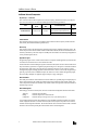
LONWORKS Network Components
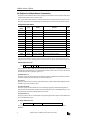
Physical Layer — Transceiver
The LONWORKS interface module incorporates an FTT-10A (Free Topology Twisted Pair Transceiver) for the physical
layer. The FTT-10A transceiver is a transformer-isolated type and has the following specifications:
Name
Communication
Media
Transmission
Rate
FTT-10A Transceiver
Twisted pair cable
78 kbps
Transmission Distance
Topology
500m (maximum total wire length)
400m (maximum node-to-node distance)
Free
1,150m
Bus
Note: The transmission distance is the value when Level 4 AWG22 cables and proper terminators are used.
LonTalk Protocol
The LonTalk protocol has all seven layers in compliance with the reference model of the Open System Interconnection
(OSI) issued by the International Standard Organization (ISO).
Neuron Chip
Some special LSI Neuron Chips that support the LonTalk protocol have firmware embedded in the built-in memory. The
Neuron Chip used in the LONWORKS interface module is Toshiba TMP3150B1AF, with firmware embedded in the external memory (flash memory). This Neuron Chip uses a 10MHz quartz clock oscillator. The Neuron Chip and peripheral circuit are powered through the CPU bus.
Application Program
The application program for the LONWORKS interface module is in compliance with the application layer of the OSI reference model, and is described in Neuron C that is derived from ANSI C.
Communication data is transferred through the registers located between the OpenNet Controller CPU bus and the Neuron
Chip external memory expansion bus. An application program including access to the registers is created and embedded in
the external memory (flash memory) along with firmware by IDEC before shipment. Users do not have to create and
install application programs, although programmers familiar with Neuron C can also create or modify the application program using a special tool, such as LonBuilder Developer’s Kit. When a user creates or modifies the application program,
the user must keep a backup file. For application program examples, see pages 18 through 22.
Network Variables
The LonTalk protocol allocates communication data to network variables (NV) specifically designed to simplify the procedures for packet transmission. The variables are available in input network variables and output network variables. The
values of output network variables are transmitted to input network variables of the target node on the network. Details are
described on pages 9 and 23.
Network Management
When setting up a LONWORKS network system, the user has to install network configuration information shown below.
Addressing:
Binding:
Configuration:
Determines each node address
Determines target nodes to communicate with
Determines the type of message service, retry cycles, timeout period, etc.
Use a network management tool from other manufacturers (such as LonMaker for Windows Integration Tool) to install
network configuration information. An external interface file (XIF extension) unique to each product series is needed to
install the network configuration information. The external interface file for the LONWORKS interface module is available
from IDEC. The user must keep a backup file of the information used for network management.
2
OPENNET CONTROLLER LONWORKS INTERFACE MODULE USER’S MANUAL
LONWORKS INTERFACE MODULE
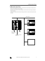
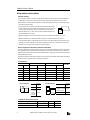
LONWORKS Network System Setup
Various LONWORKS compliant devices, such as the LONWORKS interface module and IDEC SX5L communication I/O
terminals, can be connected to the LONWORKS network.
The OpenNet Controller can be used as a node by adding the LONWORKS interface module to the right of the OpenNet
Controller CPU module.
A maximum of seven OpenNet interface modules and analog I/O modules can be mounted with one OpenNet Controller
CPU module.
LONWORKS Network
POWER
POW
RUN
ERR
I/O
SER
RUN
ERROR
HSC OUT
COM A
SERVICE
REQUEST
0
1
2
3
4
5
6
7
10
11
12
13
14
15
16
17
B
RS485
Z HSC
OUT A B G +24V 0V
IDEC SX5L Communication I/O Terminal
LON
idec
IDEC
OpenNet Controller
CPU Module
I/O Module
LONWORKS Interface Module
FC3A-SX5LS1
IDEC SX5L Communication I/O Terminal
Other LONWORKS Compliant Devices
OPENNET CONTROLLER LONWORKS INTERFACE MODULE USER’S MANUAL
3
LONWORKS INTERFACE MODULE
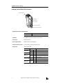
LONWORKS Interface Module Parts Description
Expansion Connector
(1) Module ID
(5) Status LED
(2) FG Terminal
SERVICE
REQUEST
LON
(3) Service Request Button
(4) Network Interface Connector
OpenNet Interface Module for LONWORKS Network
Module Name
LONWORKS Interface Module
Type No.
FC3A-SX5LS1
(1) Module ID
FC3A-SX5LS1 indicates the LONWORKS interface module ID.
(2) FG Terminal
Frame ground terminal
(3) Service Request Button
Pushbutton used for network management
(4) Network Interface Connector
For connecting the LONWORKS communication cable
(5) Status LED
Indicates operating status
Indicator
POW (POWER)
RUN
ERR
(COM_ERROR)
I/O (I/O_ERROR)
SER (SERVICE)
4
Status
Description
—
OFF
Module power OFF
Green
ON
Module power ON
Green
ON
Normal operation
—
OFF
Normal operation
Red
ON
Communication error
—
OFF
Normal operation
Red
Yellow
ON
Access error to the CPU through I/O bus
ON
Application program not configured
Flash
Network management not configured
OPENNET CONTROLLER LONWORKS INTERFACE MODULE USER’S MANUAL
LONWORKS INTERFACE MODULE
LONWORKS Interface Module Specifications
Normal Operating Conditions
Operating Ambient Temperature
0 to +55°C (no freezing)
Storage Temperature
–25 to +70°C (no freezing)
Operating Humidity
Level RH1 30 to 90% (no condensation)
Pollution Degree
2 (IEC 60664)
Corrosion Immunity
Free from corrosive gases
Altitude
Operation:
Transportation:
Vibration Resistance
10 to 57 Hz, amplitude 0.075 mm; 57 to 150 Hz, acceleration 9.8 m/sec2 (1G);
10 sweep cycles each in 3 axes (total 80 minutes) (IEC1131)
Shock Resistance
147 m/sec2 (15G), 11 msec, 3 shocks each in 3 axes (IEC1131)
0 to 2000m
0 to 3000m
Power Supply (supplied from the OpenNet Controller CPU module)
Dielectric Strength
Between power terminal on CPU module and FG: 500V AC, 1 minute
Insulation Resistance
Between power terminal on CPU module and FG: 10 MΩ (500V DC megger)
Current Draw
Approx. 30 mA
Grounding
Ground Terminal
M3 sems
Grounding Resistance
100Ω maximum
Grounding Wire
UL1015 AWG22, UL1007 AWG18
Weight
Weight
Approx. 180g
Communication Specifications
Communication System
LON® system
Transceiver
FTT-10A (Free Topology Twisted Pair Transceiver made by Echelon)
Transmission Rate
78 kbps
Transmission Distance
(when using Level 4 AWG22 cables)
Free topology:
Bus topology:
Maximum Nodes
32,385 nodes in a network
Network Interface Connector
In the module:
To the cable:
Network Cable
1-wire connection: 0.2 to 2.5 mm2, AWG24 to 14
2-wire connection: 0.2 to 1.5 mm2, AWG24 to 16
Total 500m (400m maximum between nodes)
1,150m (when using FTT-10A transceivers only)
MSTB2.5/2-GF-5.08 (made by Phoenix Contact)
FRONT-MSTB2.5/2-STF-5.08 (made by Phoenix Contact)
OPENNET CONTROLLER LONWORKS INTERFACE MODULE USER’S MANUAL
5
LONWORKS INTERFACE MODULE
Wiring LONWORKS Interface Module
Precautions for Wiring
• Use a twisted-pair cable to connect the LONWORKS interface module to the network. Do not run the network cable in
parallel with or near power lines, output lines, and motor lines. Keep the network cable away from noise sources.
• Power down the LONWORKS interface module before you start wiring. Make sure wiring is correct before powering up
the LONWORKS interface module.
• One or two cables can be connected to one terminal of the network interface connector. When connecting one cable, use AWG24 to AWG14 cables (core cross-section 0.2
to 2.5 mm2). When connecting two cables to one terminal, use the same cables of
AWG24 to AWG16 (0.2 to 1.5 mm2). Do not use cables of different diameters. Strip
the cable insulation as shown at right.
7 mm
• Tighten the mounting screws of the network interface connector to a recommended torque of 0.3 to 0.5 N·m.
• Tighten the terminal screws of the network interface connector to a recommended torque of 0.5 to 0.6 N·m.
• To prevent electrical shocks or communication error due to noises, connect the FG terminal to a proper ground using a
grounding wire of UL1015 AWG22 or UL1007 AWG18 (grounding resistance 100Ω maximum). Do not connect the
grounding wire in common with the grounding wire of motor equipment.
Ferrules, Crimping Tool, and Screwdriver for Phoenix Terminal Blocks
The screw terminal block of the network interface connector can be wired with or without using ferrules on the end of the
cable. Applicable ferrules for the terminal block and crimping tool for the ferrules are listed below. Use a screwdriver to
tighten the screw terminals on the LONWORKS interface module. Ferrules, crimping tool, and screwdriver are made by and
available from Phoenix Contact.
Type numbers of Phoenix Contact ferrules, crimping tool, and screwdriver are listed below. When ordering these products
from Phoenix Contact, specify the Order No. and quantity listed below.
• Ferrule Order No.
Applicable Wire Size
mm2
AWG
For 1-wire connection
Phoenix Type
Order No.
For 2-wire connection
Phoenix Type
Order No.
0.25
24
AI 0,25-8 YE
32 00 85 2
—
—
100
0.5
20
AI 0,5-8 WH
32 00 01 4
AI-TWIN 2 x 0,5-8 WH
32 00 93 3
100
0.75
18
AI 0,75-8 GY
32 00 51 9
AI-TWIN 2 x 0,75-8 GY
32 00 80 7
100
1.0
18
AI 1-8 RD
32 00 03 0
AI-TWIN 2 x 1-8 RD
32 00 81 0
100
1.5
16
AI 1,5-8 BK
32 00 04 3
AI-TWIN 2 x 1,5-8 BK
32 00 82 3
100
2.5
14
AI 2,5-8 BU
32 00 52 2
—
100
For 1-wire Connection
A
8.0 mm
Ferrule
Dimension
A
AI 0,25-8 YE
4.5 mm
AI
AI
AI
AI
AI
0,5-8 WH
0,75-8 GY
1-8 RD
1,5-8 BK
2,5-8 BU
6.0 mm
—
For 2-wire connection
B
8.0 mm
Ferrule
Dimension
B
AI-TWIN 2 x 0,5-8 WH
AI-TWIN 2 x 0,75-8 GY
AI-TWIN 2 x 1-8 RD
7.0 mm
AI-TWIN 2 x 1,5-8 BK
8.0 mm
• Crimping Tool and Screwdriver Order No.
Tool Name
6
Pcs./Pkt.
Phoenix Type
Order No.
Pcs./Pkt.
Crimping Tool
CRIMPFOX UD 6
12 04 43 6
1
Screwdriver
SZS 0,6 x 2,5
12 05 04 0
10
OPENNET CONTROLLER LONWORKS INTERFACE MODULE USER’S MANUAL
LONWORKS INTERFACE MODULE
Terminator
Terminators must be connected to the LONWORKS network. When setting up a network, connect one or two terminators
depending on the topology. The terminator consists of one resistor and two capacitors as illustrated below:
Terminator Configuration
C1 +
R
C2 +
Network
Bus Topology
Connect terminators to the both ends of the bus topology network.
R
105Ω, 1%, 1/8W
C1 and C2
100 µF, ≥50V (note the polarity)
Node
Node
Node
Terminator
Terminator
Node
Node
Node
Node
Free Topology
Connect a terminator to any position on the free topology network.
R
52.3Ω, 1%, 1/8W
C1 and C2
100 µF, ≥50V (note the polarity)
Node
Node
Terminator
Node
Node
Node
Node
Node
OPENNET CONTROLLER LONWORKS INTERFACE MODULE USER’S MANUAL
7
LONWORKS INTERFACE MODULE
Link Registers for LONWORKS Network Communication
LONWORKS network communication data is stored to link registers in the OpenNet Controller CPU module and the data is
communicated through the LONWORKS interface module.
Since seven functional modules, including a LONWORKS interface module, can be mounted with one OpenNet Controller
CPU module, link registers are allocated depending on the position where the LONWORKS interface module is mounted.
Link Register Allocation Numbers
Allocation
Number
Area
Function
L*00
Data area
Receive data
Stores received data from the network
Read
L*01
Data area
Receive data
Stores received data from the network
Read
L*02
Data area
Receive data
Stores received data from the network
Read
L*03
Data area
Receive data
Stores received data from the network
Read
L*04
Data area
Transmit data
Stores transmit data for the network
Write
L*05
Data area
Transmit data
Stores transmit data for the network
Write
L*06
Data area
Transmit data
Stores transmit data for the network
Write
L*07
Data area
Transmit data
Stores transmit data for the network
Write
L*12
Status area
Error data
Stores various error codes
Read
L*13
Status area
I/O counts
Stores the byte counts of transmit/receive data
Read
L*24
ID area
Software version
Stores the user application software version
Read
L*25
ID area
Expansion module ID
Stores the user program module ID
Read
Description
R/W
Note: A number 1 through 7 comes in place of * depending on the position where the functional module is mounted, such
as OpenNet interface module or analog I/O module. Consequently, operand numbers are automatically allocated to each
functional module in the order of increasing distance from the CPU module, starting with L100, L200, L300, through L700.
Error Data (Status Area) L*12
L*12
b15 b14: unused b13
b12
b11
b10-b0: unused
When an error occurs, the I/O or ERR LED on the LONWORKS interface module goes on, according to the error, and a corresponding bit in the link register goes on. The status LED goes off when the cause of the error is removed. The error data
bit remains on until the CPU is powered up again or reset.
b15 (initialization error)
This bit goes on when the CPU module fails to acknowledge the completion of initialization for communication with the
LONWORKS interface module. When this bit goes on, the I/O LED also goes on.
b13 (I/O error)
This bit goes on when an error occurs during communication with the LONWORKS interface module through the CPU bus.
When this bit goes on, the I/O LED also goes on.
b12 (transaction timeout)
This bit goes on when the CPU module fails to receive an acknowledge reply during communication through the LONWORKS network, with the acknowledge (ACKD) service enabled. When this bit goes on, the ERR LED also goes on. The
transaction timeout is enabled only when the ACKD service is selected.
b11 (transmission error)
This bit goes on when a CRC error is detected while receiving incoming data from the LONWORKS network. When this bit
goes on, the ERR LED also goes on.
I/O Counts (Status Area) L*13
L*13 b15-b12: transmit bytes
b11-b8: receive bytes
b7-b0: unused
This link register stores the transmit and receive byte counts selected in the Function Area Setting > Open Bus in
WindLDR™.
8
OPENNET CONTROLLER LONWORKS INTERFACE MODULE USER’S MANUAL
LONWORKS INTERFACE MODULE
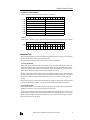
Link Registers and Network Variables
Network variables are allocated to data areas of the link registers as shown below.
b15
b14
b13
b12
b11
b10
b9
b8
b7
b6
b5
b4
b3
L*00
nv_i8[1]
nv_i8[0]
L*01
nv_i8[3]
nv_i8[2]
L*02
nv_i8[5]
nv_i8[4]
L*03
nv_i8[7]
nv_i8[6]
L*04
nv_o8[1]
nv_o8[0]
L*05
nv_o8[3]
nv_o8[2]
L*06
nv_o8[5]
nv_o8[4]
L*07
nv_o8[7]
nv_o8[6]
b2
b1
b0
• Example
Network variables nv_i8[0] and nv_i8[1] are allocated to link register data areas L100.00 through L100.15 as listed below.
nv_i8[1]
nv_i8[0]
L100 b15 b14 b13 b12 b11 b10
MSB
1
0
0
0
1
1
b9
b8
1
LSB MSB
1
0
b7
b6
1
b5
0
b4
0
b3
0
b2
1
b1
b0
1
LSB
1
Transmission Time
The transmission time depends on the network configuration, application program, and user program. It is recommended
that you confirm the transmission time on the actual network system.
Processing transmit and receive data to and from the LONWORKS network is described below:
• Processing Transmit Data
The data in link registers are updated each time the CPU module scans the user program. The LONWORKS interface module reads data from the link registers allocated to transmit data in the OpenNet Controller CPU module. When any changes
are found in the comparison between the new and old read data, the interface module updates the transmit network variables of which the data has been changed, and the new data is transmitted to the network.
The refresh cycle of reading from the link register to the interface module is approximately 15 msec. When the data in the
link register is changed within 15 msec, the preceding data is not transmitted to the interface module. Data communication
between the CPU module and the interface module through link registers is not in synchronism with the user program
scanning.
When the CPU is powered up, the transmit data in the link registers are cleared to 0. Consequently, 0 cannot be transmitted
in the first cycle immediately after the CPU is powered up because the transmit network variables are not updated.
• Processing Receive Data
When the interface module receives data from the network, corresponding receive network variables are updated, and the
updated data is stored to the receive data area of link registers in the CPU module.
The refresh cycle of reading from the interface module to the link register is also approximately 15 msec, and is not in synchronism with the user program scanning. When the interface module receives subsequent data within 15 msec, the incoming data is stored in the buffer and is transmitted to link registers every 15 msec. The data in the link register is read each
time the CPU module scans the user program.
OPENNET CONTROLLER LONWORKS INTERFACE MODULE USER’S MANUAL
9
LONWORKS INTERFACE MODULE
Function Area Setting for LONWORKS Node
The quantity of transmit/receive data for LONWORKS network communication is specified using the Function Area Setting
in WindLDR. The OpenNet Controller CPU module recognizes all functional modules, such as OpenNet interface modules
and analog I/O modules, automatically at power-up and exchanges data with LONWORKS nodes through the link registers
allocated to each node.
Since these settings relate to the user program, the user program must be downloaded to the OpenNet Controller after
changing any of these settings.
Programming WindLDR
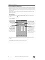
1. From the WindLDR menu bar, select Configure > Function Area Settings. The Function Area Setting dialog box
appears.
2. Select the Open Bus tab.
Configure Communication
Master Module Check Box
Check this box only when
the remote I/O master
module is used.
Quantity of Nodes Connected
When using the remote I/O master module, specify the quantity
of nodes from 1 through 32.
Slave Station
Transmit/Receive
Data Quantity (Bytes)
When using OpenNet interface modules for DeviceNet,
INTERBUS, or LONWORKS,
specify the data bytes to
communicate through each
OpenNet interface module.
Transmit/Receive Bytes 0 to 8
(default: 8 bytes)
This value determines the data
quantity 0 through 8 bytes (64
bits) to communicate with the
network.
For the example on the next
page, select 8 transmit bytes and
4 receive bytes for Module 1.
3. Select transmit and receive data bytes for module position 1 through 7 where the LONWORKS interface module is
mounted.
4. Click the OK button and download the user program to the OpenNet Controller.
10
OPENNET CONTROLLER LONWORKS INTERFACE MODULE USER’S MANUAL
LONWORKS INTERFACE MODULE
Programming Transmit/Receive Data Using WindLDR
The OpenNet interface module exchanges data between the open network and the link registers in the CPU module allocated to the OpenNet interface module, depending on the slot where the OpenNet interface module is mounted.
To create a communication program for an OpenNet interface module, first determine the slot number where the OpenNet
interface module is mounted, and make a program to write data to link registers allocated to transmit data and to read data
from link registers allocated to receive data.
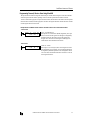
Example: When a LONWORKS interface module is mounted in the first slot of all functional modules
• Transmit Data
MOV(W)
I0
S1 –
65535
D1 R
L104
REP
4
S1 R
L100
D1 R
D0
REP
2
65535 → L104 through L107
When input I0 is on, constant 65535 (FFFFh) designated by source operand S1 is moved to four link registers L104 through L107 designated by
destination operand D1. All 64 bits (8 bytes) in link registers L104
through L107 are turned on. Since link registers L104 through L107
transmit data, the data is transmitted to the network.
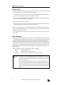
• Receive Data
MOV(W)
I1
L100·L101 → D0·D1
When input I1 is on, 32-bit (4-byte) data in two link registers L100 and
L101 designated by source operand S1 is moved to data registers D0 and
D1 designated by destination operand D1. Since link registers L100 and
L101 receive data, communication data read to L100 and L101 is moved
to data registers D0 and D1.
OPENNET CONTROLLER LONWORKS INTERFACE MODULE USER’S MANUAL
11
LONWORKS INTERFACE MODULE
Starting Operation
The LONWORKS network requires installation of network configuration information into each node. When setting up the
LONWORKS network for the first time, follow the procedures described below:
1. Set up the OpenNet Controller CPU and LONWORKS interface modules, connect the LONWORKS interface module to
the LONWORKS network using LONWORKS cables, and power up the CPU module.
2. Connect a network management tool to the network and install network configuration information to the LONWORKS
interface module. See Network Management described below.
3. Download the user program to the CPU module.
4. Start the CPU module to run, then the CPU module starts to communicate with other nodes on the LONWORKS network as specified in the network configuration information and user program.
The delay until the communication starts after power-up depends on the size of the user program and the system setup.
While the CPU is stopped, data exchange between the CPU and LONWORKS interface modules is halted, but communication with the LONWORKS network continues.
Data exchange between the CPU and LONWORKS interface modules is asynchronous with the user program scanning in
the CPU module.
Network Management
When setting up a LONWORKS network system, the user has to install network configuration information into each node.
Use a network management tool available from other manufacturers (such as LonMaker for Windows Integration Tool) to
install network configuration information. An external interface file (XIF extension) unique to each product series is
needed to install the network configuration information. The external interface file for the LONWORKS interface module is
available from IDEC. Find an XIF No. printed on the side of the LONWORKS interface module or on the shipping package.
When requesting an external interface file, inform IDEC of the XIF No. that represents the external interface file version
number. Without a correct external interface file of the matching XIF No., network configuration information cannot be
installed successfully.
The network configuration information includes addressing, binding, and configuration.
Addressing:
Binding:
Configuration:
Determines each node address
Determines target nodes to communicate with
Determines the type of message service, retry cycles, timeout period, etc.
Caution • When using the LONWORKS interface module, select the acknowledge (ACKD) service to enable
the message service for network variables and set the retry cycles to a value of 1 or more. If communication is performed using other than the ACKD service, the ERR LED on the interface module does not function properly.
• When installing the network configuration information without modifying the application program, an external interface file (XIF extension) containing information, such as the network variables of the LONWORKS interface module, is needed. Consult IDEC for the external interface file.
• The user must keep a backup file of the network configuration information used for network management.
12
OPENNET CONTROLLER LONWORKS INTERFACE MODULE USER’S MANUAL
LONWORKS INTERFACE MODULE
Precautions for Modifying Application Program
The LONWORKS interface module is shipped with a standard application program installed. Users with expertise in programming can also modify or create application programs using a special programming tool, such as LonBuilder Developer’s Kit. The application program is written in Neuron C. Read this section before starting modifications.
Define Neuron Chip I/O pins
As shown in the sample program on page 19, define I/O pins IO.0 through IO.4 and IO.6 of the Neuron Chip. If these pins
are not defined correctly, the LONWORKS interface module may be damaged. For the description of I/O pins, see page 15.
Include necessary codes in the application program
When you modify or create an application program, make sure that the codes shown in italics in the application program
examples on pages 18 through 22 are included in the application program.
Defined network variables
The application program installed in the LONWORKS interface module defines network variables for transmit and receive
data listed on page 23. When you modify or create an application program, do not use these variable names, otherwise verification of the application program will be difficult.
Precautions for writing and reading registers
Make a program to write and read data to and from registers in the LONWORKS interface module as shown in the sample
programs on pages 21 and 22.
While data write or read is in progress, do not execute any other command.
Precautions for downloading an application program to the flash memory through the network
A special tool is required to download an application program. Before starting download, stop the OpenNet Controller
CPU operation. While downloading is in progress, make sure the power voltage is within the rated operating voltage
range.
Precautions for flash memory used for the application program
Do not store variables to the flash memory. To hold variables and other data while power is off, use the RAM backup function of the CPU module.
The flash memory can be rewritten a maximum of 10,000 times.
Precautions for system setup
Set the retry cycles of the message service to a value of 1 or more.
OPENNET CONTROLLER LONWORKS INTERFACE MODULE USER’S MANUAL
13
LONWORKS INTERFACE MODULE
LONWORKS Interface Module Internal Structure
The LONWORKS interface module block diagram is illustrated in the figure below:
Status LED
Service Request Button
Register
Link Register
Flash
Memory
SER
LED
RUN
LED
ERR
LED
I/O
LED
SERVICE
IO.0 IO.1 IO.2
Transceiver
FTT-10A
Neuron Chip 3150
IO.6
Failure
IO.4
RUN
CPU Module
LONWORKS Interface Module
LONWORKS
Network
Memory Map
The LONWORKS interface module memory map is illustrated in the figure below:
FFFFh
Reserved for Memory
Map I/O (1KB)
Neuron Chip 3150 (6KB)
E800h
FFFFh
FC00h
Unused
CFFFh
Register (4KB)
Reserved (2.5KB)
Unused
EEPROM (0.5KB)
C000h
F1FFh
F000h
7FFFh
Flash
Memory
(32KB)
RAM (2KB)
Application
Program
(16KB)
4000h
3FFFh
E800h
Neuron Chip
Firmware
(16KB)
0000h
Flash Memory
The LONWORKS interface module contains a 32KB nonvolatile rewritable memory. Of the 32KB memory area, a 16KB
area of 0000h through 3FFFh is allocated to the Neuron Chip firmware, and the remaining 16KB area of 4000h through
7FFFh is allocated to the application program.
14
OPENNET CONTROLLER LONWORKS INTERFACE MODULE USER’S MANUAL
LONWORKS INTERFACE MODULE
Neuron Chip I/O Pins and Status LEDs
Neuron Chip I/O pins and status LEDs are assigned as listed below:
I/O Pin No.
I/O
Signal Name
0
Output
RUN LED
Controls the RUN LED (green).
0: ON, 1: OFF
1
Output
ERR LED
Controls the ERR LED (red).
0: ON, 1: OFF
2
Output
I/O LED
Controls the I/O LED (red).
0: ON, 1: OFF
3
Input
—
4
Input
RUN
5
—
unused
6
Output
Failure
7-10
—
unused
Description
The IO.3 pin must be defied as an input when the application program is
modified by the user. See page 19.
Monitors the CPU module operating status.
0: CPU stopped, 1: CPU in operation
Error signal to the CPU
0: The Neuron Chip cannot write data to registers. When modifying the application program, make sure to turn this pin to 0 when an unrecoverable
critical error occurs.
1: Normal operation
Registers
The OpenNet Controller CPU module exchanges communication data through the registers in the LONWORKS interface
module. The register addresses are listed in the table below:
Data Flow Direction
Address
Name
CPU
Module
Description
Interface
Module
C000h - C007h
Data register
(8 bytes)
C008h - C00Fh
Data register
(8 bytes)
C010h - C011h
reserved
C012h
Error data
Use this address to read error data from the
interface module.
C013h
I/O counts
Use this address to store the byte counts of
transmit/receive data selected in WindLDR
Function Area Settings.
C014h - C017h
reserved
Allocate network variables to these
addresses to exchange data between the
CPU and interface modules.
—
—
—
—
Do not write data into this area.
Do not write data into this area.
C018h
Software version
Use this address to write the user application software version number (use any number other than 00h).
C019h
Expansion module ID
Use this address to write the user program
module ID (use a number 40h through 7Fh).
C01Ah - CFFFh
reserved
—
—
Do not write data into this area.
OPENNET CONTROLLER LONWORKS INTERFACE MODULE USER’S MANUAL
15
LONWORKS INTERFACE MODULE
Data Exchange between LONWORKS Interface Module and CPU Module
Communication data, status data, and ID data are exchanged through registers in the LONWORKS interface module and
link registers in the CPU module. The registers correspond to link registers as listed below:
Register Address in
LONWORKS Interface Module
Link Register in CPU Module
C000h - C001h
L*00
C002h - C003h
L*01
C004h - C005h
L*02
C006h - C007h
L*03
C008h - C009h
L*04
Function
Area
Receive Data
Communication
Data Area
C00Ah - C00Bh
L*05
C00Ch - C00Dh
L*06
C00Eh - C00Fh
L*07
C012h
L*12
Error Data
C013h
L*13
I/O Counts
C018h
L*24
Software Version
C019h
L*25
Expansion Module ID
Transmit Data
Status Area
ID Area
Note: A number 1 through 7 comes in place of * depending on the position where the functional module, such as OpenNet
interface module or analog I/O module, is mounted. Consequently, operand numbers are automatically allocated to each
functional module in the order of increasing distance from the CPU module, starting with L100, L200, L300, through L700.
Example 1: Receive Data in Registers C000h and C001h
When receive data enters registers C000h and C001h in the LONWORKS interface module, the data is transferred to a link
register in the CPU module as illustrated below:
C001h (8 bits)
Registers in the
LONWORKS Interface Module
Link Register L*00
in the CPU Module
b7
b6
b5
b4
b3
C000h (8 bits)
b2
b1
b0
b7
0
0
0
0
b6
b5
b4
b3
MSB
0
0
0
0
0
0
1
LSB MSB
0
0
b15
b14
b13
b12
b11
b10
b9
b8
MSB
0
0
0
0
0
0
1
0
b7
0
b6
0
b5
0
b4
0
b3
0
b2
b1
b0
0
0
LSB
1
b2
b1
b0
0
LSB
1
0
Example 2: Transmit Data in Link Register L*04
When transmit data is stored to link register L*04 in the CPU module, the data is transferred to registers in the LONWORKS
interface module as illustrated below:
b15
Link Register L*04
in the CPU Module
b14
b13
b12
MSB
0
1
1
b7
b6
b5
b4
MSB
0
1
1
0
0
b11
0
b10
b9
b8
b7
b6
b5
16
0
b3
0
b2
b1
b0
0
0
LSB
0
0
0
0
0
0
1
b3
b2
b1
b0
b7
b6
b5
b4
b3
b2
b1
b0
0
0
0
LSB MSB
0
0
0
1
0
0
0
0
LSB
0
C009h (8 bits)
Registers in the
LONWORKS Interface Module
b4
C008h (8 bits)
OPENNET CONTROLLER LONWORKS INTERFACE MODULE USER’S MANUAL
LONWORKS INTERFACE MODULE
Example 3: Error Data in Register C012h
When error data enters register C012h in the LONWORKS interface module, the data is transferred to a link register in the
CPU module as illustrated below:
C012h (8 bits)
Register in the
LONWORKS Interface Module
Link Register L*12
in the CPU Module
b7
b6
b5
b4
b3
MSB
1
0
0
0
0
b15
b14
b13
b12
b11
MSB
1
0
0
0
0
b2
b1
b0
0
1
LSB
0
b10
b9
b8
0
1
0
b7
0
b6
0
b5
0
b4
0
b3
0
b2
0
b1
b0
0
LSB
0
Example 4: I/O Counts in Link Register L*13
When 8 bytes (output) and 4 bytes (input) are selected as the transmit and receive data quantities in WindLDR Function
Area Settings, respectively, these values are stored to link register L*13 in the CPU module, and the data is transferred to
register C013h in the LONWORKS interface module as illustrated below:
Link Register L*13
in the CPU Module
b15
b14
b13
b12
b11
b10
b9
b8
b7
b6
b5
b4
b3
b2
b1
b0
MSB
1
0
0
0
0
1
0
0
0
0
0
0
0
0
0
LSB
0
C013h (8 bits)
Register in the
LONWORKS Interface Module
Transmit Byte Count (8)
Receive Byte Count (4)
b7
b6
b5
b4
b3
b2
b1
b0
MSB
1
0
0
0
0
1
0
LSB
0
Note: Link register L*13 is for read only. Do not write data into L*13.
Example 5: Software Version in Register C018h and Expansion Module ID in Register C019h
When a software version number is stored to register C018h in the LONWORKS interface module, or when an expansion
module ID is stored to register C019h in the LONWORKS interface module, the data is transferred to a link register in the
CPU module as illustrated below:
C018h or C019h (8 bits)
Register in the
LONWORKS Interface Module
Link Register L*24 or L*25
in the CPU Module
b7
b6
b5
b4
b3
MSB
0
1
0
0
0
b15
b14
b13
b12
b11
MSB
0
1
0
0
0
b2
b1
b0
0
0
LSB
0
b10
b9
b8
0
0
0
b7
0
b6
0
b5
0
OPENNET CONTROLLER LONWORKS INTERFACE MODULE USER’S MANUAL
b4
0
b3
0
b2
0
b1
b0
0
LSB
0
17
LONWORKS INTERFACE MODULE
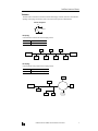
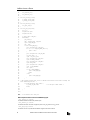
Application Program Examples
This section describes application program examples for initializing the registers in the LONWORKS interface module,
writing receive data to data registers, and reading transmit data from data registers.
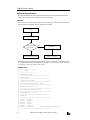
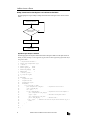
Initialization
Before starting LONWORKS communication through the network, the data registers in the LONWORKS interface module
have to be initialized. The initialization sequence is illustrated in the chart below:
Power up
when(reset) Initialization
Is the register initialization complete?
NO
I/O LED goes on.
YES
Start to execute a user program.
Initialization is not complete.
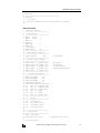
The following program is an example of an application program in Neuron C to initialize the LONWORKS interface module, consisting of initialization codes and a header file. When you modify or create an application program, make sure that
the application program includes the following codes in italics.
Initialization Codes
1.
2.
3.
4.
5.
6.
7.
8.
9.
10.
11.
12.
13.
14.
15.
16.
17.
18.
19.
20.
21.
22.
23.
24.
25.
26.
18
///////////////////////////////
///
PRAGMA
///
///////////////////////////////
#pragma scheduler_reset
/********************************************************
Network Variable
********************************************************/
/* Define network variables
*/
/********************************************************
Write the software version number to C018h
*********************************************************/
#define FC3ASX5L_VERSION
0x10
/********************************************************
Write the expansion module ID to C019h
*********************************************************/
#define EMID_CODE
0x50
/********************************************************
include file
*********************************************************/
#include
<access.h>
#include
<msg_addr.h>
#include
<control.h>
#include
<status.h>
#include
<snvt_lev.h>
#include
“fc3asx5l.h”
/* Refer to the header file shown below */
/********************************************************
OPENNET CONTROLLER LONWORKS INTERFACE MODULE USER’S MANUAL
LONWORKS INTERFACE MODULE
27.
28.
29.
30.
31.
32.
Main Program
*********************************************************/
when(reset){
initialize();
/* Insert other commands here to execute within when(reset), if required. */
}
Header File (fc3asx5l.h)
1.
2.
3.
4.
5.
6.
7.
8.
9.
10.
11.
12.
13.
14.
15.
16.
17.
18.
19.
20.
21.
22.
23.
24.
25.
26.
27.
28.
29.
30.
31.
32.
33.
34.
35.
36.
37.
38.
39.
40.
41.
42.
43.
44.
45.
46.
47.
48.
49.
50.
51.
52.
53.
//Header File: fc3asx5l.h
/*************************************/
/* Common Definition
*/
/*************************************/
#define
LED_OFF
1
#define
LED_ON
0
#define OK
1
#define NG
0
#define HIGH
1
#define LOW
0
/* Timer Value */
#define DTm_5sec
5000
/*************************************/
/* Memory Mapped I/O Definition
*/
/*************************************/
#define IO_GA_BASE
0xc000
//
/*************************************/
/* Digital I/O Register Address
*/
/*************************************/
#define GA_FCDR
(IO_GA_BASE + 0x00)
//
#define GA_CSR_ERR (IO_GA_BASE + 0x12)
//
#define GA_FVER
(IO_GA_BASE + 0x18)
//
#define GA_EMID
(IO_GA_BASE + 0x19)
//
#define GA_BCTL
(IO_GA_BASE + 0x1a)
/*************************************/
/* I/O Register Bit Definition
*/
/*************************************/
#define BCTL_CENABLE
0x10
#define BCTL_NWR_REQ
0x04
#define BCTL_NENABLE
0x01
#define MAX_FCDR_DATA_LEN
16
/* Define Neuron Chip IO pins as follows. */
IO_0
output bit PO_RUN_LED = HIGH;
IO_1
output bit PO_ERR_LED = HIGH;
IO_2
output bit PO_IO_LED = HIGH;
IO_3
input
bit PI_ODE;
IO_4
input
bit PI_RUN;
IO_6
output bit PO_F_ERR = LOW;
/*************************************/
/*
Prototype
*/
/*************************************/
void
initialize(void);
void
init_internal_io(void);
void
init_external_io(void);
void
init_gate_array(void);
I/O Base Address
Data Register
Error Register
I/O Version Register
Expansion Module ID Register
/*************************************/
/*
Global Variable
*/
/*************************************/
mtimer io_check_timer;
unsigned char csr_error_data;
// CSR_ERROR Reg. data save area
void initialize(void){
OPENNET CONTROLLER LONWORKS INTERFACE MODULE USER’S MANUAL
19
LONWORKS INTERFACE MODULE
54.
55.
56.
57.
58.
59.
60.
61.
62.
63.
64.
65.
66.
67.
68.
69.
70.
71.
72.
73.
74.
75.
76.
77.
78.
79.
80.
81.
82.
83.
84.
85.
86.
87.
88.
89.
90.
91.
92.
93.
94.
95.
96.
97.
init_internal_io();
init_external_io();
}
void init_internal_io(void){
io_change_init(PI_ODE);
io_change_init(PI_RUN);
}
void init_external_io(void){
init_gate_array();
}
void init_gate_array(void){
int st, n;
unsigned char *pGA;
unsigned char dat;
io_check_timer = DTm_5sec;
while(TRUE){
post_events();
pGA = (unsigned char *)GA_BCTL;
*pGA |= BCTL_NWR_REQ;
dat = *pGA;
if (dat & BCTL_NWR_REQ){
pGA = (unsigned char *)GA_FCDR;
for (n = 0; n < MAX_FCDR_DATA_LEN; n++){
*pGA++ = 0x00;
}
pGA = (unsigned char *)GA_CSR_ERR;
csr_error_data = 0;
*pGA = csr_error_data;
pGA = (unsigned char *)GA_FVER;
*pGA = FC3ASX5L_VERSION;
pGA = (unsigned char *)GA_EMID;
*pGA = EMID_CODE;
pGA = (unsigned char *)GA_BCTL;
*pGA |= BCTL_NENABLE;
dat = *pGA;
if (dat & BCTL_NENABLE){
*pGA &= ~BCTL_NWR_REQ;
break;
}else{
*pGA &= ~BCTL_NWR_REQ;
}
}
/* The following program turns on the I/O LED when initialization fails within 5 seconds, and
can be modified by the user. */
98.
if (timer_expires(io_check_timer)){
99.
io_out(PO_IO_LED, LOW);
/* I/O LED goes on when timeout */
100.
break;
101.
}
102.
}
103.}
Note: ~ is an exclusive OR of every bit.
Brief description of functions used for the initialization program
• init_internal_io() function
This function initializes the Neuron Chip internal IO pins.
• init_external_io() function
This function substitutes the number of register IO points for max_out_number or max_in_number.
• init_gate_array() function
This function turns on the I/O LED when initialization of registers fails within 5 seconds.
20
OPENNET CONTROLLER LONWORKS INTERFACE MODULE USER’S MANUAL
LONWORKS INTERFACE MODULE
Writing Receive Data to Data Registers in the LONWORKS Interface Module
The following diagram shows a typical example of writing receive data to the data registers in the LONWORKS interface
module.
Preparation for data write
Is preparation for data
write complete?
NO
YES
Write data
End data write
Application Program Example for Data Write
The following program is an example to write receive data to data register C000h of the LONWORKS interface module
when an 8-bit input network variable (nv_i8) is updated. When you modify or create an application program, make sure
that the application program includes the following codes in italics.
1.
2.
3.
4.
5.
6.
7.
8.
9.
10.
11.
12.
13.
14.
15.
16.
17.
18.
19.
20.
21.
22.
23.
/* Input Network Variables */
network input unsigned char nv_i8;
/* define */
#define GA_BCTL
0xC01A
#define BCTL_NWR_REQ
0x04
#define GA_FCDR_RX
0xC000
when(nv_update_occurs(nv_i8)){
/*
unsigned char *pGA;
unsigned char dat;
while(TRUE){
pGA = (unsigned char *)GA_BCTL;
/*
*pGA |= BCTL_NWR_REQ;
dat = *pGA;
if (dat & BCTL_NWR_REQ){
/*
pGA = (unsigned char *)GA_FCDR_RX;
pGA = nv_i8;
/*
pGA = (unsigned char *)GA_BCTL;
pGA &= ~BCTL_NWR_REQ;
/*
break;
}
}
}
Acknowledge input network variable update */
Preparation for data write */
Preparation for data write complete */
Write input NV data to data register C000h */
End data write */
OPENNET CONTROLLER LONWORKS INTERFACE MODULE USER’S MANUAL
21
LONWORKS INTERFACE MODULE
Reading Transmit Data from Data Registers in the LONWORKS Interface Module
The following diagram is a typical example of reading transmit data from the data registers in the LONWORKS interface
module.
Preparation for data read
Is preparation for data
read complete?
NO
YES
Read data
End data read
Application Program Example for Data Read
The following program is an example to substitute transmit data of data register C008h for an 8-bit output network variable (nv_o8). When you modify or create an application program, make sure that the application program includes the following codes in italics.
1.
2.
3.
4.
5.
6.
7.
8.
9.
10.
11.
12.
13.
14.
15.
16.
17.
18.
19.
20.
21.
22.
23.
24.
25.
26.
27.
28.
29.
30.
22
/* Output Network Variables */
network output unsigned char nv_o8;
/* define */
#define GA_BCTL
0xC01A
#define GA_FCDR_TX
0xC008
#define BCTL_NWR_REQ
0x04
#define HIGH
1
/* Define IO_4 RUN */
IO_4 input bit PI_RUN;
when(TRUE){
unsigned char *pGA;
unsigned char dat;
unsigned char tx_dat;
while(TRUE){
if (io_in(PI_RUN) == HIGH){
pGA = (unsigned char *)GA_BCTL;
/* Preparation for data read */
*pGA |= BCTL_NWR_REQ;
dat = *pGA;
if (dat & BCTL_NWR_REQ){
/* Preparation for data read complete */
pGA = (unsigned char *)GA_FCDR_TX;
tx_dat = *pGA;
/* Read data from register C008h */
pGA = (unsigned char *)GA_BCTL;
pGA &= ~BCTL_NWR_REQ;
/* End data read */
nv_o8 = tx_dat;
/* Substitute the value for output network variable (nv_o8) */
break;
}
}
}
}
OPENNET CONTROLLER LONWORKS INTERFACE MODULE USER’S MANUAL
LONWORKS INTERFACE MODULE
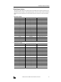
Defined Network Variables
The application program installed in the LONWORKS interface module defines network variables for transmit and receive
data listed below. When you modify or create an application program, do not use these variables, otherwise verification of
the application program will be difficult. The network variables, their data type and structure are listed in the following
tables.
Input Network Variables
Input Network Variable
Data Type and Structure
Used For
nv_i8[0]
unsigned char
8-point inputs, 8 bits
nv_i8[1]
unsigned char
8-point inputs, 8 bits
nv_i8[2]
unsigned char
8-point inputs, 8 bits
nv_i8[3]
unsigned char
8-point inputs, 8 bits
nv_i8[4]
unsigned char
8-point inputs, 8 bits
nv_i8[5]
unsigned char
8-point inputs, 8 bits
nv_i8[6]
unsigned char
8-point inputs, 8 bits
nv_i8[7]
unsigned char
8-point inputs, 8 bits
nv_i16
BIT16_DAT
16-point inputs, 8 bits × 2
nv_i24
BIT24_DAT
24-point inputs, 8 bits × 3
nv_i32
BIT32_DAT
32-point inputs, 8 bits × 4
nv_i40
BIT40_DAT
40-point inputs, 8 bits × 5
nv_i48
BIT48_DAT
48-point inputs, 8 bits × 6
nv_i56
BIT56_DAT
56-point inputs, 8 bits × 7
nv_i64
BIT64_DAT
64-point inputs, 8 bits × 8
Output Network Variable
Data Type and Structure
Used For
nv_o8[0]
unsigned char
8-point outputs, 8 bits
nv_o8[1]
unsigned char
8-point outputs, 8 bits
nv_o8[2]
unsigned char
8-point outputs, 8 bits
nv_o8[3]
unsigned char
8-point outputs, 8 bits
nv_o8[4]
unsigned char
8-point outputs, 8 bits
nv_o8[5]
unsigned char
8-point outputs, 8 bits
nv_o8[6]
unsigned char
8-point outputs, 8 bits
nv_o8[7]
unsigned char
8-point outputs, 8 bits
nv_o16
BIT16_DAT
16-point outputs, 8 bits × 2
nv_o24
BIT24_DAT
24-point outputs, 8 bits × 3
nv_o32
BIT32_DAT
32-point outputs, 8 bits × 4
nv_o40
BIT40_DAT
40-point outputs, 8 bits × 5
nv_o48
BIT48_DAT
48-point outputs, 8 bits × 6
nv_o56
BIT56_DAT
56-point outputs, 8 bits × 7
nv_o64
BIT64_DAT
64-point outputs, 8 bits × 8
Output Network Variables
OPENNET CONTROLLER LONWORKS INTERFACE MODULE USER’S MANUAL
23
LONWORKS INTERFACE MODULE
Structure Name
Structure
Used For
BIT16_DAT
typedef struct {
unsigned char dat[2];
}BIT16_DAT
16-point outputs, 8 bits × 2
BIT24_DAT
typedef struct {
unsigned char dat[3];
}BIT24_DAT
24-point outputs, 8 bits × 3
BIT32_DAT
typedef struct {
unsigned char dat[4];
}BIT32_DAT
32-point outputs, 8 bits × 4
BIT40_DAT
typedef struct {
unsigned char dat[5];
}BIT40_DAT
40-point outputs, 8 bits × 5
BIT48_DAT
typedef struct {
unsigned char dat[6];
}BIT48_DAT
48-point outputs, 8 bits × 6
BIT56_DAT
typedef struct {
unsigned char dat[7];
}BIT56_DAT
56-point outputs, 8 bits × 7
BIT64_DAT
typedef struct {
unsigned char dat[8];
}BIT64_DAT
64-point outputs, 8 bits × 8
Example:
When the transmit and receive bytes are set to 3 using WindLDR (on the Open Bus page selected from Configure > Function Area Settings), only 24-point type declared network variables (nv_i24 and nv_o24) and the network variables shown
in the table below can be used. Then, link registers listed below can be used for transmission and receiving.
b15
24
b14
b13
b12
b11
b10
b9
b8
b7
b6
b5
b4
b3
L*00
nv_i8[1]
L*01
cannot be used
nv_i8[2]
L*04
nv_o8[1]
nv_o8[0]
L*05
cannot be used
nv_o8[2]
b2
nv_i8[0]
OPENNET CONTROLLER LONWORKS INTERFACE MODULE USER’S MANUAL
b1
b0
LONWORKS INTERFACE MODULE
LONWORKS Network Troubleshooting
This section describes the procedures to determine the cause of trouble and actions to be taken when any trouble occurs
while operating the LONWORKS interface module.
Probable Causes for Network Errors
• A network cable is disconnected or shorted.
• Strong external noise
• The power voltage to the module has dropped below the minimum operating voltage at least momentarily.
• Use of a faulty communication line, cable other than twisted-pair cables, or transmission beyond the rated distance.
• Improper terminator
Troubleshooting Diagram 1
The POW LED on the LONWORKS
interface module does not go on.
Is the POWER LED on
the CPU module on?
NO
Supply power to the power supply
terminals on the CPU module.
YES
Is the POWER LED on
the CPU module on?
YES
NO
Are modules installed
correctly?
NO
Is the POW LED on the
interface module on?
NO
See Troubleshooting in the
OpenNet Controller user’s
manual EM333.
YES
Install the modules correctly.
YES
NO
Is the POW LED on the
interface module on?
YES
Call IDEC for assistance.
OPENNET CONTROLLER LONWORKS INTERFACE MODULE USER’S MANUAL
END
25
LONWORKS INTERFACE MODULE
Troubleshooting Diagram 2
The RUN LED on the LONWORKS
interface module does not go on.
Is the POW LED on the
interface module on?
Supply power to the power supply
terminals on the CPU module.
See Troubleshooting Diagram 1,
“The POW LED on the inter face
module does not go on.”
NO
YES
NO
Is the POW LED on the
interface module on?
YES
NO
Is the RUN LED on the
interface module on?
YES
Call IDEC for assistance.
26
END
OPENNET CONTROLLER LONWORKS INTERFACE MODULE USER’S MANUAL
LONWORKS INTERFACE MODULE
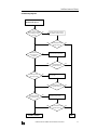
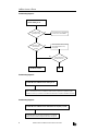
Troubleshooting Diagram 3
The ERR LED on the LONWORKS
interface module goes on.
Is the
interface module connected
to the LONWORKS network
correctly?
NO
Connect the inter face module to
the LONWORKS network correctly.
YES
YES
Is installation of the
network information
completed?
NO
Is the ERR LED on the
interface module on?
NO
Install the network information.
YES
YES
Is the target node
operating normally?
NO
Is the ERR LED on the
interface module on?
NO
Make sure the target node operates normally.
YES
YES
Is the network affected
by surrounding noise?
NO
Is the ERR LED on the
interface module on?
NO
Remove the noise source.
YES
YES
Is the ERR LED on the
interface module on?
Call IDEC for assistance.
OPENNET CONTROLLER LONWORKS INTERFACE MODULE USER’S MANUAL
NO
END
27
LONWORKS INTERFACE MODULE
Troubleshooting Diagram 4
The I/O LED on the LONWORKS
interface module goes on.
Is the CPU module
operating normally?
NO
See Troubleshooting in the OpenNet
Controller user’s manual EM333.
NO
Set the quantity of transmit/receive
data using WindLDR correctly.
See page 10.
YES
Is the transmit/receive
data quantity set
correctly?
YES
YES
Is the I/O LED on the
interface module on?
NO
Call IDEC for assistance.
END
Troubleshooting Diagram 5
The SER LED on the LONWORKS interface module goes on.
The SER LED goes on when the Neuron Chip fails to recognize an application program, no application program
exists, or an on-chip failure occurs. The LONWORKS inter face module is shipped with an application program
installed in the memor y, so a problem in the LONWORKS inter face module is suspected. Call IDEC for assistance.
Troubleshooting Diagram 6
The SER LED on the LONWORKS interface module flashes at a frequency of 1/2 Hz.
The SER LED flashes when the network management is not configured.
Configure (install) the network management information. See page 12.
28
OPENNET CONTROLLER LONWORKS INTERFACE MODULE USER’S MANUAL
INDEX
A
ACKD 12
acknowledge service 12
application program 2
examples 18
modifying 13
B
bus topology 7
C
communication terminals SX5L 3
crimping tool 6
D
data
type 23
defined network variables 23
E
error data 17
expansion module ID 17
external interface file 2, 12
F
ferrule 6
flash memory 14
free topology 7
function area setting LonWorks node 10
H
header file 19
I
I/O counts 17
I/O pins 13, 15
initialization 18
codes 18
input network variables 23
internal structure LonWorks interface module 14
International Standard Organization 2
ISO 2
L
link registers for LonWorks network communication 8
LON 1
LonMaker 2, 12
LonTalk protocol 2
LonWorks 1
network system setup 3
M
memory map 14
message service 13
modifying application program 13
N
network
configuration information 2
management 2, 12
variables 2, 9, 23
Neuron chip 2
I/O pins 13, 15
NV 2
O
open system interconnection 2
opennet interface module 1, 4
OSI 2
output network variables 23
P
programming transmit/receive data using WindLDR 11
R
reading transmit data 22
receive data 11, 16
writing 21
registers 15
S
screwdriver 6
software version 17
specifications LonWorks interface module 5
starting operation 12
status LEDs 15
structure 23
SX5L communication terminals 3
system setup LonWorks network 3
T
terminator 7
transceiver 2
transmission time 9
transmit data 11, 16
reading 22
troubleshooting LonWorks network 25
W
WindLDR programming transmit/receive data 11
wiring LonWorks interface module 6
writing receive data 21
X
XIF 2, 12
No. 12
OPENNET CONTROLLER LONWORKS INTERFACE MODULE USER’S MANUAL
29