1
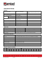
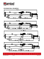
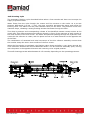
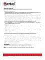
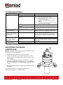
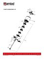
AMIAD Automatic Filters Filtomat M100-6800 Series Models: M104XLP, M106XLP, M108LP, M110P Hydraulically-Controlled Serial number: Order number: Catalog number: Filtration degree: Tested by: Installation, Operation and Maintenance Instructions October 2009 Ref. 95-046-610-403/10.2009 Amiad Automatic Filters M100-6800 Series Models: M104XLP, M106XLP, M108LP, M110P HydraulicallyControlled This document is the user-manual of the Filtomat M100 Hydraulically Controlled Series and it describes the installation, the operation and the maintenance procedures of the filters. isclaimer: This document and the information enclosed within it contain restricted and/or privileged information that are intended only for usage by authorized Amiad technicians. If you are not a qualified Amiad technician you must not take nay action in reliance to this do cument, unless permitted by Amiad. None of the procedures provided on this file may be used in any form or by any means without permission from Amiad. If you received this file in error please notify Amiad immediately. ([email protected]) The confidential nature of and/or privilege in the file enclosed is not waived or lost as a result of a mistake or error in this file. Amiad accepts no liability whatsoever, whether it was caused by: 1. Accessing or other related actions to this file. 2. Any links, procedures or materials provided/attached to this file. Amiad assumes that all users understand risks involved within this file and/or its attached materials. All the procedures, drawings, pictures and/or any other information provided in this document are presented as general information only; they can be altered, removed or changed without any further notice by Amiad. This document does not replace any certified drawing, procedure or information provided by Amiad in reference to a specific customer, site or project. All rights reserved. Ref. 95-046-610-403/10.2009 Filtomat M100-6800 10.2009 Page 2 of 24 TABLE OF CONTENTS Specifications ……………………………………………………………………………………………………………… 4 Safety instructions ……………………………………………………………………………………………………. 5 Dimensional drawing ………………………………………………..………………………………………………. 6 Introduction ……………………………………………………………………………………………………………….. 7 Installation ………………………………………………………………………………………………………………….. 9 Preparations for installation ………………………………………………………………………………………. 10 Troubleshooting …………………………………………………………………………………………………………. 11 Adjusting the rinse controller ……………………………………………………………………………………. 11 Maintenance …………………………………………………………………………………………………………….... 12 Servicing …………………………………………………………………………………………………………………….. 13 Parts schedule ……………………………………………………………………………………………………………. 19 Parts drawing #1 ……………………………………………………………………………………………………….. 20 Parts drawing #2 ……………………………………………………………………………………………………….. 21 Parts drawing #3 ……………………………………………………………………………………………………….. 22 Parts drawing #4 ……………………………………………………………………………………………………….. 23 Control drawing ………………………………………………………………………………………………………….. 24 With any inquiry please quote the Filter Serial Number, located on the filter housing. Filtomat M100-6800 10.2009 Page 3 of 24 SPECIFICATIONS General Maximum flow rate 400m3/h; 1760USgpm Min. working pressure 2.5bar; 38psi Max. working pressure 10bar; 150psi Filter area Flat screen 4600cm2; 713in2 Molded screen 6300cm2; 976in2 Consult manufacturer for optimum flow depending on filtration degree & water quality. Flange standards as per request. Inlet/Outlet diameter 100,150,200, 250mm; 4", 6", 8", 10" Max. working temperature 600C; 1400F Empty / Full weight – M104XLP 121kg / 225kg; 270lb / 500lb Empty / Full weight – M106XLP 131kg / 241kg; 290lb / 535lb Empty / Full weight – M108LP 151kg / 330kg; 335lb / 735lb Empty / Full weight – M110P 170kg / 362kg; 375lb / 805lb Flush data Exhaust valve 40 mm; 11/2" Flushing cycle time 15 seconds Depending on the working pressure Wasted water per cycle 125liter; 35USgallon at 2bar; 30psi 3 Minimum flow for flushing 30m /h; 130USgpm at 2bar; 30psi Flush criteria Differential pressure of 0.5 bar; 7psi and manual operation Construction materials Filter housing Epoxy-coated carbon steel 37-2 (St. St. 316 available on request) Filter lid Epoxy-coated carbon steel 37-2 (St. St. 316 available on request) Coarse screen Reinforced nylon Fine screen Stainless Steel 316, molded plastic support structure Cleaning mechanism PVC and Stainless Steel 316L Motor assembly Reinforced nylon, brass, stainless steel Hydraulic piston Stainless Steel 316, brass Control tubing Polyethylene Seals BUNA-N Control Aluminum, Brass, Stainless Steel 316, PVC, Acetal Filtration degrees available Type Molded screen micron 500 300 200 130 100 80 800 400 200 150 130 100 80 50 mm 0.5 0.3 0.2 0.13 0.1 0.08 0.8 0.4 0.2 0.15 0.13 0.1 0.08 0.05 Filtomat M100-6800 Flat screen 10.2009 Page 4 of 24 SAFETY INSTRUCTIONS General Carefully read the installation and operation instructions prior to installation or handling of the filter. While working with the filter all conventional safety instructions should be observed in order to avoid danger to the workers, the public or to property in the vicinity. Note that the filter may begin a flush cycle automatically, without prior warning. No changes or modifications to the equipment are permitted without written consent provided by the manufacturer or by its representative, on the manufacturer's behalf. Operation, Control and Maintenance Loosening or unscrewing bolts should be done only after the pressure in the filter has been released. Avoid splashing and water leakage in order to reduce danger of slipping, electrical danger or damage to the equipment caused by moisture. Always open and close valves gradually. Remove grease and fat material residues in order to avoid slipping. Manual cleaning of filter element using high water pressure or steam should be performed in accordance with the cleaning system instructions and without endangering the operator or his working area. Manual cleaning of filter element using acid or other chemical agents should be performed in accordance with the relevant material safety instructions and without endangering the operator or his working area. Use of Lifting Equipment While using lifting equipment, make sure that the filter or the lifted part is chained securely and in a safe manner. Avoid working below lifted equipment. Wear a safety helmet while using lifting equipment. Filtomat M100-6800 10.2009 Page 5 of 24 DIMENSIONAL DRAWING M106XLP Filtomat M100-6800 10.2009 Page 6 of 24 INTRODUCTION The FILTOMAT M100-6800 Series are sophisticated, yet easy-to-operate automatic filters, with a self-cleaning mechanism driven by a hydraulic turbine. The FILTOMAT M100-6800 Series is designed to work with various types of screens in filtration degrees from 800 to 50 micron, and is available in 4", 6", 8" and 10" inlet/outlet diameter. The FILTOMAT M100-6800 Series filters are configured to meet your specific needs according to flow rates and water quality. These filters can be installed as stand-alone units for low flow rates, or assembled in a group on a manifold when high flow rates and/or a large screen area are required. The filters are delivered fully assembled, requiring a simple connection to the inlet and outlet and to the drain. General Description Water enters the filter through the inlet pipe and passes through a coarse screen which is designed to protect the cleaning mechanism from large dirt particles. It should not accumulate large quantities of suspended solids and is not cleaned automatically. The water then flows through a fine screen that filters out the smaller particles. Clean water then flows from the filter through the outlet. The particles form a "filtration cake" which accumulates on the fine screen surface. The cake build-up increases the pressure differential across the fine screen, and at a pre-set value (0.5bar; 7psi) the automatic self-cleaning cycle begins. Clean water continues to flow through the outlet. The clean water flow is maintained during this backflush cycle. Suction nozzles sweep across the surface of the fine screen pulling debris off and exhausting it out of the drain port. This innovative self-cleaning process, utilizes the backflush technique and dirt collector to effectively remove the dirt particles from the fine screen, and provide an uninterrupted downstream flow during the cycle. The M100-6800 Series filters are hydraulically operated units. No external power source is required. This type of control enables operation at remote installation sites. Alternatively, where electricity is available, an electronic controller can also be incorporated into the filter. Filtomat M100-6800 10.2009 Page 7 of 24 Self-Cleaning Cycle The automatic flushing cycle described below takes a few seconds and does not interrupt the supply of process water. Water flows from the inlet through the coarse and fine screens to the outlet. At a pre-set pressure differential (0.5 bar —7 psi), the rinse controller activates the piston and opens the flushing valve. The water from the rotor chamber flows out the drain. The pressure in the rotor chamber drops, releasing a strong flushing stream that flows through the filter. This drop in pressure and corresponding release of the backflush stream create suction at the nozzle tips. This effect actuates spot cleaning directly in front of the openings of each nozzle on the inner surface of the fine screen. The water and particles passing through the hydraulic rotor cause the dirt collector to rotate, and the piston moves in an axial direction to the opposite end of the filter. The combination of rotational and axial movement of the dirt collector assembly ensures that the nozzles sweep the entire inner surface of the fine screen. When the first stroke is completed, the flushing valve closes and after a very short interval the rinse controller activates the second backflush stroke. The dirt collector assembly spins, moving with the piston in the opposite direction and returning to its original position. This self-cleaning process takes between 8–15 seconds, depending on the operating pressure. Filtomat M100-6800 10.2009 Page 8 of 24 INSTALLATION Read these instructions carefully before installing and operating the filter. Design Recommendations If a prolonged pipeline fill time causes a temporary high flow and low pressure situation, it is recommended that you install a pressure sustaining valve downstream of the filter. The pressure-sustaining valve will ensure a controlled fill-up of the line. The upstream pressure source should not drop below 38 psi (2.5 bar) during the rinse cycle. If this cannot be ensured, consult the manufacturer. If continued water delivery is essential even during ―down time‖ maintenance periods, it is recommended that a manual or automatic by-pass be installed, and that isolating valves be installed up and downstream of each filter unit for isolation purposes. Avoid placing the drainage pipe on a rising slope to minimize backpressure. Secure the open end of the drain pipe to prevent movement during the rinse cycle. It is recommended to install a mechanical non-return valve downstream of the filter to prevent backflow damage to the screen. It is recommended to install a pressure gauge on the three-way valve. Check that there is sufficient space to remove the cover assembly and the screen from the filter for troubleshooting. Preparations for Installation Ensure suitable lighting at the area of the filter to enable good visibility and safe maintenance. Arrange suitable platforms and safety barriers to enable easy, safe access to the filter. Allow a convenient approach and enough space for dismantling and maintenance. Installation Procedure Ensure the direction of flow is according to the arrows marked on the filter housing. 1. Connect a minimum of 3" (75 mm) pipe to the exhaust valve. The exhaust pipe should be designed so that it creates minimal resistance to flow of 20 m3/h (88 US-gpm). Water should be allowed to flow to atmosphere freely from the exhaust pipe. 2. Connect a minimum of 1" (25 mm) flexible tube to the rinse controller drain port. Ensure this drain line is open to atmosphere. IMPORTANT!! Prevent static back pressure or reverse flow through the filter. Install a manual or a hydraulic valve downstream of the filter. NOTE: The filter may enter flushing mode automatically, without prior warning. Filtomat M100-6800 10.2009 Page 9 of 24 PREPARATIONS Before using the filter for the first time, go through the following check-list carefully. No special training is required to carry out these activities. Check that the upstream pressure at the filter inlet is more than 2.5 bar (38 psi) during the rinse cycle. Check that the filter is mounted in the correct flow direction. Check that all the control tubes are connected properly and that all connections are tight. Check that the three-way mini-valve is turned to the automatic position. The arrow on the knob should point to AUTO, and the sticker on the filter. The nominal diameter of the drainpipe should be at least 3" (75mm). If the recommended upstream and downstream isolation valves have been installed, check that they are shut. GETTING STARTED First operation of filter After completing the preparation check-list above, perform the following steps: 1. Slowly open the isolating valve at the filter inlet. Water will flow into the filter. 2. Check for leaks and repair if necessary. 3. Check that the minimum inlet pressure remains 2.5bar (38psi) or higher. 4. Slowly open the isolating valve at the outlet of the filter. 5. If there is a by-pass valve, close it slowly. 6. Ensure the flow through the filter does not exceed the filter's published maximum flow rate. 7. Start a manual flush by turning the three-way valve to the OPEN position for a few seconds, and then turn it back to AUTO. 8. During the self-cleaning cycle, check the pressure at the filter inlet and in the rotor chamber. NOTE: The minimum pressure in the rotor chamber should be 1.5bar (22psi) lower than the inlet pressure. Filtomat M100-6800 10.2009 Page 10 of 24 TROUBLESHOOTING Problem Possible Cause Solution The filter does not flush Valves are closed Pressure differential is not correct Open valves Perform a manual flush as follows: 1. Close the filter outlet valve 2. Check that the filter outlet and inlet pressures are equal 3. Perform a manual flush as in item 7, page 9. 4. Check the pressures at the inlet valve and in the rotor chamber Change dripper Excessive pressure in the rotor chamber Rinse controller dripper blocked Rinse controller has been adjusted incorrectly Drain pipes are not clear Insufficient inlet pressure (less than 2 bar—30 psi) Inlet valves not fully open Pressure differential exceeds 0.7 bar (10 psi) during normal operation Water does not flow through the filter Coarse filter is blocked Rinse controller needs adjusting Inlet lines blocked Isolating valves are closed ADJUSTING THE RINSE CONTROLLER Check and readjust screw on rinse controller (see below) Check if drain lines are clear. If necessary replace with a larger (diameter) flush drain line, or shorten the existing lines. Open inlet valves to maximum. Increase the inlet pressure or throttle the outlet to increase pressure during the flush cycle. Check coarse filter Adjust rinse controller (see below) Check for blockage at high pressure sensor connection. Check inlet lines Open isolating valves 2 1 NOTE: Improper adjusting of the rinse controller may cause the filter to malfunction. 1. Disconnect the rinse controller drain line. 2. Loosen the locking nut on the long nose (1) and loosen (CCW) the adjusting screw (2) until a flush cycle begins. 3. Turn the adjusting screw (2) clockwise 1.5 times, and then tighten the locking nut (1). This adjusts the rinse controller for a differential pressure of 5m (7psi). 4. Observe at least one automatic self-cleaning cycle, if possible. The rinse controller is originally pre-set for a differential pressure of 0.5bar (7psi). Filtomat M100-6800 10.2009 Page 11 of 24 MAINTENANCE NOTE: Depressurize the filter before maintenance (close inlet, and then outlet valve). Checking the Filter 1. Remove the filter cover by unscrewing the fastening nuts. 2. Extract the fine screen and clean if necessary. Cleaning may be performed by hosing the screen from outside-in, and/or with a nylon brush. 3. Check the coarse screen and clean if necessary. 4. Check the O-rings of the fine screen and apply grease, if necessary. 5. Reassemble the fine screen. NOTE: Check that the dirt collector shaft is properly aligned in the bearing. 6. Return the cover and fasten the nuts. 7. Perform First Operation of Filter as on page 10. Winterization Filter operations should be suspended in climates where the filter is exposed to freezing temperatures. 1. Check that the outlet isolating valve is closed and perform two manual rinses. 2. Close the inlet valve to the filter and release the pressure. 3. Remove all drain lines from the valves and rinse controller. These should be drained of water and re-connected. 4. Remove the following items from the filter and store in a dry place: Top cover assembly Coarse and fine screen assembly Rinse controller 5. Apply grease to the O-rings of the fine screen before storing. At the beginning of the operation season, reassemble the filter elements and check Preparations (on page 10) and First Operation of Filter (page 10). Filtomat M100-6800 10.2009 Page 12 of 24 SERVICING Draining the Filter 1. 2. 3. Close the filter’s upstream (inlet) valve. Close the filter’s downstream (outlet) valve and isolate the filter from the water system. Use the manual start function of the electronic flushing controller and start a flushing cycle to release the pressure of the filter housing. Removing the Screen and the Dirt Collector 1. 2. Drain the filter as described above. Remove the filter cover nuts and the cover. Note: Attempting to remove the screen from the piston-side of the filter will cause damage to the system. 3. Pull the coarse screen out of the filter housing. Filtomat M100-6800 10.2009 Page 13 of 24 4. Pull the fine screen out of the filter housing. If it is difficult to release the screens use Amiad’s Push Pull Tool (Catalog Number 15-3000-0011) to extract the screen by performing the following procedure: A. Assemble the tool by inserting the fork shape part into the lever handle. B. Insert the fork shape part over the dirt collector shaft. C. Turn the tool clockwise till the fork teeth catch the fine screen handle. D. Lay the tip of the tool’s lever handle on one of the filter’s housing cover bolts (in order not to damage the filter paint coating) and secure the joint pin. E. Pull the handle firmly to release the screen. F. Pull the screen out of the filter housing. Joint Pin Lever Handle Fork Shape A Filtomat M100-6800 10.2009 Page 14 of 24 B C E D Filtomat M100-6800 10.2009 Page 15 of 24 F 5. Depending on the actual diameter of your filter use two units of Amiad’s Screen Separation Tool (Catalog Number 65-9999-0203 for 2‖-8‖, 65-9999-0204 for 10‖-12‖ or 65-9999-0205 for 14‖-16‖ filters) to separate the Chamber Flat Screen and the Dirt Collector from the Fine Screen. Filtomat M100-6800 10.2009 Page 16 of 24 Re-installing the Screen and the Dirt Collector 1. Insert the Dirt Collector to the Fine Screen. Make sure that the first suction nozzle of the Dirt Collector (A) is pointing downwards when inserted into the Fine Screen. A 2. Use the two Amiad’s Screen Separation Tools to reconnect the Chamber Flat Screen and the Fine Screen. 3. Insert the fine screen back to the filter housing (A). Use the fork part of the Push Pull Tool to lift the screen and push it through the last few centimeters till it is correctly seated in the filter housing (B). A Filtomat M100-6800 10.2009 Page 17 of 24 B 4. Insert the Coarse Screen back to the filter housing (A), install the filter’s cover (B) and retighten the cover bolts nuts (c). A Filtomat M100-6800 B 10.2009 C Page 18 of 24 PARTS SCHEDULE No. Description Cat. No. No. 1 Filter housing 104XLP 15-14XX-XXXX 3.4.6 Dirt collector shaft 65-3044-0110 1 Filter housing 106XLP 15-16XX-XXXX 3.4.7 Dirt collector top plug 51-5510-0024 1 Filter housing 108LP 15-18XX-XXXX 4 Piston lid assembly (CI) 15-1070-0591 1 Filter housing 110P 15-110X-XXXX 4.1 Piston lid 55-1070-1093 1.1 Plastic plug 1" 8398-1001-003-000 4.2 Plastic plug 1/4" 82-11-0121-0400 1.2 Fitting 3/8" x 12 82-1174-6952-06 4.3 L-Connector 1/4" X 6 82-11-6469-4604 1.3 Plastic plug 1/4" 8211-0121-0400 4.4 Piston shaft 65-1005-0522 1.4 3-Way valve 84-3170-0011 4.5 Exhaust valve seat DPF1.00006 1.4.1 Nipple 1/4" X 1/8" 83-4324-1012-1925 4.7 O-Ring P2-009 81-41-4000-0009 1.5 Rinse controller 15-1007-0050 4.8 Rod DAF1.00150 1.6 3/4" plastic filter 55-1000-0001 4.9 O-Ring P2-009 81-41-4000-0009 1.7 Bracket 63-6044-0023 4.10 Exhaust valve seat 65-1006-0591 1.8 Plastic plug 1/4" 8211-0121-0400 4.11 O-Ring P2-351 81-41-4000-0351 1.9 Stud bolt 1/2" X 50 (X16) 85-2431-08-050 4.12 Locking ring 65-1006-0592 2 Fine screen 104-106XLP 15-1603-XXXX 4.13 Disc seal seat DPF1.00005 2 Fine screen 108LP/110P 15-1803-XXXX 4.15 St.St. Nut 1/4" 85-2211-04-000 2.1 O-Ring 647 81-41-4001-0674 4.16 O-Ring P-237 81-41-4000-0237 2.2 Handle bolt 104-106 LP/XLP 8521-2101-008 4.17 U-Ring 95X75X10 81-41-4561-0530 2.2 Handle bolt 108LP/110P 8541-2101-008 4.18 Seal holder 65-1006-0539 2.3 Handle 104-106 LP/XLP 61-5510-0152 4.19 U-Ring 95X75X10 81-41-4561-0530 2.3 Handle 108LP/110P 61-5510-0154 4.20 St.St. Cylinder 65-1006-0527 2.4 Spacer disc 65-3903-0123 4.21 Piston rod tie 65-1005-0593 2.5 Fine screen bearing 65-3003-0204 4.22 O-Ring P-237 81-41-4000-0237 3 D. collector assembly 15-1004-1046 4.23 Piston lid 65-5510-0006 3.1 O-Ring 647 81-41-4001-0674 4.24 St.St. Lock nut 1/4" 85-2231-04-000 3.2 Rotor assembly 55-1006-0011 4.25 St.St. Washer M6 85-2312-06-000 3.2.1 Rotor DAG1.00015 4.26 Plastic plug 1/4" 82-11-0121-0400 3.2.3 Rotor bearing housing 65-1024-0026 4.27 Fitting 3/8" x 12 82-1174-6952-06 3.2.4 Lower Bearing 65-1004-0601 5 Coarse screen 104XLP/106XLP 15-3002-0003 3.3 F. chamber flat screen 15-1070-0506 5 Coarse screen 108LP/110P 15-3002-0001 3.3 F. chamber ZZ screen 15-1070-0508 6 Filter lid 55-1070-1091 3.4 Dirt collector 15-1004-0016 7 O-Ring P 2-448 81-41-4000-0448 3.4.1 Bolt 3/8" X 8 85-4125-08-009 8 Nut 1/2" (X 16) 85-1211-08-000 3.4.2 Dirt collector pipe 65-1064-0547 9 Washer 1/2" (X 16) 85-1312-12-000 3.4.3 Nozzle assembly DKF1.00269 10 Nipple 11/2" NPT 83-2920-0151-0105 3.4.4 Collector connecting bolt 65-3044-0451 10 Nipple 11/2" BSP 83-2920-0150-0105 3.4.5 Support bolt 51-5510-0010 Filtomat M100-6800 10.2009 Description Cat. No. Page 19 of 24 PARTS DRAWING #1 Filtomat M100-6800 10.2009 Page 20 of 24 PARTS DRAWING #2 Filtomat M100-6800 10.2009 Page 21 of 24 PARTS DRAWING #3 Filtomat M100-6800 10.2009 Page 22 of 24 PARTS DRAWING #4 Filtomat M100-6800 10.2009 Page 23 of 24 CONTROL DRAWING Filtomat M100-6800 10.2009 Page 24 of 24