1
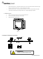
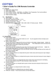
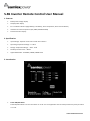
S-R6 Inverter Remote Control User Manual 1. Features • Battery bank voltage display • Output power display • Error condition indicator (High Battery, Low Battery, Over Temperature, Over Load conditions) • Indicator for status of operation (INV, GRID, POWER SAVING) • Failed connection display 2. Specification • Input Voltage : separate versions for 12 V & 24 V inverters • Operating Temperature Range : 0 – 40℃ • Storage Temperature Range : - 30℃ - 70℃ • Stand-By Current Draw : < 80mA • Applicable Models : SA-1000K / 2000K / 3000K Series 3. Introduction • Power ON/OFF Switch Power ON/OFF switch is to turn the inverter on or off. You are supposed to hear one beep sound every time you switch on or off. www.samlexamerica.com • Battery voltage indicator “BATTERY” This bar chart controls a light that will move up and down as the battery voltage changes. Ideally, the voltage should remain in the green area of the bar chart. If the voltage goes into the red area at the top and bottom of the graph, inverter may shut down. • Output power indicator “OUTPUT (%) POWER” The AC load watt chart indicates the power drawn from the inverter by the load. Ideally, the watt indicator should remain in the green & orange area of the bar chart. If the OUTPUT POWER indicator is up to the red area of the bar, the light will flash and the inverter will shut down for inverter safety. • Over voltage protection indicator “OVP” The over voltage protection indicator is to indicate that the inverter has shut down because its input voltage is above 12 / 24 VDC. • Under voltage protection indicator “UVP” The under voltage protection indicator is to indicate that the inverter has shut down because its input voltage is below 12 / 24 VDC. • Over temperature protection indicator “OTP” The over temperature protection indicator is to indicate that the inverter has shut down because of overheating. The over temp indicator will be OFF when the inverter cools down. • Overload protection indicator “OLP” The overload protection indicator is to indicate that the inverter has shut down because of short circuit or overload problems. • “INV” indicator The INV indicator is to indicate that the inverter is ready. • GRID indicator The GRID indicator is to indicate that the inverter is in Pass Through Mode & transferring Grid power to the load (Applicable to the versions with Transfer Relay). • PWR.SAV. Indicator Power saving functions are described below: LED Solid Flashing Off Meaning Ready Active Inactive Inverter Output ON OFF www.samlexamerica.com • Reverse Over-ride (ROF) and Ignition Lockout Functions The Recreation Vehicle Industries Association (RVIA) of America and some American states require that when a vehicle is in motion, the TV monitor should be switched off if it is in the view of the driver. Sometimes, the TV monitor is used in conjunction with a camera to enable the driver to view the area at the back of the vehicle when the vehicle is being reversed. The TV monitor should normally remain off (if it is in view of the driver) and should power on only when the gear is shifted to “reverse”. When the gear is shifted to “reverse”, a micro-switch in the reversing mechanism in the vehicle generates a “+” battery voltage signal that can be used to switch on the TV monitor. This is termed as “Reverse Over-ride Function (ROF)”. If the TV monitor is powered from the inverter, “ROF” function will enable to switch on the inverter when the vehicle is reversed and “+” battery voltage signal is fed to the Remote. Also, some low power circuits in a vehicle are energized when the ignition switch is turned to the “Accessory” position to provide “+” battery voltage power to low power devices like radio / CD player etc (the vehicle is not running in this position and hence, high power devices should not be powered as the starter battery will get drained and the vehicle may not start). When the ignition switch is turned to the “Accessory” position, a “+” battery voltage line is available for actuating the required devices. As the inverter is a high power consuming device, it should be switched off when the ignition switch is turned to the “Accessory” position. Hence, the “Ignition Lockout” function is utilized to switch off the inverter when “+” battery voltage signal is fed to the Remote on activation of the “Accessories” circuit In the back of the Remote Control, a ¼” male quick disconnect terminal is provided to switch on or switch off the inverter by feeding “+” battery voltage signal. A jumper is provided in the Remote Control (The jumper is accessible after opening the bottom cover of the remote control) to select either “ROF” function or “Ignition Lockout” function. The Remote Control comes preset in “ROF” position In the preset condition of “ROF”, when the “+” battery voltage signal from the reversing gear system is fed to the ¼” male disconnect terminal, the inverter is switched on. When “+” battery voltage signal is removed, the inverter is switched off. When the alternate “Ignition Lockout” function is selected (by changing the position of the internal jumper), the inverter shuts down when “+” battery voltage signal from the “Accessories” circuit is applied and switches on when the “+” battery voltage is removed. The wire used for feeding the “+” battery voltage signal to the ¼” connector for the ROF or Ignition Lockout functions should have a 0.5A fuse in series for protection. • Selecting ROF or Ignition Lockout Functions Jumper JP1 is placed inside the remote control and is used to select either Reverse Override Function or Ignition lockout Function (open the back cover for access to the jumper JP-1). JP1 jumper “Short” - Reverse Override Function* JP1 jumper “Open” – Ignition Lockout Function *Please note that the default mode is Short. • Connect the wire RJ-11 to the remote port in front of the panel. www.samlexamerica.com Ignition Lockout function – The ignition lockout function is to turn the Inverter OFF when the auxiliary input wiring is connected to the ACC, and “+” battery voltage signal is applied. Reverse Override Function – The Reverse Override Function is to turn the inverter ON when the auxiliary input wiring is connected to the reverse gear Shift, and “+” battery voltage signal is applied. • Installation Procedure 1. Refer to the drawing (see Figure 2) for hole and cutout dimensions. 2. Use the cable between S-R6 remote and the inverter. 3. Switch the inverter to REMO position. PHONE JACK JP 1 AUX Figure 2 4. Drawings of S-R6 Remote Control Cables CONDUCT OR I NS UL A T I ON J ACKET C A B L E S T R U C T U R E ( A- A) WARNING! DO NOT use standard telephone cable. www.samlexamerica.com