1
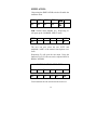
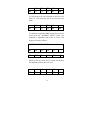
USER MANUAL
MULTI-PRO 2000
Electrical Safety Analyzer
&
Multi-Parameter Simulator
110 Toledo Street, Farmingdale, NY 11735
www.Netech.Org
Dear User,
We appreciate your purchase of Netech’s
Multi-Pro 2000, Electrical Safety Analyzer.
Properly used, the MULTI-PRO 2000
delivers more performance and accuracy
than any other Electrical Safety Analyzer in
its price range. This manual has been
designed as a tool to help you get the most
from your MULTI-PRO 2000. We suggest
that you carefully read this manual so that
you will be able to properly use and maintain
this product. We welcome any comments you
may have that could help us improve the
MULTI-PRO 2000 and this manual.
Netech is recognized as an innovator and
manufacturer of advanced affordable
instruments. When you buy our products we
guarantee absolute satisfaction.
Your
business is important to us and we are
dedicated to provide you with the best service
possible.
We are pleased you selected the MULTI-PRO
2000 to meet your needs. We hope you will
consider us again when you have a
requirement for accurate, reliable, versatile,
and yet affordable instruments.
Sincerely,
President
TABLE OF CONTENTS
GENERAL DESCRIPTION
Page
2
PREPARATION FOR USE
Page
3
CONTROL DESCRIPTION
Page
4
FRONT PANEL CONTROLS
Page
5
MODELS AND ACCESSORIES
Page
15
MAINTENANCE
Page
16
FUNCTIONAL DESCRIPTION
Page
17
SPECIFICATION
Page
18
WARRANTY
Page
23
GENERAL DESCRIPTION
The Multi-Pro 2000 is a compact, precision,
Electrical Safety Analyzer designed to be used for the
quick and easy measurement of Electrical Leakage
Current, and Power Cord Ground Resistance of any
electrically operated equipment. In addition to the
case leakage, leads leakage, isolation leakage and
power cord resistance measurement functions,
MultiPro incorporates a 12 lead EKG and
performance waveform including sine, square,
triangle, and pulse.
There are two leakage current modes. The first mode
measures leakage current from equipment chassis to
ground (case leakage). The second measures leakage
current between EKG leads and ground or to the LL
lead. In both modes the leakage current may be
measured under normal polarity reverse polarity and
open neutral. EKG lead isolation testing is performed
by applying isolated AC voltage to leads and by
measuring the leakage current from the leads to
ground or to the LL lead.
The power cord resistance is measured using a Kelvin
cable and an internal current source.
2
PREPARATION FOR USE
The Multi-Pro 2000 is shipped with a power cord and
Kelvin Cable. First, connect the Multi-Pro 2000 to an
AC outlet (110 or 220 Volt depending on the model
purchased).
Next, connect the Kelvin cable to the connector on
the rear panel of the MultiPro 2000.
Turn on the power via the main power switch on the
right side of the MultiPro. “NETECH” and the
software revision will be displayed. The display will
then display “MAIN MENU, Int, Ext, Cfg. (Int:Internal measurement, Ext:- External Measurement
Option, Cfg:- Configuration Option.
INT
F1
MAIN MENU
EXT CFG
F2
F3
From the tactile keypad select the function desired.
“Case Leakage, Lead Leakage, Simulator, Resistance
Measurement or F1 for Internal Measurement”
(Internal Measurement allows the user to accurately
measure line voltage and line polarity)
See section for control operation / description.
3
CONTROL DESCRIPTION
DISPLAY:
The Multi-Pro 2000 incorporates a vacuum florescent
display. The display ensures high readability even
under the lowest ambient light conditions.
KEYPAD:
The keypad utilizes soft touch tactile keypads,
Providing a fluid resistant barrier to the internal
circuitry.
POWER SWITCH:
The power switch located on the right hand side of
the Multi-Pro is a rugged 20 Amp switch. This switch
turns the power on/off to the Multi-Pro and the test
outlet.
TEST OUTLET:
The test receptacle used in the Multi-Pro is rated for
20 Amp. It will accept all standard line cords as well
as horizontally oriented neutral prongs on 20 Amp
line cords. Power to the test receptacle defaults to the
off mode. Manual selection of normal or reverse
polarity must be selected to energize the test
receptacle.
4
FRONT PANEL CONTROLS
There are 16 tactile switches on the front panel that
control all internal functions and measurement
parameters. An audio tone is heard as confirmation
that a key command was received by the
microprocessor.
OUTLET POWER:
Three switches control the AC power supplied to the
test receptacle. “Normal Polarity, Off, and Reverse
Polarity”. Depressing the “Normal Polarity” switch
will energize the test receptacle with normal polarity
AC power. Depressing the “Reverse Polarity” switch
will energize the test receptacle and reverse the
polarity. Depressing the “Off” (“Off Outlet”) switch
will remove power from the test receptacle.
INTERNAL MEASUREMENT:
As previously indicated, as part of the selftest/default setup, the display will read “Int – Select
Function”. The Int command (Internal Measurement)
is located above the F1 key. Depressing the F1 key at
this time will display the “Internal Measurement”
menu. Three options will be displayed. VOL (F1) for
line voltage measurement, CUR (F2) for optional
function and POL (F3) for line polarity
5
determination. Depressing F1 at this time will display
the line voltage in “Volts AC”. There is a 3 second
delay to allow for sampling time. Depressing F2 will
give you optional function. Depressing F3 will
activate the polarity determination circuit. At this
time “Checking” will be displayed. The polarity will
then be displayed as “Normal Polarity” or “Reverse
Polarity”. Should “Error” be displayed, there may be
a problem with the outlet the Multi-Pro is attached to,
or the line cord for the Multi-Pro may be defective.
CASE LEAKAGE:
The switch labeled “Case Leakage”, enables the
chassis or case leakage measurement function of the
Multi-Pro. Electrical leakage current, measured in
micro amps, is measured from the device under test
chassis or case to earth ground through the line cord
of the device under test. The display will read “CASE
LEAKAGE Select Polarity”.
Using the outlet power polarity selection switches,
select the polarity condition required to measure.
Selecting Normal Polarity will enable the leakage
current measurement mode. Leakage current will be
displayed after 2 seconds. The value displayed will
read “X .XX Micro Amp”, “NoP” and “Normal
Polarity” will also be displayed to indicate the
reading displayed is for the normal polarity
condition.
6
Depressing the Reverse Polarity switch also enables
the leakage current measurement mode. However,
“RvP” and “Reverse Polarity” will be displayed on
the display.
Open neutral tests can be performed by depressing
the F6 switch after the polarity is selected. The autorange feature of the MultiPro will select the
appropriate range automatically. For reading in
excess of 100 microamps, the decimal point will not
be displayed. The user can switch between Reverse
and Forward Polarity at any time to verify readings
or, to determine if any service action performed on
the device under test affects the readings.
CASE LEAKAGE: Using External Leads
Select case leakage. Attach the external lead (red) to
the input jack of the Multipro. Connect the other end
of the lead to the case of the unit under test. Case
leakage measurements can be made for various line
conditions, power on, off, normal or reverse polarity,
closed or open ground, Closed or open neutral.
Following the initial “OPEN GROUND” leakage
measurement:(App. 20 seconds) measurement mode
is switched to “CLOSED GROUND” leakage. In this
mode , external leakage on closed ground systems
can be measured using the external lead. (Red INPUT
jack on the ECG output panel)
LEADS LEAKAGE:
7
Depressing the Leads Leakage switch will display the
Leads Leakage menu.
LEADS
LEAKAGE
GND
LLR ISO
F1
F2
F3
F4
F5
F6
The following options are available: GND (F1), LLR
(F2), ISO (F3) . Depressing F1 (GND) enables the
“LEADS TO GND LEAKAGE” menu.
LEADS TO GND LEAKAGE
ALL
RL
RA
LA
LL
V1-6
F1
F2
F3
F4
F5
F6
Using the function keys (F1 – F6) select the desired
lead for the Lead Leakage mode of the Multi-Pro.
F1 will measure “ALL” leads to ground and will
display the reading as “X .XX Micro Amp” as with
Case Leakage “NoP” will also be displayed when
normal polarity lead leakage is selected. “RvP” will
be displayed if reverse polarity lead leakage is
selected. “Leads Leakage * ALL to GND *” will also
be displayed. Right Leg, RL(F2) Right Arm, RA (F3)
8
Left Arm, LA (F4) Left Leg, LL (F5) and Chest
Leads, V1 – 6 (F6) also read in the same way with
both forward and reverse polarity leakage readings to
ground indicated. With readings in excess of 100
microamps the decimal point will not be displayed.
There is a 2-second read time on all lead leakage
measurements.
From the main “LEADS LEAKAGE” menu
depressing F2 enables the “LEADS TO LL
LEAKAGE” menu.
LEADS TO LL LEAKAGE
ALL
RL
RA
LA
F1
F2
F3
F4
V1-6
F5
F6
This function measures all or selected leads to LL
(Left Leg).
Depressing F3(From main “LEADS LEAKAGE”
menu) activates the Isolation Leakage test. The line
voltage is applied to all leads while lead leakage is
measured. The leakage is displayed as ” X
XX Micro Amp” and is displayed within 2-seconds.
This test verifies that the isolation system on the
device under test is operating properly.
PATIENT SAFETY PRECAUTION:
9
SINCE
THE
TEST
METHOD
INJECTS
POTENTIALLY HAZARDOUS CURRENT LEVELS
INTO THE ELECTROCARDIOGRAPH AND THE
RELATED POWER SYSTEM , DO NOT CONDUCT
TESTS IN AN OCCUPIED PATIENT LOCATION OR
WHILE THE PATIENT IS CONNECTED TO A
RELATED POWER SYSTEM BRANCH CIRCUIT.
CAUTION:
THE EKG ISOLATION VOLTAGE IS 120 VAC AND
ALTHOUGH IT IS CURRENT LIMITED TO 1 mA, IT
IS POTENTIALLY LETHAL.
POWER CORD GROUND
RESISTANCE
To measure line cord ground resistance for the
device under test, depress the switch labeled
“RESISTANCE Measurement”. The display will read
“POWER CORD RESISTANCE/Connect Kelvin
Cable”. Once Kelvin cable is attached to a suitable
ground on the device under test, press the “READ”
switch on the front panel the unit will determine the
resistance in 3 seconds. Ground
resistance will be displayed in whole numbers “XX
mOhms/Cord Resistance”. An open ground condition
will result in the “Check Ground!!!” error message.
10
Unit Under Test
UUT
POWER CORD
KELVIN
CABLE
Resistance Measurement
NOTE:
Power is removed from the test outlet during
this test. This is done to prevent any damage to
the MultiPro or device under test in the event of
a ground fault or faulty wiring of the device
under test.
11
SIMULATOR:
Depressing the SIMULATOR switch will enable the
simulator menu.
NSR
SIN
SQR
TRI
PLS
F1
F2
F3
F4
F5
NSR: Normal Sinus Rhythm (F1), Depressing F1
will open up the “NORMAL SINUS” menu
RTE
F1
AMP
F6
The user can now select the rate “RTE” and
amplitude “AMP” of the normal sinus rhythm wave
form.
Depressing F1 will open the rate menu. Using the
function keys F1-F6 the rate can be adjusted from 30
BPM to 300 BPM.
NORMAL SINUS XXX BPM
30
60
70
80
90
>
F1
F2
F3
F4
F5
F6
F6 will advance the rate selection to the next level.
12
<
F1
100
F2
120
F3
150
F4
180
F5
>
F6
F6 will advance the rate selection to the next level
again. F1 will return the user to the previous rate
menu.
<
F1
210
F2
240
F3
270
F4
300
F5
F6
To enable the amplitude (AMP) menu, depress the F6
switch from the “NORMAL SINUS” menu. The
amplitude is adjustable from 0.1mv to 4.5mv. The
display will read as follows:
NORMAL SINUS X.XXmV
0.1
0.2
0.3
0.4
0.5
F1
F2
F3
F4
F5
F6
Similar to the rate menu, the F6 switch will advance
the amplitude menu to the next level.
<
F1
1mV
F2
1.5
F3
2mV
F4
13
2.5
F5
>
F6
F6 will advance the amplitude selection to the next
level again. F1 will return the user to the previous
amplitude menu.
<
F1
3mV
F2
3.5
F3
4mV
F4
4.5
F5
Sine, Square, Triangle, and Pulse function waveforms
all operate in a fashion identical to the normal sinus
rate and amplitude however, there are 29 possible
rate selections for each function waveform ranging
from .1 HZ to 100 HZ. The amplitude range is from
0.1mv to 4.5 mv in increments matching the normal
sinus rhythm menu.
Escape (ESC):
This switch when depressed will return the user to the
main Power up menu at any time.
MENU:
This switch when depressed will return you to the
menu last selected.
POWER CORD RECEPTACLE:
The power cord plugs into this receptacle. Plug the
power cord to AC supply to 110 VAC rated for 20
Amps. Remove the power cord when storing the unit
in the supplied carrying case.
14
FUSE:
Two separate fuses are provided.
Outlet - 20 A Max
Device - .25 A
Kelvin Cable:
The Kelvin cable is a two-conductor cable used to
measure the ground wire resistance of the line cord
for the device under test. This system ensures an
accurate measurement due to the nulling effect on the
test cable length.
STANDARD MODELS
Part No.
Description
Model
550-110
550-200
110V / 60HZ
220V/ 50 Hz
MULTI-PRO 2000
MULTI-PRO 2000
ACCESSORIES
551
552
553
553
1000
Soft Carrying Case
AC Power Cord 15 Amp
AC Power Cord 20A
Test Lead (Kelvin Cabe)
EKG snap stud to banana plug
15
Netech manufactures a wide variety of Biomedical
test equipment including; Patient Simulators,
Pacemaker
analyzer,
Defibrillator
analyzer,
Pressure/vacuum meters, SpO2 analyzers, Infusion
device analyzers etc.
Please call 1-800-547-6557 for a catalog or visit
our main Website www.Netech.Org
For the latest Safety analyzers visit
www.Electricalsafetyanlyzer.com
MAINTENANCE:
The MULTI-PRO 2000 requires only minimum
maintenance. In order to ensure the accuracy, it is
recommended that the unit be checked periodically.
Re-calibration is required on an annual basis. Field
calibration is not recommended. Netech factory
personnel should perform re-calibration. Netech
recalibration charges are very low compared to the
industry standard.
Clean the keypad with liquid eyeglass cleaner. Do
not use abrasives, solvents, or ammonia. Use light
pressure to prevent window from being pressed out
of position.
16
FUNCTIONAL DESCRIPTION
AAMI Load:
A simulated patient load is recommended by the
Association for the Advancement of Medical
Instrumentation & Safe current limit standard
(ANSI/AAMI ESI-1993). The AAMI standard test
load provides a constant 1uA/mV output independent
of frequency. The current to be measure is routed
directly to the AAMI load, which is then connected
to the input Amplifier.
RMS Converter and Amplifier:
The programmable amplifier amplifies the input
signal. The RMS converter generates a DC voltage
equal to the RMS value at its input. The Amplifier
then sets the gain for the measurements. When
leakage current measurement is selected by the front
panel switch, the AAMI LOAD is connected in front
of the INPUT AMPLIFIER, and the voltage
developed across it from the leakage current is
measured.
Current Source and Amplifier:
Resistance is measured by connecting the current
source to the resistance under measurement and
measuring the voltage with the input amplifier.
17
SPECIFICATIONS
CASE LEAKAGE:
Current Range:
0 - 20.0, 20.00 – 200.0, 200.0 - 2000 Micro-amps.
The Multi-Pro 2000 automatically selects the correct
range based on the initial measurement.
Accuracy:
Electrical Measurement
Current:
+/- 1% of full scale DC to 1 kHz
+/- 2.0% of full scale 1 kHz to 100
kHz
+/- 4% of full scale 100 kHz to 1
MHz
Resistance:
Voltage:
+/- 2% of range.
+/- 5% of range.
All Current measurements are made through a
standard AAMI Load. The meter readings correspond
to the RMS value of the current measured. All
components of the AAMI load are 1% tolerance.
POWER CORD RESISTANCE:
Resistance measurement ranges are 0 - 20.00 , 20.00 200.0, 200.0 – 2000.0 mOhms. The Multi-Pro 2000
automatically selects the correct range based on the
initial measurement. Values are obtained using the
supplied Kelvin cable. Accuracy is at +/- 2%.
18
LEAD LEAKAGE:
Current Range:
0 - 20.00, 20.00 - 200.0, 200.0 – 2000 Micro-amps.
The MultiPro 2000 automatically selects the correct
range based on the initial measurement.
Accuracy: +/- 1% of full scale DC to 1 kHz,
+/- 2.5% of full scale 1 kHz to 100 kHz,
+/- 5% of full scale 100 kHz to 1 MHz,
Isolation Test:
120 Volts AC applied to the leads through a 120K
ohm current limiting resistor. Current is limited to
1mA.
SIMULATOR:
Normal Sinus Rhythm, Full 12 lead configuration
Amplitude selections from 0.1 to 4.5 mV in 13 step
increments. Frequency selections from 30 to 350
Beats per minute in 14 steps.
PERFORMANCE WAVEFORMS:
Amplitude selections from .1 to 4.5 mv in 13 step
increments. Frequency selections from .1 to 60 Hz.
19
TEST LEAD JACKS:
The Case Ground and Reference Ground are standard
banana jacks.
EKG JACKS:
10 separate Jacks are provided for connecting the
EKG leads for simulation and leakage measurement.
POWER REQUIREMENTS:
110 VAC (220 VAC Optional) 50-60Hz, 20 Amps
maximum rated for the test outlet and 0.1 Amps rated
for the unit.
PHYSICAL DIMENSIONS:
Size: 10.25” X 6.25” X 2.5”
Weight: 4 lbs.
AMBIENT TEMPERATURE:
Operating range:
59-95 Degrees F (15-35°C)
Storage Temperature: 32-122 Degrees F (0-50°C)
20
INSTRUCTION FOR PRODUCT RETURN
Damaged in Transit:
All shipments are carefully examined by NETECH
and carefully packaged for shipment. They are
insured in the customer’s name with the carrier. On
receipt, if the shipping container appears to have been
damaged during shipment, the instrument should be
thoroughly inspected. The delivering carrier’s paper
should be signed noting the apparent damage. If the
instrument is damaged beyond use, a new order
should be placed with NETECH while awaiting
reimbursement from the carrier for the damage
instruments.
Malfunction:
Please follow these steps for repair or re-calibration
of your NETECH instrument:
1. Telephone NETECH 1-631-531-0100 for cost of
repair or Re-calibration, Repair Authorization
number (RA) and shipping instruction.
2. Obtain a purchase order number from your
purchasing department showing instruments
model number and cost of repair and/or recalibration.
21
3. Securely package your instruments in a strong
box surrounded by at least two inches of suitable
shock absorbing material. Include the purchase
order, or reference your purchase order on your
packing slip.
4. Mark the outside of the shipping box with the
supplied RMA number.
5. Forward the instrument prepared to Netech
NETECH CORP
110 Toledo Street
Farmingdale, NY 11735
ATTN: SERVICE DEPT.
Proud to be of your service since 1987
22
Operating Instructions
for
Multipro 2000 Storage and Printing
The Multipro 2000 is capable of printing test measurement results directly
to an optional printer or PC display, and of storing test measurement results for
later printing or display.
When measurements are made, the Multipro 2000 automatically stores
them in its main memory. This main memory is volatile memory and is cleared
whenever the Multipro 2000 is turned off. Test measurement results may be
saved in one of three non-volatile registers that will retain the results when the
Multipro 2000 is turned off. This stored data may be printed or displayed at a
later time.
RS 232 Setup:
Setting up the Hyper Terminal on your PC: (Windows XP)
1. Go to Startup – All Programs – Accessories – Communications –
HyperTerminal
2. When you click on Hyper Terminal a window will pop up and it will ask you
to configure a New Connection.
3. Select the first Icon and Enter the name as Multipro 2000 and hit ok
4. Another “Connect to” Window will pop up.
5. In that window select the port you want in the “connect using” tab. Select
COM1 generally. Hit ok
6. A new window named “ COM 1 Properties” will pop up. Specify the
following in it
• Bits per second: 9600
• Data Bits: 8
• Parity: None
• Stop Bit = 1
• Flow Control: Hardware
And hit ok
7. Now follow the below mentioned procedure.
8. You can save the HyperTerminal connection for future use so you don’t
have to follow these steps again.
The MultiPro 2000 can be connected to a printer or a PC via the RS 232C
SERIAL PORT located on the side of the instrument.
A. Performing Tests and Printing Results:
1. Turn on the Multipro 2000 and perform the desired tests following the
instrument’s standard instructions.
2. When all desired tests have been performed, the measurement results
may be printed directly to an optional printer or displayed on a PC by
pressing the PRN ‘F5’ key.
MAIN
F1
F2
F3
MENU
F4
PRN
MEM
F5
F6
3. Results may be printed with or without a header.
4. To print the header, press the HEAD ‘F1’ key.
To Print Header
‘F1’ Key Pressed
PRINT
HEAD
F1
MENU
RESULT
F2
F3
F4
F5
F6
Header:
DEVICE INFORMATION
TYPE:
MODEL:
CONTROL #:
MANF:
SERIAL:
LOC:
PHYSICAL INSPECTION
5. To print the measurement results press the RESULT ‘F3’ key.
To Print Measurement Results
HEAD
F1
‘F3’ Key Pressed
RESULT
F2
F3
F4
Example of Measurement Results:
Case Leakage Normal Pol:
Case Leakage Reverse Pol:
Case Leakage Power Off:
Leads Leakage All to GND:
2498.8 Micro Amp
2498.8 Micro Amp
2498.8 Micro Amp
2498.8 Micro Amp
F5
F6
B. Storing Measurement Results:
Test results may be stored in three non-volatile memory registers for later
printing or display.
.
1. Press MEM ‘F6’ from the Main Menu of the Multipro 2000.
Memory Selected
F1
‘F6’ Key Pressed
F2
F3
F4
PRN
MEM
F5
F6
2. Press STO ‘F1’ key.
Store Selected
‘F1’ Key Pressed
MEMORY
STO
RCL
CLR
F1
F2
F3
MENU
F4
F5
F6
3. Select the desired register for storage by pressing the ‘F1’, the ‘F2’, or the
‘F3’ key. The display will then indicate that the data has been stored.
Results Stored in Register 2.
‘F2’ Key Pressed
STORE
TO:
1
2
3
F1
F2
F3
F4
F5
F6
C. Printing Stored Results:
Test measurements that have been stored in registers 1, 2, and 3 may be
printed or displayed later.
1. Press the MEM ‘F6’ key from the main menu.
Select Memory from Main Menu
‘F6’ Key Pressed
MEM
F1
F2
F3
F4
F5
F6
2. Press the RCL ‘F2’ key.
Select Recall
‘F2’ Key Pressed
STO
RCL
CLR
F1
F2
F3
F4
F5
F6
3. Press the 1 ‘F1’, 2 ‘F2’, or 3 ‘F3’ key to print the stored results.
Select Stored Memory to Print from register 1
1
2
3
F1
F2
F3
‘F1’ Key Pressed
F4
F5
F6
D. Clearing the Memory
The stored information may be cleared. All three registers will be cleared
simultaneously.
1. Press the MEM ‘F 3‘ key from the Main Menu.
2. Press the CLR ‘F’ key.
To Clear the Memory
CLR ‘F3’ Key Pressed
STO
RCL
CLR
F1
F2
F3
F4
F5
F6
3. The display will momentarily indicate MEMORY CLEARED.
Memory Cleared
MEMORY
CLEARED
F1
F2
MEMORY
MENU
F3
F4
F5
F6
WARRANTY
Netech warrants to the original purchaser that the MULTIPRO 2000, as purchased from a Netech distributor or dealer,
will conform to the written specification as of the date of its
manufacture, for a period of one year from the date of purchase.
Netech Offers an additional second year warranty if the unit is
send to Netech for annual recalibration. Netech warrants this
MULTI-PRO 2000 against faulty workmanship and defective
materials for a period of one year from the date of purchased. If
the MULTI-PRO 2000 fails to conform to these warranties,
Netech will repair or replaced the MULTI-PRO 2000 and/or it’s
components within a reasonable period of time in the MULTIPRO 2000 is returned to Netech’s facility at Farmingdale, NY,
USA within the warranty period as expressed above. These
warranties are made upon the expressed condition that:
1.
The purchaser promptly notifies Netech in writing of any
non-conformity with the above warranty including a
detailed explanation of the alleged deficiencies.
2. The MULTI-PRO 2000 is returned to Netech at the buyer’s
expenses only after obtaining the proper authorization from
Netech.
3. Netech will not be liable for any incidental or consequential
damages.
4. In the opinion of Netech upon inspection, the MULTI-PRO
2000 has not been misused, altered, or damaged due to the
abnormal handling and/or operation.
5. Repairs to the MULTI-PRO 2000 and/or its components
have not been made by anyone other than Netech or one of
its authorized repair agents.
6. The MULTI-PRO 2000 has not been modified, altered, or
changed in any manner by anyone other than Netech or one
of its authorized repair agents.
7. All shipping and handling charges will be billed to the
purchaser.
THIS WARRANTY EXCLUDES ALL OTHER WARRANTIES,
WHETHER EXPRESSED OR IMPLIED, ORAL OR WRITTEN,
INCLUDING WITHOUT LIMITATION WARRANTIES OF
MERCHANTABILITY AND / OR FITNESS FOR A
PARTICULAR PURPOSE.
/Multipro_manual_R06/07/07
23