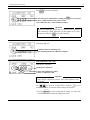
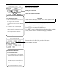
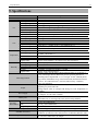
1
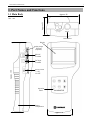
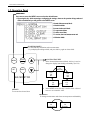
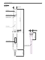
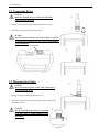
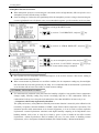
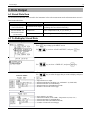
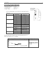
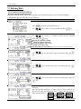
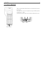
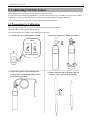
IAQ Monitor MODEL 2212 User’s Manual List of Components ■ Standard Item Model Qty. Features Main Body 2212-00 1 - Probe 2212-01 1 Carrying Case 2211-02 1 Probe Stand 2211-03 1 Used to hold and stabilize a probe Gas Calibration Cap 2211-04 1 Used for gas calibration Tube - 1 Used to connect the above gas calibration cap to a calibration gas cylinder Operation Manual - 1 - Manganese AA Batteries - 6 - Software CD-ROM 2212-41 1 Data Acquisition Software (for Windows) RS232C Cable 6000-02 1 Used to connect the instrument and PC CO, CO2, Temperature, Humidity Sensor ■ Options Item Model Features ZERO Gas 2211-05 Zero Point Calibration for CO and CO2 CO Span Gas 2211-06 CO Span Calibration (Approx. 35ppm) CO2 Span Gas 2211-07 CO2 Span Calibration (Approx. 1000ppm) Gas Valve 2211-08 Valve for the gas cylinders listed above Spare Probe 2212-01 Spare Probe Analog Output 2212-09 Analog Output Terminal AC Adapter 6113-02 Power Supply Printer (Recommended) DPU-S245 Printer Cable 6000-03 For printing out calculation results Printer cable for connecting the instrument with the printer. Table of Contents 1. Part Names and Functions ........................................................................ 1 1.1 Main Body............................................................................................................ 1 1.2 Operation Panel .................................................................................................... 2 1.3 Probe .................................................................................................................... 3 2. Getting Started ........................................................................................... 4 2.1 Installing Batteries ............................................................................................... 4 2.2 Connecting Probe ................................................................................................. 5 2.3 Disconnecting Probe ............................................................................................ 5 2.4 Turning ON/OFF the Power ................................................................................ 6 2.5 Precautions for Measurement............................................................................... 7 2.5.1 CO and CO2 Measurement Precautions ....................................................................... 7 2.5.2 Temperature Measurement Precautions ....................................................................... 8 2.5.3 Humidity Measurement Precautions ............................................................................ 8 3. Measurement (NORMAL MODE) .................................................................. 9 3.1 Changing the Measurement Mode ....................................................................... 9 3.2 Hold the Reading ............................................................................................... 10 4. Measuring MAX, AVG and MIN Value (CALUCULATION MODE) ........ 11 5. Measuring Percent Outdoor Air (%OA MODE) ....................................... 14 6. Data Output .............................................................................................. 18 6.1 Stored Data Item ................................................................................................ 18 6.2 To Redisplay Stored Data .................................................................................. 18 6.3 Printing out Measurement Data ......................................................................... 20 6.3.1 Preparation for Print Out ............................................................................................ 20 6.3.2 Printing from the NORMAL (Measurement) Mode .................................................. 20 6.3.3 Printing from CALCULATION mode ....................................................................... 21 6.3.4 Printing from %OA (Percent Outdoor Air) mode ...................................................... 21 6.3.5 Printing out Stored Data ............................................................................................. 22 6.4 Digital Output .................................................................................................... 24 6.4.1 Preparation for Digital Output ................................................................................... 24 6.5 Entering Commands from PC to Output Data ................................................... 25 6.5.1 Transmission of Raw Data (data measured every 1 sec)............................................ 25 6.5.2 Transmission of Stored Data (data stored in memory)............................................... 26 6.6 Analog Output (Optional) .................................................................................. 27 7. Other Settings ........................................................................................... 29 7.1 Changing Date and Time ................................................................................... 29 7.2 Changing Measurement Unit and Baud Rate ..................................................... 30 7.3 Deleting Data ..................................................................................................... 31 7.3.1 To Delete Certain Pages of Data ................................................................................ 31 7.3.2 To Delete All Data ..................................................................................................... 32 7.4 Contrast Adjustment .......................................................................................... 33 8. Calibrating CO/CO2 Sensor .................................................................... 34 8.1 Preparation for Calibration................................................................................. 34 8.2 Calibration Procedure – ZERO Calibration ....................................................... 35 8.3 Calibration Procedure – SPAN Calibration ....................................................... 38 9. Specifications ............................................................................................ 41 10. Calculation Result: DT, WB, AH and HR ........................................... 42 10.1 What is DT? ..................................................................................................... 42 10.2 What is WB? .................................................................................................... 42 10.3 What is AH? ..................................................................................................... 43 10.4 What is HR? ..................................................................................................... 43 11. Troubleshooting ...................................................................................... 44 11.1 Battery Check ................................................................................................... 44 11.2 Initial Operation Check .................................................................................... 44 11.3 Check While Measuring................................................................................... 44 11.4 Printer Check.................................................................................................... 44 11.5 Digital Output Check ....................................................................................... 45 11.6 Analog Output Check....................................................................................... 45 11.7 Calibration Check ............................................................................................ 45 12. Warranty and After-sales Service ........................................................ 46 13. Contact Information .............................................................................. 48 1. Part Names and Functions 1 1. Part Names and Functions 1.1 Main Body Approx. 88 Approx. 51 Unit: mm Probe Socket Display Analog output Terminal (Optional) RS232C Terminal Approx. 188 DC Input Terminal Power Switch I : ON O: OFF Operation Panel IAQ MONITOR Battery Compartment Approx. 66 1. Part Names and Functions 2 1.2 Operation Panel MENU KEY Press once to access the MENU screen to select the desired feature. * If pressing this key while measuring or configuring the settings, whatever the operation being conducted will be cancelled and you will go back to the MENU screen. …………………………Normal (Measurement) Mode ……………Calculation Mode …………………………………Percent Outdoor Air Mode ……………To output stored data ………………To delete stored data ………………………To set time, date and measurement unit ……………Calibration Mode START/HOLD KEY - To start and stop calculation and/or measurement. - To put displayed reading on hold, and press this key again to release hold. MENU SET START HOLD ▲,▼ NAVIGATION KEY 1. In the Normal (Measurement) Mode, this key is used to change the display item relating to humidity. (See P.9) CO2 CO Humidity MODE IAQ MONITOR CO2 CO DT CO2 CO WB SET KEY To execute the selected item. CO2 CO HR CO2 CO AH 2. In the MENU screen, this key is used to select a desired item or to set a numeric value. MODE KEY To change measurement mode between temperature and humidity. CO2 CO Temperature CO2 CO Humidity 1. Part Names and Functions 3 1.3 Probe Unit: mm Approx.φ25 CO Sensor Temperature Sensor Approx. 169 Humidity Sensor CO2 sensor Approx. 43 Approx. 320 Approx.φ32 Approx.φ15 Probe Number Approx. 53 L=Approx.2000 2. Getting Started 4 2. Getting Started 2.1 Installing Batteries Backside of the instrument 1. Press down the battery cover with your finger as shown left. 2. Slide the cover toward the bottom of the instrument. 3. Lift the cover away from the instrument. Types of batteries that can be used - Manganese (R6), AA batteries - Alkaline (LR6), AA batteries - Ni-Cd, AA batteries 4. Insert batteries ensuring the battery polarity is correct. This instrument requires six (6) AA size batteries. Types of batteries that can be used are: Manganese (R6), Alkaline (LR6) or Ni-Cd batteries. The six (6) batteries must be of the same type. Do NOT mix different types of batteries. Mixing different types of batteries or incorrect battery polarity may cause battery leakage or damage to the instrument. * Batteries CANNOT be recharged by the (optional) AC adapter. 5. Put the cover back on by reversing the above procedure. 2. Getting Started 5 2.2 Connecting Probe CAUTION * Make sure that the power is OFF when connecting or disconnecting the probe. 1. 1. Put the probe’s connector on the main body’s probe socket. 2. Push the connector in until you hear a click. CAUTION * DO NOT squeeze the probe into the main body or twist the probe when it is attached, as it may cause a serious damage to the instrument. Probe Socket 2. 2.3 Disconnecting Probe CAUTION * Make sure that the power is OFF when connecting or disconnecting the probe. A 1. Pull up the probe’s connector (See chart 1-A). 2. Pull out the connector from the main body with the connector up (See below chart 2). CAUTION * DO NOT twist the probe when it is connected, as it may cause a serious damage to the instrument. 1. 2 2. Getting Started 6 2.4 Turning ON/OFF the Power The power switch for turning ON/OFF the instrument is located at the side of the instrument. When powered up after a probe is connected, the KANOMAX logo, its model name and software version will be displayed for a few seconds before the measurement mode screen shows up. I: Power Switch Power ON Connect a probe to an instrument. O: Power OFF Power ON. The above warning will be displayed when a probe is not properly connected or not connected at all. If this warning shows up, turn off the instrument and check if a probe is connected properly. User Calibration Date Display Icons: (NORMAL Mode: For more details, see P.9) 1. Date and Time 4. Temperature (Humidity) 5. Battery Level Indicator 2. CO2 Concentration 3. CO Concentration 5. 1. 2. 3. 4. Measurement Screen (NORMAL Mode) Battery Level Indicator Check the “Battery Level Indicator” in the upper right corner to confirm the remaining battery level. When the battery level drops to a level requiring replacement, the indicator starts blinking. Since each battery has different battery life, it is recommended to replace them ahead. The below shows how the indicator changes as the batteries are running low: (blinking) --LOCK -When is displayed, the instrument will become inoperable even in the middle of measurement. Also please note that the measurement data will NOT be saved in this situation. Time to replace batteries 2. Getting Started 7 2.5 Precautions for Measurement 2.5.1 CO and CO2 Measurement Precautions Air diffusion condition (flow condition) affects the response time of CO and CO2 sensor. In order to obtain an accurate measurement result, perform a measurement in the place which has the flow of air as much as possible. Mechanism of CO and CO2 sensor has a limitation in accuracy when a measurement takes place under drastic thermal change. When the sensor and the measuring object have apparent thermal discrepancy, leave the probe in open air for at least 20 minutes before starting a measurement. After turning the power ON, sensor circuit requires some time to stabilize a detecting circuit. For an accurate measurement result, leave the instrument for about 5 minutes after turning the power ON. Keep this sensor away from expiratory air; exhaled air contains more than 10,000ppm of CO2 and exhaled air of smokers contains several ppm of CO. In order to perform an accurate measurement it is recommended to use the provided prove stand and to place the probe away from you while measuring. <How to use the Probe Stand> Lightly push the grip part of the probe into the probe stand’s holder as shown in the below figure 1. * Make sure to place the probe stand on a stable flat surface. Placing the probe on an unstable surface may cause the probe stand to fall and damage the probe. 2. 1. Holder Probe Stand <Precaution for Storing the Main Unit and Probe> * Our CO detection sensor inside the probe uses an electrochemical sensor. As this sensor uses electrochemical reaction, it reacts to not only CO but also the similar types of gas. If the sensor is used or stored in an environment containing organic solvents, paint, medical agents, oil or corrosive gas, the CO sensor will show an abnormal reaction causing zero-point drift, sensitivity variations or damage to the sensor. ◆ Typical Reactive Gas Hydrogen Sulfide, Sulphur Dioxide, Nitric Oxide, Nitrogen Dioxide, Chlorine, Hydrogen and Ethanol CAUTION * DO NOT use or store the instrument in the environment containing organic solvents, paint, medical agents, oil or corrosive gas. 2. Getting Started 8 <Atmospheric Pressure Correction> When atmospheric pressure at a measuring site is abnormal (such as at high altitude), follow steps below to set atmospheric pressure (default setting: 1013hPa). Since the change of weather does not significantly affect the atmospheric pressure as long as the measuring site is same (excluding the case of typhoon), once you set atmospheric pressure, you do not need to set it every time. Display Procedure Press key to bring up the MENU screen. Use key to select “7.CALIBRATION”, and press key. Use key to select “4. ATMOS. PRESS SET”, and press key. Use key to set atmospheric pressure value, and press key. Use key to select “5. SAVE INFO”, and press key to go back to the MENU screen and the setting is completed. 2.5.2 Temperature Measurement Precautions The response time for temperature measurement improves as the air flow increases. Wait for the reading to become stable before taking the data. When a measurement is performed in a no-airflow condition, the air temperature reading may become higher than the actual due to the heat generated by the lamp. It is recommended that the measurement is performed in an environment with at least 0.1m/s airflow to obtain accurate readings. 2.5.3 Humidity Measurement Precautions If a measurement is performed in the place where the humidity is high for a long period of time or temperature changes rapidly, humidity reading may become exceedingly high due to dew condensation. When dew condensation is built up, leave the probe in the atmosphere of less than 40%RH for 24 hours to dry it out. -- Comparison with Assman Aspiration Psychrometer -The quality and accuracy of IAQ Monitor’s humidity measurement function is ensured by strict calibration with traceability in Japanese National Standards of JEMIC (Japan Electric Meters Inspection Corporation). This instrument provides stable measurement as an electronic hygrometer, so it can be used as Assman Aspiration Psychrometer. Assman Psychrometer sometimes reads higher humidity comparing to the IAQ Monitor since handling methods such as how to wrap the wet bulb by gauze or how to handle the dirt affect Assman Psychrometer. Assman Psychrometer shall be handled with care. For more details on handling Assman Psychrometer, refer to the Japanese Industrial Standard (JIS) Z 8806 Humidity - Measurement Method. 3. Measurement 9 3. Measurement (NORMAL MODE) This is the mode that you will see when you turn on the instrument. In this mode you cannot store any data. Any displayed readings are updated every 1 second. To move to NORMAL Mode from other measurement mode, press key to bring up the MENU screen, select “1. NORMAL” and press key. 3.1 Changing the Measurement Mode Display 1. Procedure Press key when the NORMAL (Measurement) mode screen shown in the left is displayed. As key is pressed, the measurement mode will be switched between 2. (CO2, CO, Temperature) → 1. (CO2, CO, Humidity). 2. <CO2, CO and Humidity Measurement Screen> Press key when the screen in the left is displayed to change the humidity related display mode in the sequence of Humidity, 3.Dew-point Temperature [DT], 4.Wet-bulb Temperature [WB], 5.Absolute Humidity [AH] and 6.Humidity Ratio [HR]. See P.42 for detailed information on each item. 3. <Due-point Temperature Measurement Screen> 4. <Wet-bulb Temperature Measurement Screen> 5. <Absolute Humidity Measurement Screen> 6. <Humidity Ratio Measurement Screen> 3. Measurement 10 3.2 Hold the Reading Display Procedure When the NORMAL (Measurement) mode screen is displayed, press key (also available on Humidity measurement mode). “HOLD” indicator appears on the left side of the display to indicate that the reading shown is kept on hold on the display. Press key again to recover from the HOLD mode. Maximum Value Hold ····· How to Hold the Maximum Value Display Procedure When the NORMAL (Measurement) mode screen is displayed, keep pressing While key. is being pressed, “HOLD” indicator keeps appearing on the left side of the display and the maximum values of each parameter (CO, CO2, Humidity or Temperature) are shown on the screen. Release Press key to keep the maximum value on hold on the display. again to recover from the HOLD mode. 4. Measuring MAX, AVG and MIN Value 11 4. Measuring MAX, AVG and MIN Value (CALUCULATION MODE) In Calculation Mode measurement data is stored and maximum, mean and minimum values will be calculated. TRIAL(1) TRIAL(2) ………………… TRIAL(N) ● Average (AVG) AVG=ΣTRIAL(N)/N ● Maximum (MAX) MAX=TRIAL(i) Sampling Time Measurement Time ····· Sampling Time × N (Number of Trial) Display ● Minimum (MIN) MIN=TRIAL(j) Procedure Press Use key to bring up the MENU screen. key to select “2. CALCULATION” and press key. CALCULATION MODE SETTING SCREEN Total Memory Remaining Memory 1. CALCULATION MODE AVERAGE: Average every second’s data during sampling time, and make it as one measurement data. INSTANT: Make an instantaneous value per each sampling time as one measurement data. 2. SAMPLING TIME (1 ~ 999 sec.) Set the length of sampling time. 3. No. TRIAL (1 ~ 999) Set how many data to read every sampling time that has been set. 4. DATA STRORAGE (YES or NO) 5. SET TO START Save the setting and return to the standby screen. 4. Measuring MAX, AVG and MIN Value Display 12 Procedure <To set CALCULATION MODE> Use key to select “1. MODE”, and press Use key to select either “AVERAGE” or “INSTANT” and key. key. press <To set SAMPLING TIME> key to select “2. SAMPLING TIME”, and press Use key. key to set SAMPLING TIME (1-999sec) and press Use key. <To set the number of measurement data> Use key to select “3. No. TRIAL (N)”, and press Use key to set the number of TRIALs (1-999 times) and press key. key. Data for the number of TRIALs set here will be saved as raw data. <DATA STORAGE YES/NO> Use key to select “4. DATA STORAGE ?”, and press key. Use key to select YES or NO and press key. * You CANNOT store more than what is left in the memory. If you set the number more than the number of remaining data locations, it automatically adjusts to the amount of remaining memory. (For example, if the remaining memory is R0020/1500, you can only measure 20 times at the most.) <To save the settings> Use key to select “5. SET TO START”, and press key. (The display shown in the left indicates that it takes 50 measurements every 1 second (50 seconds in total).) <Standby Screen> This is a standby screen before measurement starts. Press key to start measuring. 4. Measuring MAX, AVG and MIN Value Display 13 <While Measuring> Procedure Press key to stop measuring. (If “YES” is selected for “4. DATA STORAGE ?”, the measured data will be stored.) You can also stop measuring by pressing key. However, any measured data will not be stored. <Calculation Result Display> After all the measurements are finished, the calculation result will be displayed. Use key to check each parameter in the sequence of CO2 -> CO -> Temperature -> Humidity -> Dew-point Temperature (DT) -> Wet-bulb Temperature (WB) -> Absolute Humidity (AH) -> Humidity Ratio (HR). As for Dew-point Temperature, Wet-bulb Temperature, Absolute Humidity, and Humidity Ratio, only average values will be displayed. Press key to return to the MENU screen. Calculation data will be stored when “4.DATA STORAGE” is set to “YES”. Related Functions: ■ If a printer is connected: press ■ To redisplay stored data -- P.18 ■ To print out measured data -- P.20 ■ What is DT, WB, AH, HR? -- P42 key to print out calculation result. 5. Measuring Percent Outdoor Air 14 5. Measuring Percent Outdoor Air (%OA MODE) %OA MODE is a measurement mode to calculate Percent Outdoor Air either with temperature or CO2. The calculation is based on below formula: Outdoor Air (O_A) %OA=(R_A – S_A) / (R_A – O_A) × 100 * %OA: Percent Outdoor Air R_A: Temperature or CO2 concentration of Return Air Return Air (R_A) S_A: Temperature or CO2 concentration of Supply Air O_A: Temperature or CO2 concentration of Outdoor Air A measurement takes place in the following sequence; Return Air -> Supply Air -> Outdoor Air Return Air (R_A) TRIAL (1) (2) (3)……(N) Supply Air (S_A) Supply Air (S_A) TRIAL (1) (2) (3) ……(N) Outdoor Air (O_A) TRIAL (1) (2) (3) …… (N) Time required to measure at each point --- Sampling Time × N (Number of Trial) Return Air Supply Air Outdoor Air : R_A=ΣTRIAL(N)/N : S_A=ΣTRIAL(N)/N : O_A=ΣTRIAL(N)/N <Calculation Result> * Percent Outdoor Air (%OA) %OA = (R_A - S_A) / (R_A - O_A) x 100 Average value in each point is used to calculate percent outdoor air. Temperature or CO2 concentration data at each point (TRIAL(1) ~ TRIAL(N)) will be also stored in the memory. 5. Measuring Percent Outdoor Air 15 Display Procedure Press key to bring up the MENU screen. Use key to select “3. %OA”, and press key. <To set SAMPLING TIME > Use key to select “1.MODE”, and press Use key to select “TMP.” or “CO2”, and press key. key. PERCENT OUTDOOR AIR (%OA) MEASUREMENT MODE SETTING SCREEN 1. CALCULATION MODE TMP.: To read temperature value and perform calculation. Total Memory CO2: To read CO2 concentration value and perform calculation. 2. SAMPLING TIME (1-999 sec.) Remaining Memory Set the length of sampling time/ (instantaneous value). 3. No. TRIAL(N) (1-999 times) Set how many data to read every sampling time that has been set. 4. DATA STORAGE (YES/NO) 5. SET TO START Save the setting and return to the standby screen. <To set SAMPLING TIME> Use key to select “2.SAMPLING TIME”, and press key. Use key to set sampling time (1-999sec), and press key. <To set Number of Trials> Use key to select “3.No.TRIAL”, and press Use key to select the number of trials (1-999 times), and press key. key. 5. Measuring Percent Outdoor Air Display 16 <DATA STORAGE> Use Procedure key to select “4.DATA STORAGE ?”, and press key. Use key to select “YES” or “NO” for data storage, and press key. <To save the settings> Use * If pressing key to select “5.SET TO START”, and press key. key before completing the settings, you will return to the MENU screen without that the changes are saved. 1. 2. 3. 4. 5. 1. 2. 3. 4. 5. 1. 2. 3. 4. 5. <Standby Screen> This is a standby screen before a measurement starts. Press key to start measuring. Display Icons: 1. RDY.: Current Status (READY/SAMPLE) 2. N 1: Current number of data measured 3. / 50: Total number of data to be measured according to the setting. 4. TMP.: Indicates that temperature value will be read to perform calculations. (When CO2 Mode is selected, “CO2” will be displayed.) 5. R_A: Displays what measuring point will be used. (R_A: Return Air, S_A: Supply Air, O_A: Outdoor Air.). <While Measuring> Press key to pause measuring, and press * You can stop measuring by pressing key again to resume. key. However, any measured data will not be saved. <Waiting for the next measurement point> After Return Air (R_A) measurement is completed, “NEXT” will show up at the top to indicate that it is waiting for the next Supply Air (S_A) measurement to be started. After that, Supply Air (S_A) measurement and Outdoor Air (O_A) measurement will be performed respectively. 5. Measuring Percent Outdoor Air 17 Display Procedure <Calculation Result> After all the measurements are finished, the calculation result will be displayed. Press key to display average values of Return Air (R_A), Supply Air (S_A), and Outdoor Air (O_A) at each point. Press key to return to the MENU screen. When “YES” is selected for “DATA STORAGE”, the calculation result will be stored. Related Functions: ■ When printer is connected, press ■ To redisplay stored data – P.18 ■ To print out measured data – P.20 key to print out the calculation result. 6. Data Output 18 6. Data Output 6.1 Stored Data Item The measurement data that can be stored in the instrument in the each measurement mode and measurement screen is listed in the table below. Measurement Mode Measurement Display CALCULATION Mode All measurement display (CALCULATION) Percent Outdoor Air Measurement Mode (%OA mode) Stored Parameters CO2, CO, Temperature, Humidity (including all items related to humidity) Temperature. %OA, Temperature of R_A, S_A, and O_A CO2 %OA, CO2 concentration of R_A, S_A, and O_A 6.2 To Redisplay Stored Data Display Procedure Press key to bring up the MENU screen. Use key to select “4.DATA OUTPUT”, and press Use key to select “1.DISPLAY”, and press key. key. <To set page> CALCULATION Use key to select the page that you want to display, and press key. ……………………………Page number to be output ………Measurement Mode (Calculation (A): AVERAGE / (I): INSTANT) ………………Measurement Date (Year/Month/Day) ………………Measurement Time (Hour/Minute/Second) ……………………………Number of Trial in the selected page %OA %OA ……………………………Page number to be output ……………Measurement Mode (%OA (TMP.): Temperature or (CO2): CO2 ) ………………Measurement Date (Year/Month/Day) ………………Measurement Time (Hour/Minute/Second) ……………………………Number of Trial in the selected page 6. Data Output 19 Display Procedure CALCULATION <Measurement data display screen> Measurement data of the specified page will be displayed. key to scroll the data. Use When a measurement is performed in the CALCULATION mode, press key to switch to display between Temperature and Humidity. Data No. CO2 CO Temp. %OA (Temperature) <To display calculation result> You can specify the data range for calculation. (When data range does not need to be changed, press key to display the calculation result of the data range shown.) Press Data No. Return Air Supply Air Temp. Temp. Outdoor Air Temp. %OA (CO2) Use key to show a cursor on “START” No. key to select data number where to start calculation (START), and press Use key to select data number where to end the calculation (END), and press Press key. The cursor will move to “END” No. key. key to display the calculation result of the data range selected. * You cannot select more than one range. Data No. Return Air CO2 Supply Air Outdoor Air CO2 CO2 CALCULATION TION <In CALCULATION mode > Press key to display calculation result in the sequence of CO2 -> CO -> Temperature -> Humidity -> DT, WB, AH -> HR. Only average value is displayed for DT, WB, AH, and HR. %OA < In %OA mode > Press key to display the average value of each point in the sequence of %OA -> R_A -> S_A -> O_A. Press key to return to the screen for data output page setting screen. Press key to return to the MENU screen. 6. Data Output 20 6.3 Printing out Measurement Data To print out stored measurement data, a printer cable must be connected to the RS232C terminal located at the side of the instrument. Note1:Although you can see both RS232c mark ( ) and USB mark ( near the terminal, only RS232c is available for this instrument. RS232C Terminal (Note 1) ) 6.3.1 Preparation for Print Out <Need to prepare> - Printer (optional)…recommended model: DPU-H245 (Seiko Instruments) - Printer Cable (optional) <Side of the Instrument> <Baud rate setting> The baud rate setting of the instrument and printer must be consistent. List of communication protocol for IAQ Monitor: Data Bit Length 8 bit Parity None Stop Bit 1 Delimiter CRLF Baud Rate Based on the set value* * As for setting BAUD RATE, refer to “7.2 Changing Measurement Unit and Baud Rate” (Page 30). * As for setting the printer, refer to the printer’s operation manual. <Connecting the instrument with a printer > 1. Connect a printer to the instrument by inserting a connecting cable into RS232 terminal located at the side of the instrument. 2. Turn ON the power of the instrument first, and then turn ON the printer. 3. Make sure that the instrument is in NORMAL Mode. 6.3.2 Printing from the NORMAL (Measurement) Mode Display Procedure When a NORMAL mode screen is displayed, press key to HOLD the readings that you want to print out. Press key to print out the display which is on hold at the time. If a printer is not connected properly, “PERR” will be displayed in lower left of the display. Examples of Data Printout <NORMAL Mode> 2004/05/12 15:40:45 CO2 523 PPM CO 1.7 PPM Temperature 24.4 ゚ C Humidity 52.7 %RH …………CO2 …………CO …………Temperature …………Humidity 6. Data Output 21 6.3.3 Printing from CALCULATION mode Display Procedure After the calculation measurement is completed and the calculation result is shown, press key to print out the measurement result. 6.3.4 Printing from %OA (Percent Outdoor Air) mode Display Procedure After %OA measurement is completed and the calculation result is shown, press key to print out the measurement result. Calculation Result Stored Page Measurement Mode Measurement Date Measurement Time Atmospheric Pressure Setting No. of Data Sampling Time Calculation Data Range CO2 Return Air CO Supply Air Temperature Outdoor Air % Outdoor Air Humidity Dew-point Temperature Wet-bulb Temperature Absolute Humidity Humidity Ratio PAGE SET PAGE :002 MODE :%OA(TMP.) DATE :2004/06/19 TIME :13:35:23 ATM. :1013hPa DATA :003 SAMPLING TIME:001 START:001 END:003 MAX 25.5 ゚ C AVG 25.4 ゚ C MIN 25.4 ゚ C MAX 24.3 ゚ C AVG 24.2 ゚ C MIN 24.1 ゚ C MAX 23.2 ゚ C AVG 23.0 ゚ C MIN 22.8 ゚ C %OA 85.4 %OA R_A R_A R_A S_A S_A S_A O_A O_A O_A Calculation Result PAGE SET PAGE :004 MODE :CALCULATION(I) DATE :2004/06/19 TIME :17:24:33 ATM. :1013hPa DATA :005 SAMPLING TIME:001 START:001 END:005 MAX 612 PPM CO2 AVG 598 PPM CO2 MIN 567 PPM CO2 MAX 1.2 PPM CO AVG 0.9 PPM CO MIN 0.7 PPM CO MAX 25.6 ゚ C AVG 25.6 ゚ C MIN 25.5 ゚ C MAX 64.6 %RH AVG 64.5 %RH MIN 64.4 %RH DT 15.4 ゚ C WB 18.1 ゚ C AH 7.5 g/m3 HR 6.4 g/kg <%OA mode> Measurement Condition Measurement Condition Examples of Printout <CALCULATION mode> 6. Data Output 22 6.3.5 Printing out Stored Data Display Procedure Press key to bring up the MENU screen. Use key to select “4.DATA OUTPUT”, and press Use key to select “2.PRINTER”, and press Use key to select the page that you want to display, and press key. key. key. Page No. to be output Measurement Mode (Calculation (A): AVERAGE / (I): INSTANT) Measurement Date (Year/Month/Day) Measurement Time (Hour/Minute/Second) The number of trials in the specified page number The data in the selected page will be displayed. Press down. key to scroll Data Range for calculation Data No. CO2 CO Temperature When a measurement was performed in CALCULATION mode, press key to switch to display between temperature and humidity. <To specify the data range for calculation> You can specify the data range for calculation. (When data range does not need to be changed, skip this step.) Press key to key to show a cursor at “START” No. Use select data number (START) where to start calculation, and press The cursor will move to “END” No. Use number (END) where to end the calculation, and press Press key. key to select data key. key to bring up the PRINT OUTPUT screen to select what to print out. Use key to select 1, 2 or 3, and press key to print out. 1. RESULT: Print out measurement condition and calculation result 2. DATA: Print out measurement condition and measurement data. 3. ALL: Print out measurement condition, calculation result and measurement data. 6. Data Output 23 Example of Printout <CALCULATION Mode> PAGE SET PAGE :011 MODE : CALCULATION(I) DATE :2004/06/21 TIME :16:23:08 ATM. :1013hPa DATA :005 SAMPLING TIME :001 START:001 END:005 MAX 612 PPM CO2 AVG 598 PPM CO2 MIN 567 PPM CO2 MAX 1.2 PPM CO AVG 0.9 PPM CO MIN 0.7 PPM CO MAX 25.6 ゚ C AVG 25.6 ゚ C MIN 25.5 ゚ C MAX 64.6 %RH AVG 64.5 %RH MIN 64.4 %RH DT 15.4 ゚ C WB 18.1 ゚ C AH 7.5 g/m3 HR 6.4 g/kg NUM. PPMCO2 PPMCO ゚ C 001 612 1.2 002 601 1.0 003 598 1.0 004 577 0.7 005 567 0.7 <%OA Mode> Measurement Condition (These items are printed out all the time.) Calculation Result (RESULT) 25.6 25.6 25.5 25.6 25.5 Measurement Data (DATA) PAGE SET PAGE :002 MODE :%OA(TMP.) DATE :2004/06/19 TIME :13:35:23 ATM. :1013hPa DATA :010 SAMPLING TIME:001 START:001 END:010 MAX 25.5 ゚ C R_A AVG 25.4 ゚ C R_A MIN 25.4 ゚ C R_A MAX 24.3 ゚ C S_A AVG 24.2 ゚ C S_A MIN 24.1 ゚ C S_A MAX 23.2 ゚ C O_A AVG 23.0 ゚ C O_A MIN 22.8 ゚ C O_A %OA 85.4 %OA NUM. ゚ CR_A ゚ CS_A ゚ CO_A 001 25.5 24.3 23.2 002 25.5 24.2 23.1 003 25.5 24.2 23.1 004 25.4 24.2 23.1 005 25.4 24.2 23.0 006 25.4 24.2 23.0 007 25.4 24.2 23.0 008 25.5 24.2 22.9 009 25.4 24.1 22.9 010 25.4 24.1 22.8 6. Data Output 24 RS232C Terminal (Note 1) 6.4 Digital Output 6.4.1 Preparation for Digital Output For digital-outputting stored measurement data, RS232C cable must be connected to the RS232C terminal located at the side of the instrument. Note1:Although you can see both RS232c mark ( ) and USB mark ( ) near the terminal, only RS232c is available for this instrument. <Need to prepare> - Computer - RS-232C cable (provided) - Communication Software (Measurement Software (CD-ROM) for Windows is provided) <Side of the Instrument> < Baud rate setting > The baud rate setting of the instrument and computer must be consistent. List of communication protocol for IAQ Monitor: Data Bit Length 8 bit Parity None Stop Bit 1 Delimiter CRLF Baud Rate Based on the set value* * As for setting BAUD RATE, refer to “7.2 Changing Measurement Unit and Baud Rate” (Page 30). * As for setting the computer, refer to the computer’s operation manual. <Connecting the instrument with a computer> 1. Connect a computer to the instrument with the RS232 cable. 2. Turn ON the power of the instrument. 3. Make sure that the instrument is in NORMAL Mode. RS232C Cable Wiring Diagram PC (D-Sub9 pin) Signal Pin No. NC RXD TXD NC GND NC RTS CTS NC 1 2 3 4 5 6 7 8 9 Connection IAQ Monitor (MODEL2212) Pin No. Signal Description of Signal Signal Direction 1 2 3 4 5 6 GND TXD RXD CTS RTS NC Signal Ground Transmit Data Receive Data Clear to Send Request to Send Output Input Input Output 6. Data Output 25 6.5 Entering Commands from PC to Output Data As for connecting your PC to the instrument, Command refer to “6.4.1 Preparation for Digital Output” (Page 24). D**** N S U -----Icon and its meaning----F : Space G : Line Break or to Press [Enter] key P *: To enter any number T**** M**** * Enter all commands in capitals. B Function To set how many data to read Receive Interrupt To output measurement condition To output measurement unit To set to output humidity related data To cancel outputting humidity related data To output stored number of the page To output stored data To output measurement condition To output measurement condition of all the pages 6.5.1 Transmission of Raw Data (data measured every 1 sec) Display Procedure Example: When entering “D0005 ” in Measurement <To set number of data to be read> Mode. Enter “D**** ”. (Enter the number of data to be read in 4 digit number.) After the command is received, “AD” will be returned. Then AD the raw data which is displayed on the instrument’s screen every one 0.9; 576; 23.4; 63.4 second will be output. The maximum number of data which can be set 0.8; 556; 23.4; 63.3 is 9999. When to read more than 9999 data, send another command. 0.8; 534; 23.5; 63.2 What will be output? 0.9; 540; 23.5; 63.2 CO; CO2; Temperature; Humidity 0.9; 561; 23.4; 63.3 AN Display AS CTH;00;00;1013 Display AU ppm;ppm;゚ C;%RH;゚ C;゚ C;g/m3;g/kg;% <Receive Interrupt> Enter “N ”. After the command is received, “AN” will be returned and the reception will be interrupted Procedure <To output measurement condition> Enter “S ”. After the command is received, “AS” will be returned. The display range of measurement items shown on the screen and configured atmospheric pressure will be output. What will be output? CTH: CO measurement range; temperature measurement range; configured atmosphere pressure CO measurement range: 00:0~50PPM / 01:0~500PPM Temperature measurement range: 00:0~60 oC / 01:-20~60 oC Procedure <To output measurement unit > Enter “U ”. After the command is received, “AU” will be returned. Configured measurement unit at the time will be output. What will be output? CO Unit; CO2 Unit; Temperature Unit; Humidity Unit; Dew-point Temperature Unit; Wet-bulb Temperature Unit; Absolute Humidity Unit; Humidity Ratio Unit; Percent Outdoor Air Unit 6. Data Output 26 6.5.2 Transmission of Stored Data (data stored in memory) Display AF Display AG Display AP P0011 Display AT 2004/05/19;13:32:26 0.9; 576; 001; 002; 0.8; 556; 003; 0.8; 534; 004; 0.9; 540; 005; 0.9; 561; 23.4; 23.4; 23.5; 23.5; 23.4; 63.4 63.3 63.2 63.2 63.3 Procedure <To set humidity related data output> Enter “F ”. After the command is received, “AF” will be returned and humidity related data such as DT, WB, AH, and HR will be added in the subsequent data output. Procedure <To release humidity related data output > Enter “G ”. After the command is received, “AG” will be returned and humidity related data such as DT, WB, AH and HR will not be added in the subsequent data output. Procedure <To output stored page number > Enter “P ”. After the command is received, “AP” will be returned and the stored page number will be output. Procedure <To output stored data > Enter “T**** ”. (Enter the page number of the stored data you want to output in 4 digit number.) After the command is received, “AT” will be returned. The raw data stored in the specified page will be output. *Any calculation data such as min, average and max value, will not be output. (As for %OA, only the average value in a page will be output. *The measurement unit in the output data depends on the current measurement unit setting. What will be output? - CALCULATION Mode (Before sending [F] command) * YY/MM/DD format is configured Data No.; CO; CO2; Temperature; Humidity as the date format in the output. - CALCULATION Mode (After sending [F] command) Therefore, the date setting on the Data No.; CO; CO2; Temperature; Humidity; DT; WB; AH; HR instrument will not be reflected in - Percent Outdoor Air (%OA) Mode the output. Data No.; %OA; R_A; S_A; O_A Display Procedure <To output measurement condition> AM Enter “M**** ”. (Enter the page number of the measurement condition CTH;000;001;003;AVG;1013 to be output in 4 digit number.) After the command is received, “AM” will be returned and the measurement condition of the specified page will be output. 1. 2. 3. 4. 5. What will be output? 1. Measurement Mode 000: CALCULATION Mode 001: %OA Mode 2. Sampling Time Display 3. Number of Data 4. Calculation Mode CALCULATION Mode-- AVG: average/ INS: Instant %OA Mode -- TMP: Temperature/ CO2: CO2 5. Configured Atmosphere Pressure Procedure AB CTH;000;001;003;AVG;1013 CTH;001;001;005;TMP;1013 <To output measurement condition of all pages> Enter “B ”. After the command is received, “AB” will be returned and the measurement condition of all pages will be output. (Output items are the same as when to output measurement condition.) Display ED Procedure <Error Message> If the page number is entered incorrectly, “ED” will be returned. 6. Data Output 27 6.6 Analog Output (Optional) 1. Data Update Interval …… 1 second 2. Load Impedance………… 5KΩ and above 3. Output Voltage……………DC 0-1V Analog Output Terminal As For the analog output, you can select one output range from the table below. Conversion Formula Output Range (Voltage: V) CO (C) 0 ~ 50 ppm C = 50 ×V ppm 0 ~ 100 ppm C = 100×V ppm 0 ~ 250 ppm C = 250×V ppm 0 ~ 500 ppm C = 500×V ppm CO2 (M) 0 ~ 500 ppm M = 500×V ppm 0 ~ 1000 ppm M = 1000×V ppm 0 ~ 2500 ppm M = 2500×V ppm 0 ~ 5000 ppm M = 5000×V ppm Temperature (T) 0 ~ 50 oC T = 50 ×V oC o 0 ~ 100 C T = 100×V oC o -20 ~ 30 C T = 50 ×V – 20 oC -20 ~ 80 oC T = 100×V – 20 oC o Temperature (F) 32 ~ 122 F F = 90 ×V + 32 oF 32 ~ 212 oF F = 180×V + 32 oF o -4 ~ 86 F F = 90 ×V – 4 oF o -4 ~ 176 F F = 180×V – 4 oF Humidity (H) 0 ~ 50 %RH H = 50 ×V %RH 0 ~ 100 %RH H = 100×V %RH It is linear output whose minimum value is 0V and maximum value is 1V. Output data is output every 1 sec constantly. How to Output Measurement Data (Analog Output) Explanation Voltage Take data every 1 second, and output the value every 1 second. 0 1 2 3 4sec. (Measurement Time) 6. Data Output 28 Display Procedure Press key to bring up the MENU screen. Use key to select “6.UTILITY”, and press Use key to select “3.ANALOG OUTPUT”, and press key. key. <To select measurement item to output > Use key to Select “1.OUTPUT SELECT”, and press Use key to switch in the sequence of “CO”, “CO2”, “TMP.” key. (Temperature) and “HUM.” (Humidity). Select the measurement item to output, and press key. <To set output range> Use key to select “2.”, and press Use key to select the output range, and press key. key. <To save the setting> Use key to select “3.SAVE INFO”, and press key to save the setting. * If pressing key before completing the setting, you will return to the MENU screen without that the changes are saved. 7. Other Settings 29 7. Other Settings 7.1 Changing Date and Time Display Procedure Press key to bring up the MENU screen. Use key to select “6. UTILITY”, and press Use key to select “1. TIME ADJUST”, and press Use key. key. key to select the item that you want to change (“1.STYLE”, “2.DATE” or “3.TIME”), and press key. 1.STYLE: Select from among JP, US and EU JP (Japanese) style YYYY/MM/DD US style MM/DD/YYYY EU style DD/MM/YYYY 2.DATE: Date 3.TIME: Hour/Minute/Second <To change date> Use key to move a cursor to the item that you want to change, and use key to change the value. Press key to fix the value and the cursor will move to the next item. <To save the changes> Use key to select “4. SAVE INFO” and press key to save the changes and go back to the MENU screen. * After changing the date, the date of the measurement data stored before the change will also be altered accordingly. * If pressing key before completing the setting, you will return to the MENU screen without that the changes are saved. * The date format set here is used on the instrument’s screen and on printout. However, for digital output (RS232C Communication), the Japanese style (YYYY/MM/DD) is always used. 7. Other Settings 30 7.2 Changing Measurement Unit and Baud Rate <Unit Conversion Table> Temperature T (oF) =1.8 x T(oC) + 32 Absolute Humidity 1(g/m3)=6.24×10-5(lb/ft3) Humidity Ratio 1(g/kg)=9.9999×10-4(lb/lb) Display Procedure Press key to bring up the MENU screen. Use key to select “6. UTILITY”, and press key. Use key to select “2. UNIT SELECT”, and press key. <To change measurement unit and baud rate> Use press key to select the item (1 ~ 4) that you want to change, and key. o Temperature Unit: oC, F Absolute Humidity Unit: g/m3, lb/ft3 Humidity Ratio: g/kg, lb/lb Baud Rate: 4800, 9600, 19200, 38400bps Use key to change the setting. Press key to fix the changes. <To save changes> Use key to select “5. SAVE INFO”, and press key to store the changes and return to the MENU screen. * If pressing key before completing the setting, you will return to the MENU screen without that the changes are saved. 7. Other Settings 31 7.3 Deleting Data 7.3.1 To Delete Certain Pages of Data When data is deleted partially, data is deleted per page. One measurement taken in CALCULATION MODE or % OUTDOOR AIR (%OA) MODE is stored in one page. Display Procedure Press key to bring up the MENU screen. Use key to select “5. DATA CLEAR” and press Use key to select “1. CLEAR” (to delete only the specified key. data), and press key. The first page to be deleted The last page to be deleted Delete partially (YES or NO) Delete all (YES or NO) Remaining Memory/Total Memory (It shows the number of measurement data.) Use key to select the first page to be deleted, and press key. Use key to select the last page to be deleted, and press key. Use key to select “YES” to delete the selected pages, and press key. The selected page will be deleted and the subsequent page number will be shifted up. EX) There are data from page 1 to page 4. If the 3rd page is deleted, the data in the 4th page will be shifted up to the 3rd and the data from page1 to page3 will be remained. Page 1 Page 1 Page 1 Page 2 Page 2 Page 2 Page 4 Page 3 Page 3 Page 4 Page Number will be changed automatically 7. Other Settings 32 7.3.2 To Delete All Data Display Procedure key to bring up the MENU screen. Press Use key to select “5. DATA CLEAR, and press key. Use key to select “2. ALL CLEAR” (to delete all), and press key. ……The first page to be deleted ……The last page to be deleted ……Delete partially (YES or NO) ……Delete all (YES or NO) ……Remaining Memory / Total Memory (It shows that the number of measurement data.) Use key to select “YES” to delete all data, and press key. After all the data is deleted, the Remaining Memory will become 1500. 7. Other Settings 33 7.4 Contrast Adjustment There is a contrast adjuster inside the battery cover located at the rear side of the main body. The contrast of the screen can be adjusted by using a flat-blade precision screwdriver (0.9 ~ 1.5mm). As described in the picture below, turn it clockwise to darken and vice versa. Bright Contrast Adjuster Dark 8. Calibrating CO/CO2 Sensor 34 8. Calibrating CO/CO2 Sensor When calibrating the IAQ Monitor on site, follow the instruction below. It is recommended to calibrate the IAQ Monitor’s CO/CO2 measurement every 2-3 months to ensure accurate readings. In addition, it is still recommended to send your IAQ monitor to KANOMAX for annual calibration. * It is recommended to exchange the CO sensor annually and it is a consumable. 8.1 Preparation for Calibration Fully warm up the instrument (for about 20 minutes) before performing a calibration. Normally calibrate ZERO gas first then Span gas. (It is also acceptable if you calibrate either ZERO gas or Span gas.) 1. Confirm if the valve of the regulator is closed 2. Attach the regulator to a ZERO gas cylinder. Valve Close Open Turn to the back Turn to the front 3. Connect the regulator to the calibration cap by using a tube. Connect them firmly in order to prevent the gas-leaking. 4. Put the calibration cap on the probe. Insert it firmly in order to prevent the gas-leaking. 8. Calibrating CO/CO2 Sensor 35 8.2 Calibration Procedure – ZERO Calibration Display Procedure Connect a ZERO gas cylinder to the IAQ Monitor as described in the previous page. Press key to bring up the MENU screen. Use key to select “7. CALIBRATION”, and press Use key. key to select a sensor that you want to calibrate (“1.CO/CO2 ZERO”, “2. CO SPAN” or “3. CO2 SPAN”), and press key. (“CO/CO2 ZERO” is selected in this example.) Decide whether to perform ZERO calibration for CO, CO2 or both at the same time. Use key to select “BOTH”, “CO” or “CO2”, and press key. (“BOTH” is selected in this example.) It indicates the type of a sensor whose data is displayed on the screen. (This is only applicable when selecting “BOTH”.) The data of the one with “*” symbol is selected. In the left picture, CO’s status is shown at the moment. When either CO or CO2 is selected in the previous step, only the selected type will be displayed. To switch to display the sensor, press key. Press key. Use key to select “YES”, and press key. Now it is ready for calibration. It indicates the type of a sensor whose data is displayed on the screen. (This is only applicable when selecting “BOTH”.) The data of the one with “*” symbol is selected. In the left picture, CO’s status is shown at the moment. When either CO or CO2 is selected in the previous step, only the selected type will be displayed. Reading before calibration 8. Calibrating CO/CO2 Sensor 36 Fully open the regulator valve to emit gas. Press key to start calibration. Ready to start calibration: Countdown initial value is displayed here. When selecting CO only, the countdown initial value is 90 seconds. When selecting CO2 only, it is 120 seconds. When selecting BOTH, it is 120 seconds. Calibrating right now. It indicates that it is calibrating now. The remaining time before calibration completes. If the calibration result is OK Calibration is completed. Reading after calibration It shows that calibration is ended. It shows a calibration result. Result of ZERO Calibration: CO calibration fails when… 1. CO concentration maintains above 10ppm in 30 seconds after 2. Operation When “END” is displayed, close the valve of the regulator to turn off the gas. calibration starts. Press the calibration value’s deviation stored. (Max value-Min value) does not fall within 6ppm for 20 seconds before calibration ends. CO2 calibration fails when… 1. CO concentration maintains above 200ppm in 30 seconds after calibration starts. 2. the calibration value’s deviation (Max value-Min value) does not fall within 100ppm for 20 seconds before calibration ends. key to return to the MENU screen where all the changes are * If pressing key before completing the setting, you will return to the MENU screen without that the changes are saved. 8. Calibrating CO/CO2 Sensor 37 If the calibration result is NG Calibration will be terminated. Reading after calibration It shows that calibration is ended. It shows the result of calibration (when calibration fails.) Operation When “END” is displayed, close the valve of the regulator to turn off the gas. * If the calibration result is “NG", “2.SAVE INFO” will not be able to be selected. Select “YES” to retry calibration. Press key to go back to the MENU screen. * If “--ERR--” (Error) is displayed during calibration, please check the cause, and return to the MENU screen for retrying calibration. When selecting “CO” or “CO2”, the procedure will be the same. Indicates the selected sensor type. Indicates the selected sensor type. 8. Calibrating CO/CO2 Sensor 38 8.3 Calibration Procedure – SPAN Calibration Display Procedure Connect a Span gas cylinder to the IAQ Monitor as described in the previous page. Press key to bring up the MENU screen. key to select “7.CALIBRATION”, and press Use Use key. key to select the sensor that you want to calibrate (“2.CO” or “3.CO2”), and press key. (CO2 is selected in this example.) Perform a calibration by using span gas. Press *Concentration Setting Range CO: 20-550ppm, CO2: 800-5500ppm Use key. key to enter a concentration value displayed on the SPAN gas cylinder, and press key. Enter the concentration value shown on SPAN gas cylinder label. Reading before calibration After setting the concentration, select “YES” by using and press key. key 8. Calibrating CO/CO2 Sensor 39 Press key to start calibration. It shows that gas is emitted and it is waiting for key to be entered. It shows countdown initial value. (unit: second) (CO Calibration: 90sec / CO2 Calibration: 120sec) Operation Replace the ZERO gas cylinder that is connected to the instrument with a SPAN gas cylinder. Then fully open the regulator valve to pass the gas flow, and press key to start calibration. Calibrating right now. It indicates that it is calibrating now. The remaining time before calibration completes. If the calibration result is OK Calibration is completed. Reading after calibration It shows that calibration is ended. It shows a calibration result. Operation When “END” is displayed, close the valve of the regulator to turn off the gas. Use key to select “2.SAVE INFO”, and press key to return to the MENU screen where all the changes are stored. * If pressing key before completing the setting, you will return to the MENU screen without the changes are saved. 8. Calibrating CO/CO2 Sensor 40 If the calibration result is NG Calibration will be terminated. Reading after calibration It shows that calibration is ended. It shows a calibration result. Result of SPAN Calibration: CO2 calibration fails when… 1. CO2 concentration does not reach 60% of the configured value of standard concentration in 30 seconds after calibration starts. 2. the calibration value’s deviation (Max value-Min value) does not fall 6% or 100ppm (the greater value will be applied.) of the configured value of standard Operation When “END” is displayed, close the valve of the regulator to turn off the gas. * If the calibration result is NG, “2.SAVE INFO” will not be able to be selected. Select “YES” to retry the calibration. Press key to return to the MENU screen. * If “--ERR--” (error) is displayed during calibration, please check the cause, and then return to the MENU for retrying a calibration. concentration for 20 seconds before calibration completes. When you select “CO2 SPAN, the procedure is the same. Select CO SPAN calibration. Result of SPAN Calibration: CO calibration fails when… 1. CO concentration does not reach 60% of the configured value of standard concentration in 30 seconds after calibration starts. 2. the calibration value’s deviation (Max value-Min value) does not fall within 6% or 6ppm (the greater value will be applied) of the configured value of standard concentration for 20 seconds before calibration completes. 9. Specifications 41 9. Specifications Product Model Measuring Object Measuring Method Measuring Range Resolution CO Accuracy Temperature Dependence Air Pressure Dependence Response Time Measuring Method Measuring Range Resolution CO2 Accuracy Temperature Dependence Air Pressure Dependence Response Time Measuring Method Measuring Range Temperature Resolution Accuracy Response Time Measuring Method Measuring Range Humidity Resolution Accuracy Response Time Measuring Function Output Power Supply Battery Life Main Unit Operating Probe Environment Storage Temperature Weight Standard Accessories Optional Accessories IAQ Monitor 2212 Clean Air flow Electrochemical 0.1~500ppm 0.1~99.9ppm: 0.1ppm,100-500ppm: 1ppm o ±3% of the reading or ±3ppm; greater value is applied. (@20 C) o o o ±0.125 %FS/ C (within -20~40 C: standard is 20 C) ±0.02 %FS/hPa (within 700-1200hPa: the standard is 1013hPa) Approx. 60sec. (90% responsive when calibration cap is used.) Nondispersive Infrared (NDIR) 0~5000ppm 1ppm o ±3% of the reading or ±50ppm; greater value is applied.o (@20 C) o o ±0.34 %FS/ C (within -20~40 C: the standard is 20 C) ±0.02 %FS/hPa (within 700~1200hPa: the standard is 1013hPa) Approx. 45sec. (90% responsive when calibration cap is used.) Platinum Resistance Thermometer o o -4~140 F (-20.0~60.0 C) 0.1 °C ±0.5 °C Approx. 60sec.and below (air velocity:1m/s, 90% responsive) Electric Capacity 2.0~98.0 %RH 0.1 %RH 2~80%RH: ±2.0%RH, 80~98%RH: ±3.0%RH Approx. 15sec.(90%responsive) Hold the reading, Hold the MAX reading, Remaining battery level indicator (5 levels), Time display function, Barometric pressure correction, Selection of measuring units (Temp/DT/WB: °C or °F, AH:g/m3 or lb/ft3, Humidity Ratio: g/kg or lb/lb), Max/Min/Average value measurement (measurement interval: 1-999sec., No of Measurement: 1-999 times, Max memory: 1500 data), OA%, Gas calibration Digital output: RS-232C (Baud rate: 4800, 9600, 19200, 38400bps) for outputting to a printer and/or PC Analog Output*: DC0~1V (Output 1CH among CO, CO2, Temperature, or Humidity) Manganese AA Batteries x 6 (Alkaline can be used as well) AC Adaptor*: AC100~240V(50/60Hz) Approx. 10hours (When RS-232C is not being used at 20°C and not using Alkaline) o 5~40 C (No condensation) o -20~60 C (No condensation) o -20~60 C (No condensation) Main unit: Approx. 400g (including batteries) Probe: Approx. 250g Carrying case, Operation manual, Manganese AA batteries x 6, A set of calibration cap and tube, Probe stand, Software for Windows, RS232C cable Spare probe, analog output, printer, ZERO gas, SPAN gas for CO, SPAN gas for CO2, flow control valve, AC adaptor * Optional 10. Calculation Result: DT, WB, AH and HR 42 10. Calculation Result: DT, WB, AH and HR 10.1 What is DT? DT -- Dew Point Temperature Warmer air contains much water vapor. As the air gets cooled, it reaches saturation at a certain temperature (Relative Humidity: 100%). As the temperature continues to get lowered, water vapor starts condensing into water. The condensed water is called dew. This temperature is called Dew Point Temperature. There are many formulas to calculate the Dew Point Temperature. In this manual calculation in conformity with JIS standard Z8806 is used. ln (ew) = -6096.9385×T-1+21.2409642-2.711193×(10-2) ×T +1.673952×(10-5) ×T2+2.433502×ln(T) e = U/100×ew y = ln (e/611.213) In case of y≧0; td = 13.715×y+8.4262×(10-1) ×y2 +1.9048×(10-2) ×y3 +7.8158×(10-3) ×y4 In case of y < 0; td = 13.7204×y+7.36631× (10-1) ×y2 +3.32136×(10-2)×y3 +7.78591×(10-3)×y4 ew: Saturated Vapor Pressure (Pa) o T: Absolute Temperature (K) = t( C) + 273.15 o T: Dry-bulb Temperature ( C) E: Water Vapor Pressure (Pa) U: Relative Humidity o Td: Dew-point Temperature ( C) 10.2 What is WB? WB: Wet-bulb Temperature Wet-bulb temperature is measured using a wet-bulb thermometer that has its bulb wrapped in cloth that is kept wet with water. To calculate wet-bulb temperature without using a wet-bulb thermometer, existing dry-bulb temperature and relative temperature are normally used on the aspirated psychrometer humidity table that is JIS standard Z8806 compliant. In this manual, however, we use Newtonian approximation based on the assumption of a temperature measured on a wet-bulb thermometer being lower than a dry-bulb thermometer. 10. Calculation Result: DT, WB, AH and HR 43 Ln (etw)=-6096.9385×Tw-1+21.2409642-2.711193×(10-2)×Tw +1.673952×(10-5) × Tw 2+2.433502×ln(Tw) A= etw f’(tw)=4030.183/((235+tw) 2)×A+P/2/755 tw1=tw-(A-P×(t-tw)/2/755-E×U/100)/f’(tw) o tw: Wet-bulb temperature ( C) etw: Saturated Water Vapor Pressure at tw (Pa) Tw: Absolute Temperature (k)=(tw+273.15) P: Barometric Pressure (Pa) E: Saturated Water Vapor Pressure at t (Pa) U: Relative Humidity o T: Dry-bulb Temperature ( C) 10.3 What is AH? AH: Absolute Humidity Absolute humidity is the quanity of water per 1kg of dry air. To calculate absolute humidity, apply temperature and relative humidity on below formula. ln(ew)=-6096.9385×T-1+21.2409642-2.711193×(10-2) ×T +1.673952×(10-5) ×T2+2.433502×ln(T) e=U/100×eW D(g/m3)=0.794×(10-2) ×e/(1+0.00366×t) ew: Saturated Water Vapor Pressure (Pa) T: Absolute Temperature (K)=t (℃)+273.15 t: Dry-bulb Temperature (℃) e: Water Vapor Pressure (Pa) U: Relative Humidity D: Absolute Humidity (g/m3) 10.4 What is HR? HR: Humidity Mixing Ratio Humidity Ratio (or Mixing Ratio) is the mass ratio between water vapor and dry air. Temperature and relative humidity are used on below formula. R=ε×e/(p-e) ×1000 ε: Molar Mass Ratio = 0.62198 e: Water Vapor Pressure (Pa) p: Barometric Pressure (Pa) r: Humidity Ratio (g/kg) 11. Troubleshooting 44 11. Troubleshooting 11.1 Battery Check Symptom Display does not appear when power is turned ON. Nothing appears on the display Even after new batteries are inserted. Battery indicator “ ” is blinking. Possible Cause(s) / Solution(s) The battery is exhausted. → Turn OFF the power and replace the batteries. The contrast of the display is not adjusted properly. → Adjust the contrast with the contrast adjuster. The battery is exhausted. → Turn OFF the power and replace the batteries. Refer To (Page No.) 4, 6 33 4, 6 11.2 Initial Operation Check Symptom Possible Cause(s) / Solution(s) Display is too dark/light The contrast of the display is not adjusted properly. → Adjust the contrast with the contrast adjuster. “NO PROBE!” is displayed on Probe is not connected. the screen. → Turn off the power and connect a probe into the instrument. Incorrect measurement unit Set appropriate unit of temperature (oC, oF), absolute humidity (g/m3, lb/ft3), and humidity ratio (g/kg, lb/lb). Refer To (Page No.) 33 5 30 11.3 Check While Measuring Symptom Possible Cause(s) / Solution(s) Reading is displayed as “**.*”. Measurement range is exceeded. → The instrument must be used in the specified measurement range. Reading is displayed as “-----”. Probe may not be connected property. Or it is kept showing as “0”. → Check the connection. Probe wire disconnection or sensor damage. → Contact your local distributor for repair. CO and CO2 readings are not Probe sensor may be too close to expiratory air. correct. → Keep a sensor away from expiratory air as much as possible. Temperature reading is high. Correct reading cannot be obtained when there is not airflow. → Gently move probe Humidity reading is lower than Assman Psychrometer is an intricate instrument and there are Assman Psychrometer. great differences between each psychrometer. Check the measurement method. Refer To (Page No.) 41 5 7 8 8 11.4 Printer Check Problem Printing Failure Possible Cause(s) / Solution(s) Confirm that the printer cable is connected properly. Confirm that the Baud Rate is set properly. → Check the instrument and printer settings. Refer To (Page No.) 20 20 11. Troubleshooting Unable to printout the display. 45 Printer may not be compatible (DPU-H245 and DPU-201GS are recommended). → Check your printer type. Printer may not be connected in the right order. → After connecting the printer, turn on the instrument first, and then turn on the printer. Display is not frozen. → Press key to hold the display, and then press 20 20 20 key to print out. Unable to cancel printing. You cannot cancel printing. 20 11.5 Digital Output Check Problem Data Transfer Failure Possible Cause(s) / Solution(s) Confirm that the RS232C cable is connected properly. Make sure that it is not confused with the printer cable. Confirm that the Baud Rate is set properly. → Check the instrument and printer settings. Communication command may not be correct. Refer To (Page No.) 24 24 25 11.6 Analog Output Check Problem Output Failure Output appears in tiered pattern. Incorrect Output Value Possible Cause(s) / Solution(s) Confirm that the polarity of the output terminal is correct. The reading may be in HOLD mode. Output is set per second. Analog output setting may be incorrect. Output value range setting may be incorrect. Load impedance may be set lower than the specified value. → Load impedance must be set to 5K Ω and over. Refer To (Page No.) 27 27 27 27 27 27 11.7 Calibration Check Problem Possible Cause(s) / Solution(s) [-ERR] appears during the CO Output level of CO sensor may be exceeded the normal range or SPAN calibration. the sensor is damaged. Contact your local distributor for repair. * The sensor life is 1-1.5 year. (Although SPAN calibration is not available when output level is low, it is possible to take a measurement using existing calibration value.) [-ERR] appears during the CO2 Output level of CO2 sensor may be exceeded the normal range or SPAN calibration. the sensor is damaged. Contact your local distributor for repair. (Although SPAN calibration is not available when output level is low, it is possible to take a measurement using existing calibration value.) Refer To (Page No.) 38 38 12. Warranty and After-sales Service 46 12. Warranty and After-sales Service Kanomax Limited Warranty The limited warranty set below is given by KANOMAX with respect to the KANOMAX brand IAQ Monitor, its attachment parts including Probe and other accessories (hereafter referred to as “PRODUCT”) that you have purchased. PRODUCT you have purchased shall be the only one that the limited warranty stated herein applies to. Your PRODUCT, when delivered to you in new condition in its original container, is warranted against defects in materials or workmanship as follows: for a period of one (1) year from the date of original purchase, defective parts or a defective PRODUCT returned to your sales representative, as applicable, and proven to be defective upon inspection, will be exchanged for a new or comparable rebuilt parts, or a refurbished PRODUCT as determined by your sales representative. Warranty for such replacements shall not extend the original warranty period of the defective PRODUCT. This limited warranty covers all defects encountered in normal use of the PRODUCT, and does not apply to the following cases: (1) Use of parts or supplies other than the PRODUCT sold by your sales representative, which cause damage to the PRODUCT or cause abnormally frequent service calls or service problems. (2) If any PRODUCT has its serial number or date altered or removed. (3) Loss of damage to the PRODUCT due to abuse, mishandling, improper packaging by the owner, alteration, accident, electrical current fluctuations, failure to follow operating, maintenance or environmental instructions prescribed in the PRODUCT's instruction manual provided by KANOMAX, or service performed by other than KANOMAX. NO IMPLIED WARRANTY, INCLUDING ANY IMPLIED WARRANTY OF MERCHANTABILITY OR FITNESS FOR A PARTICULAR PURPOSE, APPLIES TO THE PRODUCT AFTER THE APPLICABLE PERIOD OF THE EXPRESS LIMITED WARRANTY STATED ABOVE, AND NO OTHER EXPRESS WARRANTY OR GUARANTY, EXCEPT AS MENTIONED ABOVE, GIVEN BY ANY PERSON OR ENTITY WITH RESPECT TO THE PRODUCT SHALL BIND KANOMAX. KANOMAX SHALL NOT BE LIABLE FOR LOSS OF STORAGE CHARGES, LOSS OR CORRUPTION OF DATA, OR ANY OTHER SPECIAL, INCIDENTAL OR CONSEQUENTIAL DAMAGES CAUSED BY THE USE OR MISUSE OF, OR INABILITY TO USE, THE PRODUCT, REGARDLESS OF THE LEGAL THEORY ON WHICH THE CLAIM IS BASED, AND EVEN IF KANOMAX HAS BEEN ADVISED OF THE POSSIBILITY OF SUCH DAMAGES. IN NO EVENT SHALL RECOVERY OF ANY KIND AGAINST KANOMAX BE GREATER IN AMOUNT THAN THE PURCHASE PRICE OF THE PRODUCT SOLD BY KANOMAX AND CAUSING THE ALLEGED DAMAGE. WITHOUT LIMITING THE FOREGOING, THE OWNER ASSUMES ALL RISK AND LIABILITY FOR LOSS, DAMAGE OF, OR INJURY TO THE OWNER AND THE OWNER'S PROPERTY AND TO OTHERS AND THEIR PROPERTY ARISING OUT OF USE OR MISUSE OF, OR INABILITY TO USE, THE PRODUCT NOT CAUSED DIRECTLY BY THE NEGLIGENCE OF KANOMAX. THIS LIMITED WARRANTY SHALL NOT EXTEND TO ANYONE OTHER THAN THE ORIGINAL PURCHASER OF THE PRODUCT, OR THE PERSON FOR WHOM IT WAS PURCHASED AS A GIFT, AND STATES THE PURCHASER'S EXCLUSIVE REMEDY. 12. Warranty and After-sales Service 47 After Service Whenever the PRODUCT is malfunctioning, please check with “Troubleshooting” to find possible cause first. Repair parts are retained for a minimum period of five (5) years after production cessation of the PRODUCT. This storage period of repair parts is considered as the period during which KANOMAX can provide repair service. For more information, please contact your sales representative. When you make a call, please have the following information of your PRODUCT at hand: (1) PRODUCT name; (2) Model number; (3) Serial number; (4) Probe number; (5) Description of Symptom, and; (6) Date of purchase 13. Contact Information 48 13. Contact Information JAPAN & ASIA KANOMAX JAPAN INC. 2-1 Shimizu, Suita City, Osaka, 565-0805, Japan TEL: 81-6-6877-0183 FAX: 81-6-6879-5570 URL: http://www.kanomax.co.jp/ E-Mail: [email protected] USA & EUROPE KANOMAX USA INC. PO Box 372, 219 Route 206, Andover, NJ 07821, U.S.A. TEL: (800)-247-8887 / (973)-786-6386 FAX: (973)-786-7586 URL: http://www.kanomax-usa.com/ E-Mail: [email protected] CHINA Shenyang Kano Scientific Instrument Co., Ltd No. 12, 4 Jia Wencui Road Heping District Shenyang City, PRC TEL: 86-24-23845309 FAX: 86-24-23898417 URL: http://www.kanomax.com.cn/ E-mail: [email protected] Copyright © Kanomax Japan Inc. All rights reserved. 2014 No copying, distribution, publication, modification, or incorporation of this document, in whole or part, is permitted for commercial purposes without the express written permission of Kanomax. The contents of this document may be changed without prior notice. 05001/14.10 13. Contact Information 49