1
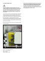
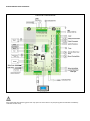
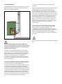
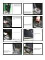
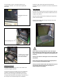
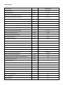
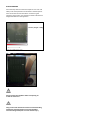
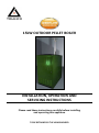
15kW OUTDOOR PELLET BOILER
INSTALLATION, OPERATION AND
SERVICING INSTRUCTIONS
Please read these instructions carefully before installing
and operating this appliance
TO BE RETAINED BY THE HOUSEHOLDER
CONTENTS
PAGE
INTRODUCTION
3
WARNINGS AND GAURANTEE / WARRANTY INFORMATION
4
SAFETY INSTRUCTIONS
4
OPERATING WARNINGS
5
GAURANTEE / WARRANTY INFORMATION
6
LIMITATIONS
6
EXCLUSIONS
6
PRE-INSTALLATION CONSIDERATIONS
7
PELLETS
7
CONSIDERATIONS FOR INSTALLATION
7
OPERATING AREA
7
CONNECTION TO THE FLUE
8
OPERATING PROBLEMS CAUSED BY DRAFT DEFECTS IN THE FLUE
PLUMBING PROBLEMS
INSTALLATION AND ASSEMBLY
8-9
10
10
UNPACKING
10
PREPARING THE BASE
11
ELECTRICAL CONNECTIONS
12
CONTROL PANEL SCHEMATIC
13
WATER CONNECTIONS
14 - 15
CONTROL SYSTEM
16
ERROR CODES
17 - 18
BOILER OPERATION AND MAINTENANCE
19 - 21
TECHNICAL DATA
22 - 23
BOILER HANDLING
24
SERVICE LOG
25
INTRODUCTION
Dear Customer,
We wish to thank you for choosing this Greenflame pellet boiler product from TR Engineering Ltd.
In order to get the best performance from your appliance we recommend that you read this booklet carefully before lighting
the appliance for the first time.
While thanking you again, may we remind you that the appliance MUST NOT be used by children, and that they must always
be kept at a safe distance from it!
Revisions to the publication
In order to improve the product, to keep this publication up to date the manufacturer reserves the right to make
modifications without any advance notice. Any reproduction, even in part, of this manual without the consent of the
manufacturer is prohibited.
Care of the manual and how to consult it
• Take good care of this manual and keep it in a place which can easily and quickly be reached.
• If this manual should be lost or destroyed, or if it is in poor condition, ask for a copy from your retailer or directly from the
manufacturer, providing product identification data.
• Information which is essential or that requires special attention is shown in bold text.
• Italic text is used to call your attention to other paragraphs in the manual or for any additional clarifications.
ATTENTION
This warning sign indicates that the message to which it refers should be carefully read and
understood, because failure to comply with what these notices say can cause serious damage
to the boiler and put the user's safety at risk.
INFORMATION
This symbol is used to highlight information which is important for proper boiler operation.
Failure to comply with these provisions will compromise use of the boiler and its operation will
not be satisfactory.
OPERATING SEQUENCES
Indicates a sequence of buttons to be pushed to access menus or to make adjustments.
MANUAL
Indicates that you should carefully read this manual or the related instructions.
The appliance must be connected to an electrical system
which is equipped with an earth conductor, as laid down in
directives 73/23 EEC and 93/98 EEC.
WARNINGS AND GUARANTEE / WARRANTY
INFORMATION.
The fuse must be of adequate rated capacity for the stated
electrical power of the appliance.
SAFETY INSTRUCTIONS
Installation of the boiler, making the electrical
connections, checking its operation, and maintenance are
all tasks which should be carried out by qualified and
authorised personnel.
Incorrect installation or faulty maintenance (not
conforming to the requirements set out in this booklet)
can cause harm to people, animals or property. In such
cases TR Engineering Ltd is absolved from any civil or
criminal responsibility.
Install the boiler in accordance with the regulations in
force in your local area, region and country.
For the correct use of the appliance and to prevent
accidents, the instructions given in this booklet must
always be followed.
Use, adjustment and programming must be carried out by
adults. Errors or incorrect settings may cause hazardous
conditions and/or poor operation.
Before beginning any operation, the user, or whoever is
preparing to operate on the appliance, must have read and
understood the entire contents of this instruction booklet.
All responsibility for improper use is taken entirely by the
user and such use relieves TR Engineering Ltd of any civil or
criminal responsibility.
Any kind of tampering or unauthorised substitution of nonoriginal spare parts can be hazardous for the safety of the
operator and relieves TR Engineering Ltd of any civil or
criminal responsibility.
Most of the surfaces of the appliance are extremely hot
(the boiler door, the handle, smoke discharge pipes, etc.).
Avoid coming into contact with these parts, without
adequate protective clothing or suitable implements such
as gloves with thermal protection or implements which
keep the hands cool.
Carefully explain this hazard to elderly people, disabled
people and particularly to all children, keeping them away
from the appliance while it is running.
Under no circumstances should the appliance be run with
the door open.
Do not touch the appliance with wet hands, in view of the
fact that it is an electrical appliance.
Before carrying out any cleaning or maintenance
operation, make sure in advance that the appliance is
isolated from the mains electricity supply, by removing the
mains isolator fuse.
Adhesives sealants and paints used in the manufacture of
the product are cured and present no known hazards when
used in the manner for which they were intended. The
appliance contains no asbestos
Always keep the cover of the fuel hopper closed.
OPERATING WARNINGS
Shut the appliance down in the event of a breakdown or
bad running.
Pellets must not be fed manually into the burner.
Accumulated un-burnt pellets in the burner after repeated
failed ignitions must be removed before re-lighting.
Do not wash the inside of the heat exchanger with water.
Do not wash the appliance with water. The water could get
inside the unit and damage the electrical insulation and
cause electric shocks.
Do not put any fuel, other than wood pellets, in the
hopper.
Install the appliance in a location which is suitable for firefighting, and equipped with all services such as air and
electricity supply and provision for discharging combustion
gases.
If there is a fire in the flue pipe, extinguish the appliance,
disconnect it from the power supply and never open the
door. Then contact the competent authorities.
If the appliance is in storage, it should be in a place that is
free of damp, and it should not be exposed to extremes of
temperature.
It is inadvisable to base the appliance directly on a floor (if
located indoors), and if the floor is made of flammable
material, it must be suitably insulated.
Do not light the appliance with flammable materials if the
ignition system breaks down.
INFORMATION
In case of any problems, get in touch with your dealer, or a
qualified engineer authorised by TR Engineering Ltd, and if
a repair is necessary, insist on the use of original spare
parts.
Use only the fuel recommended by TR Engineering Ltd
(ENplus-A1) may be used with this appliance.
Periodically check and clean the smoke outlet ducts
(connection to the flue pipe).
Accumulated un-burnt pellets in the burner after repeated
failed ignitions must be removed before lighting.
Keep this instruction manual carefully because it must stay
with the appliance throughout its working life. If the
appliance is sold or transferred to another user, always
make sure that the booklet goes with the product.
If it gets lost, ask TR Engineering Ltd or your authorised
dealer for another copy.
GUARANTEE CONDITIONS
TR Engineering Ltd offers the following warranties on this
appliance:
Leaks in the heat exchanger – 5 years
Faulty electrical components (motors, fan, controller) – 1
year
booklet, especially those concerning warnings on the
subject of installation, use and maintenance of the
appliance.
Damage caused by transport and/or handling is excluded
from the guarantee.
The guarantee will be invalidated in the event of damage
caused by tampering with the appliance, atmospheric
agents, natural disasters, electrical discharges, fire, defects
in the electrical system, and caused by lack of, or incorrect,
maintenance in terms of the manufacturer's instructions.
Pump, Ignition Element – 1 year.
CLAIMS UNDER THE GUARANTEE
From the date of first ignition of the appliance as proved
by a valid commissioning report which gives the name of
the Installer / Commissioning Engineer and the date on
which the commissioning took place. The guarantee is
conditional on the commissioning report being filled in and
returned to the manufacturer within 10 days, and requires
that the product be installed and commissioned by an
approved TR Engineering installer according to the detailed
instructions given in the instruction booklet supplied with
the product.
The term 'guarantee' is to be understood to denote the
free of charge replacement or repair of parts recognised to
have been defective at the start by reason of
manufacturing defects.
Limitations
The above guarantee does not cover parts subject to
normal wear such as gaskets, fibre board on doors and any
parts with can be removed from the firebox such as burner
pot, baffles and ash box. The replacement parts will be
guaranteed for the remainder of the guarantee period
starting from the date of commissioning of the product.
Exclusions
The warranty excludes all ancillary products associated
with the system (e.g. flue pipes, external circulation
pumps, bulk hoppers and augers, plumbing and electrical
system.). The warranty does not cover Third Party damage
to the product or damage caused by the plumbing (an
example would be an inappropriately sized expansion
vessel) or electrical system. Warranty does not cover
issues arising from pellets that do not conform to EnplusA1.
Recommendations advised to the Customer to be carried
out during commissioning must be completed and advised
to your local Dealer in order to validate the warranty.
The requirements for the flue installation, particularly in
relation to draught, is the responsibility of the system
owner. Compliance with Local Building Regulations must
be adhered to. The warranty does not cover misuse of the
product or sabotage.
Any consequential loss or damage caused by the failure
of a component on this product is not covered.
TR Engineering refuses to accept any responsibility for any
damage which may be caused, directly or indirectly, by
persons, animals or things in consequence of the failure to
observe all the prescriptions laid down in the instruction
The request for action under the guarantee must be
addressed to the Dealer / Retailer, who will forward the
claim to TR Engineering's technical assistance service. TR
ENGINEERING DECLARES THAT THE APPLIANCE WHICH
YOU HAVE PURCHASED COMPLIES WITH EEC DIRECTIVE
2004/108 EC and 2006/95/EC and SUCCESSIVE
AMENDMENTS.
TR Engineering refuses to accept any responsibility in the
event that the appliance or any other accessory has been
improperly used or modified without authorisation. For
all replacement of parts, only original TR Engineering
spare parts must be used.
Pre-Installation Considerations
therefore lead to the termination of the guarantee and of
the manufacturer's responsibility for the product.
Pellets
Wood pellets are manufactured by hot-extruding
compressed sawdust which is produced during the working
of natural dried wood. The compactness of the material
comes from the lignin which is contained in the wood
itself, and allows the production of pellets without the use
of glues or binders.
The market offers different types of pellet with
characteristics which vary depending on what mixture of
woods is used. The diameter varies between 6 mm and 8
mm, with a standard length in the range 5 mm to 30 mm.
Good quality pellets have a density which varies between
600 kg/m3 and 750 kg/m3, with a moisture content which
varies from 5% to 8% by weight.
Besides being an ecological fuel (exploiting timber residues
to the maximum and achieving cleaner combustion than is
possible with fossil fuels), pellets also have technical
advantages. While good-quality timber has a calorific
power of 4.4 kW/kg (with 15% moisture, therefore after
about 18 months' seasoning), the equivalent figure for
pellets is 4.9 kW/kg.
To ensure good combustion, the pellets must be stored in
an area that is free of humidity and protected from dirt.
The pellets are usually supplied in 10 kg bags, so storing
them is very convenient. Good quality pellets ensure good
combustion, thus lowering the emission of harmful agents
into the atmosphere.
The poorer the quality of the fuel, the more frequently
intervention will be necessary for cleaning the internal
parts, such as the grate and the combustion chamber.
The main certification of quality for pellets in the European
market is Enplus-A1 these ensure respect of:
Calorific power: 4.9 kW/kg
Water content: max 10% of weight
Percentage of ashes: max 0.5% of weight
Diameter: 6mm
Length: max 30mm
Contents: 100% untreated wood, with no added bonding
substances (bark percentage 5% max)
Packaging: in sacks made from ecologically compatible or
biologically decomposing material.
TR Engineering recommends using certified fuel in its
appliances to ENplus-A1 The use of fuel of inferior quality
or not conforming to the specification given above
compromises the running of your appliance and can
TR Engineering domestic pellet appliances run exclusively
on pellets with a diameter of 6 mm.
CONSIDERATIONS FOR INSTALLATION
IMPORTANT!
Installation and assembly of the appliance must be
carried out by qualified personnel.
The appliance must be installed in a suitable position to
allow the normal operations of opening and ordinary
maintenance.
The site must be:
Capable of providing the environmental conditions for
operation
Equipped with power supply 230V 50 Hz (EN73-23)
Capable of taking an adequate system for smoke discharge
Provided with external ventilation (if located indoors)
Provided with an earth connection complying with CEI 64-8
The appliance must be connected to a flue pipe or an
internal or external vertical duct conforming to current
standards UNI7129 - 7131 9615.
The boiler must be positioned in such a way that the
power isolation fuse is accessible.
IMPORTANT!
The boiler must be connected to a flue pipe or a vertical
duct which can discharge the fumes at the highest point
of the building.
The fumes are however derived from the combustion of
wood products, and if they come into contact with or
close to walls, they can cause smoke staining.
Also take care because the fumes are very hot and almost
invisible, and can cause burns on contact.
OPERATING AREA
For proper functioning, the appliance should be positioned
in a location where it is able to take in the air necessary for
combustion of the pellets (about 40 m3/h must be
available), as laid down in the standard governing the
installation and in accordance with local national
standards. All louvres on the external casing of the boiler
must be un-obstructed at all times as these allow air for
combustion and for cooling to enter the appliance
enclosure. Heavy snowfall can also obstruct the air in-take
louvres and cause the appliance to not burn clean. Smoke
emanating from the flue is a symptom of this. Snow must
be cleared from around the appliance at the earliest
opportunity.
CONNECTION OF THE FLUE
Where the appliance is to be installed indoors it is not
permissible to install the appliance where another
heating appliance is installed (fireplace, stove etc.) which
does not have its own independent air intake. Locating
the appliance in a room with an explosive atmosphere,
e.g. workshop or tool shed, is prohibited. The floor of the
room where the appliance is to be installed must be
strong enough to take its weight.
If the walls are not flammable, position the appliance with
a clearance to the rear of at least 45 cm. For flammable
walls, keep a minimum distance of 45 cm at the rear, 30
cm on the sides and 150 cm at the front.
TR Engineering recommends that the Therminox range of
stainless steel insulated flue pipe is used with this product.
A full range of straight, offset, elbow and ‘T’ elements is
available to overcome any obstruction which the flue
should avoid. The proper draught conditions in the flue is
critical for the efficient working of wood pellet boilers. The
flue can exit the boiler house/garage through the roof or
through the wall by using a bend on the flue. The
combustion chamber works in negative pressure. The
smoke duct for the discharge of fumes will also be under
negative when connected to an efficient flue pipe as
directed.
All sections of the flue must be capable of inspection and
removable to enable periodic internal cleaning.
If the flooring is made of wood, provide a floor protection
surface in compliance with current national standards.
Position the appliance bearing in mind all the instructions
and considerations above.
Service Clearances
The minimum service clearances around the appliance are
as follows:
Rear – 600mm
Side (lid hinge side) – 600mm
Side (lid open side) – 900mm
Front – 1200mm
IMPORTANT!
All 90 degree changes of direction in the flue pipe must
be either removable or capable of inspection.
THE FLUE PIPE RUN MUST NOT INCLUDE MORE THAN 2-3
METRES OF HORIZONTAL PIPE MUST AND NOT MORE
THAN THREE 90° ELBOWS (INCLUDING ‘T’s). IT IS ALSO
ADVISABLE NOT TO EXCEED 8 METRES IN LENGTH WITH
THE PIPE Ø 80 mm.
TR Engineering recommends the use of 80mm Therminox
flue for use with this appliance.
OPERATING PROBLEMS CAUSED BY DRAUGHT DEFECTS IN
THE FLUE
Of all the weather and geographical conditions which
affect the operation of a flue pipe (rain, fog, snow, altitude
a.s.l., exposure to sunlight, direction of facing), the wind is
unquestionably the most decisive. In fact, along with
thermal depression caused by the difference in
temperature inside and outside of the chimney, there is
another type of depression or over-pressure: dynamic
pressure caused by the wind. An updraft always increases
depression and hence draught. A crosswind increases
depression provided the cowl has been installed properly.
A downdraft always decreases depression, at times
inverting it.
Besides the direction and force of the wind, the position of
the flue and the cowl with respect to the roof of the
building and the surrounding landscape is important.
The wind also influences the operation of the chimney
indirectly by creating high-pressure and low-pressure
zones, not only outside the building but inside as well. In
rooms directly exposed to the wind (2), an indoor highpressure area can be created which can augment the
draught in boilers, stoves and fireplaces, but it can be
counteracted by the external high pressure if the cowl is
situated on the side exposed to the wind (1). On the other
hand, in the rooms on the opposite side from the direction
of the wind (3), a dynamic depression can be created
which competes with the natural thermal depression
developed by the chimney, but this can be compensated
for (sometimes) by locating the flue on the opposite side
from the direction of the wind (4).
IMPORTANT!
The operation of the pellet boiler is noticeably sensitive
to the conformation and position of the flue which is
adopted.
Hazardous conditions can only be overcome by suitable
setting-up of the boiler carried out by qualified TR
Engineering personnel.
PLUMBING CONNECTION
INSTALLATION AND ASSEMBLY
UNPACKING
IMPORTANT!
The GREENFLAME 15 Pellet Boiler will come packaged on a
single pallet. The flue will be packaged separately.
The connection of the boiler to the plumbing system must
be carried out ONLY by specialized personnel who are
capable of carrying out installation properly, in
compliance with current standards in the country of
installation.
If installation of the boiler will involve interaction with
another, pre-existing system complete with heating
equipment (gas boiler, methane boiler, fuel oil boiler,
etc.), it is even more advisable to call in qualified
personnel, who subsequently will be responsible for
conformity of the system with current applicable law.
TR Engineering will not be held responsible for damage to
persons or things in the event of failed or incorrect
operation if the aforementioned warnings are not
complied with.
The materials which make up the packaging are 100%
re-cyclable. Their storage or recycling is therefore the
responsibility of the final user, in compliance with local
regulations. Do not store the boiler without its packaging.
Remove the nylon strapping, cardboard packaging and
bubble wrap and recycle in the appropriate manner.
When unpacking the boiler use the checklist below to
ensure that all the required components to complete the
kit have been supplied. In the unlikely event of an omission
you must notify the manufacturer within 48 hrs of delivery.
The manufacturer reserves the right to charge for items
deemed lost after 48hr.
For connection of the plumbing system to the appliance,
the user should refer to chapter 4, INSTALLATION AND
ASSEMBLY; specifically, paragraph 4.5, CONNECTION TO
PLUMBING SYSTEM.
ITEM
LOCATION
Baffle Set – 3 Pieces
Combustion Chamber
Burner Pot
Combustion Chamber
User Manual Pack *
Combustion Chamber
Boiler Flue Support Brackets x 2
Hopper
Stainless Flue Support Brackets x 2
Hopper
Single – Twin Wall Flue Adaptor
Hopper
Flue 90° Elbow
Hopper
Rain Cap
Hopper
Flue Straight Lengths 1m x 2
Supplied In Separate Packaging
RECEIVED (YES / NO )
*The User Manual Pack includes a User Manual, Quick Step User Instructions, Commissioning Report, keys for
lockable doors and a heat proof glove.
PREPARING THE BASE
Careful planning at an early stage will greatly help the
installation process and make sure that all the required
clearances are adhered to for servicing and that any
potential issues with the routing of the flue can be
resolved.
The Greenflame pellet boiler should be positioned on a
concrete plinth at least 50mm high and should project a
minimum 100mm beyond the sides and the rear of the
appliance and at least 600mm to the front. The plinth must
be capable of supporting the weight of the appliance when
full with fuel and the plumbing system has been filled with
water.
Use the template below for constructing the plinth and for
positioning the flow and return pipe work and electrical
supply.
Refer to service and access clearances around the
appliance on Page *.
ELECTRICAL CONNECTIONS
Electrical installations should only be carried out by
suitably qualified and certified electricians. If in doubt on
any issue relating to the electrical connections on the
appliance contact TR Engineering Technical Support or
your local dealer for guidance before carrying out any
connections.
The Greenflame boiler must be supplied with a 230V 50 Hz
electrical supply via a two pole isolation switch rated for
Overvoltage Category III and protected with a 6A circuit
breaker. Also, the unit shall have a 30mA RCD installed into
the mains supply. It is recommended that a power
isolation switch is located adjacent to the boiler to isolate
the power during servicing and maintenance but also out
of the reach of children and to prevent accidental turning
off of the mains power.
Room thermostats shall be supplied / controlled by safety
extra low voltage.
Brown - Time Clock Control Live
Black – Permanent Live
Blue – Neutral
Green / Yellow – Earth
Only authorized TR Engineering personnel may open the
control panel on the boiler. Any interference with the
wiring in the control panel will invalidate the warranty.
The boiler and complete plumbing system must be
adequately earthed and bonded in accordance with local
Building Regulations and Bye- Laws.
BOILER CONTROL PANEL SCHEMATIC
Only authorised TR Engineering personnel may open the control board. Any tampering with the PCB will immediately
invalidate the warranty.
WATER CONNECTIONS
The diagram below indicates the plumbing connections at
the rear of the boiler. The return connection is factory
fitted with a 25/6 Standard pump
A non-return valve should be fitted to prevent backsiphonage.
Once the plumbing has been completed the system should
be fully flushed to clear any debris which may have
become lodged in the pipe work. The system should
generally be filled from the lowest point on the system to
force any air to the highest point where it can be vented.
The flow pipe on the boiler is fitted with a manual air vent
for venting air from the boiler. The system must then be
filled and the pump can be run continuously for a few
hours to completely de-aerate the system. Hold the ESC
button on the controller for 3 seconds to activate the
pump. Repeat the procedure to turn it off. Only when the
system has been fully vented can the boiler be
commissioned.
The installation and the design of the central heating
system must be in accordance with BS EN 14336:2004:
Heating Systems in Buildings. Installation and
commissioning of water based heating systems. BS EN
12828: 2003; Heating Systems in Buildings. Design of water
based heating systems. BS EN 12831: 2003: heating
systems in buildings. Method for calculation of the design
heat load.
Always ensure that all connections are making a watertight
seal.
Incorrectly sized expansion vessel will invalidate the
warranty. A minimum 18 litre vessels is recommended for
the boiler plus additional expansion for the heating and
domestic hot water system.
The boiler can be plumbed into either an open vented
system (the maximum static head of water permissible is
90 ft. (27.44 meters) or a sealed system. If plumbed into a
sealed system an appropriately sized expansion vessel
should be used and installed as per manufacturer’s
instructions. The expansion vessel should be sized based
on the water capacity in the boiler and the water in the
entire heating system.
The pump is on the return pipe work just before the boiler.
It is recommended that a by-pass pipe between the flow
and return is used with a valve to regulate the
temperature of the water returning to the boiler. Also, the
system designer should ensure that there is adequate
provision in the system for heat dissipation from the boiler
during the shut-down / extinguishing phase. An automatic
air vent and pressure relief valve must be fitted to the flow
pipe work immediately outside the boiler. The pressure
relief valve should be piped to a drain to prevent injury to
the User or Service Technicians if it is activated. All unused
connections should be sealed with blanking plugs.
CONTROL SYSTEM
FUNCTION
DESCIPTION
ON / OFF
Function: Ignition, Extinguishing by pushing the button for 3
seconds until the acoustic signal.
UNBLOCK
Function: Unblock. When the system is in Block by pushing
the button for 3 seconds until the acoustic signal.
MODIFY VALUES INTO MENU
In modify mode change menus and submenus values.
RUN ON MENU AND SUBMENU
In menu run on submenu and menu.
ESC
Function: Exit managed pushing the button if in a menu or a
submenu. Out of menu “Pump Test”.
MENU
Function: Enter in menu or in a submenu.
MODIFY
Enter in modify mode into a menu.
SET
Save data in a menu.
ENABLE CHRONO PROGRAMMING
In Chrono menu – Chrono Program: enables the selected
program.
KEYBOARD LOCK
To lock keyboard keys keep this button pressed for 3
seconds. To unlock repeat the same procedure.
BUTTON
P2
P4
P6
P1
P3
P5
ERRORS
DESCRIPTION
DISPLAY
Error activation safety thermostat high voltage.
Er01
Error activation pressure switch (only with the exhaust fan on).
Er14
Accidental extinguishing for low exhaust temperature.
Er03
Water over-temperature.
Er04
Exhaust over-temperature.
Er05
Encoder error.
Error can occur for lack of encoder signal.
Er07*
Encoder error.
Error can occur in case of adjustment problems of rounds number.
Er08*
Water pressure low.
Er09
Water pressure high.
Er10
Real time clock error.
Er11
Ignition failed.
Er12
Lack of voltage.
Er15
Air flow regulator error.
Er17
Extinguishing from lack of pellets.
Er18
Burner cleaning system fault.
Er33
*Only for product with encoder.
ERROR CODES
In the unlikely event that the appliance fails to start or shuts down unexpectedly, then the Error code show on the display
will give an indication as to the potential cause of the problem. Some of the errors can be cleared by the house holder and
they are.
Er01 - Water Safety Thermostat – Press the reset button A and then hold button B for three seconds to clear the error from
the controller.
Er03 - Accidental Extinguishing for Low Exhaust Temperature – Empty any un-burnt pellets from the burner pot and hold
button B for three seconds.
Er04 - Water over temperature – Hold button B for three seconds. If the problem persists contact you service agent.
Er12 - Failed Ignition– Empty any un-burnt pellets from the burner pot and hold button B for three seconds.
Er15 - Loss of Voltage– Usually occurs after a power-cut. Empty any un-burnt pellet from the burner pot and hold button B
for three seconds.
Er18 – Lack of Pellet – When the pellets reach the pellet sensor in the hopper the system extinguishes to prevent having to
re-prime the auger.
Other errors can appear on the display but these may only be cleared by service personnel.
BOILER OPERATION & MAINTAINANCE
The Greenflame has been developed to ensure that the
user is able to carry out the most basic functions in a safe
and convenient manner. Once the installation has been
successfully carried out the user interaction is quiet simple
from a regular inspection on the combustion chamber to
remove ash to filling the hopper with pellets.
Turning ON and OFF the boiler
It is recommended that your boiler is controller by an
external time clock. The time programs should be set to
the times that heat is required at different periods
throughout the day. You should also make allowance for
the ignition time of the appliance, i.e. the time it takes
from when the time clock signals the boiler to start until
the flame has fully developed in the appliance (usually
approx. 10-20 minutes).
When choosing your programs on your time clock it is
recommended that you program the clock for long runs
instead of short runs. This gives the boiler time to settle
and match the heat demand of the property. It is also
when the boiler is most efficient.
If the boiler is not being controlled by a time clock then it
can be turned on and off locally at the display on the boiler
control panel. Hold the ON/OFF button for 3 seconds to
start the boiler. Hold the ON/OFF button for 3 seconds to
turn off the boiler.
Emptying the Ash Pan
The boiler contains two areas where ash needs to be
removed at regular intervals.
The primary ash pan is located in the main combustion
chamber. The frequency of emptying the ash pan is
determined by the length of time the boiler has been
running and under what load conditions. Once the ash in
the ash pan has reached the top then it should be emptied.
A daily check during the first few days of operation will
give an indication as to when it needs to be emptied.
Always make sure that before you open the main
combustion chamber door that the boiler has been
switched off as has been allowed to cool down
sufficiently so as not to cause injury.
Always empty ash into a metal container as ash which
may appear cool could be hot in the centre.
Never use plastic brushes or dust pans to clean ash from
the boiler.
Always use heat resistant gloves when handling the ash
pan or cleaning the boiler.
When the combustion chamber door is opened, even
with the boiler in the OFF position, the combustion fan
will run at full power.
The secondary ash pan is located under the main
combustion chamber. This needs to be emptied less
frequently.
emptied. A daily check during the first few days of
operation will give an indication as to when it needs to be
emptied.
Filling With Fuel
The boiler will indicate when the level of pellets reaches a
low level. The system will shut down and will wait for the
hopper to be refilled.
Open the pellet hopper lid and carefully pour approved
pellets into the hopper.
Never fill the hopper above the guard mesh across the
opening of the hopper.
Never allow any foreign material to enter the hopper.
This will lead to the malfunction of the auger system and
could cause damage to the appliance and invalidate your
warranty.
Always close the lid to the hopper once it has been filled
with pellets.
Never leave the hopper lid open for prolonged periods
as rain or moisture can affect the pellet.
Emptying the Ash Pan
The boiler contains two areas where ash needs to be
removed at regular intervals.
The primary ash pan is located in the main combustion
chamber. The frequency of emptying the ash pan is
determined by the length of time the boiler has been
running and under what load conditions. Once the ash in
the ash pan has reached the top then it should be
Always supervise children when the hopper lid is open in
case foreign material is placed into the hopper or
children climb into the hopper.
TECHNICAL DATA
Technical data
Nominal output
GREENFLAME
kW
4.8 – 16.1
Kg/hr
1 – 3.5
Efficiency nominal Output (EN 303-5)
%
90.7
Smoke Temperature at Nominal Power
°C
130 - 150
Smoke Temperature at Reduced Power
°C
70 - 90
Minimum Required Draft
Pa
10
Exhaust Gas Mass Flow
g/s
6 - 11
CO2 at Reduced and Nominal Power
%
6 - 12
Water Operating Temperature Range
°C
50 - 85
Bar/kPa
3 / 269
Recommended Operating Pressure
bar
1.5
Water Flow Connection
mm
22mm
Water Return Connection
mm
22mm
Boiler Drain
inch
1/2"
Boiler Safety Thermostat Setting
°C
105
Frost Thermostat Adjustable Between 4 & 10
°C
Factory Set at 4
Class
Class 3
Nominal Fuel Input
Maximum Operating Pressure
Boiler Class
Boiler Electrical Power Requirement
230V 50Hz
Maximum Electrical Consumption
Watts
< 500
Average Electrical Consumption in Normal Running
Watts
164
Line Voltage Fuse Protection
Amp
6
PCB Fuse Protection
Amp
1
Width
mm
600
Height
mm
1100
Length (Excluding Flue)
mm
920
kg
110
mm
80
kg
160
litres
18
Fuel Hopper Capacity
Boiler Flue Diameter (I.D)
Boiler Dry Weight
Water Content
BOILER OPERATION AND MAINTENANCE
BOILER HANDLING
One of the key features of the E-Compact 15 is its size and
ability to be transported to and located in confined spaces.
Care should also be exercised when manoeuvring the
appliance into position. The illustration below indicates the
weight distribution of the appliance.
Always protect the appliance when transporting on
trollies or hand carts.
Only persons who have been trained in manual handling
techniques should attempt to move the appliance.
Incorrect lifting techniques can cause serious injury.
SERVICE LOG
DATE
SERVICE PROVIDED
SERVICE
ENGINEER
DATE
SERVICE PROVIDED
SERVICE
ENGINEER
DATE
SERVICE PROVIDED
SERVICE
ENGINEER
DATE
SERVICE PROVIDED
SERVICE
ENGINEER
DATE
SERVICE PROVIDED
SERVICE
ENGINEER
DATE
SERVICE PROVIDED
SERVICE
ENGINEER
DATE
SERVICE PROVIDED
SERVICE
ENGINEER
TR ENGINEERING LTD
UNIT 7, NEWTON CHAMBERS WAY
THORNCLIFFE INDUSTRIAL ESTATE
CHAPELTOWN
SHEFFIELD
S35 2PH
Tel: (0114) 2572300
Fax: (0114) 2571419
www.trianco.co.uk
© TR Engineering Limited
Copyright in this brochure and the drawings and illustrations contained in it is vested in TR Engineering Limited and neither the brochure or any
part thereof may be reproduced without prior written consent.
TR Engineering Limited's policy is one of continuous research and development. This may necessitate alterations to this specification.
February 2012
Item No. 400001 Iss. 1