1
845S Mainboard Series
User’
User’s Manual
SOCKET 478 SDR ATX Mainboard
845S845S-AV
Version 3.x
UM-845S-AV-E2
Rev 3.0V
Creation Date: 31 December 2002
845S-AV MAINBOARD
Ver 3.x
Page 1
User’s Notice
!""
#
#$%&$ ' () ' (* #
+,-.
,
-!
-!$,
&
/
• #
• 0
• &,%1
• &2.
• &%0+%
, , 3 4
Page 2
845S-AV MAINBOARD
Ver 3.x
Table of Contents
!"
#
$!!% #
$!!&"'! (
$!! )*&
+&
,
&-.+
)*! !"#$ % $# &'$(&))'*")$
+
$
!&
,-
**.(-+ ,
,$)
#
)
,
,#$#"-#
)
,
,&/0$
%**#
)
,,12(1.323&4+#
)
,#&%
5&03 56
3 #
)
7
,78#
)
7
-!/)0&
1
$19$
252!!:%*)"#
)
;
#
)
;
<8%
#
)
;
2'
-
)0&
#
7*.#
)
7-
$$
#
)
845S-AV MAINBOARD
Ver 3.x
Page 3
Table of Contents
1)*
!&
#
;$5=
#
)
;$5
%#
)
;#2#2#
)
;$$
#
)
>
;,88$
>
;&%
'$
#
)
>
#,
% (
?$9=
5
%$
2 ?$9#$-8#
).*)
?$9#$
;?$9##2 34350/$&.! & 3/$
3&"
2
$%
-
"
! #
2 -
% 1 -6-7-&$&%
# -& !" ( 879!%&
! 2
:0! 1
-
#
.
-
(
39);)<$=)=.-7)<$=4$= .=39$6> Page 4
845S-AV MAINBOARD
Ver 3.x
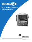
Introduction
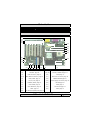
(17)
(16)
(15)
(14)
(13)
(12)
(18)
(19)
(20)
(21)
(22)
(11)
(23)
(10)
(9)
(8)
(1)
(7)
(6) (5)
(4)
(3)
(2)
(1)
DIMM1, DIMM2, DIMM3 page 13
(13)
WOL Connector. page 16
(2)
AGP Slot. page 14
(14) (15)
AUX-IN / VIDEO-IN page 17
(3)
FDD Connector. page 15
(16)
CD-IN page 17
(4) (5)
IDE1,IDE2 Connectors. page 15
(17)
PC99 ATX connectors page 19
(6)
USB3, USB4. page 17
(18)
KB/MS PWR-ON page 21
(7)
PW, HL, RS. page 18
(19)
Power Supply Connectors page 16
(8)
PWRLED, SPKR. page 19
(20)
JPU FSB page 21
(9)
Clear CMOS. page 21
(21)
FAN2 page 15
(10)
Clear Password. page 21
(22)
CPU Socket page 13
(11)
FAN3. page 15
(23)
FAN1 page 15
(12)
PCI1,PCI2,PCI3,PCI4,PCI5 page 14
845S-AV MAINBOARD
Ver 3.x
Page 5
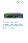
Introduction
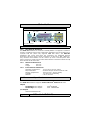
PC99 ATX Connectors
CN2: PS2 Mouse
CN18: Game/Midi
CN5: LPT
CN7: USB2
CN6: USB1
CN3: COM1
CN4: COM2
CN1: PS2 Keyboard
SPK OUT
MIC
LINE IN
!!"
1.2.1. The 845S-AV Mainboard
The 845S-AV mainboard is a Pentium™ 4 SDR platform. It supports a maximum
memory of 2GB and comes with 4 USB ports. Onboard it has six PCI slots and a
1x/2x/4x AGP slot (which only supports 1.5V AGP cards). The 845S-AV
mainboard also comes with three fan connectors (for additional thermal
protection) and three power supply connectors. It also has a WOL (Wake-OnLan) connector that enables it to be “woken up” from a soft-off power state
when it receives a signal from the LAN. Other onboard connectors include Aux-IN,
Video-IN and CD-IN connectors.
1.2.2.
Mainboard Dimensions
Width
305 mm
Length
200 mm
1.2.3.
Environmental Limitations
Operating Temperature:
10°C to 40°C (50°F to 104°F)
Required Airflow:
50 linear feet per minute across the CPU
Storage Temperature:
-40°C to 70°C (-40°F to 158°F)
Humidity:
0 to 90% non-condensing
Altitude:
0 to 10 000 feet
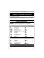
Processor
The 845S-AV mainboard supports Socket 478 Intel® Pentium™ 4 CPUs.
Chipset
Northbridge Core Chipset:
Southbridge Core Chipset:
Intel® RG82845
Intel® FW82801BA
I/O Chipset
Winbond W83627HF-AW
Page 6
845S-AV MAINBOARD
Ver 3.x
Introduction
CPU Switching Voltage regulator
This mainboard is equipped with a switching voltage regulator that automatically
detects a DC power supply from +1.10V to +1.85V.
System Memory
The mainboard has three 168-pin DIMM modules onboard. These modules are
able to support 3.3V PC-133 SDR SDRAM modules. A maximum memory of 3GB
is supported.
Expansion Slots
The 845S-AV mainboard are equipped with six dedicated PCI slots and one
(1.5V) 1x/2x/4x AGP slot.
Onboard Audio Features
Supports Microsoft DirectSound/ DirectSound 3D and AC97 Full Duplex.
Word Size
• Data Path:
•
8-bit, 16-bit, 32-bit, 64-bit
Address Path:
32-bit
Front Side Bus Frequency (FSB)
For a P4 Socket 478 CPU 533 / 400 MHz FSB (133 / 100 MHz QDR) is supported.
BIOS
•
•
•
•
Award BIOS, Windows 95/98 Plug and Play (PnP) compatible.
Supports SCSI sequential boot-up.
Flash EPROM for easy BIOS upgrades.
Supports DMI 2.0 function
Desktop Management Interface (DMI)
The mainboard comes with DMI 2.0 built into the BIOS. The DMI utility in the
BIOS will automatically record different information about your system configuration and store this information in the DMI pool, which is a part of the system
board's Plug and Play BIOS. DMI, along with the appropriately networked software, is designed for easy inventory, maintenance and the simplified troubleshooting of computer systems.
WOL (Wake-On-LAN) Port
One WOL connector supports Wake-On-LAN functionality.
USB Ports
USB allows data exchange between your computer and a wide range of simultaneously accessible external Plug and Play peripherals. The 845S-AV mainboard
is equipped with four USB (version 1.1) connectors. USB 1 and USB 2 are external connectors. They can be found on the PC 99 ATX connector. The other USB
connectors are internal connectors and can be used to connect other USB devices. (Cables for the internal connectors are sold separately).
845S-AV MAINBOARD
Ver 3.x
Page 7
Introduction
!
"
Connectors
• Two IDE connectors.
•
•
•
•
•
•
•
•
One floppy drive interface supports up to two 2.88MB floppy drives.
One 20-pin ATX power supply connector.
One 4-pin (2x2) 12V ATX power supply connector
One 4-pin (1x4) ATX Auxiliary power supply connector
One CPU fan and two chassis fan connectors.
One CD audio-IN connector.
One Video-IN connector.
One Aux-IN connector
ATX Double Deck Ports (PC 99 color-coded connectors)
• Two USB ports.
•
•
•
•
•
•
Two external DB-9 serial port connector: COM 1 and COM 2 (UART).
One SPP/ECP/EPP DB-25 parallel port.
One mini-DIN-6 PS/2 mouse port.
One mini-DIN-6 PS/2 keyboard port.
One game/MIDI port.
Three audio jacks: speak-out, line-in and mic-in.
PCI Bus Master IDE Controller
• Two PCI IDE interfaces support up to four IDE devices.
•
•
•
•
Page 8
The 845S-AV mainboard supports ATA/33, ATA/66 and ATA/100 hard
drives.
PIO Mode 3 and Mode 4 Enhanced IDE (data transfer rate up to
16.6MB/sec.).
Bus mastering reduces CPU utilization during disk transfer.
Supports ATAPI CD-ROM, LS-120 and ZIP.
845S-AV MAINBOARD
Ver 3.x
Introduction
#$%&'(
The mainboard is capable of monitoring the following health conditions of your
system:
1. Processor temperature. It has an overheat alarm.
2. VCORE/3.3V/5V/12V/-12V voltages and failure alarm.
3. Processor and chassis fan speeds. It has a failure alarm for these fans.
4. Read back capability that displays temperature, voltage and fan speed.
1.4.1. Hardware Monitoring System Utility
The mainboard comes with the Hardware Monitoring System utility contained
on the CD. It is capable of monitoring the systems hardware conditions such
as the temperature of the processor, voltage, and the speed of both the CPU
and chassis fans. You are allowed to manually set a range to the items being
monitored. We recommend that you use the Default Settings, which are the
ideal settings that will maintain the system in a good working condition.
1.4.2. Installation
To install this utility, please insert the CD into the CD-ROM drive. The auto run
screen (Driver Utility) will automatically appear. Click the Hardware Monitoring
button, choose the chipset, model number and the OS that is installed. Please
refer to the CD “Readme” file for further installation instructions.
Note: Only use this utility in Windows operating systems.
)$%''*
Dual Function Power Button
Depending on the setting in the Soft-Off By Power-Button field of the Power
Management Setup, this switch allows the system to enter the Soft-Off or
Suspend mode.
RTC Timer to Power-on the System
The RTC installed on the system board allows your system to automatically
power-on at a set date and time.
Wake-On-LAN Ready
The Wake-On-LAN function allows the network to remotely wake up a Soft
Power Down (Soft-Off) PC. Your LAN card must support the remote wakeup
function. The 5V SB power source of your power supply must be at least
720mA.
ACPI Ready
The mainboard is designed to meet the ACPI (Advanced Configuration and
Power Interface) specification. ACPI has energy saving features that support
OS Direct Power Management (OSPM) for round the clock PC operation.
845S-AV MAINBOARD
Ver 3.x
Page 9
Hardware Installation
''+(,'
The following is a checklist of all the expansion slots, jumpers and connectors
that should be configured on your mainboard before you can run your pc.
Installation Checklist
Expansion Slots and Sockets
CPU Slot
DIMM Slots
PCI Slots
AGP Slot
Socket 478 CPU Slot which supports Pentium 4
Three 168 pin slots that support up to 3GB of SDRAM.
Six 32 bit PCI Slots.
One Accelerated Graphics Port Slot
Internal Connectors
CN8
CN9
CN10
CN13
CN15-A
CN15-B
CN15-C
CN16
CN17
CN21
CN27
CN30
CN31
CN44
CN45
Floppy Disk Drive
Primary IDE
Secondary IDE
CPU Fan
ATX Power Supply
ATX 12V Power Supply
Auxiliary ATX 12V Power Supply
Wake On Lan
Chassis Fan 1
CD Audio In
Chassis Fan 2
Universal Serial Bus 3
Universal Serial Bus 4
Video In
Auxiliary In
FDC
IDE1
IDE2
Fan 1
ATX
ATX12V
AUX
WOL
FAN2
CD-In
FAN3
USB3
USB4
Video-IN
Aux-IN
External Connectors
CN1
CN2
CN3
CN4
CN5
CN6
CN7
CN18
Page 10
PS/2 Keyboard Connector
PS/2 Mouse Connector
Serial Port 1
Serial Port 2
Parallel Port
Universal Serial Port 1
Universal Serial Port 2
Game/Audio Port
PS/2 KB
PS/2 MS
COM1
COM2
LPT
USB1
USB2
Audio/Game
845S-AV MAINBOARD
Ver 3.x
Hardware Installation
Installation Checklist (Continued)
System Panel Buttons and LED Connectors
PW
HL
RS
Power On/Off and Suspend Switch Connector.
HDD LED Connector
Reset Button Connector
-45?)0
-@
$
*.#
)
,-
,-
,-
,-
=85$1<324
#$-8#
).)
#$
##2
''
You need to complete the following installation steps before you use your PC.
• Check and set the mainboard settings.
•
•
•
•
•
Install the Central Processing Unit (CPU).
Install the memory modules.
Install the expansion cards.
Connect the ribbon cables, panel wires and power supply.
Setup the system BIOS
Note: Before you start installing your mainboard we strongly recommend that you use a
grounded anti-static mat. We further recommend that you attach an anti-static wristband, which is grounded at the same location as the mat to your wrist.
845S-AV MAINBOARD
Ver 3.x
Page 11
Page 12
845S-AV MAINBOARD
Ver 3.x
" !
# " ! $ % % &
# " ! $ % % & ! " Hardware Installation
-.+/+0%
Hardware Installation
#+1/%$-.'
2.4.1. Installation of the CPU
To install your processor, please complete the following set of instructions
1. Locate a small dot marked on the top of the CPU. This mark indicates
Pin 1 of the CPU.
2. Locate Pin 1 for the Socket on the mainboard.
3. There is a lever on the side of the socket. First push this lever sideways
and then lift it to a 90-degree angle.
4. Insert the CPU into the Socket. Please make sure that Pin 1 for the CPU
is inserted into Pin 1 of the Socket.
5. When the CPU is installed correctly push the lever back into place.
6. Install a proper heat sink with cooling fan for proper heat dissipation. Failing to install a heat sink with cooling fan may cause overheating which will burnout your CPU and damage your mainboard.
IMPORTANT: CPU COOLING FAN
Please ensure that you have an approved heat sink with cooling fan. Without a proper
heat sink with cooling fan you will damage both the mainboard and the CPU.
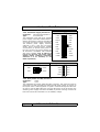
2.4.2. Memory Modules
The mainboard has three 168-pin SDR SDRAM slots. The SDR SDRAM slots are
located on the right hand side of the board. To install the DIMM’s into these
slots, make sure the white lever at each side of the slot has been pulled down to
an angle of approximately 45. Make sure that the DIMM is in the correct orientation. Place the DIMM on the slot and push down firmly.The white levers will come
back up and lock the module in place.
These mainboards support 133MHz SDR SDRAM. SDR SDRAM memory devices
with densities of 64Mb, 128Mb, 256Mb and 512Mb technology x8 or x16 are supported by the Intel 845 chipset memory interface. Three double sided DIMMs
with unbuffered PC133 can be supported. A maximum memory bandwidth of
1GB/s is possible with PC133.
Top View of a 168-pin DIMM Slot
10 Pins
30 Pins
44 Pins
Important: The DIMM’s can only be fitted into the slots in one orientation.
Make sure that the DIMM’s are in the correct orientation and the pins are correctly aligned before you insert them.
845S-AV MAINBOARD
Ver 3.x
Page 13
Hardware Installation
6=)AB
C)
%
!
%"
",8
!<&%)
!1
3
% @ 1
; )
@ 1
; 1
, % :3
*)
*
/
*
!"*
%
%
32 " % % 1
" )
*% * *
"1
/""*
%
"*
9
+ <%)"
%
!
6))"%
,8
":3
-#)""!
+ "#
!%
%)"
%
!
1
%
,8
+ <%)"
%)
*%
,8
/"*
)
))%!&)'*")$
(&'$+
*%
2.4.3. PCI Slots
The mainboard comes with three PCI slots. They are located on the left hand
side of the board. Both PCI and PCI expansion cards may require IRQ’s. This
mainboard complies with Plug and Play (PnP) specifications. Whenever a PnP
compliant card is added the system will automatically be configured and the
IRQ’s will be assigned automatically. When you are inserting your PCI card
make sure that the pins are correctly aligned. When the pins are properly
aligned with the hole’s in the slot, push down gently.
Top View of a 32-bit PCI Slot
#
2.4.4. AGP Slot
AGP (Accelerated Graphics Port) is a dedicated bus slot. It operates at 66 MHz
and transfers data at a rate up to 1066 MB/s. This allows 3D applications to
run more smoothly. The mainboard comes with a 1.5V AGP slot. This slot is
able to support 1x/2x and 4x (1X is 266 MB/s, 2X is 533 MB/s; and 4X provides 1066 MB/s) AGP cards.
Top View of an AGP Slot
Page 14
845S-AV MAINBOARD
Ver 3.x
Hardware Installation
)'+
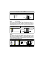
2.5.1. Floppy Disk Connector
Connector:
CN8 (FDC)
Type:
34 pin block
The FDC connector can support two floppy drives. It is located at the front of
the mainboard. To connect, use the ribbon-cable that has been provided.
Make sure that the red strip is connected to PIN 1 of the connector.
Top View of a Floppy
Disk Drive Connector
$ 4
2-
2.5.2. Primary and Secondary IDE connectors
Connector:
CN9 (IDE1)/CN10 (IDE2)
Type:
40 pin block
The mainboard has two IDE connectors: a primary and secondary. Each IDE
connector can support two IDE drives. These mainboards can therefore support up to four IDE devices each. If you install two hard drives, you need to
configure the second drive to slave mode in the BIOS setup. Please refer to
your hard drive manual for the appropriate jumper settings.
PIN 1
Top View of an
IDE Connector
20 PINS
2.5.3. CPU Fan and Chassis Fan Connectors
Connector:
CN13 (FAN1)/CN17 (FAN2)/CN27 (FAN3)
Type:
3 pin
The cooling fans must be connected to their respective power connectors. If
you have installed the hardware-monitoring feature you will be able to monitor
the rotating speed of the CPU cooling fan in your Windows operating system.
Front View of a Fan Connector
+12V DC
Fan Signal
Ground
Top View of a Fan Connector
+12V DC
Ground
1
Fan Signal
2 3
845S-AV MAINBOARD
Ver 3.x
Page 15
Hardware Installation
ATX Power Supply Connector
2.5.4. ATX Power Supply Connectors
Connector:
CN15-A/CN15-B/CN15-D
Type:
2x10/2x2/1x4
The mainboard comes with three onboard
power supply connectors labeled CN15-A,
CN15-B and CN15-D. CN15-A and CN15-B
are regular ATX power supply connectors.
The auxiliary power supply connector
(CN15-D) is for a +12V and +5V power
supply. These increased power supplies
are necessary to provide extra power for
the slot. The ATX 12V power supplies are
all downward compatible with standard
ATX power supplies. Plug in CN15-D as
long as you find out your power supply
without ATX12 (CN15-B) connection.
Otherwise it is no necessary to use
CN15-D (AUX12V).
ATX12V Power Supply Connector
COM
+12VDC
COM
+12VDC
+12VDC
+5VDC
+5VSB
+5VDC
PWR_OK
-5VDC
COM
COM
+5VDC
COM
COM
COM
+5VDC
PS_ON#
COM
COM
+3.3VDC
-12VDC
+3.3VDC
+3.3VDC
Pin 1 Pin 11
Auxiliary Power Supply Connector
Pin 1 Pin 3
+5VDC
Pin 4
COM
Pin 3
COM
Pin 2
+12VDC
Pin 1
2.5.5. WOL (Wake-On-LAN) Connector
Connector:
CN16
Type:
3 pin
The mainboard has a WOL (Wake-On-LAN) connector. This connector must be
connected to a LAN card that has Wake-On-LAN (WOL) output. It powers up
the system when a wakeup packet or signal is received through the LAN card.
In order to use the WOL LAN card to trigger the power on the PC system, the
switching power supply must have the ability to provide a driving current of at
least 720 mA and be connected to a “5V standby” voltage.
Page 16
845S-AV MAINBOARD
Ver 3.x
Hardware Installation
Top View of a WOL Connector
Front View of a WOL Connector
Ground
1
5V_SB
2
Ground
3
WOL
WOL
5V_SB
2.5.6. CD-IN/AUX-IN/VIDEO-IN Connector
Connector:
CN21 (CD-IN)/CN44 (VIDEO-IN)/CN45 (AUX-IN)
Type:
4 pin un-housed
This mainboard has one CD-IN connector, AUX-IN connector. The CD-IN connector is used to connect the CD ROM audio out and allows the system to receive audio input from the CD ROM. The AUX-IN connector allows the system to
receive signals from other audio devices like a radio or tape. The VIDEO-IN
connector allows you to receive signals from devices like TV tuners, Video machines and Video cameras.
Top View of a CD/AUX-IN
& VIDEO-IN Connector
1
2
3
4
Front View of a CD/AUX-IN
& VIDEO Connector
Left Channel
CD/AUX/VIDEOIN
Left Channel CD/AUX/VIDEO-IN
Ground
Ground
Right Channel CD/AUX/VIDEO-IN
Right Channel
CD/AUX/VIDEOIN
Ground
Ground
2.5.7. USB Connectors: USB3 and USB4
Connector:
CN 30 (USB3)/ CN 31 (USB4)
Type:
5 pin
This mainboard comes with 2 extra onboard USB ports. Ribbon cable for these
four connectors are optional. These connectors allow you to connect 2 extra
USB devices to the mainboard. It should be noted that these USB connectors
are non-standard and the cable you purchase should therefore have, on one
side, a connector which is compatible with the on-board USB connector and on
the other side a standard USB connector.
Ground
5
1
5V DC
Ground
4
2
Data-
Data+
3
3
Data+
Data–
2
4
Ground
5V DC
1
5
Ground
Front View of a USB Port
USB 3
USB 4
Top View of a USB Port
Data +
Ground
Data -
Ground
5V DC
845S-AV MAINBOARD
Ver 3.x
Page 17
Hardware Installation
2$%1'-+
The following System Panel Buttons and LED
Connectors (2 x 3 pins) can be found at the
front of the mainboard on the left hand side.
$ 4
Top View of the System Panel
and LED Connectors
PW= Power On/Off and Suspend Switch Connector
HL = HDD LED Connector
RS = Reset Button Connector
2.6.1. PW: Power On / Off and External Suspend Switch Connector
The Power On/Off connector has two functions. It can be the Power Switch or
Suspend Switch of your PC system. You can either choose “Delay 4 Sec” or
“Instant OFF” (Please refer to the BIOS setup instructions in Chapter 3).
Option 1: If you choose “Delay 4 Sec.” In the BIOS CMOS Setup, the function of “PW” will be:
A. When the system power is "OFF", press this switch, the system will
power on.
B. When system power is "ON”, you can select two different modes: Mode 1: Press and hold the Power ON button for less than 4 seconds and then
release it. The system will be turned into Suspend mode (turned into the
GREEN mode) When the system is in the Suspend mode:!
Press the Power on button (less than 4 seconds), the system will return
to Full-ON mode.
!
Press and hold the Power On Button for more than 4 seconds, the
system will be powered off.
Mode 2: Press and hold the Power ON button for more than 4 seconds, the
system will be completely powered off.
Option 2: If you choose “Instant OFF.” In the BIOS CMOS Setup, the power
switch will operate like a normal ON / OFF Power button.
2.6.2. HL: HDD LED Connector
Any read and write activity by the HDD will turn this LED on.
2.6.3. RS: Reset Button Connector
If you connect this connector, you will be able to reset you computer by pressing the reset button at the front of the chassis.
Page 18
845S-AV MAINBOARD
Ver 3.x
Hardware Installation
3,1"-+
2.7.1. Speaker Connector
Connect your chassis speaker to this
four pin connector. It allows you to
hear systems beeps and warnings PIN 1
sound.
PIN 1
2.7.2. Front Panel Power LED
The chassis Power LED connector can
be connected to the four pin
connector. When you turn your
system on, this LED will also be
turned on.
SPEAKER
+5V DC
Speaker Speaker Speaker
Signal
Signal
Signal
+5V DC
NC
Ground
NC
POWER LED
Top View of the Speaker
and Power LED Connector
4-.'+
2.8.1. PS/2 Keyboard connector.
Connector:
Type:
CN 1
6 pin female
This connector only supports a PS/2 keyboard plug. If you have a standard AT
size (large DIN) keyboard plug, you need to use a mini DIN adapter.
2.8.2. PS/2 Mouse Connector.
Connector:
Type:
CN 2
6 pin female
This connector only supports a PS/2 mouse plug. If a PS/2 mouse is detected then IRQ 12 will be directed to CN 2.
2.8.3. Serial Port 1 (COM 1) and Serial Port 2 (COM 2)
Connector:
Type:
CN 3 (COM 1)
9 pin male
One serial port is available for a mouse and
other serial devices. (I/O addresses used
are 3F8H/2F8H/3E8H/2E8H and IRQ3/IRQ4,
selected by CMOS setup.)
COM 1
845S-AV MAINBOARD
Ver 3.x
COM 2
Page 19
Hardware Installation
2.8.4.
Parallel Port Connector (LPT)
Connector:
Type:
CN 5
25 pin female.
This parallel port is used by printers
which support the SPP, EPP and ECP
modes IRQ7 or IRQ5 can be selected. The ECP mode will use either
DMA 3 or DMA 1 (which can be selected by the BIOS setup program).
2.8.5. Universal Serial Bus (USB) Port 1 & 2
Connector:
Type:
CN 6 (USB 1)/ CN 7 (USB 2)
4 pin female
Two USB ports are available for connecting
USB devices. The mainboard is also
equipped with an expansion connector that
supports two additional USB external
connectors. (The USB cable is not included
with the mainboard).
USB 2
USB 1
2.8.6. Audio/Game Port Connector
Connector:
Type:
SPK-OUT
LINE-IN
MIC-IN
CN 18
15 pin female
The Game/MIDI port connector is a
dual purpose connector. It can either
be used to connect a joystick to the
computer for game participation, or it
can be used to attach an external
MIDI device. All these motherboards
have 3D audio interfaces onboard.
50%*
Jumpers are built on the mainboard to allow the user flexibility to configure the
mainboard settings to meet their specific requirements. When there is no
jumper cap inserted into the jumper it is called “OPEN.” When a cap is inserted
into the jumper it is known as a “SHORT.” Next page is an example of a short
setting on a jumper.
Page 20
845S-AV MAINBOARD
Ver 3.x
Hardware Installation
Two Pin Jumpers
Three Pin Jumpers
-$6A
Open
Short
SHORT
PIN 1/PIN 2
-$6A
PIN2/PIN 3
2.9.1. JP1: Keyboard/Mouse Power On
Type:
3 pin
Default:
Pin 1 and Pin 2 short
This jumper allows you to power on your system using your mouse or keyboard.
If you short Pin 1 and Pin 2 then the “Keyboard/Mouse Power On” function
will be disabled. If Pin 2 and Pin 3 are short then the “Keyboard/Mouse Power
On” function will be enabled. If you choose to enable this option then you need
to enable the POWER ON field in the Integrated Peripherals Menu of the
BIOS setup.
2.9.2. JP2: CPU FSB Clock Selection
Type:
3 pin
Default:
Pin 1 and Pin 2 short
This jumper allows you to select the CPU FSB Clock speed. If Pin 1 and Pin 2 are
left in the default settings (pin 1 and pin 2 short) then the mainboard will automatically detect the FSB Clock speed. If Pin 2 and Pin 3 are short then the FSB
will be forced to be 400 MHz. If all the pins are left open then the FSB will be
forced to be 533MHz.
2.9.3. JP6: Clear Password
Type:
3 pin
Default:
Pin 1 and Pin 2 short
If you forget your keyboard power-on password you can use JP6 to clear it from
the I/O chip (where it is stored). To do this you must:
1. Turn the system power “OFF” and unplug your computer.
2. Insert the jumper cap on Pin 2 and Pin 3 for 3 ~ 5 seconds.
3. Pull out the jumper cap and replace it on Pin 1 and Pin 2.
4. Turn your PC on and run the BIOS setup program.
2.9.4. JP11: Clear CMOS
Type:
3 pin
Default:
Open
If you have made an improper setting in the BIOS setup and your computer is
not functioning, or if you have forgotten your Supervisor and/or User password,
you can use this jumper, JP11, to clear the CMOS and to reconfigure your system page:
To
1.
2.
3.
4.
clear the CMOS, please follow these instructions:
Turn the system power “OFF” and unplug your computer.
Insert the jumper cap on Pin 2 and Pin 3 for 3 ~ 5 seconds.
Pull out the jumper cap and replace it on Pin 1 and Pin 2.
Turn your PC on and run the BIOS setup program.
845S-AV MAINBOARD
Ver 3.x
Page 21
Managing the PC BIOS
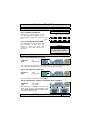
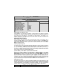
"+'$
Once you have installed the mainboard you still need to setup the BIOS before
you can run your PC. The EEPROM on the mainboard stores the AWARD BIOS
CMOS Setup Utility, which allows you to configure your system. When you
want to configure or make any changes to the configuration of your system
BIOS you must run the BIOS CMOS Setup Utility.
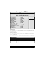
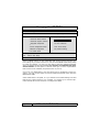
GETTING STARTED
Every time you start your computer, the system provides you with an opportunity to run the BIOS CMOS Setup Utility. As soon as you turn on your system,
press the <Delete> button to activate the BIOS CMOS Setup Utility.
If your computer finishes the POST (Power-On-Self-Test) the BIOS CMOS
Setup Utility will not be activated. If your computer completes the POST you
need to restart the system to activate the BIOS CMOS Setup Utility. To restart
the system, you can either turn the power off, press the reset button on your
chassis or press the <Ctrl> + <Alt> + <Delete> button. In all three cases the
system will restart and, to activate the BIOS CMOS Setup Utility, you must immediately press the <Delete> button.
2)
%")%*"8 2#2%*@"!
)**9
-"*?3
/$&.!
!#2-%
!-A%)56
#
!&)8 2-%
2*B!%
!&)#"*-%
%*
$
! $*"
$
!$
%*
C:%*
!$4$5$# #
!%
:1"
%
!$#"%
)9D%-9%8 2 ←↑↓→9) ->9:%*
/@@./*
#$ "
#$!
%&!
Page 22
845S-AV MAINBOARD
Ver 3.x
Managing the PC BIOS
Navigation Keys
You will notice a legend bar at the bottom of the main menu. The keys in this
legend bar show you how to navigate through the setup menus. The table below
lists the control keys with their corresponding functions:
!" #
$
!"
#$%&'
%(
%
+
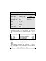
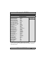
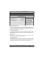
Date (mm : dd : yy)
Sets your system to the date that you specifiy (usually the current date). The
format is month, day, and year. Press the right or left arrow key to move to
the desired field (month, date, year). Press the PgUp or PgDn key to increment
the setting, or type the desired value into the field.
Time (hh : mm : ss)
Sets your system to the time you specify (usually the current time). The format is hour, minute, second. The time format is based on the 24-hour military-time clock. For example, 1 p.m. is 13:00:00. Press the right or left arrow
key to move to the desired field. Press the PgUp or PgDn key to increment the
setting, or type the desired value into the field.
IDE Primary / Secondary Master / Slave
This mainboard supports four IDE Hard Drives. These fields allow you to set
your Hard Drive parameters. Move the selection bar to the IDE Hard Drive you
want to configure. Press the "ENTER" key. If you select “AUTO” the system
BIOS will detect the HDD type automatically.
845S-AV MAINBOARD
Ver 3.x
Page 23
Managing the PC BIOS
-"*?3
/$&.!
&
(99+
/(""99+
!
!
!
!
/%@2)
>@>>
99,
$
$
)
)
&
8
-
**
%**
6
2
ED&4/- <8&$=&F
E$
63<2&/&$ F
E4
F
E4
F
*
%!
#""@
"@
)%
E@,F
E4
F
EF
E'&56'&F
E&
F
8
:
/
>=
=
=
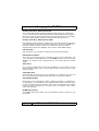
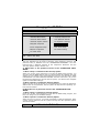
Drive A /B
The mainboard can support up to two floppy disk drives. These two selection
fields allow you to select the floppy drives that are installed on your computer.
Select the correct specifications for the diskette drive(s) installed on your computer.
0'0
=0'0
&
4
>=,,
,,
7>=,
,
;;,
4
.
,35)"$#3*
,35)"&/3*""3
35)"3
35)"
%3
35)"
%3
>=8
8
7>=8
8
;;8
Floppy 3 Mode Support
If you have installed a 3.5 inch high capacity floppy disk drive you need to enable this option. If you have not installed one of these drives use the default
setting.
Video
This field selects the type of primary video subsystem that is on your computer. The BIOS CMOS Setup Utility will automatically detect the correct video
type (See next page for detailed options).
Page 24
845S-AV MAINBOARD
Ver 3.x
Managing the PC BIOS
9
'&56'&
")'*")&*56
'*")&-
'&@6'&@'&@
6'&
$'&
*
#'&>
#
'*")&**
%*>)
%
#'&;>
#
'*")&**
%*;>)
%
242
)"
*)%""
%
)"
*
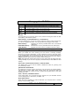
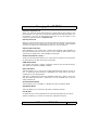
Halt On
This field allows you to decide which errors, detected during the Power On Self
Test (POST), will halt the system.
Base Memory / Extended Memory / Total Memory
This field displays the amount of memory detected by the system during boot
up. This is a display only field. You cannot make any changes to this field.
Base Memory:
Extended Memory:
Total Memory:
Indicates the memory installed below the conventional
1MB space.
Indicates the memory installed above the 1MB space.
Indicates the total memory installed in the PC system.
#!
Virus Warning
When you enable the virus warning you will receive a warning message
whenever a program (specifically, a virus) attempts to write to the boot sector
or the partition table of the hard disk drive. If you receive such a message you
should immediately run an anti-virus program. Keep in mind that this feature
only protects the boot sector and not the entire hard drive.
'( % %! %% &
"%!%# %!)!! &
"%
CPU L1 & L2 Cache Internal Cache / External Cache
This BIOS setting can be used to enable or disable the CPU’s L1 (primary) and
L2 (secondary) cache.
Quick Power On Self Test
If enabled the amount of time required to run the power-on self-test (POST)
will decrease. A quick POST skips certain steps. We recommend that you
disable quick POST. It is better to find a problem during POST than to lose data
during your work.
First / Second / Third Boot Device
These fields allow you to decide the boot sequence of your bootable devices
such as Floppy Drive, Hard Drive, CD ROM...etc
Boot Other Device
When this field is enabled you will be able Boot your computer from a another
device, not your HDD or FDD.
845S-AV MAINBOARD
Ver 3.x
Page 25
Managing the PC BIOS
-"*?3
/$&.!
3/$
6%1
#$C#)"
D%).$
2!/
-8
)
)
8
)
/"8
)
8
2")
*-
**
8
*-
**.
8
*4%
).%
'&>2*
/*)<
</*)<(#"5)+
</*)()+
)%2*
2)-
<&G8
&</#*
<*
4
--
1 4,
EF
EF
EF
E-
**F
E3>F
E#<2F
EF
EF
E
E2F
E-F
EF
,>
E%*F
E4
32F
EF
E4
F
*
%!
&
%
)"
"6 <
!%!
.
)
*
)
!"
!%)
*
"
@8 2"
)*
Swap Floppy Drive
This field is effective only in systems with two floppy drives. When Enabled is
selected physical drive B is assigned to logical drive A, and physical drive A is
assigned to logical drive B.
Boot Up Floppy Seek
When enabled, the BIOS tests (seeks) floppy drives to determine whether they
have 40 or 80 tracks. Only 360-KB floppy drives have 40 tracks; drives with
720 KB, 1.2 MB, and 1.44 MB capacity all have 80 tracks. Very few modern
PCs have 40-track floppy drives so we therefore recommend that you set this
field to Disabled to save time.
Boot Up NumLock Status
This controls the state of the NumLock key when the system boots. This field is
toggled between On or Off. When it is on the numeric keypad generates numbers instead of controlling the cursor operations.
Gate A20 Option
Gate A20 is a signal that gives the system access to addresses higher than
A19. If you select Fast the chipset will control this signal. If you select normal
a pin in the keyboard controller will control the signal.
Typematic Rate Setting
The keyboard controller determines the rate at which the keystrokes from the
keyboard are repeated. If you enable this option then the typematic rate and
the typematic delay can be selected.
Typematic Rate
This is the rate a character will repeat itself on the screen when you hold down
a key.
Page 26
845S-AV MAINBOARD
Ver 3.x
Managing the PC BIOS
Typematic Delay
This is the delay time (Msec) before the repetition of characters starts.
Security Option
This field allows you to select the “Setup” or “System” security option. It works
concurrently with the “ Set Supervisor Password” in the main menu.
When the "Setup" option is selected, you will be prompted to enter your
"Password" before you can start the BIOS CMOS Setup Utility. When you select
"System" option, you will be prompted to enter your password in order to load
the Operating System.
*%"
++,-
# %".!/.0/
"
%-$+
!
(++!0
12%1
OS Select For DRAM > 64MB
Only select OS2 if you are running an OS/2 operating system with a RAM
greater than 64 Mb. Otherwise, for all other operating systems, use the default
setting “Non-OS2”.
HDD S.M.A.R.T Capability
You may “enable” this option if your Hard Drive supports the S.M.A.R.T. technology (Self Monitoring Analysis Reporting Technology) feature. S.M.A.R.T. will
monitor and report your Hard Drive health status. Ask your Hard Drive Vendor
for further information.
Note: Using this feature may decrease system performance.
Report No FDD For WIN95
If you are not using a floppy disk this option allows you to release IRQ6. To do
this set this option to Yes. You should then also disable the onboard FDC
Controller in the Integrated Peripherals Screen.
)!+(
DRAM Timing Selectable
This field determines the DRAM read/write timing. The performance parameters of the memory chips (DRAM) you have installed will determine the value
in this field. Do not change the value from the factory setting unless you install
new memory that has a different performance rating than the original DRAMs.
CAS Latency Time
The time delay (in clock cycles, CLKS) that passes before the SDRAM starts to
carry out a read command after it has been received. The number of CLKs that
occur before the first part of a burst transfer is completed is also determined
by this field.
DRAM RAS# to CAS# Delay
When the DRAM is refreshed, both rows and columns are addressed separately. This setup allows you to determine the timing of the transition from
Row Address Strobe (RAS) to Column Address Strobe (CAS).
845S-AV MAINBOARD
Ver 3.x
Page 27
Managing the PC BIOS
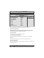
-"*?3
/$&.!
3&"
<&/)
#&)/
&)
$)"
<&<&H
#&H
<&<&H$)"
<& -A%)-
<&</"
8 2#)"
6
8 2#)"
6
<&#)"
&'$&*%B(8+
$
/"
E8$F
EF
EF
EF
EF
E4
3##F
E&%
F
EF
EF
EF
EF
EF
EF
*
%!
DRAM RAS# Precharge Time
If the DRAM is not continually refreshed it’s data will be lost. DRAM is normally
refreshed as a result of a single request. This field lets you select the number of
CLKs allocate for the RAS to accumulate its charge before the DRAM is refreshed. If there is not sufficient time then the refresh may be incomplete and
some of the data can be lost.
DRAM Data Integrity Mode
Error Checking and Correction (ECC) should only be used in conjunction with a
special 72-bit ECC RAM. If you are using ECC RAM you should select ECC. This
feature will enable the system to detect and correct single-bit errors and detect
(not correct) double-bit errors. If you do not have ECC RAM then select NonECC (the default mode).
Memory Frequency For
This field allows you to manually select the frequency of the memory modules
you are using. This mainboard supports both PC100 and PC133 SDR modules. If
you run the FSB at 533MHz the only default option for this filed is PC133, or if
the FSB is at 400MHz the option for this filed can be AUTO, PC-133 or PC-100.
If you do not know what the frequency of your memory modules is then select
auto and the system will automatically decide.
System BIOS\ Video BIOS \Video RAM Cacheable
These fields enable (disable) the caching of the System BIOS , the Video
BIOS and the Video RAM. The Sysem BIOS is cached at F0000h-FFFFFh, the
Video BIOS is cached at C0000h-C7FFFh, and the Video RAM is cached at
A0000h-AFFFFh. All three are cached via the L2 cache. If these options are enabled, access to the system BIOS may speed up BUT if any other program tries
to write to the memory locations specified above then the system will crash. We
recommend that you disable these options. Note The System/Video BIOS can
only be cached when the System BIOS/Video BIOS has been shadowed.
AGP Aperture Size
This field selects the size of the Accelerated Graphics Port (AGP) aperture. The
aperture is a portion of the PCI memory address range dedicated for graphics
memory address space. Host cycles that hit the aperture range are forwarded
to the AGP without any translation. The default is 64MB. You may increase this
memory when you need to have faster access for 3D graphics applications.
Page 28
845S-AV MAINBOARD
Ver 3.x
Managing the PC BIOS
2*1('
-"*?3
/$&.!
$%
-
"
!
23#"*$$# $$ 2
$$ 2
$&
$&
23#"*)
$# )
$ 2
)
$ 2
)
&
)
&
8#
8=
%**
&%
*-
8
).
$21<24-%)
=8$
24$
=$
24
2
-##
2
$
2
$
&</
)
<:@/:&)
<&/
<%*:
<$
2
$$
$$
$$
)
#$
&
$1<24&!$1<-
'$
&
$
&
$
<D
EF
E&%
F
E&%
F
E&%
F
E&%
F
EF
E&%
F
E&%
F
E&%
F
E&%
F
EF
EF
E&%
F
E&'$F
EF
E8//2424IF
E4/<F
E#3-F
EF
E-;5 <DF
E-;5 <DF
E4
F
E@
F
EF
E!F
<:@/:
E7;5 <D7F
E$$F
E$$7F
EF
E2!!F
E>F
E>F
E>F
*
%!
On-Chip Primary PCI IDE/On-Chip Secondary PCI IDE
These two options (option 1 and option 6) allows you to enable or disable the
onboard IDE Interface.
845S-AV MAINBOARD
Ver 3.x
Page 29
Managing the PC BIOS
Primary/Secondary, Master/Slave PIO
The four IDE PIO (Programmed Input/Output) fields let you set a PIO mode
(0-4) for each of the four IDE devices that the onboard IDE interface supports.
Modes 0 through 4 provide successively increased performance. In Auto mode,
the system automatically determines the best mode for each device.
Primary/Secondary, Master/Slave UDMA
Ultra DMA/66 implementation is possible only if your IDE hard drive supports it
and the operating environment includes a DMA driver (Windows 98 OSR2 or a
third-party IDE bus master driver). If your hard drive and your system
software both support Ultra DMA/66, select Auto to enable BIOS support.
USB Controller
This field allows you to enable or disable the onboard USB Controller.
USB Keyboard Support
If you are using an older (legacy) operating system (such as MS-DOS) and
you’re installing a USB keyboard you must enable this Field. For PnP O/S like
Windows 98, Windows 2000, Windows ME etc you should retain the default
setting.
AC97 Audio
If you want to enable the on-chip audio capabilities of your system you need
use the default setting “Auto”. If you install an add on sound card you must
disable this field.
Init Display First
When both AGP and PCI VGA card are installed on a mainboard, this field can
be used to determine the display loading priority during System Startup.
IDE HDD Block Mode
Block Mode is also called Block Transfer, Multiple Commands, or Multiple Sector Read/Write. If your IDE hard drive supports Block Mode (most new drives
do) then this field should be enabled. If this field is enabled then the optimal
number of block read/writes per sector the drive can support will be determined automatically.
POWER ON Function
The POWER ON Function allows you to select different ways to power on your
PC System.
Page 30
845S-AV MAINBOARD
Ver 3.x
Managing the PC BIOS
KB Power ON Password
When you select KB Power ON Password to power ON the PC system in the
previous field, you may enter your personal password into this field. When you
are finished , you may use the password to power on your PC system. If you
forget your password refer to section 2.8.3.
Hot Key Power On
When you select Hot Key Power On to Power ON the PC System in the previous
selection field, you may select a set of “Hot Key” in this field . When finished
you may use the hot key combination to power on your PC System.
Onboard FDC Controller
Select Enabled if your system has a floppy disk controller (FDC) installed on
the system board and you want to use it. If you install an add-in FDC or the
system has no floppy drive, select Disabled in this field.
Onboard Serial Port 1/Port 2
These two selection fields allow you to select the I/O address and corresponding interrupts for the first and second serial ports.
UART Mode Select
Your system may offer a variety of infrared modes on the second serial port.
The options are Standard, HPSIR or ASKIR.
RxD, TxD Active
This field allows you to set the IR reception/transmission polarity as high or
low. To determine which polarity is appropriate you must refer to the documentation for your IR peripheral.
This field is usually found under the Onboard Serial Port 2 option. If you disable the Onboard Serial Port 2 option then you will probably not be able to
configure this field.
IR Transmission Delay
This field allows you to “Enable” or “Disable” the IR Transmission Delay.
UR2 Duplex Mode
This Field allows you to select the IR half or full duplex function.
Use IR Pins
To determine the correct settings for the TxD and RxD signals of your IR peripheral component, you need to consult the components manual.
845S-AV MAINBOARD
Ver 3.x
Page 31
Managing the PC BIOS
Onboard Parallel Port
This item allows you to determine the I/O address and the IRQ for the onboard
parallel port. The default settings are adequate and should not give you any
problems. If they do you can try to change them.
Parallel Port Mode
This field allows you to select an operating mode for the onboard parallel
(printer) port. Select Normal, Compatible, or SPP unless you are certain your
hardware and software both support one of the other available modes.
EPP Mode Select
This field allows you to choose the EPP version you want to use. We recommend that you use EPP 1.9 for the best performance but if you do you may
have some connection problems so try setting it to EPP 1.7.
ECP Mode Use DMA
This item allows you to select a DMA channel for the parallel port for use during ECP.
PWRON After PWR Fail
See the following table for all the options.
A
1""*
%!&#*
!%"J*
!!
I
%%*"$
%
*
3
"
A
1""*
%!&#*
!%@"%
3
)*
3
?
A
1"*
%!&#*
!%@"%
"
" % ! !! !
" *
!% ))% ! " J
*
!!""&#*
!%
))%@
!!""
*
% ! " J *
" " &# *
!% )3
)%@"*
3
""*
%
Game Port Address
This field allows you to select the I/O address for the onboard game port. Default is 201.
Midi Port Address
This field allows you to select the I/O address for the onboard MIDI port. Default is 330.
Midi Port IRQ
This field allows you to select the IRQ for the onboard MIDI port. Default is 10.
Page 32
845S-AV MAINBOARD
Ver 3.x
Managing the PC BIOS
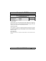
31"*%
-"*?3
/$&.!
-
%
&#$ -%)
&#$ %*/*
$
6
2!!"
6
2!! %*
%*/*
%*
$
!32!!$1<38//4
#$/<3/"
1.2&4
<%&
:(
!
"+&
:/(""99+&
KK<
'
/KK
$ >
$ )
>
)
-@#2@$/$
EF
E($2+F
E!F
E8.)F
EIF
E
*'F
EF
EF
E 32!!F
E,>>LF
EF
EF
>
>9>9>
EF
EF
EF
EF
EF
*
%!
ACPI function
This item allows you to enable/disable the Advanced Configuration and Power
Management (ACPI).
ACPI Suspend Type
This mainboard supports one suspended state: S1(POS): Power On Suspend.
Power Management
This category allows you to select the degree of power saving. The choices are
shown in the menu on below.
Power Management
%*
%*
M"
:
:%*
%*
M
!
&
%
)"
%1"
@)"
!"!
":)*!
$
")"!
,
Video Off Method
This field determines how a monitor is made blank. See the table on next
page.
845S-AV MAINBOARD
Ver 3.x
Page 33
Managing the PC BIOS
65I4#N8.
8.)
$%**
/")
)%"
%
!!")"
3
B
)"
B
*
.
"
%!!
/"
*
.
"
%!!
) " *
! % %**
" * $
3
($+ ! " 6
)
) 3
)
*
%
Video Off In Suspend
This field has two options: Yes or No. These options allows you to determine
the way in which the monitor is switched off.
Suspend Type
This field allows you to select the status of the CPU when the system goes into
the suspend mode. If you select by Stop Grant the CPU stops running completely, by "PWRON Suspend" keeps the CPU.
Suspend Mode
When enabled, after the set time of system inactivity, all devices except the
CPU will be shut off.
HDD Power Down
If this field is enabled, after a set time of system inactivity, the hard disk will
be powered down while all the other devices remain active.
Soft-Off by PWRBTN
Pressing the power button for more than 4 seconds forces the system to enter
the Soft-Off state when the system has “hung”.
CPU THRM-Throttling
This field allows you to select the CPU Throttle rate. When the CPU temperature is too high, the onboard hardware monitoring will tell the CPU to reduce
it’s processing speed to the throttling speed to protect the CPU . This function
will not work when the CPU Warning Temperature is Disabled.
Wake On LAN
An input signal from the LAN will wake up the system from a soft off state.
Resume By Alarm
This field allows you to wake up the system at a predetermined date in the
future. If you select Enabled then you need to enter the date and the time at
which you want the system to “wake up.”
**Reload Global Timer Events**
When Enabled, an event occurring on each device listed below will restart the
global time for the standby mode.
Primary IDE 0
Primary IDE 1
Secondary IDE 0
Secondary IDE 1
FDD, COM, LPT Port
PCI PIRQ[A-D]
Page 34
845S-AV MAINBOARD
Ver 3.x
Managing the PC BIOS
41161++*
-"*?3
/$&.!
-6-7-&$&%
<#
!%
EF
<
%)#
8 E&%
(#+F
× <D<
%) E$F
$# 56'&$
* EF
*
%!"
!%)
<:
#
!%
(#+"
%:%*!
%"3
""
)%%)"
%)
!)
""2)
Reset Configuration Data
Normally, you leave this field Disabled. If you have installed a new add-on and
the system reconfiguration has caused such a serious conflict that the operating system cannot boot then select Enabled. Selecting Enabled will reset the
Extended System Configuration Data (ESCD).
Resources controlled By
Award Plug and Play BIOS has the capacity to automatically configure all of the
boot and Plug and Play compatible devices. However, this capability means
absolutely nothing unless you are using a Plug and Play operating system such
as Windows 98.
IRQ Resources
When resources are controlled manually, assign each system interrupt a type,
depending on the type of device using the interrupt
PCI/VGA Palette Snoop
Some display cards are non-standard VGA card (such as graphics accelerator
or MPEG Card) which may not display color properly on your screen. “Enable”
the setting in this field may correct this problem. Leave it “Disabled” as the
default setting shown above if you are using the normal display card.
845S-AV MAINBOARD
Ver 3.x
Page 35
Managing the PC BIOS
51+&'(
-"*?3
/$&.!
-& !"
#$1/*%
#%#$/*%
#%-&4*
#%-&4*
#%-&4*
6))#
(6+
,(6+
(6+
N,6
N6
36
68&/(6+
,68(6+
"%
/*%
EF
#57-
;<$
><$
><$
76
,6
>6
7,6
>6
36
6
,6
EF
*
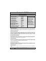
%!"
The PC Health Status menu allows you to monitor the health status of your PC
system. You can select a field of interest and monitor it’s status.
CPU Warning Temperature
This field allows you to select an operating temperature range for your CPU. If
the CPU temperature moves out of this range, any warning mechanism you
have programmed into your system will be activated.
Current CPU Temp.
This field shows the current temperature for CPU.
Current FAN1/FAN2/FAN3 Speed
This field shows you the speeds of the three cooling fans on the mainboard.
Vcc Core
This field and the fields below it show you the current system voltage
Shutdown Temperature
When the system reaches a certain maximum temperature the system will
automatically shutdown.
Page 36
845S-AV MAINBOARD
Ver 3.x
Managing the PC BIOS
78$69'*+'
-"*?3
/$&.!
879!%&
!
*
#$#
).<
E>:F
&%
)$# #. EF
**)% EF
#$
565$# #
). E!%F
%!"
CPU Clock Ratio
This field allows you to select the CPU clock ratio. Most CPU clock ratios are
fixed inside the CPU by the manufacturers that prohibit you to make any
changes. In this case, the setting in this field will make no change to the CPU
clock ratio since it locks and is automatically determined.
Auto Detect PCI Clk
When “Enabled” is selected, the mainboard will detect the presence of devices
on PCI slots. When there is no device present on some of the PCI connectors,
the clock on the related PCI slot will be disabled to reduce the Electro-Magnetic
Interference (EMI).
Spread Spectrum
When Spread Spectrum is enabled, the EMI radiation on this mainboard will be
reduced.
845S-AV MAINBOARD
Ver 3.x
Page 37
Managing the PC BIOS
%:'
-"*?3
/$&.!
!#2-%
!-A%)56
#
!&)8 2-%
2*B!%
!&)#"*-%
%*
$
! $*"
$
!$
%*
C:%*
!$4$5$# #
!%
:1"
%
!$#"%
#9D%←↑↓→9) ->9C:%*
2*:)*#2/$
There is CMOS memory on the mainboard that can be used to store the system settings. If you don't know how to use the Award BIOS CMOS Setup Utility
to select the settings, you may use this field to load the optimized defaults
which are defined in the system BIOS. Our engineer recommends the Optimized Defaults. If this option is selected it will give a series of parameters
that will ensure the reliability and performance of your PC.
If you lose your CMOS data or you don’t know how to complete the setup procedure, you may use this option to load the Optimized default values from the
BIOS default table.
If the CMOS data is corrupted, or if you selected some CMOS settings and find
that the PC system becomes very unstable, you should try to load the optimized default values first and then re-configure the BIOS.
Page 38
845S-AV MAINBOARD
Ver 3.x
Managing the PC BIOS
!1"
-"*?3
/$&.!
!#2-%
!-A%)56
#
!&)8 2-%
2*B!%
!&)#"*-%
%*
$
! $*"
$
!$
%*
C:%*
!$4$5$# #
!%
:1"
%
!$#"%
#9D%←↑↓→9) ->9C:%*
#"55$
The “SUPERVISOR PASSWORD” is for you to control unauthorized access to
your BIOS CMOS Setup or Booting into the your PC system. The Supervisor
Password option is used together with the Security Option in section 3.4.
When "Setup" is selected in the Security Option:
If you want to change any BIOS setting, you will have to key-in the Supervisor
Password so that you can start the BIOS CMOS Setup Utility and change the
system setting.
When "System" is selected in Security Option:
Whenever you turn on the PC, it will request the user to enter the Password in
order to boot up your system. Without the correct password, the PC system
will stop and the operating system will not be loaded.
845S-AV MAINBOARD
Ver 3.x
Page 39
Managing the PC BIOS
1"
-"*?3
/$&.!
!#2-%
!-A%)56
#
!&)8 2-%
2*B!%
!&)#"*-%
%*
$
! $*"
$
!$
%*
C:%*
!$4$5$# #
!%
:1"
%
!$#"%
#9D%←↑↓→9) ->9C:%*
#"55$
The User Password can be used to check the user's authority. However, this
password entry is different from the "SUPERVISOR PASSWORD". The User
Password has a different function to the "Supervisor Password" and the
"Security Option" setup in Section 3.4.:
A. When there is the password stored in the "SUPERVISOR PASSWORD"
1. When "Setup" is selected in the Security Option:
When you use the "User Password" to log into the BIOS setup program, you
can only view the BIOS settings, but you cannot change any settings. The only
setting you can change is the "User Password" and you can also select "SAVE
& EXIT SETUP" and "EXIT WITHOUT SAVING" from the main menu. (If you use
the Supervisor Password to log into the PC system, you will have the complete
rights to all the BIOS settings.
2. When "System" is selected in Security Option:
When you turn on the PC system, it will request that you enter the Password.
Without the correct password, the PC system will stop and the operating system won't be loaded.
B. When there is no password stored in the "SUPERVISOR PASSWORD"
1. When "Setup" is selected in Security Option:
Users can use the "User Password" to log into the BIOS setup program, and
they can change any of the BIOS settings.
2. When "System" is selected in Security Option:
When you turn on your PC, you will be requested to enter the Password. Without the correct password, the PC system will stop and the operation system
will not be loaded.
Page 40
845S-AV MAINBOARD
Ver 3.x
Managing the PC BIOS
#!;-.6-.<(!*
-"*?3
/$&.!
!#2-%
!-A%)56
#
!&)8 2-%
2*B!%
!&)#"*-%
%*
$
! $*"
$
!$
%*
C:%*
!$4$5$# #
!%
:1"
%
!$#"%
#9D%←↑↓→9) ->9C:%*
#2C:/$5&
C:/$
Save & Exit Setup
This option will save all the setup values to CMOS RAM and exit the SETUP
utility. Move the selection bar to “SAVE & EXIT SETUP” and press the “Enter”
key, then type “Y” and press the “Enter” key again. The values you have entered will be saved and all the information stored in the CMOS memory.
Exit Without Saving
This option will exits the setup utility without saving any of the values you
changed in the CMOS RAM. If you do not want to save any of the changes, or
settings you selected in the BIOS SETUP utility, move the selection bar to the
“EXIT WITHOUT SAVING” option. Press the “Enter” key. Then press “Y”
845S-AV MAINBOARD
Ver 3.x
Page 41