1
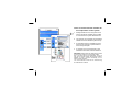
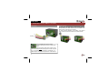
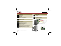
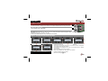
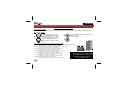
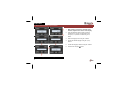
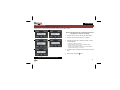
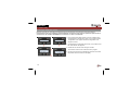
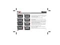
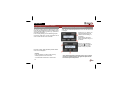
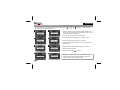
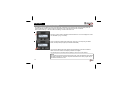
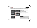
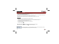
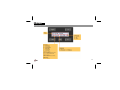
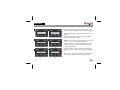
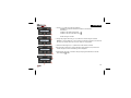
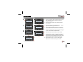
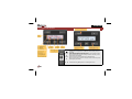
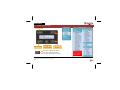
MULTIROOM TEMPERATURE CONTROLLER SYSTEM Up to 32 sensors per controller Up to 7 zones Up to 31 program instructions can be saved per sensor or zone Program types : day programs working day programs weekend programs week programs Power supply: 12VDC ... 18VDC/50mA VMB1TC VMB1TCW VMB1TSW VMB1TS There are several manuals available for this temperature control system: 1. Getting started manual, This guide can be found in the sensor package, and provides an overview of the system. Read this first! 2. This manual, use it together with the getting started manual for standard system set-up. 3. An extended manual is available for download. Use this manual for special features and to study examples. 4. A controller menu overview sheet is also available for download, used as reference. IMPORTANT: VMB1TS(W) and VMB1TC(W) modules have the unique feature of user firmware update! Due to the large amount of applications, check our web site for manual updates and firmware updates. Updates can add or improve functionality, not described in these manuals. Your current firmware version can be checked using the Velbuslink PC software. In this manual: 1. How to connect the temperature controller p.4 2. How to connect the temperature sensor p.5 3. Setting the address for sensor and controller p.6 4. Assign a relay channel to a temperature sensor function p.7 5. Set the menu language on the controller p.8 6. Setting the clock for the controller p.9 7. How to set up the sensor with the controller p.10 8. Operating the temperature controller p.12 9. Programming the temperature controller p.16 10. Screen & LED indicators p.21 11. Controller menu overview p.22 ENGLISH 1. Temperature controller 'VMB1TC' connection Connection Battery backup To avoid losing the clock when a power failure occurs, a backup battery (3V Lithium CR2032) can be installed in the battery holder at the back of the module. To avoid premature depletion of the battery, only install it when permanent power is supplied to the Velbus system. 9 9 Place the TERM jumper if the module is connected at the start or end of a cable on the Velbus. Remove the jumper in all other cases. Place a jumper on the end module of the longest cable only, NOT on each end point. E.g. a normal two-story house will have 3 terminators: 1 upstairs end point, 1 downstairs end point and 1 in the fuse box. 4 ENGLISH 2. Temperature sensor 'VMB1TS' connection and button+indicators overview LED indication 1 2 3 4 5 Cooling mode Comfort mode Day mode Night mode Heating or air-conditioning on 6 Temperature sensor Settings 8 9 Address setting* Terminator 14 15 Wiring power supply 12 to 18Vdc Velbus Sensor 14 9 Controls 7 7+11 7+12 7+13 10 11 12 13 15 Mode pushbutton Assign high temperature alarm* Assign low temperature alarm* Assign circulation pump* Assign airco (COOL)* 8 BUS TWISTED PAIR (0.5mm²) Assign day setup for Central heating (DAY)* Assign extra fan for boost heat (BOOST)* Assign heater (HEAT)* 1 2 3 4 10 11 12 13 5 6 * only available for the VMB1TS module 7 5 ENGLISH 3. Address selection In order to identify each module in your system it is necessary to set an unique address for each module. This address will also be used by the PC software to scan all the addresses and to identify the modules. 0 VMB1TSW / VMB1TCW 1 Adress setting trough Velbuslink© VMB1TS : ADDRESS SETTING USING THE 2 ADDR ROTARY SWITCHES. CAUTION: Addresses 81,91,A1, B1, C1, D1, E1, F1 & FF can NOT be used. Examples of valid addresses: 01, 02, 03…. 0A, 0B…, 1A, 1B… A total of 248 valid addresses can be selected for this module. Example of a valid address: “0 1” VMB1TC : ADDRESS SETTING USING THE MENU 5 ↑ ↑ ↑ ↑ ↑ ↑ ↑ ↑ ↑ ↑ ↑ ↑ 6 ↑ ↑ ↑ Each module on the Velbus system must have its own unique address, write down the address for later use! ↑ ↑ ↑ 4 ↑ ↑ 7 3 ↑ ↑ ↑ ↑ ↑ 6 2 ↑ ↑ ↑ 1 1. Press and HOLD the ‘Menu’ button to open the extended menu. 2. Scroll through the extended menu using ↑ or ↓ buttons until the ‘’Configuration” menu appears, select using the → button. 3. Scroll through the Configuration menu using ↑ or ↓ buttons until the ‘’Address” menu appears 4. Select the Address menu using the → button. 5. Enter a unique address (‘01’...‘FE’) using the ↑ or ↓ button. 6. Confirm the address using the → button. 7. Exit the menu using the button. ENGLISH 4. Assign a relay channel to a temperature sensor function (can also be performed using PC, advised) Only available for VMB1TS On the sensor module: Set the sensor module in anti-freeze mode by pressing the push button on the front panel repeatedly until all LED’s are off. Mode First remember the address of the module to reinstate it later on. Set the Address rotary switches to 'C1', 'C2', 'C3, or 'C4', depending on the chosen channel. The 'MODE' LED of that channel will flash to indicate learning mode. Set the MODE and TIME1 rotary switches of the chosen channel to '0' (instant control) Time1 ADDR On the relay module: Select one of the below functions: (ask someone to help if needed) To assign a room heater or room water valve to a relay contact (>> this will mostly be used) Press button 13 on the sensor until relay engages 10 11 12 13 To assign the air-conditioning system (fan or compressor control) to a relay contact: Press button 10 on the sensor until relay engages. To assign the central heating system day/night setting to a relay contact: 7 Press button 11on the sensor until relay engages. To assign an extra fan for quick heating or cooling (boost) to a relay contact: Press button 12 on the sensor until relay engages To assign the central heating system main pump to a relay contact Do not forget to set the address of the Press button 7+ button 13 on the sensor until relay engages relay module back to its original value. To assign a low temperature alarm to a relay contact Press button 7+ button 12 on the sensor until relay engages Repeat the procedure for other senTo assign a high temperature alarm to a relay contact sors or other functions. Press button 7+ button 11 on the sensor until relay engages 7 ENGLISH 5. Set the menu language on the controller 4 ↑ ↑ ↑ ↑ ↑ ↑ ↑ ↑ 6 ↑ ↑ ↑ ↑ See display & menu overview on page 21 & 22 8 1. When applying power to the controller for the first time, only the time is shown on the display. 2. Press and HOLD the ‘Menu’ button to open the extended menu. Scroll to “Configuration” menu using the ↑ or ↓ buttons. Confirm using the → button. 3. Enter the language menu using the → button. 4. Choose the desired language using the ↑ or ↓ buttons. 5. Confirm the language selection using the → button. 6. Exit the menu using the button. ↑ ↑ ↑ 3 5 ↑ ↑ ↑ ↑ 2 ↑ ↑ ↑ ↑ ↑ 1 ENGLISH 6. Setting the clock It is important to set the correct time for the internal clock. Setting the time on this module will synchronise all clocks in your Velbus system. ↑ ↑ ↑ ↑ ↑ ↑ 3 5 ↑ ↑ ↑ ↑ ↑ ↑ ↑ 2 4 ↑ ↑ ↑ ↑ When applying power to the controller for the first time, only the time is shown on the display. 1. Open the “short” menu by pressing the ‘Menu’ button. 2. Scroll to "clock set" menu using ↑ or ↓ buttons. 3. Select the set clock menu using the → button. The dayindication flashes. Set the day using ↑ or ↓ buttons. Confirm using the → button. The hour-indication flashes. Set the hour using ↑ or ↓ buttons. Confirm using the → button. The minutes-indication flashes Set the minutes using ↑ or ↓ buttons. ↑ ↑ ↑ 1 4. Confirm using the → button to start the clock from the set time. 5. Exit the menu using the button. See display & menu overview on page 21 & 22 9 ENGLISH 7. Sensors setup Searching for temperature sensors Before the controller can work with the temperature sensors it must first scan the network for all connected sensors. If temperature sensors are installed or removed afterwards, the search process must be repeated to update the list of sensors to the new situation. NOTE: Make sure "all rooms" or "zone" is not selected. 3 ↑ ↑ ↑ ↑ ↑ ↑ ↑ 1. Press and HOLD the ‘Menu’ button to open the extended menu. Scroll through the extended menu using ↑ or ↓ buttons until the ‘Configuration’ menu appears. Select the configuration menu using the → button. ↑ 1 2. Scroll through the Configuration menu using ↑ or ↓ buttons until the ‘Scan sensors’ item appears. 4 ↑ ↑ ↑ ↑ 10 ↑ ↑ ↑ ↑ 2 3. Confirm the scan sensors menu using the → button. The search for sensors on the network is now in progress. 4. Once the search process is completed, the first of the connected temperature sensors is shown on the display. ENGLISH Assign sensor names (can also be done using PC, advised) Each sensor can have a specific label or name (Default all the temperature sensors will have the same name ‘Temp sensor’ & address) 5 ↑↑ ↑ ↑ ↑ ↑ ↑ ↑ 7 ↑ ↑ ↑ ↑ ↑ ↑ ↑ ↑ ↑ ↑ ↑ ↑ ↑ ↑ ↑ ↑ ↑ 3 2. Scroll through the extended menu using ↑ or ↓ buttons until the ‘Sensor settings’ menu appears. 3. Select the Sensor settings menu using the → button. 6 2 1. Press and HOLD the ‘Menu’ button until the extended menu appears. 4. Scroll through the menu using the ↑ or ↓ button until the ‘Change name’ item appears. ↑ 5. Select the change name menu using the → button. The cursor flashes on the first character of the name. The second line indicates the address of the selected temperature sensor. With this address the location of the sensor can be determined. ↑ ↑ ↑ ↑ ↑↑ 1 6. Change the character at the cursor location using ↑ or ↓ buttons and confirm using the → button. The cursor moves to the next character. 7. Repeat step 6 until all characters are entered. ↑ 8. Exit the menu using the button. Press the ‘Location’ button to select the next sensor. ↑ 9. Repeat steps 1 through 8 until every sensor has a meaningful name. ↑ ↑↑ ↑ ↑ ↑ ↑ ↑↑ 8 ↑ 4 11 ENGLISH 8. operating the temperature controller Select room or zone To set up a heating system for different rooms, each room will need a temperature sensor. Multiple rooms can be grouped together in zones* (e.g. ground floor, second floor, bedrooms…). Prior to setting heating (or air-conditioning) requirements for a certain room or zone, the desired room or zone must be selected on the controller. Recall and change the desired temperature At any time the desired temperature for a room can be shown and/ or changed. Press the ↑ or ↓ button. The desired temperature for the selected room is flashing on the display. When desired, change the target temperature using ↑ or ↓ buttons. Return to normal display by pressing the or ← button or simply wait for ±5 seconds without touching any button. Press the ‘Location’ button repeatedly until the desired room or zone is displayed. Remark: Press and hold the ‘Location’ button for easy switching between rooms and zones. * See extended manual how-to create zones 12 Upon switching between anti-freeze, night, day or comfort preset, the target temperature will again be replaced with the selected preset temperature. ENGLISH Setting the comfort, day and night temperature presets The temperature sensor VMB1TS can be used in 4 modes (comfort its own preset for the desired temperature. 5 1 , day , night or standby -). Every mode has 1. Press the ‘Location’ button repeatedly until the desired room or zone for which one wants to set the preferred comfort, day and/ or night temperature is displayed. 2. Press the ‘Menu’ button to enter the short menu. 6 2 3. Select the temperature settings menu using the → button. 4. Scroll to the desired mode using ↑ or ↓ buttons. 5. Select the desired mode using the → button, the temperature starts flashing. 7 3 6. Set the desired mode temperature using ↑ or ↓ buttons. 7. Confirm using the → button. 8. Exit the menu using the or ← button. 4 ↑ ↑ ↑ ↑ 8 NOTE: In the “Sensor setting” menu, it is possible to adjust the temperature limits, these limits will also be used for the "Upper cool temp." and Anti-freeze presets. 13 ENGLISH Start sleep timer or switch between preset modes The heating or (air-conditioning) can be forced temporary (sleep timer) into a certain mode. During this time period, all program instructions will be ignored. When the sleep timer ends, normal program execution is resumed. This could be useful e.g. to force the bathroom heating in comfort mode for an hour. 1 Press the ‘Location’ button repeatedly until the desired room or zone is displayed or select "ALL ROOMS" if you go on holiday. 2 Once you switch the desired mode (anti-freeze, night, day or comfort) using the ‘Mode’ button, the sleep timer (hourglass) is activated automatically. The LED of the Mode push button (bottom left) starts flashing as well as the indication LEDs on the sensor module. The display indicates an hourglass. The remaining time of the sleep timer is displayed, unless a zone was selected. NOTE: To cancel the sleep function and keep the preset mode, press and HOLD the mode button until sleep (hourglass) is cancelled. This preset will remain active until a program step is executed for this sensor or zone. 14 ENGLISH Setting the sleep time (temporary mode) Once the heating (or air-conditioning) is in temporary mode, the duration of the sleep timer can be increased or decreased. This could be useful e.g. to leave the heating in comfort mode a few hours/days or manual. 1 4 2 5 1. If sleep timer is active, press the ‘Menu’ button 2. The ‘Sleep timer’ menu appears on the display. Select the item using the → button. 3. The remaining sleep timer-time flashes on the display. Change the time using ↑ or ↓ button. 4. Confirm the changes using the → button. Remark: Cancel the changes by pressing the ← button. 5. Exit the menu using the or ← button. 3 YOU CAN SELECT : Hours Days (in case of holiday..) Manual (always locked, in case of summer time..) 15 ENGLISH 9. Programming the controller This controller has two ways to program heating or cooling periods 1- Normal week timer programming (see next pages) 2- Wake-up and goto-bed alarm timer feature This unique alarm feature makes programming heating or cooling periods very easy. It is even possible to link this timer to other modules in your Velbus system (eg. Open de blinds, power-up the radio...) The alarm can also be turned ON or OFF in a few steps, just like any clock radio or alarm clock How to do this: First set the time you go to sleep and the time you want to wake up. 1. 2. 3. 4. 5. 6. 7. Open the “short” menu by pressing the ‘Menu’ button and select the “Alarm clock set” menu using ↑ or ↓ buttons. Select the “Alarm clock set” menu using the → button. Select the “On” (or OFF to disable the alarm) setting Confirm using the → button. The hour-indication flashes. Set the “Wake-up time” (hour/minutes) using ↑ or ↓ and → buttons. Next Set the “Go-to-bed time” (hour/minutes) using ↑ or ↓ and → buttons. Confirm using the → button. Exit the menu using the button. Next activate the wake-up and Go-to-bed If the alarm function is active, the clock symbol timers in the program. (see next pages) is indicated on the display. In this program example, you see that from Monday to Friday, 30 minutes (offset) before wake up time, the temperature in the living room will be set to day preset. 16 ENGLISH Program step overview ↑ ↑ ↑ ↑ 17 ENGLISH Entering / changing a program instruction 4 ↑ ↑ ↑ ↑ ↑ ↑ ↑ ↑ 1 1. Press the ‘Location’ button repeatedly until the room or zone of which a program instruction needs to be added is displayed 2. Press and hold the ‘Menu’ button until the extended menu appears. 3. Select the program menu using the → button. The display shows the first program instruction. ↑ ↑ ↑ ↑ ↑ ↑ 6 ↑ ↑ 18 ↑ ↑ ↑ ↑ ↑ 3 5 ↑ ↑ ↑ 2 Remark: When no instructions are entered yet, the line will be empty “- - -”. Skip step 4 and proceed with step 5. 4. Scroll through the program instructions using the ↑ button until the instruction line is empty or until the instruction that needs to change is shown. 5. Press the → button to add an instruction or to select the instruction that needs to change. The first data entry field flashes. 6. Use the ↑ or ↓ button to set the day(s) on which the instruction needs to be executed. Confirm using the → button. ENGLISH 7 ↑ ↑ ↑ ↑ 7. Use the ↑ or ↓ button to set the time reference. Possibilities on which the instruction needs to be executed are: - Exact time , - Relative to the Wake-up alarm time - Relative to the Go-to-bed alarm time Confirm using the → button. 8 ↑ ↑ ↑ ↑ 8. Change the program time using ↑ or ↓ buttons and confirm using the → button. Remark: In case the Wake-up or Go-to-bed time is selected as reference, the offset can be set per 15 minutes with a limit of 4 hours. Step 9 is not applicable. 9. Set the minutes using the ↑ or ↓ button and confirm with the → button. 9 10 ↑ ↑ ↑ ↑ 10.Set the mode (comfort, day, night or anti-freeze mode) with the ↑ or ↓ button and confirm using the → button. The flashing cursor disappears. 11.Repeat steps 4 through 10 to add or change more program instructions or exit the menu using the button. ↑ ↑ ↑ ↑ 19 ENGLISH Deleting a program instruction 5 ↑ ↑ ↑ ↑ 2 ↑ ↑ ↑ ↑ 1 ↑ ↑ 3. Select the program menu using the → button. The display shows the first program instruction. 4. Scroll through the program using the ↑ or ↓ buttons until the instruction that needs to be removed is shown. ↑ ↑ ↑ 3 2. Press and hold the ‘Menu’ button until the extended menu appears. ↑ ↑ ↑ 6 1. Press the ‘Location’ button repeatedly until the room or zone of which the program instruction needs to be changed is displayed. 5. Select the instruction that needs to be deleted using the → button. The first data entry field flashes. ↑ 7 ↑ ↑ ↑ ↑ ↑ 4 ↑ ↑ ↑ 6. Use the ↑ button until the instruction line is empty. 7. Confirm using the → button. The program instruction is removed from the memory, the flashing cursor disappears and the next program instruction is shown. If this was the last instruction, the display remains empty. ↑ 20 ↑ ↑ 8. Repeat steps 4 through 7 to remove other program instructions or exit the menu using the button. ENGLISH 10. Screen & LED indicators ↑ ↑ ↑ ← Menu → ↑ Mode ↑ ↑ ↑ ↑ Location Change room or zone. Push and hold to switch between rooms and zones. Exit the menu. Changes made in a data entry screen (flashing item) are discarded. Switch between anti-freeze, night, day, comfort mode and start the sleep Mode timer. Push and hold to stop the sleep timer. Move one level back in the menu. Changes made in a data entry screen ← (flashing item) are discarded. Menu Open the menu. Push and hold to open the extended menu. Move to the next level in het menu. Changes made in a data entry screen → (flashing item) are retained. ↑ ↓ ↑ ↓ Alter the data entry (flashing item) or scroll through the menu. 21 ENGLISH 11. Controller menu overview Exit the menu Short menu Extended menu 1 Select an item or confirm a setting ↑ Clear the setting ↑ ↑ ↑ Navigate through the menu Short press : calling the short menu ↑ Long press : calling the extended menu. Enter the PIN code if necessary Attention : The program, settings and statistic menu will not be accesable when no sensors have been added to the system. User Remarks: 1. This menu is only accessible if the temporary mode (sleep timer) is activated 2. This menu is not accessible if a zone or “all rooms” are selected 3. This menu is not accessible if “all rooms” are selected 22 VELLEMAN NV Legen Heirweg 33 9890 Gavere Belgium - Europe www.velbus.be Modifications and typographical errors reserved - © Velleman nv. - HVMB1TC-UK - 2012 (rev.1) 5 410329 409906