1
andson
lest
$2.50 U.S.
$2.95 CANADA
OCTOBER
1987
48784
INCLUDING
12 -PAGE
GADGSII
THE MAGAZINE FOR THE ELECTRONICS ACTIVIST!
BUILD GRANDPA'S RADIO
It resembles the Radiola
2
but its insides
nsides
are solid -state technology
OP-AMPS IN POWER SUPPLIES
Experimenter's circuits you'll
use to design specialized
supplies for your projects
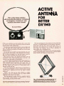
ACTIVE ANTENNA FOR DX'ing
Add gain to the loop antenna
never use a ferrite rod again
FIXING AUDIO AMPLIFIERS
Discover basic troubleshooting and repair techniques
using only a multimeter
PC ANALYZES AC NETWORKS
Compute AC node voltages with
our computer BASIC program
TEMPERATURE CONTROLLER
The budget way to solder a
joint with controlled heat
New
FactCards
This Issue
3
i
o
896 48
8
GERMSBACK
-';13..C411pr4
MAKEMEY
Do You REALLY Want to Make More Money?
Yes it does take work and a few sacrifices to
climb up the electronics ladder to where the bigger
money is. But, if that's where you want to be, then
work harder at learning
that's what you must do
and getting the right credentials, even if it takes a
-
few sacrifices. A B. S. degree and the knowledge
that rightly goes along with it can give you powerful
ladder -climbing equipment in your search for success in electronics.
The accredited Grantham non -traditional B.S.
Degree Program is intended for mature, fully employed workers who want to upgrade their electronics careers.
IN
ELECTRONICS
You say you're already trained in electronics
but that you're not making enough money ???
Well then, maybe you don't have an accredited
bachelor's degree to prove that your education
is up to snuffs Check out the Grantham Independent -Study B. S. Degree Program. It could
make a dollars and sense difference in your
electronics career.
Grantham offers this program, complete but
without laboratory, to electronics technicians
whose objectives are to upgrade their level of
technical employment. Since the field of electronics is so enormous, opportunity for advancement is always present. Promotions and
natural turnover make desirable positions
available to the man who is ready to move up.
Put Professional Knowledge and a
COLLEGE DEGREE
in your Electronics Career through
Independent Home Study
Study materials, carefully written by the Grantham
College staff for independent study at home, are
supplied by the College. Your technical questions
related to these materials and the lesson tests are
promptly answered by the Grantham home -study
teaching staff.
Recognition and Quality Assurance
Grantham College of Engineering is accredited by
the Accrediting Commission of the National Home
Study Council, as a degree -granting institution.
Grantham College of Engineering
10570 Humbolt Street
Los Alamitos, California, 90720
All lessons and other study materials, as well as communications between the college and students, are in the
English language. However, we have students in many
foreign countries; about 80% of our students live in the
United States of America.
This
booklet
FREE!
This free booklet
explains the
Grantham B.S.
Degree Program.
offered b independent studs to
those who work
in electronics.
for
Grantham College of Engineering
FREE
Booklet
CLIP
COUPON
and mail in
envelope or
paste on
postal
card.
H -10
10570 Humbolt Street, Los Alamitos, CA 90720
Please mail me your free catalog which explains your
B.S. Degree independent -study program.
I
Name
AgP
Address
City
L------
State
Zip
-
INCLUDING
12 -PAGE
Volume 4, No. 10
GADIGSit
October 1987
CONSTRUCTION
30
34
75
Grandpa's Antique Radio-make a radio that reflects the early 1920's
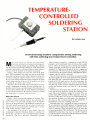
Temperature -Controlled Soldering Station-helps prevent the
destruction of delicate circuit elements
Active Antenna For Better DX'ing -an active loop can dramatically
improve long distance reception
39
59
64
67
81
FEATURES
ACNAP -put this
program to work analyzing AC networks, leaving yourself
free to handle the important stuff
Using Op -Amps In Power-Supply Circuits -understanding op -amps in
power -supply applications
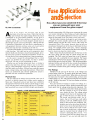
Fuse Applications and Selection -learn how fuses are used to protect
your electronics equipment and appliances
Servicing Audio Amplifiers -with nothing more than a multimeter, you
can repair your high -power audio equipment, while pocketing the change
Learn By Doing -op -amps are the most adaptable integrated circuits, but
you can't use them unless you understand them
HANDS -ON REPORTS
-a utility that manages Ram -resident software
80
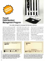
Persoft Referee Program
22
SPECIAL COLUMNS
Friedman on Computers-get
26
28
88
90
92
94
more out of your computer by stretching
your budget a bit to add hard -disk storage
Jensen on DX'ing-what country's flag is red, white,and blue; is governed
by a constitution, and is not the United States?
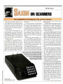
Saxon on Scanners -full spectrum capabilities come to scanners
Carr On Ham Radio-learn how the radiowave -propagation phenomena
lets signals originating in one hemisphere to be heard in another
Ellis on Antique Radio -Echophone EC1; the restoration continues
Circuit Circus -exploring voltage doubler /multiplier circuits illustrates how
high -voltages can be generated from low- voltage sources
Wels' Think Tank -reader interactivity continues, and you should see what
your fellow hobbyists have come up with
DEPARTMENTS
2
4
12
14
37
47
71
Editorial
-if
you don't tell us, how are we to know how best to serve you?
So, keep the mail coming
Letter Box -lets your words be heard
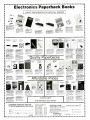
New Products Showcase -tomorrow's products are here today
Bookshelf-an information market for do- it- yourselfers and professionals
FactCards -we give you nothing but the facts
Gadget -the newsletter for grown -up kids
you need more information about a future
Free Information Card
-if
purchase, the manufacturer is the one with the answers
Fuse Applications -page 64
t_
J
Volume 4, No.10
October 1987
The Magazine for the Electronics Activist!
Larry Steckler, EHF, CET
Editor -In -Chief & Publisher
In the mail bag!
We get the most unusual mail at our office. The distribution of
the various types of communications vary from the "absolute
junk mail" to the reader who is responding to an item in a recent
issue of the magazine.
The junk mail is claimed to be "astronomical" by the mailroom
staff. That does not make our job easier, because we read it all!
Trade and professional magazines fall into this category; find
them very valuable. Magazines intended for engineers, scientists, and manufacturing specialists reveal what the trends in
consumer buying activity will be from three months to several
years from now. For example, back in 1977 forecasted a two billion dollar consumer computer marketplace. (That's pre -IBM
PC!) Yes, was laughed at. Today, that sum is a drop in the
bucket.
Other mail informs me of new scientific developments, new
products, buying trends, trade meetings and shows throughout
the world, and, of course, financial reports from successful companies. The latter sold my father on a dinky little company that
sold a Polaroid camera back in the late forties. This mail is
valuable, because it tells us, provided we are perceptive enough,
what will happen to our hobby industry in the future.
I
I
I
And, of course, we receive lots of reader mail. We have all
sorts of readers out there, from whom we get a corresponding
diversification of ideas, complaints, suggestions, almost all the
articles you see in this issue -you name it, we read it! And, it's in
the reading of your mail that we form in our minds the composite
voice of you. We get to know you better than some Madison
Avenue huckster's readership survey would presume.
We have only one fault with the mail -it's the volume. We
cannot hope to answer every letter sent to us. Some we do, most
require no answer. Many letters are grouped and presented in
our Letter Box column with comments from our staff; we answer
many letters that way.
Nevertheless, we want you to write. Your response (letters) to
our actions (magazine) makes for a better Hands -on Electronics. Please give us a hand.
Art Kleiman, editorial director
Julian S. Martin, KA2GUN, editor
Robert A. Young, associate editor
Herb Friedman, W2ZLF, associate editor
John J. Yacono, associate editor
Brian C. Fenton, associate editor
Carl Laron, WB2SLR, associate editor
Byron G. Wels. K2AVB. associate editor
M. Harvey Gernsback, contributing editor
Teri Scaduto Wilson, editorial assistant
Ruby M. Yee, production director
Karen S. Tucker, production manager
Robert A. W. Lowndes, editorial
associate
Marcella Amoroso, production assistant
Jacqueline P. Cheeseboro, circulation director
Arline R. Fishman, advertising director
BUSINESS AND EDITORIAL OFFICES
Gernsback Publications, Inc.
500-B Bi -County Boulevard
Farmingdale, NY 11735.
516/293 -3000
President: Larry Steckler
Vice- president: Cathy Steckler
NATIONAL ADVERTISING SALES
(For Advertising Inquiries Only)
Joe Shere MIDWEST /PACIFIC
1507 Bonnie Doone Terrace
Corona Del Mar, CA 92625
714/760-8697
Larry Steckler, Publisher
500 -B Bi- County Boulevard
Farmingdale, NY 11735
516- 293 -3000
Cover photograph,,,
Herb Friedman
Composition by
Males Graphics
e...)
.
Hands-on Electronics. (ISSN 0743-29681 Published monthly by
'7iernsback Publecalans. Inc 500 -B BI- County Boulevard. Farm ugdale.NV11735 Second-Class postage paid at Farmingdale. NV
and al additional mailing offices Oneyear. Iwehe issues. subscnpnon rate U S and possessions $28 00. Canada 833 00. all other
ounines $35 50 Subscnpeon orders payable In U 5 funds only.
International Postal Money Order or check drawn on a U S. bank
U S single copy price $2 50 c 1987 by Gemsbaok Publications.
Inc All rights reserved Ponied m U S A
Postmaster Please send address changes to Hands-on Electronics, Subscription Dept PO Bon 338. Mount Morns. IL
51054 -9932
.
stamped self- addressed envelope must accompany all submitted
manuscripts and or artwork or photographs if then 'alum Is desired
should they be reiecmd We disclaim any responsibility for the loss
or damage of manuscnpts ender artwork Or photographs wale in
nu, possession a otherwise
A
Julian S. Martin, KA2GUN
Editor
2
Asa service to readers. Hands-on Electronics publishes available
plans or mlo,matlon relating to newsworthy products. techniques
and scientific and technological developments Because of possible vanances in the quality and condition of materials and workmanship used by readers. Hands-on Electronics disclaims any
responsibility in, the sale and proper tunctgning el reader-bulk
prefects based upon or from plans or information published in this
magazine
Increase your knowled8e about all aspects of electronics
An absolutely no -risk guarantee.
6elect
5
Books
For only $3y5
and get
Free Gift!
a
values
to
$135.70
--, _
ElEAnve
N
S
.
SOUND
BUILD
PIOIECIS FOR
BUILD
RECORDING
BUDGET
LIMNING RECTION(
THEORY
A PERSONAL
ICRtIIMOCÉSSOR
EARTH STATION
CONTROLLED
FOR WORLDWIDE
SATELLITE TV
IBER EpBNMENT
RECEPTION
---
2839
$15.95
2635
1532P
519.95
1977
$14.95
$26.95
1531P
2758
511.50
$24.95
THE MASTER
POWER
CONTROL
ELECTRONIC
DESIGN AND
CONSTRUCTION OF
ALTERNATE
ENERGY
PROJECTS
LISTENER'S
PRACTICE
MASTER
SOLID-STATE
HANDBOOK OF
IC CIRCUITS
SHORTWAV2
PRINCIPLES
1/AEIOIO-
IMPEDANCE
,D ioriD.
IC
DEVICES
COOKBOOK
1672P
$12.95
1665P
$17.95
1250P
EASY
-0ULD
.
1599P
$14.95
2755
$16.95
$17.95
Elementary
Electricity
Electronics
L.....
.Áe4.00,
-
$23.95
517.95
2725
2655P
$21.95
$26.95
Big Savings. In addition to this introductory
offer, you keep saving substantially with members' prices of up to 50% off the
publishers' prices.
Bonus Books. Starting immediately, you will be eligible for
our Bonus Book Plan, with savings of up to 80% off publishers' prices.
Club
News Bulletins. 14 times per year you will receive the Book Club News, describing all the current selections- mains, alternates, extras -plus bonus offers and
special sales, with hundreds of titles to choose from.
Automatic Order. If you
want the Main Selection, do nothing and it will be sent to you automatically. If
you prefer another selection, or no books at all, simply indicate your choice on
the reply form provided. As a member, you agree to purchase at least 3 books
within the next 12 months and may resign at any time thereafter.
Ironclad NoRisk Guarantee. If not satisfied with your books, return them within 10 days without obligation!
Exceptional Quality. All books are quality publishers' editions
especially selected by our Editorial Board.
Reference Guide to Electronics
Manufacturers' Publications
-a time- and money-saving list of
2792
1370
$16.95
(Publrshers Prices Shown)
FREE when you join!
11111
2753
1586
$16.95
ELECTRONIC
PROJECTS
notaurraoren
$14.95
1199P
Membership Benefits
DIGITAL
ELECTRONICS
1529P
2795 $29.95
Counts as 2
72EP
$21.9.,
$10.95
1693
THE COMPLETE
521.95
BASIC
BATTERY
Ndn,rnr r:uidr
/I,.ir......
Hanufurur,i.
product literature from all the
major electronics suppliers.
1I.I1,
(a $6.95
value)
.1110T
1
El ECTRONICS
ELECTBIDES EIUK CLJB
THEORY
P.O. Box 10, Blue Ridge Summit, PA 17214
Please accept my membership in the Electronics Book Club and send the 5
volumes listed below, plus my FREE copy of Reference Guide to Electronics
Manufacturers' Publications (2683P), billing me $3.95 plus shipping and handling
charges. If not satisfied, may return the books within ten days without obligation
and have my membership cancelled. agree to purchase at least 3 books at regular Club prices (plus shipping/handling) during the next 12 months, and may resign any time thereafter.
I
I
1757
1604P
524.95
1775
$15 95
529.95
Counts as
NYKEL fNODraIL AND
WANING
501 ID.STATT TVS
2
KOPPEL
IC CIRCUITS
117
PRACTICAL
IC PROJECTS
YOU CAN BUILD
rA>
Name
Address
City
State /Zip
2707
All
$24.95
1925
2645
$24.95
1987 ELECTRONICS BOO( CLUB. Blue Ridge Summit, DA 17214
books are hardcover editions unless numbers are followed by a P
CIRCLE 10 ON FREE INFORMATION CARD
for
$18.95
paperback
Phone
Valid for new members only. Foreign applicants will receive special ordering instructions. Canada
must remit in U.S. currency. This order subject to acceptance by the Electronics Book Club.
RESP -1087
L_JLJ
D
D
Hands -on Electronics, 500B Bi- County Boulevard, Farmingdale, New York 11735
Sedition, Abstraction,
Uglification, & Derision
On page 78 of the July 1987 issue
shouldn't the answer for the differential
amplifier in Fig. 8 be +36 volts instead
of -13? As the text states, the sums of
the inputs are calculated algabraically.
As far as know a + 7 minus a + 3
equals + 4. Then
I
E0= 9x4 =36
I'm not approaching this properly,
please set me straight.
-W.J.D., Upland, CA
If
Part of the problem you're experiencing isn't with math, it's with the subscripts. You are subtracting E2 from E,,
instead of subtracting E, from E2. So, 3
minus 7 equals -4. Multiplying that by 9
does yield 36 as you say, but a negative
36. Thanks for the correction.
[For those of you interested, the heading for this letter was taken from 'Alice In
Wonderland."]
Idea Potpourri
would like to see some more home brew projects that would be helpful on
the test bench, like a stable function
generator, and possibly a triggered
pulse generator. There are plenty of logic
probes in kit form already, but perhaps
you could throw one in to help complete
my digital lab. have copied such projects from some TAB books and several
other books I have collected or checked
out from my local library. Some of circuits and specifications are rather old in
design and components. So, I thought
you guys might be able to come up with
better circuits and innovations of the day.
Anyway, thanks for the last hold out
from total computer saturation. How
about some ham -radio stuff? I think that
Packett Radio is something that even the
computer fans of your magazine would
enjoy. Thanks for your time.
-P.F.C., Paris, KY
I
I
We'd like to see more of everything!
The Great PC Clone Contest is still on,
so get those manuscripts in. Whether it's
about serious test equipment, fun projects, or information for the fast times we
live in, send us your stuff! Just think, not
only do you get paid upon acceptance,
get a chance to see your name in print,
and have a go at winning a computer, but
you also get to share your ideas. Who
could ask for more from a hobby?
Hanging On
read in one of your other magazines
(I forgot which issue), you had a musical
hold button that readers could build for
their phone using something from a Hallmark card. I'm really interested in that
device. Unfortunately, can't remember
which issue it was in. I would really like to
have an electronic hold button so that if I
put a phone on hold on, any of my
phones can go to any other phone and
pick up at that phone instead. I don't
want to worry about the hold button still
being on and having to speak from that
phone or having to turn it off as soon as I
hang up.
Could you please send me some information on it that would help me to design
it for my house, and probably assist most
of the readers out there with an interesting and useful project.
-J.K., Newton, NH
I
I
I
The issue in question was September/
October of 1986. The project you mention will operate as you desire. To turn
the hold off, just pick up any extension
phone. That should hold you for a while.
terminals are actually used for each
switch, so familiarize yourself with the
terminal layout and try again. Good luck.
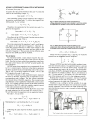
From High to Low
Regarding "Electronic Fundamentals'
in the March 1987 edition of your magazine, on pages 84 and 85, please clear
something up for me. On page 84 Fig.
12B and Page 85 Fig. 15B. Shouldn't the
diagrams be reversed. I understand the
outputs of low -pass filters were taken
from across capacitors. Looks to me like
the diagram in 12B shows the output
taken across the resistor.
Also in 15B, which is supposed to be a
high -pass filter, it looks like the output is
taken across the capacitor instead of the
resistor. Could there possibly be a mixup
of the figures, and should they have
been reversed? Perhaps do not understanding the definitions of the cutouts of
LPF and HPF circuits.
I would appreciate your clearing that
up for me and I thank you. I'm a subscriber to your fine magazine and look forward to each issue.
-W.J.D., Urbane, AL
I
You're right about the mix up, the figures were transposed. Both filters got
passed us which indicates the need for a
filter filter so any high -pass will show our
high class. Thanks for pointing that out
(and I hope this reply didn't cause too
many groans).
Coiled and Ready
have a copy of the September /October 1986 Hands -On Electronics. The
story that intrigued me the most was
"The Ultimate Burglar Alarm," by Byron
G. Wels and Robert M. Wolet. tried to
construct the device, but the diagram
shows a transformer that the story does
not mention. My question is "What size
is that transformer ?" or, "What .am
doing wrong ?"
-M.L., W. Des Moines, IW
I
I
The item you call a transformer is the
coil for the relay, Kl. It is contained inside
the relay housing, as is indicated by the
dotted lines. The relay should have at
least eight terminals: two for the coil and
three for each switch. However, only two
Head Case
built a "Fred- the - Head ", and although not completed, his mouth, eyes,
and microphone pick -up work fine. His
I
eyes really do light up!
modified his mouth circuitry and I'm
constructing an FM- wireless transmitter
so I'll be able to hear anyone who wishes
to talk to me from a short distance. Can
you imagine the effect-carrying on a
conversation with that wooden head?
I
-R.E.C., Atoka OK
It's a great way to keep the kids busy. If
anyone else out their has come up with
an interesting twist for any of our projects, please let us know.
DO YOU
REALLY
GET THE BEBT BUY
FROM
T H EM?
et 's face it: There will always be some outfit
that can undercut a published price. They
do it by having no overhead, and no
responsibility to you, the consumer.
"So, you want that Jerrold 450
combo'? The one that hone CON
Co.. lit. is offering for $19900'7
Well, that's a good price, but
here's what I'll do..." What may
happen is that you may save a
couple of bucks at the time. But suppose
there's a problem (and it happens to the best
of them,) and you call that "Dealer "... This could be what you'll hear
"No, Steve isn't here. He moved out, the bum! And he owes me $43700 on the phone bill! No, don't
know about any guarantees on your Gerald, who's that'? Listen, if you see that creep..." etc.
At PacMc Cable Co., you've got an established company who will be here for you, time after time We may
be tough competitors, but we've
got a soft spot for our clients! Try us, and be treated right -and we'll prove it by giving a one -year warranty
on everything we sell.
Check our prices on Scientific Atlanta Units!
I
ITEM
RCA 36 Channel Converter (Ch
output only)
Panasonic Wireless Converter lour best buy)
400 or 450 Converter (manual fine tune)
Jerrold 400 Combo
Jerrold 400 Hand Remote Control
Jerrold SB- Add -On
'Jerrold SB- Add -On with Trimode
M -35 B Combo unit (Ch 3 output only)
M -35
3
Combo unit with VanSync
Minicode (N -12)
B
CHECK US OUT -WE'LL
MEET OR BEAT THE OTHER'S
ADVERTISED WHOLESALE
1
10 OR
UNIT
MORE
2900
18.00
ITEM
1
UNIT
Minicode (N -12) with Van Sync
Mimcode VanSync with Auto On -Off
88.00
69.00
8800
16900
119.00
29.00
18.00
8900
58.00
Econocode (minicode substitute)
Econocode with VanSync
MLD- 1200- 3 (Ch .3output)
MLD- t200 -2 (Ch 2 output)
99.00
70.00
Zendh
Interference Filters (Ch.3 only)
*Eagle PD -3 Descrambler (Ch 3 output only)
Scientific Atlanta Add -on Replacement Descrambler.
69.00
99.00
70.00
10900
75.00
8900
58.00
Quantity
6200
105.00
52.00
Price
Each
5600
99.00
58.00
9900
58.00
125.00
175.00
Output
Channel
Item
9900
145.00
7900
8900
SSAVI Cable Ready
10 OR
MORE
24.00
14.00
11900
11900
65 00
7500
TOTAL
PRICE
OR RETAIL PRICES!
MasterCard
VISA
SUBTOTAL
Californ a Penal Code 8593 -D forbids us from
shipping any cable descrambling unit to anyone
residing in the state of California.
PLEASE PRINT
73251/2 Reseda Blvd., Dept. H -10
Name
Reseda, CA 91335
(818) 716 -5914 (818) 716 -5140
Address
IMPORTANT When ordering, please have
the make and model number of the equipment
used in your area -Thank you!
COD 8 Credit
Cards -Add 5%
Prices subject to change without notice
Pacific Cable Co., Inc.
NO COLLECT CALLS!
Shipping Add
$300 per unit
State
-
City
Zip
Cashier's Check
Acct
TOTAL
Phone Number
I
Money Order
C.O.D.
Visa
Mastercard
Exp. Date
a
Signature
Prices subject to change without notice
FOR OUR RECORDS
DECLARATION OF AUTHORIZED USE
I. the undersigned, do hereby declare under penalty of perjury
that all products purchased, now and in the future, will only be used on cable TV systems with proper
authorization from local officials or cable company officials in accordance with all applicable federal and
state laws.
Jerrold is a registered trademark of General Instruments Corp
Dated
'Call for availability
-
Signed
5
D
D
OFF
V
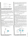
RS -422A to Loop Converter
To meet increasing demand for high
V
a00mV
10A
300mA
-1':;t?':
COM
performance, low cost RS -422 interface
equipment, B & B Electronics has introduced the new RS -422A to Current Loop
Converter. The Current Loop Converter is
bi-directional and optically isolated. One
channel accepts RS -422A data and output
current loop; the other channel accepts
current loop data and outputs 422A.
A male DB25P connector is used for
the current -loop interface and a female
DB25S connector is used for the
RS -422A interface. The unit requires 12
volts DC at about 100 mA and can be
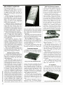
includes a maintenance -free gel-cell battery, regulated battery charger, alarm with
reset, and is housed in a cabinet that will
fit into any environment. No installation
is required, just plug it in. With its 26
CIRCLE 60 ON FREE INFORMATION CARD
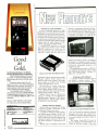
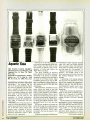
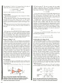
Good
as
Gold.
The 70 Series Multimeter: The Shining
Standard By Which Others Are Measured
These multimeters give you solid value for
your money. A 3 -year warranty keeps you from
paying the price over and over for lesser quality
CIRCLE 59 ON FREE INFORMATION CARD
purchased with an optional power supply
(Model 422PS) which powers the
holding readings. Audible tones for continuity
checks. Autoranging for simple operation.
Uncompromised quality at competitive
prices. Get your hands on a 70 Series Multimeter
at leading electronics distributors nationwide. Or
of the isolators. No further
power supply is needed if the existing
current -loop interface is active.
The RS -422A to Current Loop Converter model 422CL is priced at $44.95;
Power Supply Model 422PS for the converter is $14.95; The Loop Current Power
Supply Model 422PS is $14.95.
Further details may be obtained by
call toll free 1- 800 -227 -3800, ext. 229 for more
writing or calling:
RS -422A side
meters.
Choose from either the basic 73 or the
feature-rich 75 and 77. You'll find the features you
need at the price you can afford. Touch Hold° for
information.
FROM THE WORLD LEADER
IN DIGITAL MULTIMETERS.
FLUKE
ampere-hour battery, the BC -325 supplies
60 minutes of emergency power at half
load and 25 minutes at full load, allowing
for the safe, comfortable shutdown of a
computer system.
The suggested retail price is $479.00.
For additional information contact Tripp
Lite, 500 North Orleans, Chicago, IL
60610; Tel. 312/329 -1777.
Computer with Software
A computer without software is like a
car without a battery- useless! That's
why Vendex Pacific Inc. has bundled five
B & B Electronics
Manufacturing Company, 1500P Boyce
Memorial Drive, PO Box 1008, Ottawa,
IL 61350: Tel R15/434-0846.
Battery Back -Up System
73,75,77
Need a back -up to handle both shades
warranty
$79. $109. $145
3 -year
0 7 %. 0 5%. and 0 3% basic dc accuracy
Audible continuity (75 8 77)
Analog/digital display
Range hold (75 8 77)
Wits. afros. 10a diode lest
Multipurpose holster (77)
Autorange
Touch Hold tuncbon (77)
2000+ hour battery lite
FLU KE
©1987. Fluke
CIRCLE 14 ON FREE INFORMATION CARD
of electrical trouble- brownouts
as well
blackouts? Read some more.
In addition to offering complete protection against power failures, the BC -325
features full brown -out protection and a
built -in filtering network that guards your
equipment against transient spikes and
line noise whenever it's operating on AC
as
power.
The BC -325 is a complete system that
CIRCLE 62 ON FREE INFORMATION CARD
of the most frequently requested software
packages with every new Vendex Turbo- 888 -XT computer, allowing the user to
be up and running in literally a matter of
minutes.
The Vendex Turbo-888 -XT comes to
the user complete with 5I2K RAM; a collection of discount coupons worth over
C
r
CYC
O
CORPORATIONZ
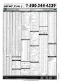
1- 800 -344 -4539
.m
MIMI
Ta
`
E.
F. JOHNSON ATLANTIC SEMICONDUC'
11/T
NAM
216
imiggEs=mamm
4o11'M..
SOLDER TAIL
DIP SOCKETS
44
40
S%
F1i
i0M.,
ao
410
ARIESLPLESSEV
CHEMICADLS
now
r-
ton
Cm
::
mm
ñ
40107
M
..
.,
..
10
.1111
x
.....,,....
.m am.44...,...._.
0
V
716
107
:3617
1
lßm
'
...
i..
mé
,
o-
wM
,wr
]110M
,.
.
CMOS
00
0
.0.-...: °'
pia
011
w.
,
,.
...r
/OM
.
..
-..
..
-.
0.0. 0.1.44
ir45a
11
eww..
4.12
.w...11u1
1. 1110.0440111.
1. ,.
w
.1
..,
ww
4.
w,
wt..,
aM
.
w
a.s
os
]
we
.44.0.04
1e
101
14.
I}
011
.,
a
-
,
.
am36e4y36MRYe4..r.....-
u.ou
w5
-
moons, o
1111
..
.
.
..
..
..
-
l
Ca.
prS(T6'
DISC
,
1113 CO
71
7 10
22 SO
241,11
41
4
33 75
171
'.
,..,..
...w
i.
C
10
14
1
0
.
,
a
,.°rM
s
R
r
e
'.
.
41.3 CO
411
1
C4
...........a........ra...+r,
.fav
ww
s1.M
rM ...
V,
.
t.
PANASONIC LS SERIES
...ns.n.w
0
561
e
r..
o
CAPACITORS
"
1in..
03
03
SOO
o
,
w
,
00
561
io
1
.
GOO
PO
0
Metal Film Freed Resistors
Av,,s,.
.,
MO
/
1"r..
r.vs
1
WO of
;
OU440711
1
A
03
,
,...au
.Mi
.
367
.
wd... ..
31110.
.
404 4.4.014
Tt
1,.4
120
,
,.
.
er.,r.e.tG.
mry
rt,
S.,
1 10
E.f
WIRE WRAP
DIP SOCKETS
.
.
wwM
20
I
9107518982 DIGI REV CORP
X
-
.
.._.
TW
ESDECWIND SDTRESÁMOEK GRE.
04.
an
.
m
T
..
HIM
216.681.3380
ón ,,R,..,.:!..., e
10 O.
C14001
144
FAR
na
---___
rt0.11.
r
401211
rra
62927914
C_rbon
,. i
.....----74-41r----
s.,,_
.
Teles
6674
4181
DRAM 150NS $5.7011; $39.9519
Factory Firsts
x 1)
`^]"
INTEGRATED CIRCUITS
MN
256K 1262,144
NJ W MILLERAAVIDENGINFI'rl`.r.
EACMNC
AN, Puerto Rico
)
713
1
40
00 oc
xb
.
.
.
43
33
0
PS
DM
70
7
2
PO
77
14
77
..
...r
,
...,
,
'
70 00
..n
ID
!r
n
..,
,.
47
p0
034,
ne
.
41661M,,.
..
.
,
.
.
NC
LA
1101.111011,
Chi..
.
orn
.
....
.
-
,
AuO
Tr* TS AI
10720
NEC
-
41101
.
,
,
450
n
.
...
.
ÿiw.N
pa
io.
S
1
non
no
20
rr
m
-
.11
T
0p
...ono
e
i714
s
ten no
m.
no
m.
.u,.low
m
w.
r
....
1,.00
rem
n 11
11
A
41
0
a
91
1
UM
16
33
15 43
Ill 17
0
173
0
ran
14 17
CAt
ma
_,
_
/496
1
PANASONIC V-SERIES
70 40
.;
r
rv
.44,rrM.
.4
o..r.n.
v.
...
..0
.
r.. ....
.
0.1.10.1.1.11101
.200.
rer.
Am..
.
m
..
t.ww
,
,m
10.
v.36
Ion
oom uo
I
oc,
62
.
c.w,w.
71
11
1
..
.
...
3]5
r
a
43
46
0
r.
l
1101
SSW
a5
1 IS
0140
.,
r
0
g
711
V
Al
CO
40
077
roo
m36
1
rolad
.tr ,w,..n
.....
nrr
r.
74
'
e...,,PTO.
N00CC'
..N r_
cA.acnoellpe
I
I
U
0.00 .5 9.99
29.00 -149.99
50.00- 399.99
$1000&Up
4432
0 34
36
130 70
161 AD
73
3110
01.20
1w
, n
1*SC
7
No
P679p Kn
oAttY
939II
SERVICE CHARGES
910.00.929. o0
4
_
7
NI 20
13570
,
ovwfp
.
8 ON
V
1
,
s
'
CIRCLE
37
'...'..'........................r.
111104.
.
°
MI
0 013
0 022
.
PRICES SURJECT TO GRANGEt WITNOUY
71
.
.
I.
.nn nono nog .,ro.,,
01
D
10
r..u..
G
10
II
012
AO
,
Mao
110
210
Key rda,r10
,a,
,.trennin, win.,, nor.
047
AO
.
doom. on 1wnc. canon an .,nn,. tofo, Mow nom .old by Dap K.r nee W conAe.d for wan. 0.0101 hom tat o. roo crewman. we noon., en...
ND tono r6 oa Iwo .anear. Aher mor, to,,, won total .. of e,e encounter. emu ern
die .wogewe *count To 1M subaqua.
the ron dnouren. awns Then a* the .once
too, We on non ,p and mania. to anease., n the L S A Canana on Meco non,.Por
tacs or ,honer ado GCCOno.n,. ordo Dp-a.y eon .0P sinews loner, d. commensal, S Anna.
Mena. Canna and Meso
YINFS M0ER8G IT PROSE. GAL 1118 344 4535 IAK. 0.11 216 611 65741 ST MAIL BESE TIM MU TI: IIIFIIET. P.S.
877. TAM River WAIN 14781.
Vier inn an 4r
nney orno Mesta. Ca,9e etSA or C 1l :l DIGI AEY GUARANTEE: A
evo Dea an tat pow to to delecnre .d W not.. or relwd
The
1137
7 74
.10]
°°"
PO
'..
.
..
..
.
.423
....
S
CO
Chipe
n
..
.
.
.
::,.
00
sa
M,croqxesstr
20
e
A Si
54 Cc
.5
...
'
sA.rir
36711
76
,
í4M:.
16
1III1..,
N.....
..
60
7''7rE.71',71-7.-
.r
70.
'5495
rw. r.....t
,.
L5
n.
IC=1
mw
..
0
r
VOLUME DISCOUNT
Add $2.00 9
0.00 -1 99.99...
Add 90.79 5 100.00 -$24999
Add 50.50 4 250 00.1499 99
Add $0.29 S 500.00 5999.99
No Char e 11000A Up
NET
Less
10
less 19
less 20'
.
Loss 15
FREE INFORMATION CARD
7
NEW PRODUCT SHOWCASE
Bookshelf Loudspeakers
$1000 towards future purchases; and highquality software that includes a word processing program, a spreadsheet, a data
base, a computer training program, an
assortment of RAM resident pop -up programs, and the Vendex HeadStart Oper-
You may want to take these off Bose's
shelf and put them on yours. Especially if
ating Environment.
12
Enhancements to the hardware include
a
high -speed Intel 8088 -2 micro-
processor, that operates at either 4.77
MHz or 8 MHz; clock and calendar circuitry, with a battery backup system so
that the clock and calendar are always
operating; two standard 360K floppy disk
drives; seven standard IBM compatible
slots; and a high-resolution graphics card
that is compatible with monochrome,
Hercules, and color-generated graphics
at no additional charge.
At a starting price of $995, it also
comes with with a high -resolution TTL
green-screen monochrome monitor.
Bundled with the Turbo -880-XT are
The Executive Filer from Paperback Software, MyCalc from Software Tool Works,
the All Interactive Trainer, and a custom
version of HOT, the Desk Top Manager
from Executive Systems.
At no time does the consumer have to
read or study a manual. ATI, an interactive training program, will take the user
through all the computers's functions and
capabilities. In addition, each software
package is color coded and identified by
Vendex's Headstart Operating Environment, which makes using the Turbo -888XT a breeze by leading the user through
the computer's operations on a one key,
point and select basis. All the user needs
to do is move the cursor to a selection and
press the help key, which will then give
them on -screen information to proceed.
Every Headstart menu is presented in
clear and simple English.
HeadStart also provides and gives the
user control of custom utilities that include Custom Diagnostics, all disc and
file utilities available through MS -DOS
(i.e., Copy, Format, Check Disc and
Erase, DOS help screens, and printer utilities that enable the user to set up the
printer default for the specific printer
being used). In addition, Head Start
provides a utility program for the advanced user that will explain the powerful
commands of MS -DOS.
The Vendex Turbo -888-XT will accommodate the most popular accessories,
because a parallel port, a serial port, a
game port that can accommodate two
joysticks, a floppy controller capable of
handling four floppy disk drives, and an
additional port (to attach a mouse, if desired) are built in. The unit will also accept
an optional hard -disk drive.
For further information contact Vendex
Pacific, Inc., 40 Cutter Mill Rd., Suite
438, Greatneck, NY 11021.
-
you're seeking good performance from
small speakers, at a modest $299 per pair
suggested list price. The speakers measure IO x 15 x 7 inches, and weigh only
pounds each.
Like the other models in the series, the
2.2 loudspeakers feature innovative technology for precisely controlled sound radiation, allowing listeners to hear
balanced stereo from nearly anywhere in a
listening room called the Stereo Targeting
system, that new technology is used in all
Point Two speakers. A driver array, designed in conjunction with the speakers'
cabinet and crossover network, directs
sound into the middle of the room.
As a listener moves toward one speaker,
its loudness actually decreases relative to
CIRCLE 64 ON FREE INFORMATION CARD
All tools are made of high -quality carbon steel, with heavy chrome plating, for
long life and top efficiency. Dielectric
tools permit adjustment and repair of
"live" equipment without stopping operation-the most practical and economical
way to service equipment. It comes with a
leather zippered case engineered for maximum protection of each tool, ensuring
long lasting performance. The case is
compact for easy
CIRCLE 63 ON FREE INFORMATION CARD
that of the other, so that they remain in
balance.
The speaker's directional characteristics, combined with its controlled
output, allow maintenance of a stable stereo image regardless of where the listener
sits or stands. Consistent performance is
assured by Bose's exclusive Syncom II
computerized driver testing and matching
system.
In addition, an advanced bass- tuning
technique adds full -frequency realism by
precisely controlling an air cushion inside
each speaker cabinet. The result is deep,
realistic sounding bass -without a large,
bulky cabinet or extra amplifier power.
The system configuration will produce
both high -fidelity stereo and video sound.
Other Bose Point Two loudspeakers are
the 10.2 (suggested retail $1199) and 8.2
($949) floor standing speakers and the 6.2
and the 4.2 bookshelf systems ($599 and
$419 per pair, respectively).
For further information contact Bose
Corporation, The Mountain, Fra-
portability- eleven
inches long, six inches wide.
The kit includes: 2 spring adjusters; I
armature hender; I spring tension gauge; I
four-way tool; I thickness gauge; I cleaning spray, I duck -bill plier; I inspection
mirror; I pen -type contact burnisher; 12
burnisher blades;
I
screw driver;
I
tweezer; and I selector- switch brush.
The kit model #K -55 is priced at
$54.00. For further information and literature write to: Jonard Industries Corp.,
134 Marbledale Road, Tuckahoe, NY
10707.
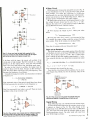
Racing Pulse
Your heart may skip a beat over this
pulse generator with repetition rate variable from 1Hz to I25MHz and a choice of
fixed 2 -, 1.5 -, or -ns risetimes. The
PM5785 has a wide choice of external trigger and -gate functions, full control of
1
:-
?w40.
IF
W:
_. d
-
-
fi..
,,,
..-.
'Er
;A
* __,___-
-
4
CIRCLE 65 ON FREE INFORMATION CARD
mingham, MA 01701.
Relay Servicing Tool Kit
This may be the transistor age, but relays are still around, so Jonard created a
I5- piece, precision relay tool kit containing a carefully selected group of tools
for use by the electronic and telecommunications industries. The kit contains
tools necessary for adjusting, servicing,
and calibrating all types of relays.
pulse repetition rate, duration and delay, a
presettable, high -speed burst option, and
dual normal /complementary output with
a choice of bipolar, positive or negative
pulses. Setting error indicators simplify
operation.
The choice of fixed, high -speed transition times and output -pulse forms makes
the PM5785 very well suited to a wide
(Continued on page 12)
train with NRI for a high paying
career servicin co
SANYO COMPUTER- 84)88
CPU double-sided disk drive,
256K RAM, 4.77 MHz and 8
MHz turbo speed.
DIGITAL MUI.TIMETERProfssknal test instrument
for quick and easy.
uters.
MONITOR -High resolution,
green screen displays, crisp
text and graphics.
measurements.
TECHNICAL. MANUALS
-with complete specs on
Sanyo computer and
professional programs.
LESSONS- Clear, well illustrated
texts build your understanding
of computers step -by -step.
DISCOVERY LAB -Using it,
you construct and test
circuits like those used
with computers.
DISK SOFTWAREincluding MS-DOS, GW
BASIC, WordStar,
and CalcStar.
DIGITAL
LOGIC
-
PROBE
Simplifies
analyzing digital
circuit operation.
Get started now by building this
fully IBM PC compatible computer
Now you get it all... training for America's
fastest growing career opportunity ..
training to service all computers ..
training on the newest total computer
system, the Sanyo 880. Only NRI can give
you the well-rounded training you need,
.
.
because only NRI gives you a complete
computer system ... computer, monitor,
disk drive, software, even test instruments
like a digital multimeter and logic probe to
work with and keep. It all adds up to
training that builds the knowledge,
competence, and ability you need to
succeed as a computer service specialist.
Get inside the newest, fully IBM PC
compatible Sanyo Microcomputer
As an ti RI student, you'll get total
hands-on training as you actually build
your own latest model Sanyo 880 Series
computer from the keyboard up. It's fully
IBM PC compatible and, best of all, it
runs programs almost twice as fast as an
IBM PC. As you assemble the Sanyo 880,
you'll perform demonstrations and
experiments that will give you a total
mastery of computer operation and
servicing techniques. You'll do programming in BASIC language -even run and
interpret essential diagnostic software.
Understanding you get only
through experience
You need no previous knowledge to
succeed with NRI. You start with the
basics, rapidly building on the fundamentals of electronics with bite -size lessons.
You perform hands -on experiments with
your NRI Discovery Lab and then move
on to master advanced concepts like
digital logic, microprocessors, and
computer memories.
Learn at home in your spare time
You train in your own home at your own
convenience, backed at all times by your
own NRI instructor and the entire NRI
staff of educators and student service
support people. They're always ready to
give you guidance, follow your progress,
and help you over the rough spots to keep
you moving toward your goal.
100 page free catalog tells more...
send today
Send the postage -paid reply card today
for NRI's 100 page catalog that gives all
the facts about computer training plus
career training in robotics, data communications, TV /audio/
video servicing, and
many other fields. If
the card is missing,
write to NRI at
the address
below.
MHOOLS
McGraw -Hill Continuing Education Center
3939 Wisconsin Avenue
Washington, DC 20016
Irr' i,
-
We'll give you tomorrow
11
NEW PRODUCT SHOWCASE
(Continued from page 8)
range of digital applications in research,
production or service. The 2 -, 1.5 -, or Ins risetimes are equivalent to 1.4ns, Ins,
or 700ps for ECL work, (with 20% to
80% of pulse- amplitude, transition -time
definition).
Output impedance back-matching absorbs more than 95% of reflections from
mismatched loads, to provide very clean
pulses under practically all conditions.
There is a choice of four output -level
ranges from 0.2 to 5 volts to match different circuit requirements.
Triggering, duration, and gating can all
be controlled externally. External triggerslope and level controls allow synchronization with an external clock. External duration control enables the unit to
function as a signal conditioner. An external gating control makes it possible to
provide synchronized bursts of pulses.
Careful circuit design, has made it possible to provide a burst option presettable
from I to 9999 pulses. The number of
pulses is set directly on the front panel and
can be triggered manually or remotely via
the external input.
Time -setting error indicators confirm
correct setting of repetition rate, pulse
duration, and delay. Pushbutton selection
simplifies output -pulse choice with no
time -consuming adjustment of inverter
and/or offset controls, and a complementary switch allows instant inversion of the
output without exchanging cables.
Prices for the PM785 start at $3,385.
For more information contact Philips Test
and Measuring Instruments, Inc., 85
McKee Drive, Mahwah, NJ 07430.
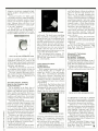
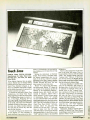
Real -Time Spectrum Analyzer
Here's a unique combination of spectrum analysis and digital oscilloscope
utilizing the versatility of any IBM PC,
XT, AT, or compatible computer allowing
the user to view both the input signal and
its frequency spectrum in real time.
Useful anywhere spectrum analysis or
event recording is needed. the digital oscilloscope features: 4 channels of simultaneous acquisition; 500KHz sampling rate
per channel; 32K data buffer per channel;
full pre and post trigger (up to 32K); triggering in: analog, digital, external, internal, and single -shot mode; grid display;
lissajous plot of X vs. Y using any combination of the 4 channels; print -screen
CIRCLE 66 ON FREE INFORMATION CARD
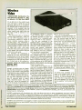
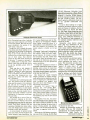
learn any function that's on the original
remote control unit. And with 41 function
keys, Drake's device can operate even the
most sophisticated consumer-electronics
components.
The Drake universal remote control has
a 30-foot range and can be used with up to
three remote- controlled products, as long
as they're infrared, not ultrasonic.
The model PRC /U has a suggested retail price of $119.95 and is available from
TV service shops, mass merchants, television and appliance stores and other retail outlets nationwide.
For further information contact the
R.L. Drake Company, PO Box 112, Miamisburg, OH 45342; Tel. 513/866 -2421.
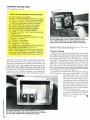
Preamplifier /Equalizer
Looking for an ultra- compact car stereo
preamplifier with seven -band equalizer,
and subwoofer crossover? Well, the PS -7
3 Remote Controls In One
With the universal remote control from
R.L. Drake, you would no longer have to
keep track of separate units for television,
videocassette recorder, and other audio/
video equipment.
The Model PRC/U allows the user to
operate up to three different remote -controlled components from one device. By
consolidating the functions of three remote-control units in one, this product
solves the problem of multiple modules.
In addition to being versatile, Drake's
universal remote control is extremely easy
to program. The user simply flips the
LEARN switch and places the Drake device
against the component's original remote
control unit so they're facing each other.
He then presses the function he wants to
program (such as on/off, change channel,
or fast forward) on the Drake unit and on
the original control. Every time that process is completed, Drake's control flashes
a light to indicate it has "learned" the
function. The user follows that procedure
for each function he wants the Drake remote control to perform. Drake's unit can
12
CIRCLE 67 ON FREE INFORMATION CARD
features front panel switchable tape and
CD inputs (high- and low-level tape inputs, continuously variable CD -input sensitivity), built -in front and rear fader with
outputs that can be full -range or a 12 -dB
per octave highpass filter at 150 Hz. The
subwoofer crossover has a continuously
variable crossover point (75 Hz to 150 Hz)
with a 24dB per octave slope.
The PS -7 is only one -in. high and features LED equalizer position indicators
which are also signal level indicators. The
model carries a $165.00 suggested retail
price.
For additional information contact Al-
phasonik, Inc., 701 Heinz Avenue,
Berkeley, CA 94710; Tel. 415/548 -4005.
capabilities; automatic channel calibration; 10 mV to 50 -Volt per division gain
scaling; user definable headings for spec trum/oscilloscope displays; save /retrieve
CIRCLE 68 ON FREE INFORMATION CARD
data to /from disk; menu driven, turnkey
software; and more.
The spectrum analyzer features: 250
KHz bandwidth; 1024 point FFT; X or X
& Y cursor; linear or log magnitude scaling; hanning or rectangular windowing;
spectrum averaging I to 64 spectra; variable or fixed scaling; and menu driven,
turnkey software.
Special features include display of multiple plots on a single screen for easy comparison; autoscaling of retrieved data to
display screen parameters; options can be
changed without leaving the real time display by use of the F keys; and color graphics displays.
With a suggested retail of $2995, the
system is available from Rapid Systems
Inc., 433 N. 34th Street, Seattle, WA
98013; Tel. 206/547 -8311.
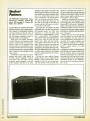
Car Amplifiers
High -end car audio installations are
more complicated and more expensive
than they have to be. But Denon's
DCA-3500 combines a front stereo amplifier,
a
rear stereo amp, a crossover, and a
subwoofer amplifier, in one compact
CIRCLE 69 ON FREE INFORMATION CARD
E
chassis in order to cut down installation
headaches and ultimately enable installer
to do more work in less time.
In five -channel operation, the
DCA-3500 is rated at 40 watts x 4 and 80
watts x 1, at !kHz and 1% THD. In three channel operation, power increases to 80
watts for the subwoofer. The built -in sub woofer dividing network offers a choice
of 80 Hz or 120 Hz crossover frequencies.
For added flexibility, switchable high -cut
and low -cut filters are also included. They
take effect at 12 dB and 18 dB /octave,
respectively.
Mounted in the trunk, the conventional
car audio amplifier can "see" a ground
potential different from that "seen" by
the head unit mounted in the dash. That
difference will be reproduced as noise. To
solve that problem, the Denon Real-World
Grounding system automatically senses
voltage differences between the signal
ground and the power ground. The amplifier applies an equal- but -opposite voltage
to cancel supply- induced noise.
The DCA-3500 also takes advantage of
two technologies originally developed for
Denon home amplifiers. First, Non Switching Class -A amplification eliminates crossover distortion from the output
transistors. Second, Denon's Non -NFB
circuit design corrects amplifier distortion
without resorting to negative feedback
a "solution" that sacrifices transient performance. The DCA-3500 also features
dual power supplies.
The new Denon DCA -3500 is thin
enough to mount out of the way. To make
sure heat dissipation is not a problem in
close quarters, the unit uses Denon's special Compact-Star heat sinks. The design
also uses efficient chimney -style heat
sinks with star-shaped radiating fins to
increase efficiency. Other features include
remote -power on /off, adjustable input
sensitivity, and gold -plated input jacks.
The amplifier carries a suggested retail
price of $470, and For more information
contact Denon America Inc., 27 Law Dr.,
Fairfield, NJ 07006; Tel. 201/575 -7810.
-
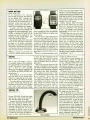
Jumbo LED Clock
If you've got poor eyesight, or just like
to say things in a big way, then this may be
your clock.
The Model 1036 Jumbo LED Clock has
CIRCLE 70 ON FREE INFORMATION CARD
12- or 24 -hour display capability with 6
2.25 -in. high, red LED digits. The battery
backed -up, quartz-crystal, time base automatically takes over during power failures
when the clock operates from a 60-Hz
power line. The clock will also operate
from 12 VDC. The high -tech black -plexiglas enclosure is attractive and functional, great for ham shack, computer
room, radio station, communications
center, home, office, and more. The dimensions are 15.25 x 4.75 x 1.5 inches
with a viewing distance of over 100 feet.
The model 1036 is available in kit form
with step by step instructions for $69.95
or assembled and tested for $99.95. For
green LED's (model 1036G) add $10.00.
For more information contact NRG
Electronics, PO Box 24138, Fort Lauderdale, FL 33307; Tel. 305/971 -3823.
Radio/Cassette Recorder /CD Player
They've finally created a stereo radio
cassette player with a built -in compact
disc player. And the player offers the FF-1
fine -focus, single -beam laser pickup.
Other features include 15 -step random access programmability, skip and search
LL EL
o WOC
WO
C
BOX 567
G.O.
-
VAN NUYS, CA 91408
BLACKLIGHT ASSEMBLY
Complete,
functioning
assembly
includes ballast,
-.,;,
,r =`__
.
<
on -off switch,
power cord, sockets and
F4T5 -BL blacklight. Mounted on a
7 1/8" X 3 1/8" metal plate.
Use for special effects lighting
or erasing EPROMS.
$10.00 EACH
CAT* BITA
1
mA METER
Modutec 0 -1 mA signal
strength meter with KLM
logo. 1/4" X 1 3/4" X 7/8" deep.
CAT* MET -2 $2.00 each
PUSHBUTTON PHONE
Spectra -phone Modell OP -1
1:1
1 piece telephone with
rotary (pulse) output.
Operates on most rotary or
touch tone systems. Features
last minute redial and mute
button. Includes coil cord
with standard modular plug.
7
IVORY.
CAT* PHN -1 $8.50 EACH
2 FOR $15.00
SWITCHING POWER SUPPLY
Compact, well regulated switching
power supply designed to power Texas
Instruments computer equipment.
INPUT:14 -25 vac @ 1 amp
OUTPUT: +12 vdc @ 350 ma.
+5 vdc @ 1.2 amp
.i
-5 vdc @ 200 ma.
SIZE: 4 3/4" square.
Includes 18 Vac @ 1 amp
wall transformer designed
.,_
to power this 00pplS,
CATI PS -TX $5.00 / SET
10 FOR $45.00
'
CIRCLE 71 ON FREE INFORMATION CARD
functions, a repeat key, and a comprehensive LCD display.
The cassette deck section (operated via
soft -touch controls) offers auto -reverse in
playback and record modes, a Dolby NR
system, and a reverse mode selector.
The selector allows the user to listen to
just one side playback, one side followed
by the other side, or repeated playback
alternating from one side to the other.
Cue and review controls, a pause control, and a soft-eject system are included
in the tape section as is a metal (play back)/CrO2- normal tape selector.
The RX -FD80 offers improved sound
dispersion from the two -way, four-speaker
system. The speakers at either end of the
unit each boast 51/2-in., PM woofers with
3/4-in. tweeters.
Ambience stereo-the feeling of having sound widely dispersed around the
room-is created when a portion of the
total sound is momentarily delayed and
cross -fed between the two speakers.
There is a balance control, and the
built -in graphic equalizer allows the individual to boost or attenuate the response
of five separate frequencies.
The RX -FD80 operates on IO D-batteries (not included). Jacks are provided
for: AC -in, headphones, line -in (2), line out (2), and mixing microphone.
The unit is currently available at a suggested retail price of $339.95. For more
(Continued on page /00)
A.
SLIM LINE FANS
TOYO* TF92115A New 115 Vac
-c
cooling fan. 3 5/8" square (ji /I`
X 1" deep. Metal housing.
1,
J'.
10.
5 blade impeller.
4
CAT* SCFE -115 $8.50 each
10 for $75.00
,
Ñ
+
VIC 20 MOTHERBOARD
26 ICs
including
6502A, 6560.
2
ea.
2
ea. 8128,
'
jili
It
6522,
/l'o
.
ué
.
r'
ea. 901486,
ea. 2114. Not guaranteed but great
for replacement or experimentation.
CAT * VIC -20
$15.00 each
2
3
ELECTRET CONDENSER MIKE
Mouser* 25LM044
Highly sensitive
mini microphone. 6" wire leads.
.39" dia.
X
.27" high. Omni
directional. Operates on 2 -10 Vdc
@ less than 1 mA. 1K impedance.
50 to 8 K Hz range.
CAT* MKE -1 $1.00 EACH
12VDC.
i
411
410i'µ
-
4PDT RELAY
Guardian* 1315P 5 amp contacts.
150 ohm coil. P.C. terminals.
Clear plastic dustcover.
CAT* 4PRLY -12PC $3.50 each
10 for $30.00
'WE'VE MOVED
OUR NEW ADDRESS IS
P.O. BOX 567 VAN NUYS, CA
=
800 -826 -5432
TOLL FREE ORDERS
600.826 -5432
(518) 904-0524
FAX - (818) 781 -2653
INFO
CIRCLE
5
NS-
91408
wó ;';á
;;,",
"i'17,O,qC 00.
.0111aGh MIX.
1.1.uos
,
sum...r
ON FREE INFORMATION CARD
13
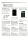
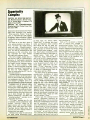
So you Bought a Shortwave Radio
By Gerry L. Dexter
How often is there help for the person
starting in a new hobby, especially a hobby like ham radio? If you need help, this
text may be of use. The book places special emphasis on making the reader aware
of the audio warp experienced by first time shortwave radio listeners, and helping the reader over that obstacle.
Rather than bombard the reader with
reams of information which he can't use
right away and may not care about any-
"
..
`Ti:-/^
How to
Design and Make
Your Own PCBs
.
`"'y'
-.t;-- :
SO YOU BOUGHT
,HOn""
51
copying PCB designs from magazines
and books and covers all aspects of simple
PCB construction as comprehensively as
possible. Chapter 2 covers photographic
methods of producing PCB's. Chapter 3
."C ).4e
,,,r:e!iw.e.ms}?
CIRCLE
ing DOS, saving and loading programs on
disk drives, playing around with sound,
`a
vE
94010!
ON FREE INFORMATION CARD
brief and basic, with
sources of more information provided for
each area discussed. The book shows the
reader where to tune for broadcast, aero,
marine, amateur, and other stations; presents lists of clubs, publications, and
in a light and easy,
shortwave dealers
non -technical style.
The book, which contains 74 pages,
retails for $6.95 from Tiare Publications,
PO Box 443, Lake Geneva, WI 53147;
Tel. 414/248 -4845.
way, the material is
-all
The One -Hour Commodore 64
By Tricia Jordan, Ph.D.
Studies slum that the first hour
person
deed. the first few minutes
spends with a computer sets the pace for
how that person reacts to and uses computers. Apple Computer certainly knew
that when it spent millions ensuring that
the first hour with a Macintosh would be
easy. friendly, and successful.
This book follows in that trend. Here's
what you'll find in it: setting up the computer, working with the keyboard, setting
up the cassette recorder, saving and loading programs on cassettes, setting up the
disk drive, a bibliography to help you find
more information. booting up and explor-
-a
-in-
CIRCLE 52 ON FREE INFORMATION CARD
using the printer for letters, programs,
and graphics, using the modem to connect
to the outside world, and a glossarydefinitions and fun with computer terms,
and special chapter on software-word
processing, financial management, data
base management, education, games,
graphics.
There are three working programs
drawing program to create pictures on the
screen and save them to cassette or disk; a
tutor program to create question and answer quizzes on any topic you with; and a
budget program to create expense reports
and reconcile your checkbook.
The softbound book contains 128 pages
and costs $5.95, from Info Books, PO
Box 1018, Santa Monica, CA 90406; Tel.
213/470-6786.
-a
How to Design and Make
Your Own PCB'S
By R.A. Penfold
A lot of electronics enthusiasts either
don't know how to make their own PCB's
or haven't gotten their technique straight
yet. Perhaps this book would be useful to
those of you in either category. The purpose of the book is to familiarize the reader with both simple and more sophisticated methods of producing printed
circuit boards.
The subject is not covered in a vague
and purely theoretical manner, as the emphasis of the book is very much on the
practical aspects of printed circuit board
design and construction.
Chapter I deals with simple methods of
CIRCLE 53 ON FREE INFORMATION CARD
deals with most aspects of designing your
own PCB layouts.
The book, containing 66 pages, costs
$5.75, and is available from Electronics
Technology Today, PO Box 240, Massapequa, NY 11762.
A Practical
Introduction
to Microprocessors
By R.A. Penfold
if you're a good electronics hobbyist,
but the microprocessor is still a mystery to
you, then this text may help clear things
up. The purpose of the book is to provide a
practical introduction to microprocessors
by constructing a very simple microprocessor circuit that the reader can actually build and experiment with and thus
hopefully gain a clearer insight into this
complex subject.
The completed unit is only intended as
an educational aid and is unlikely to be
usable in any actual applications, but it
can be built at quite modest cost and many
of the parts should be suitable for re-use
when the unit has served its purpose.
The book is not intended for complete
beginners at electronics. It is primarily
aimed at those who have some knowledge
of general electronics, but have little or no
understanding of microprocessors.
A Practical Introduction to Microprocessors costs $5.00, and contains 90
pages, from Electronics Technology To-
Practical
Introduction to
Microprocessors
A
CIRCLE 53 ON FREE INFORMATION CARD
day, PO Box 240, Massapequa. NY
11762.
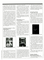
Building Metal Locators:
A Treasure Hunter's Project Book
By Charles D. Rakes
With these electronics projects, the fun
doesn't end after the construction is complete; it's only beginning! With the metal
detectors you'll build using this one -of-akind project guide, you'll be ready to get
started in a hobby that is exciting, challenging, and potentially profitable!
If you've ever dreamed of discovering a
buried treasure-stop dreaming and open
this guide of schematic diagrams, work in- progress drawings, and photos, complete part lists, step -by -step instructions -everything you'll need to build the
essential piece of equipment needed for a
BUILDING:
METAL LOCATORS
A TREASURE HUNTER'S
,
PROJECT BOOK
1
11,.,
1,
,.I.
your own backyard, or wherever hidden or
lost valuables might be found. Just some
of the various types of detectors covered
include frequency-shift metal locators
such as a simple beat frequency oscillator
(BPO), a BPD with selective filter detector, or a single oscillator high selective
filter locator circuit; balanced inductance
locators; transmitter /receiver circuits for
both small and large objects; and unusual
metal locator circuits.
You'll learn which types of components to use to achieve greater or lesser
sensitivity, what types of circuits to build
to locate objects at shallow or greater
depths, even how to develop a special locator geared to finding buried treasure.
Best of all, each one of the projects included are tested and proven original designs by the author, not just duplicates of
commercially -available kits.
The 114 page book retails for $9.95
from Tab Books Inc., Blue Ridge Summit, PA 17214; Tel. 717/794 -2191.
Assembly Language Subroutines
for MS-DOS Computers
By Leo J. Scanlon
Do you want over 100 useful subroutines to put extra programming power
at your fingertips? Let your fingers do
some walking through these pages.
This collection of practical, easy -to-use
subroutines is exactly what is needed for
performing high-precision math, converting code, manipulating strings and lists,
sorting data, displaying prompts and messages, reading user commands and responses, working with disks and files, and
doing countless other jobs. Models are
also included that provide the boilerplate
the assembler requires for use in the programs and subroutines that the reader develops.
The routines are for all MS -DOS computers -IBM PC JR XT, AT; Tandy 1000,
1200, 2000, 3000; TI Professional; Com-
ATTENTION!
Npás
çHN . .
E LEC
r
Our New and Highly Effective Advanced- Placement Program for experienced Electronic Technicians grants credit for previous Schooling and
Professional Experience. and can greatly reduce the time required to complete Program and
reach graduation. No residence schooling required for qualified Electronic Technicians.
Through this Special Program you can pull all of
the loose ends of your electronics background
together and earn your B.S.E.E. Degree. Upgrade your status and pay to the Engineering
Level. Advance Rapidly! Many finish in 12
months or less. Students and graduates in all 50
States and throughout the World. Established
Over 40 Years! Write for free Descriptive Literature.
COOK'S INSTITUTE
OF ELECTRONICS ENGINEERING
1EE
347 RAYMOND ROAD
P.O. BOX 20345
JACKSON. MISSISSIPPI 39209
CIRCLE 7 ON FREE INFORMATION CARD
AMAZING
SCIENTIFIC & ELECTRONIC
PRODUCTS
PLANS-Bum Yoursett -AN Parts Available In
LC7- BURNING
TCC1
-3 SEPARATE TESLA COIL
PLANS T01
5
Stock
CUTTING CO, LASER
RUB4- PORTABLE LASER RAY PISTOL
_..
.
20 00
10.00
MEV
-ION RAY GUN
GRA1- GRAVITY GENERATOR
IOG1
EMl1- ELECTRO MAGNET
s 20.00
20.00
TOM
6.00
COIL GUN/LAUNCHER
KITS
MFT
1
K
-FM VOICE
TRANSMITTER 3 MI RANGE
VWPMSK- TELEPHONE TRANSMITTER 3 MI RANGE
BTC3K- 250,00 VOLT 10.14" SPARK TESLA COIL ..
LHC2K- SIMULATED MULTICOLOR LASER....
BLS1K- 100,000 WATT BLASTER DEFENSE DEVICE
ASSEMBLY
CIRCLE 54 ON FREE INFORMATION CARD
LANGUAGE
SUBROUTINES EOR
-a
metal detecsuccessful treasure hunt
tor. An exciting, low-cost alternative to
expensive commercially-made metal locators, the detectors included in this
unique project guide will locate anything
from coins and jewelry to gold and silver,
and can be built quickly and easily by any
electronics enthusiast!
With Charles Rakes' guidance in designing and building metal detectors,
you'll be ready to hit the beach, old abandoned home sites, old carnival sites, recreational parks, playgrounds, racetracks,
MS -DOS
COMPUTERS
ITM1K- 100.000
MIN
CIRCLE 54 ON FREE INFORMATION CARD
69 50
RANGE INTIMIDATOR
PSP4K -TIME VARIANT SHOCK WAVE PISTOL
PTG1K- SPECTACULAR PLASMA
5950
149 50
TORNADO GENERATOR
MVPIK SEE IN DARK KIT
...
ing assembly language code, this outstanding reference gives the computer
169 50
ASSEMBLED
PG70H- MULTICOLORED VARIABLE
9TC10-50.000 VOLT-WORLD
425 00
S
SMALLEST
450
TESLA COIL
LGU46-1MW HeNe VISIBLE RED LASER GUN
TAT20 AUTO TELEPHONE RECORDING DEVICE
GPVIO -SEE IN TOTAL DARKNESS IR VIEWER
LIST 10-SNOOPER PHONE INFINITY TRANSMITTER
299.50
24.50
299.50
169.50
IPG70-INVISIBLE PAIN FIELD GENERATOR-
74.50
MUL TI MODE
paq: and any IBM-compatible computer.
Saving the programmer from having to
constantly reinvent the wheel when creat-
3950
69.50
VOLT 20' AFFECTIVE
MODE PLASMA GLOBE .7
uo I. xANroN
49.50
39.50
199.50
CATALOG CONTAINING DESCRIPTIONS OF ABOVE PLUS
HUNDREDS MORE AVAILABLE FOR ST ODOR INCLUDED FREE
WITH ALL ABOVE ORDERS.
PLEASE INCLUDE $3 00 PH ON ALL KITS AND PRODUCTS
PLANS ARE POSTAGE PAID SEND CHECK. MO. VISA. MC IN
Us FUNDS
INFORMATION UNLIMITED
P.O. BOX
716 DEPT. H O
AMHERST, NH 03031
15
user instant access to over 100 commonly
needed routines. Never again will programmers be forced to waste valuable
time wading through manuals or tutorials
in search of a routine that reads a name
from the keyboard, displays a message on
the screen, or does some other common
task.
To making it much more than just a
subroutine sourcebook, the author gives
real -world interaction with the software
tools that assembly language programmers use. Step -by-step procedures are
demonstrated for using the IBM and Microsoft Macro Assemblers, as well as the
full details on the EDLIN line editor,
SYMDEB and DEBUG debuggers. and
the
of course, to play games.
It contains lots of ways to save time and
money -even ways to use it to make
money -it's a book that'll inspire the
reader to come up with still more ideas.
The authors have provided all -new,
commercial -quality programs for financial business and educational applicaand
tions, unique games, a library of
computer specific utilities and subroutines, sound and graphics, printouts,
flowcharts, diagrams, and a wealth of illustrations.
Containing 208 pages, the book retails
for $12.60, from Tab Books Inc., PO Box
40, Blue Ridge Summit, PA 17241; Tel.
717/794 -2191.
LINK and EXE2BIN utilities. Also
included is a summary of the entire 8086,
8088, and 80286 microprocessor instruction sets, arranged in logical groups for
quick learning and easy reference.
Assembly Language Subroutines for
MS-DOS Computers contains 350 pages,
costing $19.60 in paperback and $27.95
as a hardbound, from Tab Books Inc., PO
Box 40, Blue Ridge Summit, PA 17214;
Tel. 717/794 -2191.
Things to Do with Your Amiga
By Mark Sawusch and
Dave Prochnow
How about a book that puts the full
applications potential of the Amiga within the reach of every one of its users? This
book is a collection of more than 1000
ways for Amiga owners to take advantage
of the unique features of one of today's
most-sophisticated micros for uses ranging from household record- keeping and
budgeting. to investment analysis and
1001
Supercharging Your PC
By Lewis Perdue
We all know the PC has a wide variety
is right
for you? This book tries to make the list of
of expansion options, but which
memory boards, RAM disks, print
spoolers, hard disks, hardcards, bubble
memory, graphics boards and monitors.
modems, networks, electronic mail.
mice, light pens, bar code readers, voice
input, digitizers, scanners; optical disks,
PC -Fax boards 80386 accelerator boards,
AT emulation, and more.
Every chapter presents a hardware or
software solution to an expansion prob-
1001
AMIGA
business management; from game playing and hobby use, to scientific and edu-
cational utilization.
Best of all, the guide reveals numerous
techniques for using the Amiga in a huge
variety of practical and just - for-fun ways:
to forecast weather; to help youngsters
make better grades; to calculate camera
settings; to keep a business on the road to
better profits; for technical applications;
The One -Hour Atari XL
By Tricia Jordan, Ph.D.
Info Books has designed its "One -Hour
Books" to lead readers, page-by-page,
from one easy. friendly, and successful
experience with their computers to another. This book is an example of that user
friendly technique.
Here's what you'll find in this compact,
easy-to-read book: setting up the computer, working with the keyboard, setting up
the cassette recorder, saving and loading
programs on cassettes, setting up the disk
drive, a bibliography to help find more
information, booting and exploring DOS,
choices clear.
Supercharging your PC is easy with
this do -it- yourself expansion guide for
your IBM or compatible PC. Perdue
shows you tricks you can use to get your
PC performing at top speed. You can add
THINGS TO DO WITH YOUR
CIRCLE 54 ON FREE INFORMATION CARD
Best of all. Supercharging Your PC has
do- it- yourself format -you'll save
money while you become a PC expert.
Retailing for $19.95, the book contains
358 pages and is available from Osborne/
McGraw -Hill, 260010th Street, Berkeley,
CA 94710; Tel. 415/548 -2805.
a
CIRCLE 55 ON FREE INFORMATION CARD
lem. You learn how to select and use utility software and hardware enhancements
and implement other hardware enhancements and implement other techniques to
gain greater RAM, more disk storage, and
better graphics. You'll also find out how
to choose a PC clone for maximum reliability and compatibility; and make
powerful applications programs like
Lotus -2-3 and dBASE run faster and
1
more effectively.
CIRCLE 52 ON FREE INFORMATION CARD
saving and loading programs on disk drives, playing around with sound, using the
printer for letters, programs, and graphics, using the modem to connect to the
outside world, using the modem to connect to the outside world, and a glossary.
Also special chapters on software,
word processing, financial management,
data base management, education,
games. and graphics.
The working programs contained in the
text include: drawing programs to create
pictures on the screen and save to cassette
or disk; a tutor program to create question
and answer quizzes on any topic you
wish; and a budget program to create expense reports and reconcile your checkbook.
The 120-page softbound edition costs
$5.95 from Info Books, PO Box 1018.
Santa Monica, CA 90406.
Computer Integrated
Manufacturing Handbook
By Eric Teicholz and Joel N. Orr
If you're into letting machines do all the
work, then this is for you.
A highly practical treatment of the increasingly important technology of CIM,
the book presents vital information for
understanding and implementing issues
in easy -to- understand terms (McGraw Hill, $59.95).
Under the direction of Editors Eric
Teicholz and Joel N. Orr, more than 20
specialists in the field have contributed
significant material on their areas of expertise. They tell exactly what must be
done to convert today's workplace into the
factory of the future, emphasizing the
economics and the specifics of CIM.
The Computer -Integrated Manufacturing Handbook shows how to utilize CIM
technology by exploring the technologies
and methodologies involved, by describing the obstacles to be overcome when
CIM programs are started in typical industrial situations, and by examining the implementation issues to be considered.
This authoritative resource investigates
a wide range of important aspects, from
the role of CAD/CAM in CIM to numerical control systems, from a concise overview of the CIM industry to a projection
of future trends and developments. Full
discussions deal with such topics as group
technology, robotics, process planning,
CIRCLE 57 ON FREE INFORMATION CARD
production planning and control, the role
of materials handling, technology management and factory automation, planning for a competitive CIM environment,
and the considerations of controls, feedback, and benchmarking for successful
implementation.
The Computer Integrated Manufacturing Handbook, contains 466 pages; and
costs $59.95; from McGraw -Hill, 1221
Avenue of the Americas, New York, NY
10020.
ELECTRONIC
COMPONENTS
integrated circuit technology -such as
TTL IC's to CMOS
CATALOG
the shift away from
and ECL devices.
Filled with stimulating ideas on and
practical solutions to problems in electronic instrumentation design, the guide
examines the entire process from input/
sensor to output/display. It includes both
.
.
.
yours FREE
by dialing
1- 800 -992 -9943
In
Texas: 817/ 483 -4422
Call Today for your FREE
subscription to the 1987
Mouser Electronics Catalog.
Contains 176 pages featuring
over 16,000 in- stock, quality
electronic components.
..PLUS..Mouser's proven
service and prompt delivery.
Circuit Design
for Electronic
Instrumentation
rnv!
DAROLDV`IbBSCHALL
(Outside U.S.A., Send $2.)
MOUSER
CIRCLE 55 ON FREE INFORMATION CARD
ELECTRONICS
analog and digital circuits, and emphasizes interfacing and the interrelation of
circuits.
With 80 percent of the material in the
second edition either new or thoroughly
revised, the book offers greatly expanded
sections on sensors and communications.
The author has also updated the circuits to
employ newer and better devices, providing sufficient design information to allow
for the construction of simpler circuits.
Subtitled Analog and Digital Devices
From Sensor to Display, this reference
has full coverage of everything from semiconductor devices and basic circuits, to
signal amplification and processing; from
data switching, control and readout. to
power circuits. It explains in detail such
diverse topics as temperature sensors,
electro- optical devices, displacement
sensors, chemical and biological electrodes, oscillators and signal sources,
analog -to- digital conversion, noise and
noise reduction, multiplexing, digital
data communication, and power amplification and control circuits. In his discussions, the author avoids extended
mathematical treatment except where it is
needed for full comprehension.
Circuit Design for Electronic Instrumentation: Analog and Digital Devices
From Sensor to Display, contains 377
pages at a retail price of $49.50, from
McGraw-Hill, 2600 Tenth St., Berkeley
CA, 94710; Tel. 415/548-2805.
2401 Hwy 287 North
Mansfield, Texas 76063
c
DISTRIBUTION
CENTERS
NATIONWIDE
CIRCLE
11
ON FREE INFORMATION CARD
Circuit Design for Electronic
Instrumentation-2nd Edition
By Darold Wobschall
Sure you can build projects. but how
about instruments? This book presents vital information on the standard devices
and techniques for the electronic design
process, and has been extensively revised
and updated to reflect the latest changes in
Advanced Graphics in C
By Nelson Johnson
Add graphics to your C programs, and
you'll add significant capabilities to your
software. With Advanced Graphics in C
you'll be able to write graphics programs
for the IBM EGA (Enhanced Graphics
CIRCLE 13 ON FREE INFORMATION CARD
1
7
Adaptor) -the de facto standard for high -
with Turbo Pascal; a library of useful programs for personal and business uses.
There are, for example, database programs, a financial projection program, a
quality graphics programming on the
IBM PC.
Advanced Graphics in C offers a special graphics program, called GRAPHIQ,
that provides a complete toolkit of all the
routines you'll need for graphics operations. Johnson shows you how to use
GRAPHIQ to implement or adapt graphics in your C programs.
It also provides: A special appendix
that includes the code for GRAPHIQ, a
complete graphics program with a rotatable and scalable character set. It's full of
CIRCLE 52 ON FREE INFORMATION CARD
tually work. The book covers everything
from calculating a percentage to determining the true cost of an adjustable -rate
mortgage. In addition, you'll learn about
the tricks professionals use to take advan-
Graphics in C
of unwary investors and borrowers.
And you'll see the long-term effect taxes
and inflation have on your personal
wealth -and what you can do about it.
Each chapter has real -life exercises so you
can see how the formulas work.
The soft -bound book contains 172
pages and costs $9.95, from Info Books,
PO Box 1018, Santa Monica, CA 90406:
Tel. 213/470-6786.
tage
CIRCLE 55 ON FREE INFORMATION CARD
tools not available elsewhere. An entire
stroke /front character set; code for the
AT &T Image Capture Board; information
on serial and parallel interfacing to mice,
light pens, and digitizers.
With this text you'll learn state-of-theart techniques from Johnson so that you
can easily create the graphics you need.
The book contains 660 pages and re-
tails for $22.95 from Osborne /McGrawHill, 2600 10th Street, Berkeley, CA
94701; Tel. 415/548 -2805.
Your Best Interest: A Money
Book for the Computer Age
By Tom Weishaar
We are peasants in the Dark Ages of
money. Compound interest confounds us.
Interest rate magicians pick our pockets
daily. monthly, and quarterly. But just as
the printing press liberated us from
feudalism and superstition, the personal
computer can now free us from the decep-
Turbo Pascal For Basic
Programmers
By Paul Garrison
Most computer programmers begin by
learning BASIC. But as computer languages go, BASIC is slow and cumbersome. Now, with Borland's affordable
Turbo Pascal software, individuals and
small business owners are seizing the opportunity to step up to a high -level, structured language for faster, more efficient
programming.
In this book, Paul Garrison draws from
your knowledge of BASIC programming
fundamentals to show you how Turbo Pascal works. BASIC programs are compared-side by side-with their Pascal
equivalents so that you can see clearly the
-
Advanced C: Techniques
and Applications
By Gerald E. Sobelman
and David E. Krekelberg
It you have basic knowledge of the C
programming language and are ready for
more, then you should have Advanced C:
Techniques and Applications.
By the time you finish Advanced C, you
will have constructed several state- of-the-
CIRCLE 58 ON FREE INFORMATION CARD
art applications. Learn how to: generate
and control advanced graphics, develop a
tion of financial warlocks.
Until now. there have been books about
money, and books about computers, and
books for owners of one spreadsheet for
one particular computer. Your Best Interest is a book that explains financial
spreadsheet calculations in a generic fashion. The information can be used with any
spreadsheet, on any personal computer.
Weishaar is an expert at making complex ideas simple. He shows you how to
get any common spreadsheet program to
do the mundane, time -consuming, and
error-prone arithmetic of interest rates
instantly and automatically.
But more than that, you gain an understanding of how financial transactions ac-
currency conversion program, a mortgage
amortization program, and many more;
seven appendixes that include the ASCII
character codes, a Turbo Pascal dictionary, a glossary of computer terms and abbreviations, and other helpful aids.
If you want more information about
Turbo Pascal procedures and functions;
loops and arrays; pointers, heaps and
stacks, Turbo Pascal for BASIC Programmers is for you.
A hands -on tutorial, this book shows
you how to use Turbo Pascal to turn your
computer system into a powerful developmental tool.
The book is 406 pages, and retails for
$16.95, from Que Corporation, 7999
Knue Road, Suite 202, Indianapolis, IN
46250; Tel. 317/842 -7162.
CIRCLE 58 ON FREE INFORMATION CARD
similarities and differences of the two languages. The comparisons demonstrate
why Pascal is easier to write, easier to
read, and easier to test and debug.
Look inside this book and find: clear
and easy-to- understand explanations of
the specifics of structured programming
menu -driven, multiwindow environment,
and construct advanced user interfaces.
Advanced C is one of the few books
available that focuses on the advanced features and capabilities of the C programming language. Important topics in this
book include C coding style pointers, recursion structures, linked lists, and trees.
The book can give you a deeper understanding of the C language and help you
develop techniques that will enhance your
programming skills.
The book, containing 316 pages, retails
for $21.95 from Que Corporation, 7999
Knue Road, Suite 202, Indianapolis, IN
46250; Tel. 317/842 -7162.
can even earn your Associate in
Applied Science Degree in Electronics Engineering Technology. Of
course, you set your own pace, and,
if you ever have questions or
problems, our instructors are only
a toll-free
phone call away.
ie first step
is yours.
To find out more, mail in the
coupon below. Or, if you prefer,
call toll -free 1-800-321-2155
(in Ohio, 1-800-523-9109).
We'll send you a copy of CIE's
school catalog and a complete
package of enrollment information.
For your convenience, we'll try to
have a representative contact you
CIE MAKES THE WORLD
OF ELECTRONICS YOURS.
Today's world is the world of electronics. But to be a part of it, you
4K RAM Microprocessor Training
Laboratory, for example, trains you to
work with a broad range of computers in a way that working with a
single, stock computer simply can't.
need the right kind of training, the
kind you get from CIE, the kind that
can take you to a fast growing career
in business, medicine, science,
government, aerospace,
communications, and more.
trsonalized
raining.
SPcialized
You learn best with flexible
taining.
training, so we let you choose from
a broad range of courses. You start
with what you know, a little or a
lot, and you go wherever you want,
as far as you want. With CIE, you
You learn best from a specialist,
and that's CIE. We're the leader
in teaching electronics through
independent study, we teach only
electronics and we've been doing
it for over 50 years. You can put
that experience to work for you
just like more than 25,000 CIE
students are currently doing
all around the world.
AHO-67
CIECleveland
1776 East 17th St.,
Institute of Electronics
Cleveland, Ohio 44114
YES! I want to get started. Send me my CIE school catalog including details about
the Associate Degree Program. I am most interested in:
television /high fidelity service
computer repair
medical electronics
telecommunications
broadcast engineering
robotics /automation
other
actical
training.
Print Name
You learn best with practical training,
so CIE's Auto -Programmed® lessons
are designed to take you step -by-step,
principle-by- principle. You also get
valuable hands-on experience at every
stage with sophisticated electronics
tools CIE-designed for teaching. Our
to answer your questions.
Apt
Address
City
I
state
Age
Area Code/Phone No.
Check box for G.I. Bulletin on Educational Benefits
Veteran
Active Duty
CIRCLE
Zip
6 ON
MAIL TODAY!
FREE INFORMATION CARD
21
By Herb Friedman
v
I
Lit,\1
Now
OAS
ON C OMPUTERS
to stretch your budget for hard -disk storage.
PROGRAMS CONTINUE GETTING
larger and more complex, the standard,
two -floppy configuration of IBM -compatible computers is hard -pressed to
provide the necessary storage. Soon, the
average user starts to think in terms of the
megabyte storage capacity of a hard -disk
system. Although the past year has seen
the price of a hard -disk unit drop like a
lump of lead, even the most -minimal
hard -disk system comes out to several
hundred dollars.
But there's a lot of inexpensive hard disk hardware floating around the surplus and mail -order dealers, not to overlook
the flea markets. Even without a calculator, it's easy enough to figure out that
a hard -disk system won't cost much
beyond $225 if you do it yourself. Unfortunately, doing it yourself can turn out to
be prohibitively expensive if you don't
know what you're doing, and very few
least in our experience
dealers
give you much assistance. In fact, some
won't give any assistance -What you
order is what you get!
-at
V
priced from $85 to about $100. The controller usually comes with a set of two
cables that connect the controller to the
drive. Depending on the particular dealer,
you might have to do some fast talking to
get the cables thrown in; but if he won't do
it, try a different dealer or make the cables
yourself-the connectors are standard.
While there are other kinds of controllers
in the marketplace, some of which -such
as the RLL type-claim to provide greater
disk storage capacity compared to the the
Western Digital controller, if you want to
have the system work the first time, or
with a minimum number of headaches,
stick with the WX -/ and WX -2 controllers.
Enough Power
It you have one of the older computers
with a 60-watt power supply and full -size
-will
Why They're Cheap
First things first; why are some hard disk drives so cheap? It's because the
business market, for whom they're intended, want capacities exceeding 30
megabytes. Warehouses are overflowing
with 10- and 20- megabyte hard-disk drives that the business community no longer
wants, and so they're unloaded at bargain basement prices -particularly the 10megabyte models. But 10 or 20 megabytes is plenty of storage for most small
users; so if you're willing to settle for less,
you can upgrade to a hard -disk system for
less than the original wholesale cost of the
drive. In fact, if you can settle for 10megabytes of storage, you can pick up the
Microscience model 6/2 drive shown in
the photographs -one of the best because
it has a plated media and automatic head
parking-for a little more than $100.
Actually, a basic hard -disk system consists of only the parts shown in the photos:
a hard -disk drive mechanism and its controller. The controller, which is usually
the half-slot size Western Digital WX -/
(see photos)-or its almost functionally identical full -size twin, the WX -2
-is
22
disk system consists of a controller and a hard disk drive. This pair
cost less than S100. But notice the drive came without a front panel.
A hard
This half -size "WX -1" hard -disk controller has two smaller header terminal
strips, which can each drive a disk drive. The larger header strip is split
by a Y- adapter or a two -connector cable when using two disk drives.
-
drives, you'll probably have to remove the "B" drive, so that
you'll have mounting space and power for the hard -disk drive
whether it's a half- or full -size drive. If you have one of the newer
computers, it probably has half-size drives and a power supply of
at least 120 watts that has two sets of extra power connectors (a
total of four). You can fit either a half- or a full -size, hard -disk
drive into the empty panel space and then simply plug it in to the
power supply.
Now it's conceivable that your el cheapo hard -disk unit will
arrive without a front panel. (Surprise! That wasn't even implied
in the advertisement.) No problem. Simply make your own from
one of the plastic filler panels that cover the disk drive openings
in the front of the cabinet
press the filler forward and out
or cut a piece of plastic to fit. The panel doesn't have to attach to
the drive because the drive is really held in place by two to four
screws, not by the front panel. The panel contains only two
LED's, which indicate that power is on (red) and that the disk is
in use (green or yellow). The connector for the LED's are three
pins near the front of the drive.
Simply install two LED's on a plastic filler panel (see photos).
Tie one lead from each into a common connection -which is
usually negative-and pre-wire the three leads to a connector
that matches the three pins on the disk drive.
just
-
"TAKE ONE"
Take one look at the new MCM
catalog and you'll discover...
An unbeatable line -up
of parts and products
Many new items that
are hard to find
Great values that save
you money
your hard disk drive came without a front panel, you can make
your own by simply installing two LED's on one of the plastic filler
panels: or cut a front panel from a piece of plastic. Use a small
wire tie -indicated by the pointer -to keep the wires together.
If
You'll also discover convenient ordering with
our TOLL -FREE lines, fast and friendly service,
plus quick shipment on the items you need.
-
Setting the DIP's
The drive comes with a data sheet that tells how to set the
internal DIP switches for one or two drives. If you didn't get the
data sheet, get on the phone and insist that they send the data or
give you the information over the phone. Set the DIP switches
accordingly, and install the drive in the computer.
Attach the LED connector, and then seat or tape the front
panel onto the cabinet. Install the two connecting ribbon cables
between the controller and the disk drive. The color-coded wire
on one side of each cable is pin I for that cable.
Next, program the controller for the disk drive. Programming
is done by simply moving a few jumper blocks to the appropriate
pin connections, as the photos show. (For clarity, we have temporarily removed the cables.) How do you know what goes
where? The controller should have been supplied with a small
paper guide that shows which block goes where depending on
factors, such as whether the drive is 10- or 20- megabytes, the
sector arrangement, etc.
(Continued on page 100)
--
All of this is in the new MCM catalog
and we
invite you to "Take One." For your copy
with
no obligation to buy
call TODAY!
TOLL -FREE
1. 800 -543 -4330
In Ohio, 1. 800 -762 -4315
Alaska and Hawaii,
1. 800. 858.1849
In
RYA
'
"4
i%
MCM ELECTRONICS
858
E. CONGRESS PARK DR.
CENTERVILLE, OH 45459
A PREMIER Compa' v
SOURCE NO. HO -07
CIRCLE 12 ON FREE INFORMATION CARD
23
Pride, quality,
When you unpackage a Heathkit product, you open up a special world, a world
providing a unique blend of achievement and fun. With your Heathkit product, you'll enjoy the pride of building it yourself, and the confidence that it's built
right. Along with the convenience and assurance of knowing how to keep it
running at peak performance. Plus you'll learn about new and emerging
technologies. For knowledge that gives you that added edge in your field. But
most important, with a Heathkit product you're buying from a company whose
name is synonymous with quality and enjoyment. From our easy -to-follow
documentation to our renowned technical support, we make sure your
kitbuilding experience is fun and relaxing - as well as rewarding.
And when you're done, your pride will be matched by the
satisfaction of owning a product that you know inside out.
And that will last a long time. Thousands of people
have discovered this unique dimension in
product ownership. We'd like you
to discover it, too.
For information on all our quality kits,
send NOW for your FREE four-color
Heathldt Catalog.
Send to: Heath Company, Dept. 107 -584
Benton Harbor, Michigan 49022
GR -9009 9" AC/DC
Color TV - ONLY $249.95
-----+`
11111
fun... Heathkit
Enter the Heathkit world with ...
The Heathkit ID -4001
Weather Computer, which puts
weather information at your fingertips. With the
press of a button, you can instantly know temperature, wind speed and direction, and barometric
pressure for the exact location in which you live. For
planning outdoor activities with greater assurance
than ever.
And its all done with unsurpassed accuracy.
Long life IR LED's act as sensors to make both the
wind speed cups and the wind direction vane as sensitive and as accurate as a costly laboratory instrument. While active solid state devices reliably
measure indoor and outdoor temperatures, all stored
by a microprocessor for later recall.
Attractively designed, the ID -4001 will give you
extraordinary performance unheard of at such a
reasonable price,
$399.95.
The IC -1001 Logic
Analyzer is the perfect answer for trans-
form i ng a PC-compatible computer or standard
terminal into a versatile logic analyzer.
A top -grade troubleshooter and design aid, the
compact Logic Analyzer includes 16 data lines plus
clock and two qualifier lines, checksum capability,
and state and timing displays with hex, octal and
ASCII equivalents. You can even use it in circuits
with clock speeds up to 10 MHz, trigger on any digital
word and view events 2,000 pulses before trigger and
up to 50,000 pulses after. High impedance inputs
virtually eliminate circuit loading.
And it's easy to use! The highly intuitive user friendly software makes the IC -1001 fully keyboard configurable and menu -driven. All in one portable unit.
Put this most advanced technology to work for
you - for only
$269.00.
call toll -free 1- 800 - 253 -0570.
Ask for Operator 410.
To order,
We also have 66 Heath /Zenith Computers &
Electronics stores in North America.
Call 616- 982 -3614 for the store location nearest you.
- ..F4áAlo.wçfgrsPr':FroI
Prices. product availability and specifications are subject to change without notice.
CIRCLE 9 ON FREE INFORMATION CARD
Heathkit®
Company
KB-103
1
By Don Jensen
ON DXING
I
Do you know what country is it?
"l'S
FLAG IS RED, WHITE, AND BLUE. ITS
currency is the US dollar. It was the first
independent republic on its continent. and
it is governed by a President. Senate. and
House of Representatives. Its national
capital is named after a famous American
president.
Sure, it's a trick question. The country-and our DX'ing target this month
is the west African nation of Liberia. That
many
Liberia's government is
ways -patterned after the United States is
no accident. It was tounded by an organization called the American Colonization
Society in 1822 as a haven for freed slaves.
Unfortunately. Liberia never lived up to
the dreams of its idealistic founders. It is
today just another poor and undeveloped
Third World country. steaming away in
one of the hottest and most humid corners
-
-in
of Africa.
America. though, is still offering assistance to the tiny African country, which
was once its ward. One way is the USAIDsponsored Liberian Rural Communications Network. which set up a series of
broadcasting stations last year to bring
local radio to the least developed parts of
the country.
Those local stations
places with
names like Voinjama, Zwedru. and
-in
Gbarnga -are low- powered. medium wave outlets. normally not audible much
bey( nd their 75 -mile primary range. But
they are served by a LRCN shortwave
link. which can he received by SWL's in
North America.
There are three other shortwave services in Liberia for the shortwave listener
to track down and log. One is the easy-tohear. but not- very -exciting, Voice of
America (VOA) relay station at the Liberian capital of Monrovia.
Tougher and. therefore. more challenging DX targets are two other shortwave
services, the commercial Liberian Broadcasting System and the cultural and religious broadcasting service of the Sudan
Interior Mission, Radio ELWA.
LRCN is the newest of the lot and the
most recent to come to the attention of
North American SWL's. It operates a IOkilowatt independent sideband transmitter
on 3.975 kHz, where. unfortunately, it
often suffers interference from the British
26
Broadcasting Corporation's ( B BC ) mare
powerful signals.
According to William E. Mackie, who
heads the USAID technical advisory team
in Monrovia, the SW outlet is used to feed
the national newscast to its remote microwave stations in the bush. The very
brief
ABBREVIATIONS
BBC
British Broadcasting
Corporation
CST
UTC 6 hours
long distance (over 1000
miles)
listening to shortwave
DX
DX'ing
shortwave schedule runs twice daily,
Monday through Saturday, at 0700 UTC
(when it can be heard in North American)
and at 1900 UTC (when it cannot). Mondays through Fridays, the news is followed
at 0715 UTC by a half-hour information
program called "Network Liberia." Programming is all in English.
VOA has one of its worldwide network
of shortwave relay operations in Liberia
and beams programs to Africa from a series of six huge 250.000 -watt transmitters
and two older 50- kilowatt units.
Programming is standard VOA fare.
hardly distinguishable from other Voice
operations except for the occasional indentification.
You can find the VOA's Liberian relay
at various times, such as between about
1600 and 2200 UTC. Some frequencies to
try include 15,445, 15,600, 17,870 and
21,485 kHz.
Radio ELWA is a religious broadcaster
that has been operating from Monrovia for
years on shortwave. It is a rather substantial broadcaster, with a pair of 50- kilowatt
and two 10 -kW shortwave transmitters.
ELWA programs in English, French,
Arabic, and several west African languages, such as Hausa, Ibo, and Fulfulde.
Look for this one in English from 0600
UTC on 4,760 kHz. It is also scheduled
from 0700 UTC on 11,830 kHz and from
0825 UTC on 6,070 kHz.
ELBC, the Liberian Broadcasting System, also in the capital of Monrovia, offers something a bit different to the SWL's
ear-West African commercial radio.
It has a 50- kilowatt shortwave transmitter and can be best heard on 3,255 kHz,
beginning at 0530 UTC. With some
effort, good reception conditions, and a
bit of luck, SW listeners in many parts of
North America may manage to log all four
of the Liberian shortwave outlets.
questions is where should I tune to find a
particular station and when? And one of
the best answers to that question, in my
view, is the annual Radio Database International volume, which is really a "Passport to World -Band Radio."
The third edition of the book is just out,
some 400 pages of information. A big part
of the RDI publication is its computergenerated graphic presentation of the
shortwave frequencies- showing stations, frequencies, and daily schedules
based on actual worldwide monitoring.
The graphic data also tells you the major
languages being aired and when, the station's power, and much more.
In addition, you will find RDI's expert
reviews of shortwave receivers, accessories and antennas. plus feature articles.
Radio Database International's new
book is available from many shortwaveradio dealers around the world for $14.95.
or from the publisher-RDI, Box 300,
an additional
Penn's Park, PA 18943
$1.95 shipping and handling charge.
Book Look
One of the most commonly asked SWL
Weather Over There
J. N.M. Legate, a reader in Glovertown,
broadcasts
5 hours
frequency modulation
FM
(modulated)
kHz
kiloHertz (1000 Hertzs or
cycles)
kw
kilowatt (1000 watts)
LRCN
Liberian Rural
Communications Network
MST
UTC + 7 hours
PST
UTC + 8 hours
RAF
Royal Air Force
RDI
Radio Database
International
SW
shortwave
SWL('s)
shortwave listener(s)
TV
television
UTC GMT Universal Time Code
Greenwich Mean Time
VOA
Voice of America
VHF
very-high frequency
EST
UTC
-
-for
Newfoundland, Canada, says that SWL's
planning a trip to Europe might be interested in the sort of weather they can expect
before they depart. If a "listener" has a
receiver that can tune in sideband signals,
he says, Shannon Airmet is received quite
well in Newfoundland, and may be heard
in the USA too.
The aeronautical transmissions from
Ireland's big international airport offer
regular weather reports. Reception is variable, but not often inaudible with 5,640
and 8,957 kHz being the best during
daylight hours and 3,413 kHz, at night.
Sometimes, he adds, 13,264 kHz is
good for daytime reception. The weather
is given for numerous international airports all over Europe, from Athens to
Shannon. Reader Legate also says that the
British Royal Air Force Volmet station
gives weather for RAF bases, plus the
major United Kingdom civilian airports
such as London's Gatwich and Heathrow,
plus Prestwick and Manchester. Reception is usually good on 11,200 kHz
daytimes and on 4,722 kHz at night.
Down the Dial
In answer to some recent questions
about this monthly feature, the times
listed are in Coordinated Universal Time,
abbreviated as UTC, which more veteran
SWL's may know as Greenwich Mean
Time or GMT.
UTC /GMT is a generally recognized
time standard in international broadcasting. To convert to your local time, sub tract 5 hours for EST, 6 hours for CST, 7
hours for MST or 8 hours for PST. SWL's
also use 24 -hour clock time, in which
0100 signifies I AM UTC; 1300 is I PM
UTC; 2100 is 9 PM UTC, and so on.
Frequencies in the following reports are
in kilohertz (kHz), and are stations that
other readers (like yourself) are hearing.
Your SW loggings can appear in this section too if you'll just drop me a note with
your information to Jensen On DX'ing,
Hands -on Electronics, 500 -B Bi -County
Blvd., Farmingdale, NY 11735.
Belguim-15,590, Belgian Radio and
You Can Be
TV has its English shortwave service, including news and features, at 1330 hours.
One Of The
Czechoslovakia -5,930, Radio
Prague is an eastern European broadcaster widely heard in North America. Its
Sunday Magazine program in English has
been logged here at 0100, and also at
0300. Try also 7,345 and 11,990 kHz.
French Guiana -3,385,
FR3 is the
SW voice of this colonial French outpost
in South America, which has been noted
at about 0930 hours
with
a
program
schedule, a rooster's crowing and then
popular music.
Falkland Islands- 3,958, from the
South Atlantic comes the programming of
the British Forces Broadcasting Service,
aired by the Falkland Islands Broadcasting Station. Try this one around 0800 to
0900.
Greenland-3,999, Gronlands Radio
is reported as heard with Danish programming, an interval signal, and choral music
from just before 1000 hours.
Guatemala-4,825, Radio Mam is a
Spanish -language shortwave outlet that
can be heard around 1230 with lively Latin vocals.
Monaco-7,105, Trans World Radio
opens in English at 0720 sign on with a
music -box tuning signal and indentification announcements, then on to religious
programming.
lbnisia- 12,005, Radio Tunis is found
here, just above the 12,000 -kHz mark,
with Arabic music and announcements at
1900 hours.
CREDITS: Pete Tutak, WA; Kirk Allen,
OK; Norman Bobb, MN; Robert Tomko,
NJ; Rufus Jordan, PA; Scott Nelson, ND;
Paul Brouillette, IL; Brian Alexander;
Richard D'Angelo; Peter Dillon, MD;
Daniel Sampson, WI; North American
Shortwave Association, 45 Wildflower
Road, Levittown, PA 19059.
ISCET
CERTIFIED
20,000 Technicians
Certified
ISCET
BY
The International Society Of Certified
Electronics Technicians offers permanent
certification by administering the CET
exam with the FCC recognized communications option for $20. A second exam
on FCC regulations for a $10 fee is required for a Radiotelephone License.
Upon passing, technicians receive both a
permanent Radiotelephone Operator Certificate and a CET Certificate issued by
ISCET.
ISCET Offers License Renewal
ISCET has developed a program for registration of those who currently hold a
valid Radiotelephone Operator License.
By sending a completed application, a
photocopy of your FCC License, and $10
your license will be renewed with the
assurance of a recognized national technicians association behind it.
For More Information Contact
ISCET 2708 W. Berry, Ft. Worth, TX
76109. (8171 921 9101
-
r
MOVING?
Don't miss
a
single copy of
Hands -on Elec-
tronics. Give us:
ATTACH
LABEL
Six weeks notice
HERE
Your old address
and zip code
Your new address and zip
code
name
J
L
(please print)
address
This slick listening post belongs to veteran SWL Kent Magill of Modesto
CA. Kent's receivers are a Drake SPR4 with a Grunding 1000 as backup. He
has QSL verifications from 213 different countries and has, thus. earned
a Master DX Centurian award from the North American Shortwave
Association, a club he has belonged to for the past dozen years.
city
state
zip code
Mail to: Hands -on Electronics
SUBSCRIPTION DEPT.. P.O. BOX 338,
Mt. Morris, IL 61054 -9932
27
By Marc Saxon
Ln\
ON SCANNERS
The competition is heating up in the scanner industry
SCANNER TECHNOLOGY SEEMS TO BE
producing some healthy competition between manufacturers, each trying to outdo
one another with super scanners offering
all sorts of fancy features. This month, we
just have to look at the scanner that Regency Electronics says is their latest entry in
the sweepstakes.
They're tossing around words like "ultimate scanner," so you know that the
Turbo-Scan 800 is special. For starters,
the Turbo -Scan 800 takes advantage of
technology that permits the scanning of
50- channels per second. That's a quantum
leap in scanning speed, and almost five
times faster than most other scanners can
manage to operate.
This baby can tune in all sorts of interesting things, too. In addition to the standard VHF low and high bands, plus the
UHF and UHF-T bands, you can access
four amateur-radio bands (11/4,, 2, 6, and 10
meters), the 136 to 144 MHz space -research band, the 118 to 136 MHz VHF
aero-band, the federal- agency band at 406
to 420 MHz, and the controversial 800
MHz band (actually 806 through 950
MHz). The 800 MHz band, of course,
includes ,CI Icc, u!Ch a, (clluldi Mobile
Telephones.
It's a snap to program the Turbo -Scan
800, and it lets you carry out that task via
its translucent, rubber keypad that's backlit for nighttime use, and a dual -level vacuum- fluorescent display. Frequencies can
be entered randomly into any of the scanner's 75 channels, or grouped into any of
six scanning "banks" for quicker and
more convenient access. Once the frequencies have been programmed, the keyboard may be locked so the that
programming can't be accidentally
changed.
The Turbo -Scan 800 also offers a feature, which Regency has dubbed Accuseek, that permits the search/scan mode to
operate at the scanner's special 50-channels- per -second speed. A weather key instantly tunes the unit to the nearest active
162 MHz NOAA weather channel; just
push a button and you're there!
The Regency Electronics Turbo -Scan
800 also has the standard scanner features, scan delay, channel lockouts, direct
channel access, as well as two telescoping
antennas, an AC power -supply, plus a DC
Regency Electronics' Turbo -Scan 800 features
the standard VHF low and high bands. UHF
and UHF -T bands: accesses four amateur radio bands. space- research band. VHF
aero -band. the federal- agency band,
and the controversial 800 MHz
band, which includes Cellular
Mobile Telephone services.
supply and mobile mount. The set is tag-
ged at $499.95.
Complete details are available from Regency Electronics, 7707 Records Street,
Indianapolis, IN. 46226. That space -research band, by the way, is an interesting
feature. It offers you the chance to tune in
artificial satellites, many of which operate
just above 136 MHz.
If you have coverage of that band on
your scanner, you can monitor birds, such
as the three NOAA weather satellites,
which transmit on 136.77 and 137.77
MHz (in addition to their microwave frequencies above 1500 MHz). There are
others, too. Checkout frequencies such as
136.125, 136.23, 136.32, 137.02, and
137.86 MHz, you might find activity
there. In fact, put your scanner into
search/scan mode and let it run through
the 136 to 138 MHz portion of the spectrum and you might discover signals from
any of the many space trinkets operating
there.
Don't expect to hear conversations,
though. You'll either hear an "open carrier" (that is, no modulation at all) or else
you'll hear radiotelemetering (data) signals. Those satellites can be heard when
they are triggered into activity by com-
mand signals from their associated
ground stations. And you'll, of course,
hear only those satellites that are in lineof-sight (so to speak) of your antenna. For
the record, the channel used to send cornmands to satellite is 154.20 MHz.
Getting back down to earth, most scanner owners are not aware of the General
Mobile Radio Service (GMRS) band.
That's a sort of cousin to the 27 MHz CB
band, although you won't hear the kids
and truckers there. In many areas,
however, you will hear REACT teams and
any hobbyists on those frequencies, in
addition to business users. For the most
part, repeaters are the way to go in
GMRS. Repeater frequencies are 462.55,
462.575, 462.60, 462.625, 462.65,
462.675, 462.70, and 462.725 MHz. The
repeaters are paired with input frequencies exactly 5 MHz higher (467.55,
467.575, etc.). You'll be primarily interested in what's taking place on the 462
CIRCLE 93 ON
FREE INFORMATION CARD
28
MHz channels.
E.J. "Coop" Cooper of Silver Springs,
MD, asks if we can root out the frequencies used in the National Capital area by
Metrorail, the large public transit system
there. You came to the right place! The
Yellow Line in DC and the Red Line trains
use 160.26 MHz.
The Yellow Line in VA, as well as the
Blue /Orange Line trains are on 160.38.
The yards and towers are on 161.235
MHz, and test trains use 160.605 and
160.62 MHz. Maintenance crews use
161.025, and the Metro Transit Police operate through a repeater on 161.365.
Monitors in that area might also enjoy
listening to some Coast Guard helicopter
operations on 164.30 and 381.8 MHz, and
Search/Rescue activities are found on
282.8 MHz. Operations in the 225 to 400
MHz band can usually be monitored only
on a select few scanners (unfortunately).
What Does It Mean?
h-cd Worthington of Alabama writes to
say that when monitoring the local, county, and state law enforcement agencies in
his area, he frequently hears the term
"Red Direct" used, but he can't quite
grasp its meaning. He guesses that the
"Red" makes it some sort of emergency
code and wonders if we can help with a
more definite explanation.
What Fred heard is an expression used
in many areas, although Fred was con-
fused by the words. What they're saying
may sound like "Red Direct," but what
they're actually saying is Read Direct
term used when one mobile unit asks the
base- station dispatcher to relay information to another mobile unit.
If the unit who is to receive the relayed
message overhears the message being
given to the dispatcher, he simply comes
on the air and announces that there is no
need to tie up the channel since the message has already been "read direct" from
the other unit. It takes on a whole new
meaning when you realize that "red" and
"read" may sound alike, but they're quite
different.
Fred isn't the only scanner owner who
has gotten confused by words overheard
on a scanner. Many agencies, especially
ones such as the FBI and Treasury, use
numerous slang buzzwords in their communications and those are often especially confusing. A "boat" turns out to
be a car; a "box" is a van, while a
"Louie" is a left turn. There are dozens of
those buzzwords!
Once again we've (sadly) used up the
space allotted to us. We invite you to send
any questions, comments, photos, and information to Marc Saxon, Saxon On
Scanners, Hands -On Electronics, 500B Bi- County Blvd., Farmingdale, NY
-a
"ARE YOU GONNA
LET A BUNCH
OF HALF -WITS
TURN OUR
PUBLIC LANDS
INTO A PUBLIC
DISGRACE ?"
If you write to us, we'll tell you how you
can help stop abuse of our public lands.
Write: Take Pride in America, P.O. Box
1339, Jessup, MD 20794.
BAD GUYS ABUSE PUBLIC LAND.
GOOD GUYS SAVE R.
11735.
NRI's At-Home Training in Electronic Design
Technology Can Put You in a High- Paying
Career as an In-Demand Design Technician
The best jobs in electronics today go to the
people who have the skills to think and work
creatively. Conceive and design circuits and
equipment. Initiate ideas and ratty them
through. Now NRI can help you be one of
these people-design technicians who
command up to $22,000 as starting salaries,
earn $35,000 or more with experience.
NRI's Electronic Design Techonology
course starts you with the fundamentals and
builds from there to prepare you for an
electronics career with real growth potential!
No Previous Experience Necessary
Even if you've never had any
previous training in
Your hands on training includes
all this the unique NRI Circuit
Designer, a solderless bread
boarding system you build and use
for circuit design, prototype
construction, component evaluation,
and testing... the NRI Mode12500 10
MHz triggered sweep oscilloscope,
invaluable in elctronic trouble
shooting ... a D.30 calculator for fast,
accurate computations... and .1'n
digit hand-held digital mulhmeter you
learn to use as professionals do to
perform electronic tests and
measurements.
electronics, you can succeed with NRI training.
You start with the basics,
then rapidly build on
them to master advanced
electronics concepts.
NR! Circuit Designer
Gives You Invaluable Hands On Experience
The heart of your lab training
is
the
exclusive NRI Circuit Designer you build.
It's a totally unique instrument with full
breadboarding capability, built -in multiple
power supplies, and a multifunction signal
generator for circuit testing. Fast, simple
connections let you create prototype
circuits, immediately check them out
for function or faults. Your Circuit
Designer will handle both linear and
digital integrated circuits as well as
discrete components such as
transistors and diodes.
Sendfor FREE Catalog
Send the coupon today for NRl's free
catalog that gives you all the details about
the Electronic Design Technology course.
If the coupon is missing, please write to
i
NRI School of Electrunew, .w i`1 >xutuln
Avenue, Washington, DC 20016.
Send coupon today for free NRI catalog.
MSCHOOL OF ELECTRONICS
McGraw -Hill Continuing Education Center
3939 Wisconsin Ave. Washington, D.C. 20016
Please send information about NRI training
in Electronic Design Technology.
Nam.
iPkr Pnnri
ARc
Marry,
CnyiS,nN7aP
9-to:J
29
GRANDPA'S
ANTIQU E
RADIO
By
homer
L.
Davidson
Make and enjoy a radio that reflects the early 1920's
BACK IN THE EARLY DAYS OF RADIO, THE VACUUM TUBE
was king of the regenerative circuits. Any replica of a
golden oldie should have visible one or more vacuum
tubes pouring out heat from a red glowing filament. Although
the project described in this article, Grandpa's Antique Radio. may appear as a two-tuber, it actually performs by using
solid -state devices. The vacuum tubes are there just for show.
The regenerative (regen) circuit used in the radio is very old,
but the radio operates with modern -day FET transistors and a
single audio integrated- circuit chip. A combination of the old
and the new bring back the antique radio of yesterday.
The Circuitry
The FET transistors, QI and Q2, and the LM386 low voltage. audio amplifier (UI) provide comfortable earphone
reception (refer to Fig. I ). Transistor QI comprises a broadband RF amplifier and isolation transistor. Besides amplifying the weak broadcast signals picked up by the antenna. the
RF amplifier isolates the regeneration circuit -preventing RF
noise from radiating directly into the antenna. The RF signal
is transformer coupled via LI: L2 to the regeneration circuit.
Coils LI and L2 interact mutually as a transformer, and
incorporate a ferrite core to raise the circuit's Q.
30
Radios On the Cover
One of the radios on the cover is not the antique it appears
to be but a replica (we'll tell you which one it is a little further
down). However, the impressive looking Sonora at the bottom
of the cover is the real thing. It dates back to 1944. which
makes it one of the few radios manufactured during World
War Two. At that time the countrys efforts turned from audio
(which is said to calm the savage breast), to making war
noises (said to be the great equalizer: no pun intended). That
model was created in an effort to bolster up the civilian
population's moral.
Next up on the totem pole is a General Electric model (also
authentic) manufactured in 1948, making it a post -war item.
At that time all of the entertainment industries enjoyed great
patronage, not excluding radio. Even though many such
models were sold, they are hard to come by, which makes
them very valuable.
Taking things back a track is the radio above that; a
Halicrafters Model S -38B from 1938. The unusual thing
about that consumer baby is its metal cabinet; but that's
Halicrafters style.
Now we come to the trickster in the group, the reproduced
Thomas Model BDIO9. To look at it is to be taken in hook,
line, and sinker. That little beauty carries a suggested retail of
$79.95; not had if you're a real antique enthusiast.
C7
10
L5
(1.79V)
C4
Cl
BP1
(.057V
+
I(
0005
)
R5
10K
.01
)0`1___`
ANT
f
R3
22K
2
(1.28y)
MPF102
DOT
Coy)
3
1
R2
4.7K
R1
47K
C8
U1
C3
R4
365pF
50K
10
LM386
(4.C6V)
5
6
(9v)
8(1.29V)
C6
05
R6
1052
t
_C10
%47
BP2
GND
ONOFF
9V
S1
B1
C9
410x`
TF
D
S
G
DRAIN
SOURCE
GATE
EARPHONE
JACK
EARPHONES
J1
BOTTOM VIEW
1 -Here is the schematic diagram of Grandpa's Antique Radio. It contains a regeneration circuit and modern solid state devices. The RF and regen FET transistors (Q1 and Q2) amplify and detect the RF signal for the audio chip (IC1).
Fig.
The regeneration circuit is centered about FET transistor
Q2. Radio- frequency signals amplified by Q1 are coupled to
coil L2. The tuned circuit is composed of L2 and tuning
capacitor C3, which tunes the tank circuit and selects the
desired station frequency. The gate bias for the detector stage
of Q2 is developed by a grid -leak combination, consisting of
C4 and R3. That combination should be called a "gate leak," but it's too late in the radio game to coin new phrases.
Regenerative feedback is provided by connecting the
source (S) terminal to the 6 -turn tap of L2. The regeneration
is controlled by varying the voltage on the drain terminal of
Q2 with regen control R4. Now, the detected audio signal
from the drain terminal is capacity- coupled by way of C7 to
volume control R5.
TO 01
TO 02
u-L2
L1
n
u
B
Fig. 2 -Coils L1 and L2 are
wound on a' -inch diameter
ferrite rod which may be cut to
size from a longer rod. Mark a
groove around the rod with a
hacksaw or file and it will snap
in two when tapped. Refer to
text for coil winding
information.
9V
The controlled audio signal is applied to pin 3 of audio
amplifier, UI. A stereo earphone jack, JI, is connected
through electrolytic capacitor C10 to pin 5 of U1. Although
Grandpa always used a pair of earphones (he called them
cans), the LM386 power amplifier will drive a small PM
speaker. The small radio circuit, powered by a 9 -volt transistor battery, has a current drain of 10.7 milliamperes. Most
small battery- operated radios have an operating current drain
of 8.5-20 milliamperes.
Winding the Coils
First, start winding L2 in the center of a AM -band ferrite
rod with number 24 enameled wire. Refer to Fig. 2. Place a
small piece of masking tape under the starting wire to hold it
in place. Wind on approximately 73 turns and place a piece of
masking tape over the winding while twisting the wire several
times to make the tap connections. Now, wind on another six
turns. A 3 -inch rod should be able to hold those turns;
however, you will find a slightly longer rod easier to work
with. At the end of L2, place a layer of masking tape to keep
the coil from unwinding. Clean off the enamel at the tap and
solder a four-inch piece of hookup wire to the tap.
In the middle of L2, place a layer of masking tape. Wind 32
turns of number 28 enameled wire over the masking tape for
the primary winding, LI. Secure both ends of the winding
with masking tape. Both coils are close -wound (CW) and
wound in the same direction. Leave four -inch connecting
wires at each end of the coils.
The PC Board
A pre -drilled IC -LSI perfboard was used as the PC board
for mounting parts for Grandpa's Antique Radio. Of course, a
regular perfboard will do. Here, a predrilled 2 -l3/6- x 3-3/4inch perfboard was prepared by drilling two 1/2-inch holes to
mount the regenerating and volume controls. Drill out the
31
Although an
IC -LS1
pertboard
was used to mount all small
parts, a regular pertboard may
be used. The small parts are
mounted into position as they
are wired into the circuit.
Cabinet Construction
pertboard so both controls will fit flush with the top panel.
Refer to the photos and Fig. 3. The shall mounting nuts on the
two controls will hold the PC pertboard to the front panel.
Wiring Up the Radio
The mounting and wiring of the various small components
critical provided you follow the author's layout somewhat. Refer to the author's unit shown in the photos. Place the
DIP socket between the volume and regeneration control.
Transistor QI is mounted to the left, close to the antenna and
ground posts. Transistor Q2 is mounted next to the outside,
near the tuning capacitor. All other small parts may be
mounted as they are wired into the circuit.
From pin 4 of the U I socket run a length of bare wire up the
row of soldering holes for easy ground connections. Likewise, run a bare piece of hookup wire from pin 6 of the DIP
socket down the soldered holes for the B + connections. Be
careful when soldering up the DIP terminals, so that excess
solder does not establish a shorting solder bridge. Remove
the excess solder with a piece of solder-wick mesh material.
Use a pocket -knife blade between the
two rows of terminals to clean out solder from the adjacent terminal as the
solder is heated. Keep the soldered connection close to the pertboard, so the
board fits tightly against the front panel.
Solder up two 3 -inch pieces of hookup wire for the ground and antenna terEARPHONE
minals. Likewise, solder another set of
JACK
three -inch length pieces to tie the variable capacitor to the pertboard. Now, set
the pertboard aside and finish up the
front panel.
is not
The top and bottom panels are cut
from hard -tempered Masonite stock to
look like a bakelite finish. All holes
were drilled into the top panel before
applying two coats of black automotive,
spray- enamel paint. Cut out the I-1/4-- by
3 -1/2-inch tube slot with a saber saw.
Sand down the rounded corners of the
slotted area. The two control holes must
match exactly with the perfboard as the
control mounting nuts hold the pertboard to the top panel.
The pertboard is mounted Vs inch from the cabinet sides.
Draw the cabinet sides on the bottom side of the front panel so
the pertboard holes will match those on the top panel. Lay the
pertboard on the bottom side of the top panel and center the
two holes for the regen and volume controls.
Cut the cabinet sides from a piece of scrap, one -inch,
white -pine lumber. If the scrap lumber is already painted,
place it on the inside of the cabinet. Run a line of wood glue
between the board ends and place two small finishing nails to
hold the pieces together. Nail and glue the bottom panel to the
cabinet.
The top panel is held to the cabinet with eight metal
screws. Round off the corners of the cabinet and panels with a
bench sander, if handy. Countersink the finishing nails so that
the corners can be rounded off. Finish up with fine sandpaper
on the side and corner areas. Spray two coats of metallic silver automotive paint on the wooden cabinet. Two coats of
black auto spray paint is applied to the front panel before it is
mounted. Sand between coats with real fine sandpaper or
steel wool.
C3
TUNING CAPACITOR
Shafts of both controls go
through the pertboard and top
panel. All parts of the radio are
mounted upon the back side of
the top panel, which is
fastened to the cabinet with
flathead screws.
32
Connecting Together
Bolt the ground and antenna post in their respective holes
on the front panel. Refer to the photos. Next, mount the
miniature variable tuning capacitor. Fasten the perfboard to
the top panel with the control nuts. The antenna ferrite coil is
not glued into position until Grandpa's Antique Radio is
operating.
Connect the two wires to capacitor, C3, with the ground
wire going to the rotor terminal of the capacitor. Solder the
_L
TWO CABINET SIDES
MADE FROM 1 -IN.
WHITE PINE
TWO CABINET ENDS
MADE FROM 1-IN.
WHITE PINE
CORNERS ROUNDED OFF
WITH BOTTOM PANEL IN PLACE
AND TOP PANEL TEMPORARILY FASTENED.
1-1/4 X
11/2
61/2
TWO PANELS
ROUNDED CORNERS
3/8 DIA
CABINET ANO PANEL
DIMENSIONS
Fig. 3 -Here are the cabinet's surface dimensions. Fasten
top, and side panels to the cabinet and round off the corners
together with a bench or portable sander. Drill out the ends
of the slotted tube areas with a 1/4 -inch circle cutter.
connections of L2 to C3 (as shown in Fig. I) capacitor. Tie the
ground and antenna wires to their respective posts. Connect
the 9 -volt transistor battery (BI) terminal to the on /off switch
(SI, which is a part of the volume control, R5) terminals.
Wire up the stereo headphone terminals to JI. Mount UI -be
sure that pin of UI sits at the correct position in the socket.
Now double check all wiring. An 8 to 39 -ohm low-priced,
light- weight, stereo headphone works nicely here.
antique knobs are not available, make some of your own.
The round dial assembly was made from a piece of plastic with
lines drawn through with a small soldering iron. Two coats of
silver metallic spray paint makes it appear like a metal dial.
If
IC. This little radio pulls only 10.7 mA, with the volume clear
down and 13.9 mA with a strong station turned in. No current
indicates voltage is not applied to the correct IC or transistor
terminals. Take critical voltage measurements on the IC and
transistors. Compare your operating -voltage measurements
with those found in the schematic diagram (Fig. I).
Make sure that UI is inserted into the socket with the
polarization dot or slot near pin I. Re -check the bottom view
of each transistor connected with the circuit. If Q2 does not
oscillate or make a squealing noise as the regeneration control is advanced, re-tap the coil at the 7th or 8th turn from the
ground end of L2. For added volume, try reversing the
terminals of LI.
Old Tube Mounting
lì, make the antique radio have
vacuum -tube operating
(Continued on page 106)
a
KNOB
1
TOP VIEW
Power Up the Radio
The antenna radio should be tested before the front panel is
mounted to the cabinet. Plug in the earphones and battery.
Turn the volume control full on. Now, rotate the regenration
(C3) control until a squeal is heard. For best results, a 50 -ft.
outside antenna and a good earth ground should be used.
Rotate the variable tuning capacitor and notice several squealing stations on the band. Readjust the regeneration and
volume control for normal earphone listening. Fasten the coil
in position with rubber silicone cement.
NUT AND
s
-
BOLT
_
BRASS
KNOB
INSERT
2
-.
EPDXY
SET SCREW
3
5
Ii
SIDE VIEW
ALL DIMENSIONS
Troubleshooting the Radio
Double check all wiring if the radio does not operate the
first time. If a VOM or DMM is handy, take voltage and
current measurements. Insert the DC 20- milliampere meter
leads in series with one lead of the battery.
If the radio is dead and the meter indicates heavy operating
current over 20 milliamperes, suspect a leaky transistor or
IN INCHES
TUNING CAPACITOR KNOB ASSEMBLY
Fig. 4-The metal pointer was constructed from a discarded
brass -plated lid support; use a piece of solid brass or
copper. Drill a'/e -inch hole to secure the small radio knob
and epoxy the 1/4-inch shaft insert to the under side of the
dial pointer to attach to the shaft to the tuning capacitor.
33
TEMPERATURE-
CONTROLLED
SOLDERING
STATION
By Ladislav Hala
Avoid destroying sensitive components during soldering
with this soldering -iron temperature controller.
MANY TIMES WHEN YOU SOLDER, YOUR SOLDERING
iron is kept switched on for unnecessarily long periods, consuming energy and allowing the soldering
iron tip to burn, and develop a buildup of oxide. All because
you didn't want to face a cold iron and have to wait for about 3
minutes while the tip heats to the proper temperature.
Buying a lower-wattage iron may solve some of the problems, but new problems arise when you want to solder some
heavy-duty component (such as a filter capacitor to a huge bus
terminal), setting the stage for creating "cold" connections.
If you've ever tried to troubleshoot some instrument in which
a cold solder joint was at the root of the problem, you know
how difficult such defects are to locate.
Therefore, the only possible way to satisfy all your needs is
to buy a temperature controller for your soldering iron. (A
problem solver, but also a pocket drainer.) Since the price of
commercially available units are rather high for the beginner
or even advanced hobbyist, the next best solution is to build
this Temperature- Controlled Soldering Station.
About the Circuit
Figure shows the schematic diagram of the basic Temperature- Controlled Soldering Station. As mentioned, the
unit is more or less pre-made, needing only to be outfitted
with an AC plug and outlet, with additional connections to
the switch and the neon lamp. That very-basic circuit can be
found in any of the commercially available units or in any
book dealing with AC control systems.
The operation of the circuit is very simple. Once the
Temperature- Controlled Soldering Station is connected to
the AC line, capacitor CI starts to charge through a variable
resistor RI. Note that a diac / triac combination-forming
I
34
what is known as a quadrac-contained in a single TO -220
package, can be purchased from electronic parts -supply
houses. When the voltage across CI reaches the breakover
voltage of the diac (around 30 to 40 volts), the diac conducts,
dumping CI 's charge across the gate of the triac, triggering it
into conduction. The time constant for charging the capacitor
is determined by the capacitor and RI (a 200,000 -ohm potentiometer, which is used as a rheostat).
Once the triac is turned on, it continues to conduct until the
AC current applied to its two main terminals (MTI and MT2)
falls below the triac's minimum holding current. When the
polarity of the AC input reverses, the cycle starts again, but
with reversed polarity across Cl. It must be noted that the
triac does not conduct until the amplitude of the gate voltage
reaches the breakover point, even when RI is at minimum
resistance.
The triac does not conduct unless the RC time constant is
lower than the time required to change the amplitude of the
mains below the breakover voltage of the diac. Thus we
cannot obtain 100% (perhaps 2-98 %) regulation. Note that
the triac is either off or on, but not in an intermediate state,
and therefore dissipates very little power. One drawback of
the circuit is that a certain amount of RF interference is
generated due to the fast switching of the triac.
Although power loss is negligible in either end position of
RI, it is maximum in the middle position. In that position the
difference of the voltage being switched is maximum, which
leads to maximum power dissipation across the triac and
increased generation of RF interference. The circuit can be
simplified by using only a triac, diac, CI, and RI. Capacitor
C2 and the inductor (LI) decrease the RF interference caused
by the switching action of the triac.
S1
MT2+
L1
1000
QUADRANT
QUADRANT II
C11
VMT2MT1 20
VGMT1
I
.
0
VMT2MT1
VGMT1 >0
<0
D1
1N5760
C2
MT2MT1
'GT.
U
Fig.
1
1
-When the Temperature -Controlled Soldering Station is
turned on. capacitor Cl starts to charge through resistor Rl.
When the voltage across Cl reaches the breakover voltage of
the diac (around 30 to 40 volts), the diac conducts. dumping
Cl's charge across the gate of the triac. triggering it into
conduction. Note that although a separate triac and diac are
shown, the author used a quadrat (a combination of the two
contained in a single TO -220 package) in the prototype.
O
VMT2MT1
VGMT1
VMT2MT1
0
VGMT1
0
>0
QUADRANT IV
QUADRANT III
MT?
3- Usually. triacs have their gates referenced to the
main terminal (MT1) and all conduct when the voltage between
MT1 and the gate reaches about 0.9 to 1.4 -volts (positive or
negative) depending on whether the triac operates in quadrant
I or quadrant Ill respectively. Four -mode triacs also operate
in two additional quadrants: quadrant II and quadrant IV.
Fig.
One Step Beyond
The basic circuit of Fig. can be upgraded (as shown in
Fig. 2) by the addition of a 3- position (center-off) switch and
neon lamp (with self-contained resistor). Those few components make the circuit more flexible and useful. In order to
get some light indication in the lower scale of the regulation,
a neon lamp, NEI (an NE2H from Radio- Shack), which has
higher power capacity, has been used. The addition of the
1
switch proved to be very useful, since the operation of the
station became much easier.
Once you find a proper place for the temperature maintenance of the iron, you can switch S2 to the thru position
without moving the setting of R1. Then when you don't need
the iron for a few minutes, you may switch S2 to the in
position. Depending on your needs and the position of RI,
you can switch S2 to the thru position or leave it in the in
position. For those that would like to roll their own. instead
of buying it ready-made, the values of the components are
given in the Parts List.
Generally, the triac has to have about twice the current handling capability of the highest wattage iron that will be
connected to the project. Note that there are two kinds of
triac's: two mode and four mode. The four-mode device can
have its main terminals in any order with respect to the gate,
while two-mode units won't operate with their main terminals reversed. Be sure to check the data sheet before soldering
into position.
Usually, triacs have their gates referenced to the main
terminal I (MTI) and all conduct when the voltage between
MTl and the gate reaches about 0.9 to 1.4 -volts (positive or
negative) depending on whether the triac operates in quad-
rant l or quadrant III respectively. Four -mode triacs also
operate in two additional quadrants: quadrant II and quadrant
IV (see Fig. 3). It's important to know the lead configuration,
so check the data sheet. If no data sheet is available, the gate
can be distinguished from the main terminals with the aid of
an ohmmeter.
Switch the ohmmeter (VOM or DMM) to the lowest resistance range to promote sufficient current flow (which must be
greater than the holding current) through the device- undertest. Measure the resistance between all leads of the triac. If
the resistance between any two leads is low (regardless of
polarity), you located the gate and MTI, making the final lead
(assuming a good unit) MT2. Check the resistance between
the first two leads (the gate and MT1) the lead MT2. The
resistance between MT2 and either MTI or the gate should be
at or near infinity (without respect to polarity).
Now with one test lead connected to MT2, connect the
other test lead to one of the leads (which we now know have to
be MTl and the gate) and touch MT2 to the last lead. If the
meter reading drops to some value substantially lower value
than that obtained during your preliminary measurements,
the lead shorted to MT2 is the gate. If not, with MT2 still
sol
N
G
R2
22K
THRUb
OFFO o
NEI
NE 2H
PL
S2
1
INQ
IN
OUT
Fig. 2 -The basic circuit of Fig. can be upgraded, as shown
here by the addition of a 3- position (center-off) switch and
neon lamp (with a self- contained bias resistor).
1
The prototype was built in an old light- dimmer case. but could
easily have been built on pert- or printed- circuit board.
35
connected, switch the connection of the other two leads, and
again short MT2 to the remaining lead. Now, while holding
the test -lead in contact with MT2, release the test-lead from
10
60
70
80
90
95
OFF
Construction and Applications
Putting the Temperature- Controlled Soldering Station together is quite simple and rather straightforward. The author's prototype unit was built inside of a discarded light dimmer housing. However, the circuit might just as easily be
built on perfboard or, if so desired on printed- circuit board
the choice is up to you. If perfboard is used, mount all
components to the board. Then using insulated wire, connect
the components as shown in Fig. 1. Figure 4 is a block
diagram illustrating the finished basic circuit (with the box
representing the circuit board).
-
PLI
Fig.
5
-To make
the project easy to use, the controls should
be labeled, as the author's, with a calibrated scale (like
this one). Note this scale may be lifted from the page and used
to adorn the project housing or you can concoct your own.
added precaution, remove all jewelry while operating the
circuit.
Once the unit is assembled, the testing procedure is easy.
First test for any short circuits with an ohmmeter connected
between line and neutral cables of the line cord. The ohmmeter should show infinite resistance in either position of S2.
Then switch SI to the off position, and connect the unit to the
AC outlet. Switch S2 to the ,/,uit position, and NEI should
light.
Calibrating the unit is a straightforward task. Simply connect a load to the output and measure the voltage in the thru
(100% V) position. Then flip S2 to the in position and
NG
UT
sn1
calibrate the RI setting according to the voltage readings
Fig. 4 -This block diagram illustrates the finished basic
circuit (with the box representing the circuit board). If your
circuit is to include the neon -lamp indicator and switch S2.
connect those components to the circuit. guided by Fig. 2.
is to include the neon -lamp indicator and
switch S2, connect those components to the circuit, guided
by Fig. 2. For safety reasons, it should be remembered that
the "hot" side of the line cord must be connected to the unit
through switch SI. A 3 -prong line cord must be used, with
the third wire connecting the ground of the outlet with the
ground of SOI (to which the soldering iron is connected).
It is advisable to use a plastic or some other non-metallic
box to house the project; thereby, arresting any possible
shock hazard. If you use a metal box, be sure that the box is
correctly grounded (via the line cord ground lead) and that
the AC outlet is properly grounded as well. Otherwise, you'll
be exposing yourself to almost certain shock hazard. Since
the circuit described here does not use any isolation transformer, all components must be assumed to be "hot," conducting 117-volts AC. Therefore, it's advisable not to operate
the unit without its case.
If it is necessary the operate the circuit outside of its
enclosure, be sure to stick to the one-hand rule (which those
of you with an military background in electronics are surely
familiar with). The one -hand rule says that the unit should be
operated with only one hand, while the other must be away
from the vicinity of the circuit e.g., in the pocket. As an
36
30 40 50
5.
the gate.
If the resistance does not stay low in any one of the test
situations, you probably don't have sufficient current flowing
through the device to keep it turned on. This may be true for
high current devices. In that case, try to use another VOM
that provides a higher current for resistance measurements.
Also, it helps to have a fresh battery installed in the VOM.
Change the polarity of the test-leads and repeat the whole
procedure in order to assure yourself that you are dealing with
the Triac and not with an SCR, which behaves just like the
Triac, except that only when its cathode and anode are
connected to negative and positive terminals (respectively)
with its gate being triggered with positive voltage only (referenced to the cathode).
If your circuit
20
PARTS LIST FOR THE TEMPERATURE CONTROLLED SOLDERING STATION
Cl,
C2-0.1 -aF,
400 -WVDC, ceramic capacitor
D1- 1N5760, 1N5761, or similar bilateral trigger (Diac)
L1- 100-aH, 2 -A RF choke (Radio Shack 273 -102 or
similar)
NE1 -NE2H, or similar neon lamp (RS 272 -1102, see
text)
R1- 200,000 -ohm
linear potentiometer
R2- 22,000 -ohm, 1 -watt, 5 °o resistor (see text)
S1- Single -pole, single -throw (SPST) switch
S2-Single -pole, 3- position, center -off switch (see text)
TR1- 2N6073
4 -A, 400 -PIV (four mode) or 2N6343 12A. 400 -PIV (two mode) Triac
Three -conductor AC line cord with molded plug, AC
socket, enclosure (non -metallic), wire solder, hardware, etc.
across the output terminals.
There are many more applications for this project than the
one for which it is intended. The circuit can find use in any
part of your household. It can be used to control any instrument or tool that is AC powered; regulate incandescent lights
in your living room, greenhouse, or photo -processing room.
(Note that the circuit cannot be used to control fluorescent
lights.) In fact, there are so many applications that you are
limited only by your own imagination.
ACNAP
By
James
E.
Tarchinski
A program to analyze AC networks
Now you can
get a computer to do the number crunching for your circuit designs!
THE WORLD'S FIRST ELECTRONIC DIGITAL COMPUTER. THE ENIAC.
was first demonstrated at the University of Pennsylvania in 1946. It is easy to imagine a witness of that
historic event having thoughts similar to those of a mayor
of the late 1800's. predicting the future of the telephone
-"1 can see the time when every city will have one. "Back
in 1946, it would have been hard to predict that in 1986,
only forty short years later. over fifteen percent of all American homes would have personal computers.
With the increase in the number of computers. there has
come a corresponding increase in the number of applications
for those versatile devices. Because they are nothing more
than complex electronic circuits. it should come as no surprise that one of the major application areas for computers
is the design and analysis of electronic circuits.
There are numerous computer programs on the market to
analyze circuits, and they all tend to have one factor in
common: they cost a lot of money. Even small personal
computer (PC) based analysis programs carry price tags anywhere from $1000$10,000. If you would like to have such
a program for your home computer, but you don't really
want to mortgage your house to do it, you have an inexpensive option: ACNAP.
ACNAP is an acronym for the AC Network Analysis Program. a BASIC computer program to solve for the node
voltages in AC (alternating current) networks. The listing
for the program is given in Listing I on page xx.
Although the listing is for machines that utilize the Microsoft version of the BASIC language, the program is easily
modifiable for just about any PC with at least 32K of random access memory (RAM). To help you with those modifications, a special section of this article has been dedicated to
just that issue.
At this point many of you are doubtlessly thinking about
not reading the rest of this article. You'd rather just start
entering the program in order to speed things up. Let me
give you a word of advice: Don't!
The time you spend now, learning how the program is
structured and how it is intended to be used, will help you
ten -fold later on, when you try to find your "typos." That
is especially true if your computer doesn't use Microsoft
BASIC, and you must make slight modifications to Listing
on page xx.
Another reason to refrain from skipping ahead is that
ACNAP, like any other program, has some limitations which
should be understood, and some conventions that must be
observed. By understanding what those are and why they
exist, you will be better able to use the software, and more
confident in its solutions.
I
With all that in mind, let's turn our attent]on to
examination of the program's structure.
a
brief
Program Structure
ACNAP's structure is shown graphically in the generalized flow chart of Fig. I. The numbers in square brackets
on that chart reference the line numbers of the program listing associated with that block.
After the program is initialized on lines 1000 through
1060, two screens of text are displayed. The first is a general
overview of the program and the second is a summary of
the major conventions and limitations of the program. Those
will be discussed in detail in the section on using ACNAP.
In lines 1600 -1760, two network parameters are entered,
the number of nodes in the circuit (not counting the ground
node) and the frequency of operation of the circuit.
The number of nodes may range from I to 25. Single -node
circuits can be solved by ACNAP very quickly. but circuits
with many nodes may take several minutes to solve.
The frequency may be entered in either Hertz (Hz) or
radians per second (Rad/sec). Keep in mind that ACNAP
requires all power- supply devices to have the same frequency
of operation. and it will give incorrect results if that rule is
not observed. One way around that limitation would be to
use the principle of superposition. The use of that principle,
however, is beyond the scope of this article (cop -out #2I4).
You can use ACNAP to solve DC circuits by setting the
frequency of operation to zero hertz (or zero radians per
second). If you do that, however. make certain the network
you enter doesn't contain any inductors, or the program
will generate a "division by zero" error in line 2340.
The next seven sections of the program load the network
description into the computer, one element at a time. Components are entered in the following order: resistors. conductors, capacitors, inductors, independent current sources
(ICS), voltage- controlled current sources (VCCS), and finally, independent voltage sources (IVS).
Each of those seven sections have the same basic design.
They begin by asking for the number of components of a
particular type. The number of resistors. for example. is
input on line 1790. If the number of components (the variable NC in the program) is less than one, the program skips
ahead to consider the next type of component. If NC is not
less than one, the program uses a FOR -NEXT loop to enter
the components one at a time and to load them into the A
matrix. More information on A- matrix is given in the "Technical Notes" section of this article.
Two subroutines are used to enter the component data.
Input Subroutine # begins on line 3240 and is used to enter
I
39
DOES
CIRCUIT
HAVE INDUCTORS?
12240 -22701
LOAD INDUCTORS
12280 23901
INITIALIZE
11000 -10601
DOES
CIRCUIT
HAVE ICS's?
12400 -24301
/NSTRUCTIONS
ENTER NO
OF NODES
11600 -16501
LOAD ICS's
12440 -25501
DOES
CIRCUIT
HAVE VCCS's?
[2560 -2590)
LOAD VCCS's
12600 -27301
ENTER
FREQUENCY
660 -17601
1
DOES
CIRCUIT
HAVE IVS's?
DOES
CIRCUIT
HAVE RESISTORS?
11770 -18001
YES
LOAD RESISTORS
11810 -19201
LOAD IVS's
12780 -29501
12740 -2770)
GAUSSIAN
ELIMINATION
12960 -33001
DOES
CIRCUIT
HAVE CONDUCTORS?
11930 -19601
YES
Fig. 1- Notice the repetitive nature of this flowchart for ACNAP. Atter main data for the circui:
is input (such as the number of nodes and the
frequency) the remainder of the program accepts
component values and performs algebra.
LOAD CONDUCTORS
11970 -2070)
DISPLAY
NODE
VOLTAGE
13310 -36301
DOES
CIRCUIT
HAVE
CAPACITORS?
12080 -21101
YES
LOAD CAPACITORS
12120 -22301
YES
ZERO
A- MATRIX
137001
NO
END
z
cc
Ú
J
o
40
the value and the node connections of resistors, conductors,
capacitors, and inductors. Beginning on line 3870, Input
Subroutine #2 is used for the power supply devices. returning the node connections as well as the real and imaginary
components (VR and VI, respectively) of the energy that
those devices deliver to the circuit.
The "brains" of the entire program is the Gaussian elimination routine for complex numbers. found on lines 29603300. That is the section that solves ACNAP's simultaneous
equations to obtain the node voltages of the circuit. Note
that if the circuit you enter is not valid, or if the numbers in
the program become too small for ACNAP to handle. the
error message of line 31 IO is displayed.
ACNAP's solution for a network -the node voltages in
both rectangular and polar form -are displayed in the next
section of the program. Line 3340 makes certain that only
one screen of information is displayed at a time. keeping the
solutions from rolling off the screen before you can write
them down.
Finally. the last section of code asks if you would like to
analyze another circuit. Answering with a "yes" will zero
the necessary variables and then return you to line 1600. A
"no" response will end the program on line 3700.
A listing of the variables used in ACNAP is given in
«
#
it
«
it
it
«
«
«
«
#
»
t«
it
«
#
it
«
#
«
*
s
k
k
#
t
tt
Z
t
4.3
_:
U
c
Io
-+
O.
O
4
F
ú
o
A
4
9
e
O
4-,
4 0
4,
C
0
G
w
z
10
04,-1-4
34.00^
004U4
7Sa
o
>ti
-+N
O
p
C
70
O
4
.
a4
z
U
4
M H H
d
4
t
C
s
t
s
s
.
w
O
F
\
:
-
t
II
00
7
F
«
t
.7
- -
- U
II
WO.
Hd NM0
ddb.
O
z
0
tt
t
t
t#
t«
t
..
..
.-1
.-.
...
...
...
...
...
..1
.-.
.-.
.-.
.-.
.-.
.-.
.-.
.-.
W
^
p
Ow
#
t
«
«
á
00
H
U
4
d
w
n
O
n
t
....
Z
.
N
_
_
it
N
11
N
t
t
t
t
t
.-.
.-.
.-.
:
Z-
«
t«
t
..
p
`
tk
Z
t«
#
t
tt
J
d
k
0
.
...1
U
E
10
14
«
)^
,
S
EN
0m
-
4ZO
4
.
4a
o
W
O.
N
H
U)
>
.]
--13
10O-NUM
-O-.P;
4
2
4
.n
>L
E
C
O
3
E.
-1
-.040
.] >
rv
4
O
,
N
11
O
In
1
0
H N
HO-'O'
p .OIn
.4_,
EP
ZZ-.
G
G
S.
o
F
o
C
4
W
n
ti
o
E
O
0
3
7
0
Z
t«
>.
P
4
it
#
«
-+
-u
I
4-Z
O.
«
U
4
«
tk
s
#
tt
tt
tt
t«
WW1. .
4W M
0
ICI
O
).
P
4
N
it
P.E
G
1.4.
W
C
..
4
0
E
O
O
u
>.00
nt
-.
4 F
o
4
bl
-1
0 C
O Y 7
Z 4 0
o u
443
-.
>
k
tt
tt
t«
O
O
0
110
0Ul
CN
.
Fw
OH
n
-1
t
..
-.
1.1.1.1.
F
Z
H
Z
d
F
Z
H
C
d
n
>.
o
0
4
O.
:
00
.-.N
mm
00
FF
.r -.
o
4>
4,0v
COG
a
d
ZZ
WW
t-
14
1
H
.
C
0
O-.NMPUIION
N
a
p
.]
O
U
.
-.
.
ñ
F F F F F F F (-.1.1.
Z Z ZZ ZZZ ZZ Z
HH HH HHH HH H
C C O: C a a C a a a
d d d Od d d d d d
F
Z
H
a
d
op
0
U'
SS
1.1.
..
3
v0
..
U
O
n
0
tu
u
7
U
U
7
ON
A
u
v
U
4
n
N
ZZ
HH
('..,1.'
..
0
O..
W W HH
HH
'Z
NN
> >
0
4
O
wWOWXYU : ..
O
v..4
00
G
O
0
-1
H O
4 -.
E
0
'O
O
C
..
..
O
C
W
p
Ow"
.0-z.07u
zOaz-z
0
W F4
SUH]W
OP
F FO F 4 0 Er
7 pN2O M
d-+Z2H4-+
CO
W
t
t
tt
:
«
«
t#
Z
HH W>
: _ .
.
_.
H v .
t
U
«
t
«
Z - -
N
Z
N
II
N
O,
N
5
W
HO
U
AU)NNG
.WH OHNMO
dOddht
A
- U
0 000 00 00
N M P In .O N t) P
N NNN NNN N
N NNNNN NN
000 0
O N M
MMM M
NNN N
.-.
-
bO
T
vo
O
N
.
F
Z
H
a
d
H
O
u0
o
A
Ó U
ñ
>. Ó
o
E-"
10
N
n
O
vw
C
u
H
A
--.
-
7
n 0
-1
ou
'b
001
G
C
-1
7 0
4O
POC
0
Aw
F
O
.
M
C
O
0 0
I.
>
3
o 0
E04,
-.o UC C
^
C O
H
-I
O
C
`n vC
Z
4 4
71:1*
CO
O
>.0 0
-.wA
7.0
d4u
a 0
10
A
In
0.P
N
>
7
0
0O7
-.
O 3>.
3
0
U
a
4 « W
0.0Z
WC,
..
4 n
0
O
o-1
00
Z G
u
P-In-H
...
. . .
.
F FFa FaF
Z Z Z QQ z o Z
H H H J H..iH
C a a O a o a
Od d d d
I
o
n
n
00
NIP
4
..
In ln
O
O.
F
Z
H
a
O.
SZ
Ft.
II
N N
2Z
H H
0
U
WI.
..
H H
H
N
> >
WW
U)
.
.
Ul-
H
00
EH
00
00
ZZ
WW
:
a
O
0
S
NW
G
0,
> C
00U
. :
F F FF F
Z 2ZZ Z
H HHH H
a aaa a
d d d d d
>.
r
4
W
_4
Ntb
u'G
.. -+
4 o
0 0
>
-.
Z
O
ou
C-.
4
.
O
+
U
Z
7
0
--d
u
m
V
C:
G
7
.]
p
^o
MV
4-1
0 0
E.
p
:
-.
4 4
4 N
7 .-1
0 0E
4
O
JC
ú
V
C
o
C
bI
o
U
0
4 C
7-1
013
n 4
O
4
0
.0
U
G
7
o
e
0
b
.
. .
F F H
FaF FFF
Z 4
N
Z
QJ Z Z Z Z
H U NU)NH H H H H
aq
z ] a a
aaa
d 0- z
H HO d o
Ud dd d
H
O
Z
0
::
7
v
M
-.
w
N
o
o
.0
-.
n
-0
70
u
4
O
C
o
o
.1
E
0
H
u
+4
7
> E
n
v
O
A
n:
E^
>
C
O
4 F
n)
..
o
u
O
t#
_._
G
«
C
Al
i.
A
G
n
P
G
O
.1
C
F
Z
>
0
1
.CHO
E
7 0 0
U
7 U U d o d
0-4.000104,0
>::::12-0"2
C U U H H> H
in
4'b0O
4 4 C
«
«
1
>.
xO
in
G
4
O O
44
o U n
01
-7.
7
n
4..0
4 . . .y
U
n
u
ias1:
v:n4401000
n00
CC
0 0
0
0
UO
OC
4.4U-14, 0 P O
t
O
A
u
M O M
0 0 0
0
0
E
4
n
o
U
4
C.01>
0
n
C
ou
v
s
C
7470
C
00,
c
«
C
n
o u
U C
4 0
0 4
4
.-I
-1
O
O
A O
EP
7 N
«
H
O >
it
«
tt
44.
..1
00
I.
H
u
7
0
04
P
..
-On - -
4
d
n
«
V)
O
Z
ILI
v
Ú
U
U
n:
^o^
w o w
O 4>
.0.
o
O
tt
H
N
w
o
--
5
7
O
F
U
..
.7..H
>
V
in
-.
:
9
n o 4
.1 C P
tk
t#
N
NMNK
G
U
w
U
A
I
>
0
0
0
O
:
n
3 7
t#
N
II
o
U
C
O
d
00
s
O
O
O
0 n
«
7
IEI
v0
v x4 v
k
o
A
.>.
:
Ig
^
u
E>.v
g
H F F a
Z
Z Z ZZ s
H H H H H
U
WOO.. ZH H Z
4 JU W H C C a a 4 a K O
-- U N p d- d d d d d d d U
Z
o
C
t
ttt
tk
tt
t
t
L
-1
k
k
01
-.
k
s
s
--NI
C C
A t
rm ttt
U
- O
«
o.,
t
t
-1 O
H 7
it
O
Y
>.
t«
tt
NH
d
O
^
oow
E
n
t
+
-
n
-.
k
it
H4
3
U
4
#
tt
tt
t
O H
-.
#
#
N
P
O
«
U
o
t
tt
t
t
ttt
t
N
W
13
#
c
-.
o¡..,
> 0
tt
t
tt
t
U
a
4
o
O
u
>>
++
.0
4'
1+
F
000 00 00 0
0 0 0 0 0 0 0 0 0H 0 0
M P In .O f` m P O N M P In .O f` t) P O-.
0 0 0 0 0 0 0.......... N N
N NNN NN NNN NN NNN NN NN N
PE
-I
«
-
.
.WO-NMO
--- OHdd dd4
o:
t«
k
H
.t .]
u
O o-U
ZFOZ
Z
W H4
n
«
n
O
---
W
-^
«
_
W
1-1
.
O
F
U
Z
U
Z
Z
ZZ
ZZ
H W
,..
44
N
t
I
V
tt
t
FE-4F40Fv4.4-tw
t
7 dH2.-)
d.+42H4..M3Z
Z
HW
Z UH4.>
-m
0-4,,:. - : .
t#
t
W
t
.
41
X
0
N
0
N
C
W
'
tt
tt
n
U
OOOw^
uíirZp)u
«
-0 44H
H U)
O
F
MUNOa
.WO.NMO
U HddddO
A
4
#
O
N
G
t
á
-4.3--
010
A P
EN
7 N
t
-
N
it
t
s
it
ZZ
H W
0
I.
U
n
R
«
w H
U
4
,
tit
tt
Z Z
u
F
44
--00
ZFJZ-Z
W U4
U
.-.
ó
C
H v -
«
.-.
>>
+ +
SOH.)wooZZ
FF p F 4 5FP Hw
ZHZ r
dHOZH4-.MZZ
Hw
Z U H4.>
t#
.-.
0
...
z- 0 00 000 00 000 00 000 000 00 000 00 000 00 000 0
t` m P O.. N M P Vl 10 N m P O.. N M P In 10 f` m P O.-. N I, P In IO r t) P O.-.
IO 0 O M r ` ` ` r n r ` ` t t
D N m t t #
D O P P P P P P P P P P 0 0
..
-.
..
.. N N
.+
.y .. -.
.. ..
.-.
U
F
:
t
W
..
V)
4
W
t
t
CL.
W
zZ
HW
oOt>KZpt
O OEU
«
O
U
HW
: : :
Z
:
F
..]
^
U
H
Z
4
CO
A CO
go
y NI
C
O
O
#
«
O
.]
N.
p
11
#
II
n
.
U
U
N
11
..
ó
.
^
ZZ
wH
.á
t*
H w
7
ó
N
«
ZZ
U
>>
++
n
tt
it
2.2
Hw
«
Z
-44
v
^^
00
#
«
«
«
H
O
.)
ZZ
Hw
... 44
It
t«
W
u
U)
W F4
.,
SU)H.] W00>zZ
F F H F 4 5 F P Hui.
7 UHZ.
d..
W ZN4-.M
ZZ
.-44-)W
Z aN fu>
H v . . : .
00
7 n 4 4 H
HN
U
F
N
046001a>.1
X
tt
«
tt
tt
aaczu.a....
dd dF.HdHH-
W
Z
..
S:
#
H
.. ..
*
N
Z
n
I.
U
H W
0"0-E
CO Ow
ZpA
c
a 000
W Z0.)Z--Z
4
«
n
...
00
.0 M
EP
7 H
t
.
FFF F v F
W
O
tit
.
.1
w
X
Hrv
>..+
N
H
to
FF
0 a
O. O.
ZZ
HH
ZZ
law
MO
FF
C 0
N o UN
n
F
4 4
_
O
ó
4
u.w
: w
X
F
4
a
77
a00a
W
44
--
in
O
tt
O
H
F
it
«
it
00
U
Z
:
t
Z
..]
C
«
«
ZZ
H w
«
it
u
al.-.
..
0 0
it
Z
77
.7
i.
#
II
Z Z
W
W
>. >.
U ()
n
01
H
F.
U
Ix .e
#
4
#
1.3.-.
#
00
O
_
d
C:0
0
U 4
Z
N t0
WO
0 4
S C
O
I..
-U
- W
Io
7
O
^
o
II
#
#
44
«
*
00
22
ZZ
H W
#
«
«
.41-.
#
.1
it
4
k
»il
it
it
k
00
ZZ
ZZ
H W
k
#
it
#
it
4
4
«
#
M
_
F
Z
H
a
FF F
ZZ 4
HH U
w
C
O W
.1
n
0
v.]
CO.
C:
v v F
O C Z
07.
Ca
OM
4 0Z
0ZW
AuS
E
E.
7M
C C..
4..1-.0..
-a
04,..
7z
4
0
O
Ua
O
..
G O M
.
XX wCrv
z
rv
_
-N
4
-C
_
H H
F-1
20
I.E.
Z5Z
HT
00000o0000Opoo00o00000000000000000000000000000000000000000000000000
O - N MP
0 r
P O N MP
O r
PO H N M P 0 r P O N M P 0 r PO
M
U
t
0 00 000 00 00
--.
-
.
.
-.
U
.
t
w
-
M
U
In
t
In
t
rv
U 0 r m P O
N N N N N N N N N N M M M M M M M M M M P .P P P P
P P P PP P n
.
U
a0
d y 1
R
NM PV
UUUf.n
.
N
0
n
-
000
z 2 .)
H
N
.0.
O; 2 v.
HO d H H
I P O
VUIn
0
r
-
n
.. C
Z- d m
NM P
In 10
O
O
0 0 0
0
V
41
O.
a
U
W
W
N
V
CO
«
R
«
«
>>
é
V
I,
«
W
V
t
k
n
.. ..
+
W
A
Z
W
a
'
F
n^
W
\ZZW
k
t
-+
«
M
J
W.J>
2
H
-
Ill
MM M
NN N
42
44
.
_
«
V
«
t
..
»
^
n
M
U
H
..I
Mg
^
I+
40V
..
w
o
s.-+
V
O
I.
00
A 10
0
E M
C
4
. . -
O
F
O o4
VV
O
.0
a
.44V
.+ .+
Zz
ZX
HW
O^ P
-moo
H
HMO
W v4 v
O
W
J
O W
6E
44
2AWO
OA U
Jy54Z
N
o
M
^^
00
HJHH W Or...I
o
J OHZ94
a..UXH
s..
ZZ
a m HW
Z v_H H
H
7v...
. ._:
(044H
C
:
Z
W
S
zz
4
w
..0
M
H8U'
N«i
t
s
«
«
Z
H
0
o
o
tt
k
»
00
Z
U
00
a
a
XZ
0
Z
2
O
F
U
W
O
n
n
Z
ú
a
2,3
Ó
.
U
ï
U
ÚÚ
.
.
2
C
5
U
A
W
J
J
O
a
F
Z
O
U
W
0
4
F
J
z>
>
U
Z
_
O
M
^
.
>
....
>
y
a
o
4
so
A V'
E r
yN
vH tO\O
Z
O
C
FO
0
4 H
0
.
O W
O
ZAW
000
C
WZ
W
J272
4 F O
J
O
>
W
W
O
O
Z
u
2 2
H W
O
44
Z
H
J
J
J
J
k
'
.
x:
H
H10
...
N
N
N
N
M
1/I
10
N
9
O
2
0 HO W0
r Om x P
b U 10 H G
N N N
W
Z
O
-
..
0 00 0
0 .. N M
N Nr r
N NN N
«
«
t
Z
Z
:_._
XZ o
C
I
x
H
O
a>
O
a
Z
M
J
U
.
W
x
N
»04Z
HHF
OZ .. ,n
W W
HHH
4
M
N
n
M
0
P
r
N
W
O
Z
OH
I
n
F
4
Z
H
X
H
N
^
0..
ZZ
.
J
W
:
3Z
W W
-a a
Z
4
H
O
10
..
o
N
N
O
4
0
«
^^
O.
«
«
«
N
V
N
0.0
w
O
Hpo,....4
OO OO Oa
w0.
NM V O
Haaaaaw
0 0 0
10 1` O
r r r
N N N
U
ZZ
M n1HH W
---FZ2
m X a.s a 4 K W W
W O1- W
n
H
n
O
xF^^^
o .. O
F
W
WO
A z U
Hz 6E a
H v- . - _Z
7
>+44o
Z
O00>
0 0 -- W
J
Z Z
W W
:
U
^.
4
y
Z
HH
N
HZo
00074
a..>WOax-
nn
I
....o
W Z
:
+ +
er-OZ
-14
O P
4,0
s
n
-aá^
m
O
4 H
O
W W
>
0010
P
ON
C
OH
O
.
.
>
w
Z
-00
VO
r r
NN
«
O
'.
H
R
t
...
F
O
«
k
«
«
6 4
n
U
Z
F
5
k
R
k
0..
t2.!
Z
W
x
«
«
n
ZZ
t
k
t
k
>>
IX-I
o
H
.
t
R
....
Z.
A
HJHOV ZO 2Naa
O UU
M
.
- FXZ
k
°H2°
a..UXH4
OÿW
«
m F F
H J
«
> HwE
X
H v:
V
0Z0
5 44 H
a ..
O H a
k
HoaXOZ
tt UZ
F
U' a H b H W
W
w M MMM a
K
k
k
x
A
W
N
N
00^^
a m00
0
a
W
W
Z
W
a
(CH
n
o
I.
Q
t
Z
F
Z
«
Z
W
4>
H H
0. 0.
D U
O
1Z
H
14.--A
Z
W
O
A
>
..
I
O
V..
C^
.+-1++
O.
0 g0
4
Z
0
F
W
O
W
U
=
V
O
.I -..
n
»
P+
u
-+
V
H
k
k
t
k
JJ
.1
«
o
Ñ
>
«
R
t«
k
4 4
..
^
u
U
C
-
é
V
it
H_
Z
HW
..
-
_
é
k
IN
U
H
H
íI
«
k
HW
44
H
O)
«
k
0U
0
Z
a
D
«
«
k
+
1
a
U
k
k
k
v
k
«
F
k
M MM OO Oa
K
JwO HNM O
J6.o..NM V' O
W
R
«
UHaaaaa
Z- --- UHaaaa4.
Z- --0
000 0000 00 000 0
O0 00 00 000 000 00 00
N M V VI 10
1 ND P O -I N M V N 10 l m O1 0.. N M V N 1O f` O O1P O..
10 10
M M M V V V V V V V V V V Of VI O1 OI O1 O1 O1 Vt b IO .0 10 10
N NNN NNN NNN NN NN NN NNN NNNN NN NNN NN
F
K
W
OV O O0
U
Z
W
HW
v...
Q4 H
6
(%)
A
~
,ZZ
C.)
W
..
ZZ+
ZZ
1-4143
F
Z
W
a
a
0
U
F
Z
ii
^ HW
H W
J ZZ
>..,
44
«
CC
w
IOO
»
Z
NN
O
W
U
j
4 4
U
Z
°
H
ii
HW
Cl)
ZZ
ii
HW
44
«
ZZ
WHZ
3
-.
V
44
+
^
t«
ZZ
n
if
«
«
-ZZ
WH
H
»
«
..2.1
z
u
W
«
é
z
«
«
«
W,Z 44 H
H
lJ
_
H
H
4
3
W
M
4
W
Ja
l
Z
H
H
4Z
00
UH
.]
«
J
4.-IH
u
R
::
«
t
FHw
Z x
«
M
001-41Z
x
-0W0
W
Uaw
Z
0
0
0
0
0
0
0
0
00 00
0
0
0
0
0
0
00
1O
ND
N
M
V1
1O
N
OP
V
N PO
O... N M V' V1
O m o! o] an m a0 a0 Nn m P P P 01 P P P P P P
NN NN NNN NN NNN N V N NNN NN
.-1
S
N
0
0
O
M
LISTING
3690
3703
3710
3723
3730
3740
3750
3760
3770
3780
3790
3800
3810
3820
3830
3840
3850
3860
3870
3880
3890
3900
3910
3920
3930
3940
3950
3960
3970
3980
3990
4000
4010
4020
1
-ACNAP (cont.
:
:
NEXT
:
<
:
:
:
>
:
GCTO 3900
:
INPUT SUBROUTINE
PRINT
PRINT
PRINT
PRINT
INPUT
PRINT
INPUT
PRINT
INPUT
PRINT
INPUT
VR
:
2
";POS;" # " ;I;" __
"
PIS;
"
",IN
:
IF IN
>
N OR IN
<
0
THEN
BEEP
:
IF EN
>
N OR EN
<
0
OR :N
=
:
GOTO 3910
P2S;
"
",EN
EN THEN
BEEF'
:
GOTO 3930
P3S;
"
",MAG
:
IF MAG
:
IF ANG
<=
THEN BEEP
0
:
GOTO 3950
P4$;
"
",ANG
MAG * COS( ANG
VI = MAG * SIN( ANG
RETURN
=
<
* PI
* PI
-360 OR ANG
180
180
/
/
*#*************:k*****i:*****:ki'i"I"k*i:***:k**i:******
*********************I,*************************
*
*
AC Network Analysis Program
*
(c) 1987 by James E.
*
* * * * * * * * * * * * * * * *i'i'tkk
#
PRINT
When you run ACNAP, the first thing you should see is
the introduction screen:
-
NET
:
INPUT SUBROUTINE # 1
PRINT
PRINT
PRINT "
";POS;" # " ;I;"
PRINT
PRINT P1S;
INPUT " ",IN
GOTO 3780
IF IN > N OR IN
0 THEN BEEP
PRINT P2S;
INPUT " ",EN
IF EN
N OR EN < 0 OR IN = EN THEN BEEP
PRINT P3S;
INPUT " ",VL: IF VL <= 0 THEN BEEP
GOTO 3820
RETURN
Using ACNAP
ACNAP
:
:
Table I. Those variables should be compatible with non MICROSOFT versions of BASIC. (Apple BASIC, for example, only uses the first two terms in variable names).
*
*
)
IF A <> 1 THEN BEEP: GOTO 3640
'inprcper entry
FOR I =1 TO N
FOR 3 =1 TO Ni
A(I,J,0) =0
A(I,J,1) =0
GOTO 1600
Tarchinski
*
*
*
*
.1.1..1******:k*:k:k***
***#*****:k****:k*i:**** k*:k***:kt'ri:*:k**********:k***
This program uses Nodal Analysis to determine the node
voltages of linear AC networks. These networks may range
in size from I to 25 nodes, not counting the ground, or
datum, node.
Seven types of devices are incorporated in this program:
I .Resistors
2.Conductors
3.Capacitors
4.Inductors
5.lndependent current sources (ICS)
6.Voltage-controlled current sources (VCCS)
7.Independent voltage sources (IVS)
Press any key ...
As you can see that screen lists the seven types of components that ACNAP can handle, listed in the same order that
they will be requested by the program. Pressing any key
will bring up the next screen, an instruction page.
Five rules must be followed to use the program correctly
-they are listed on the instruction screen as shown below.
)
)
>
36C THEN BEEP: GOTO 3970
'calculate the real component
'calculate the imaginary component
For all circuits, these conventions must be followed:
I .
All nodes of the circuit must be labeled with consecutive integers (I , 2. 3, etc.).
2. The ground node must be Node O.
3.
The ground node is not counted when determining
the number of nodes in a circuit.
4. For power supply elements (current source, voltage
source, etc.) a sinewave reference and polar coordinates must be used. That is, they must be in the form:
12.56 SIN (wt + 26.78° )
5. No two voltage sources (IVS) may be connected to the
same node, not counting the ground node (Node 0).
Press any key ...
The first two rules state that each circuit node must be
given an integer reference number and that the ground node
must be node O. You don't need to number the nodes in any
particular order, but you must make certain that no integer
is skipped. If a number is skipped (for example, if there is
a node 5 and a node 7, but no node 6) then the error message
of line 3110 will be dplayed.
The next rule states that the ground node (node 0) is not
counted when determining the number of nodes in a circuit.
Again, if that rule is not followed. the error message of
line 3110 will appear.
One of the most important rules is Rule 4, which states
that power supply elements must be entered in polar coordinates with a sinewave reference. If the circuit you wish to
analyze has active components based on a cosinewave, you
must convert it to a sinewave by adding 90 degrees to its
phase angle. For an angle of 0 degrees, the following can
be written:
COS (0) = SIN (0° + 90°)
Another important point should be brought out based on
the equation for the sinewave given in Rule 4. Note that the
"wt" term has units of radians (resulting from radians per
43
seconds being multiplied by seconds) while the constant
term is given in degrees. Although that may seem a bit unusual, such equations are generally written in that format.
Because it is so common. ACNAP displays the node voltages in polar coordinates using that convention.
"That bring us to the last rule, Rule 5. It may sound very
restrictive, but don't worry, it doesn't have to be followed
least, not totally. Let me explain.
If Rule 5 is followed, ACNAP will correctly handle independent voltage sources. ACNAP, however. will still give
correct answers if Rule 5 is broken, just as long as it is
broken in the correct way.
Suppose you have a circuit with three IVS all in a row,
as shown in Fig. 2. When numbering the four nodes related
to the three IVS, make certain that they are numbered is
sequential order. For example, I. 2, 3, 4. as shown, would
be a correct labeling, but 1, 3, 2, 4, would not be correct.
The other thing you must do is to enter the independent
voltage sources into ACNAP in reverse order: the IVS connected to the highest node number must be entered first, the
IVS with the second highest node number must be entered
second, and so on. In Fig. 2 the correct order would be
IVS(3), IVS(2), and finally. IVS( I ).
If those steps are taken. ACNAP will be able to correctly
solve circuits which have two IVS's connected to exactly
-at
V(3)
TABLE
1- VARIABLE NAMES
Definiion
Variable
equation matrix
number of nodes in the circuit
A(i,j)
N
N1
N +
1
number of components
initial node
final (end) node
controlling node; positive
controlling node; negative
component value
component value; real part
component value; imaginary part
magnitude
angle
frequency in Hertz
frequency in radians per second
input string
print string #0
print string #1
print string #2
print string #3
print string #4
counters
dummy variables
NC
IN
EN
CP
CN
VL
VI
VI
MAG
ANG
F
W
IN$
PO$
P1$
P2$
P3$
P4$
I,J,K,L
TO, T1, T2
tors, capacitors. and inductors it does not matter which node
is considered the "INITIAL NODE" and which is the "FI-
NAL NODE."
Enter the number of nodes in the circuit,
not counting the ground node (1 -25): 3
2- Voltage sources must be assigned node numbers in
consecutive order for proper processing by the program.
Notice that their polarities have no effect on numbering.
Fig.
the same node.
That concludes our discussion on the rules which must
be followed while using ACNAP. We now turn our attention
to solving a couple of examples using the program.
Do you want to enter the frequency in
I. Hertz, or
2. Radians/second
Your choice: 2
Frequency (RAD /SEC): 100
Enter number of resistors:
I
RESISTOR
Example Circuit
Consider the three node network of Fig. 3, which has the
following characteristics:
w = 100 rad /sec
V, = IO Sin(wt)
I, = 1.5 Cos(wt 45 °)
#
I
INITIAL NODE: 2
FINAL NODE: 0
VALUE (Ohms):
3
Enter number of conductors:
I
CONDUCTOR #
INITIAL NODE:
I
I
FINAL NODE: 2
VALUE (Mhos): 0.5
Enter number of capacitors:
I
#
I
INDUCTOR #
I
CAPACITOR
Fig. 3-Even though this circuit contains both constant
current and voltage sources ACNAP eats up the data like
hungry lion. Just imagine doing this one by hand!
INITIAL NODE:
a
According to the rules, the first thing to do is give each
node a reference number (as shown) and convert any cosine-
2
FINAL NODE: 3
VALUE (F): 0.0067
Enter number of inductors:
wave power- supply devices to a sinewave reference:
=1.5 Sin(wt+45°)
Below is the listing of ACNAP interaction used to solve
the circuit of Fig. 3. Please note that for resistors. conducIs
44
INITIAL NODE:
FINAL NODE: 3
VALUE (H): 0.1
0
I
Enter number of ICSs:
#
ICS
INITIAL NODE:
FINAL NODE: 2
VALUE (Ohms):
I
INITIAL NODE (The tail): 0
FINAL NODE (The point): 2
MAGNITUDE (Amps): 1.5
PHASE ANGLE (Degrees): 45
IO
Enter number of conductors: 0
Enter number of capacitors:
#
=
V(
V(
=
10 +
10 SIN
Enter number of ICSs:
6.954887 + j 2.253797 volts
= 7.310955 SIN ( 100 t + 17.95541°
(
100 t
Enter number of VCCSs:
)
)
#
I
INITIAL NODE (The tail): 0
FINAL NODE (The point): 2
MAGNITUDE (Amps/volt): 0.1
Would you like to analyze another circuit?
I. Yes. or
2. No
Your choice: I
CONTROLLING NODE (Positive): 1
CONTROLLING NODE (Negative): 2
Enter number of IVSs: 0
The next circuit we will run through ACNAP is shown
in Fig. 4. That two -node circuit is operating as follows.w
I
I
VCCS
volts
+ 17.95541°
Press any key to continue...
Is
#
INITIAL NODE (The tail): I
FINAL NODE (The point): 0
MAGNITUDE (Amps): 3
PHASE ANGLE S(Degrees): 150
2) =
3) = 8.175043 + j 2.6492
1
ICS
j 0 volts
(IOOt +0 °)
= 8.593578 SIN
I
Enter number of inductors: 0
CALCULATING, PLEASE WAIT..
THE NODE VOLTAGES ARE:
)
#
INITIAL NODE: I
FINAL NODE: 0
VALUE (F): 0.015
I
NEGATIVE NODE: 0
POSITIVE NODE: I
MAGNITUDE (Volts): IO
PHASE ANGLE (Degrees): 0
1
I
CAPACITOR
IVS
I
1
Enter number of VCCSs: 0
Enter number of IVSs: I
V(
#
RESISTOR
I
=500Hz
CALCULATING, PLEASE WAIT..
THE NODE VOLTAGES ARE:
V(
= 3 Sin(wt + 150°)
I
V( 2
vc
f---
-
= 2.093915
j 1.748948 volts
= 2.728241 SIN ( 12.56637 t
39.8704°
)
-
-
= .3489858
j .2914913 volts
= .4547068 SIN ( 12.56637 t
39.8704°
)
-
)
)
Press any key to continue...
0.1 vc
Would you like to analyze another circuit?
I . Yes, or
2. No
Fig.
Your choice: 2
4-E,en circuits with voltage -controlled current
sources such as opamps, can be analyzee by ACNAP. Tf e
polarity of the control voltage is important for proper
analysis by the program, so be careful.
Note that the current supplied by the VCCS is controlled
by the voltage VC, which is the voltage between node and
node 2.
I
Other BASIC Dialects
Below, twelve different commands and programming techniques used in ACNAP are listed and explained. If you are
not using the MICROSOFT implementation of BASIC, those
are the statements you might have to alter to get ACNAP to
run on your system. Because have an Apple computer, the
Applesoft equivalent commands, when different. are also
given.
1 CLS -Used through out the program, CLS stands for
"clear screen." HOME is the Apple equivalent command.
2 LOCATE r,c-That statement positions the cursor on
the screen at row "r" and column "c" in preparation for a
PRINT command. Apple uses VTAB and HTAB commands
to perform the same function.
3 CLEAR -Used only on line 1020. that command clears
all the program variables. That statement can generally be
1
Enter the number of nodes in the circuit,
not counting the ground node (1 -25): 2
Do you want to enter the frequency in
1. Hertz, or
2. Radians/second
Your choice: I
Frequency (Hertz): 2.0
Enter number of resistors:
I
45
eliminated without disastrous repercussions.
4 SCREEN 0,0,0,0 -That statement puts the computer
into text mode, as opposed to a graphics mode. Apple uses
the TEXT command for the same function.
5 COLOR c-That statement sets the color that will be
used to write screen text. Those statements may be eliminated altogether if your system does not support that function or if you have a monochrome monitor.
6 WIDTH 80-Because of that command in line 1030,
80 columns of text characters can be displayed on the screen
at a time. If your computer does not have an 80 column
mode, you may wish to reformat ACNAP's PRINT statements so that its output looks better on your screen.
7 SQR(x)-That command takes the square root of the
number or expression in parenthesis. If your computer does
not support that function, try raising the expression to the
0.5 power (i.e. (x) **0.5). That should give the same results.
8 DEF FNMAG(ij) -A function to determine the magnitude of a complex number in rectangular coordinates is defined by that statement. It is used in lines 3010, 3030, and
3440. If your system does not support that function, type
those lines as shown below:
*
*
*
3010 BXSQR(A(I,I,O) *2 + A(I,I,1) *2)
3030 TXSQR(A(K,I,0) *2 + A(K,I,1) **2)
3440 MAGXSQR(A(I,N I ,0) *2 + A(I,N l , l)
*
* *2)
9 ATNTbat stands for the arctangent function. BEWARE!
Many versions of BASIC have that function, but not all of
them will return an angle that is in the correct quadrant.
You may have to check the signs of your numbers and force
them into the appropriate quadrant.
10 BEEP-Used whenever an incorrect number is entered
into the computer, that statement simply causes the computer to beep. If your system does not support that command, you might want to try the statement "PRINT CHR$(7);. "
Another option would be to simply eliminate the command
altogether.
11 An apostrophe (') -That is used to indicate a remark,
or REM statement. Some versions of BASIC, such as the
Apple version, require that "REM" be used instead.
12 The last potential source of difficulty we will consider
are two lines used several places in ACNAP. They are:
>'
""
INS= INPUTS: IF IN$<
INS= INPUTS: IF IN$=
THEN GOTO xxxx
THEN GOTO xxxx
All
the first line does is clear the keyboard input buffer
of characters waiting to be read. That is to insure that an
operator doesn't accidentally miss a screen of information.
The second line waits for any key to be pressed before it
allows the program to continue. On the Apple. the second
line of code can be replaced with a "GET IN$" statement,
while the first line would require the use of a PEEK or a
point between two or more components. Nodal analysis is
essentially an organized method of solving for the voltage
of each node in a circuit by repeated application of Kirchoff's
Current Law -often denoted as KCL. That law states that
the sum of the currents exiting a circuit node must be equal
to the sum of the currents entering that node. That is,
=
Ii (Eq.
I )
To dse nodal analysis, one KCL equation is written for
each node of a circuit, except for the ground node. The
ground node is treated differently because it is used as a
reference for all the other nodes of the circuit, and therefore,
by definition, its voltage is zero at an angle of zero degrees.
For a network with N nodes, N equations must be written
and solved to determine the N node voltages.
For our purposes, all passive circuit elements (i.e. resistors, conductors, capacitors, and inductors) which are connected to a given node, will be assumed to have currents
which run out of that node. In other words, the effects of
those elements will appear on the left (l ,) side of Eq. I.
Similarly, independent current sources will be assumed
to supply current (liry) to both nodes to which they are connected: they supply a positive Iin value to the node at the
point, aid a negative lio value to the node at the tail. Using
that convention, the effects of current sources will always
be seen on the right side of Eq. I.
The generalized IVS of Fig. 5 will help to illustrate how
independent voltage sources are handled by ACNAP. It is
easy to see from that diagram that the voltage at the positive
node of the IVS is the voltage at the negative node plus the
uvalue of the IVS (in this case V), or mathematically:
V1
=V2
+V
Subtracting V, from both sides, we get,
VI
- V2 =
V (Eq. 2)
That simple equation (Eq. 2) can be used as a replacement
for the KCL equation at node I.
Although we have an equation for node I, we still must
write an equation for node 2. To do that, let's consider
nodes 1 and 2 to be one "super node," as depicted in Fig.
513. We can now write a standard KCL equation kw that
super node. and use it for the equation at no
2.
Voltage -Controlled Current Sources
That brings us to the last component we will consider: the
voltage-controlled current source. A generalized VCCS is
shown in Fig. 6. The current into node I due to the VCCS
(Continued on page 102)
A
B
POKE command.
Another way around using those lines would be to use
an "INPUT INS" statement. That would require that the
RETURN key be pressed, instead of allowing any key to
be pressed before the program continues.
That command sequence is used in lines 1310, 1580, 3340,
and 3610 in the program.
Technical information
To solve AC circuits, ACNAP uses a technique known
as nodal analysis. A node is nothing more than a connection
5-A constant .oltage source provides ACNAP with a way
of cor puting the value of one node volage by knowing
another. That simplifies the matrix and speeds up araljsis.
Fig.
NUMBER 140
THE NEWSLETTER FOR GROWN -UP KIDS
OCTOBER 1987
What's Inside ..
VOLUME XII /NUMBER VIII
.
Not So Solid Sender:
The Videosender
2
Global Touch:
Seiko's World
Time Sensor
3
Audio Independence:
AR Powered Partners
4
in all important technical aspects and in
its performance, it's the same camera we
Transparent
Onyx
POLAROID SPECTRA ONYX. Manufactured by: Polaroid Corp., 575
Technology
Square -9P,
Cambridge,
MA 02139. Price: $280.
We tested Polaroid's highly publicized
High Fashion, Medium
Tech: The Consumer
6
Electronics Show
Splish Splash Tick
Tock: Water- Powered
Watches
8
Spectra System when it was first introduced to the market (GADGET, February, p. 3). It was, and is, a highly advanced instant photography device, a
new age melding of electronics and optical science capable, as Polaroid material
always points out, of making "30 corn plex electronic focusing and exposure
decisions within fifty thousandths of a
second."
So how come only nine months later
we are again featuring the Spectra?
Because a new model, one introduced
this spring, does something gadgeteers
have always been fascinated by. This new
Polaroid Spectra is called the Onyx and
tested earlier.
Who: makes the Onyx unique is its
case. For the first time in its history,
Polaroid is marketing a camera which
allows users to see into the device's intricate electronic circuitry. Its see- through
body, which Polaroid calls "the camera's unique smoked top," exposes the
innards of this futuristic instant camera.
It's striking, if not spectacular. Which
is to say, although the user can see the
circuitry, there isn't much action visible
to the naked eye. When a picture is
taken, a rather restrained flash of light
appears, briefly and faintly, at one
electronic juncture. When we took the
Onyx out of its case, the exposed workings conjured up visions of a pinball
machine -like process of connections
being made and electrons in motion as
the camera makes its "30 complex electronic focusing and exposure decisions
within fifty thousandths of a second."
Unfortunately, that was only a vision.
The reality, a single flash of faint
(Continued on page 2)
47
Wireless
Video
VIDEOSENDER. Distributed by: Premier Electronics, 681 Main St., Bldg.
64, Belleville, NJ 07109. Price: $59.95.
It's an old story in the world of gadgetry: The idea is a good one, but the
execution leaves a lot to be desired.
The example, in this case, is a Taiwanese device called a Videosender. It's
supposed to do wirelessly what the
VCR Rabbit and the Multiplier do with
cables, namely send audio /video signals from a VCR or television to an-
other TV.
The instructions call it a "miniature
wireless video transmitter" which utilizes the UFH frequencies 14 -26 to
"conveniently transmit TV signals to
remote television locations within a
200 foot range." The Videosender itself is a black box, about the size of a
small tape player, equipped with a telescoping antenna, a power switch with
red signal light, audio, video jacks,
three fine tuning screws and a jack for
an AC adapter with which to plug the
device into a wall outlet.
In operation, the Videosender is
placed on top of the VCR originating
programming with the device's antenna extended. The receiving TV must be
equipped with a UHF loop -style anten-
of transmitting signals to locations
"with a 200 foot range" to 165 feet, if
the distance between the sender and
the receiving TV is "completely unobstructed by walls or other obstacles."
Our first test, conducted at the
GADGET office, was a complete flop.
We followed the simple instruction
sheet but nothing happened on the receiving set, tuned to UHF channel 15,
beyond some possibly Videosenderoriginated interference. This failure we
were willing to write off to Manhattan's enormously crowded ether.
A second test, conducted in an editor's suburban home, had a different
outcome. The Videosender transmitted
a VCR program to a second TV in the
home. It required some fine tuning and
na. A closer look at the enclosed in- a little exploration of the UHF band to
structions amends the original claim discover which channel was the best
SPECTRA ONYX
(Cont. from p. I)
strength, is nowhere near our imaginings. But this development is still significant, if only because a giant consumer
corporation has taken a gamble on the
visual appeal of modern electronic circuitry. Design visionaries of a half-century ago were enthusiastic about this
kind of industrial (and, in today's
terms, electronic) beauty. Now, with
"high tech" one of the trademark cliches of this decade, Polaroid has intro-
path for the device's signal.
But even in a suburban location, the
transmission was far from a total success. The received image was full of
horizontal red lines, indicative of interference even in a less congested location. So the Videosender "worked,"
but not very well.
Although not engineers, we suspect
that to make this device work would
require enough extra engineering and
circuitry to boost its price to a noncompetitive retail level. And while the
cables and lines of the VCR Rabbit or
the Multiplier can be unsightly, they're
not half the distraction represented
by red, horizontal interference lines
across the transmitted image. We give
the manufacturers of the Videosender
a B plus for conception and a D minus
in execution. -G.A.
duced the visible Onyx.
awards are passed out, we'd be surprised
Our cynical nature suggests that the if the Onyx doesn't manage to snag one
Onyx isn't so much a gesture towards for Polaroid, as well it should. -G.A.
design as an attempt to pep up marketing of the Spectra System. Polaroid, in
CORRECTION
introducing the Spectra also fabricated
An
editing
error scrambled a sena giant- sized, walk -through version of
tence in our August review of the
the camera to generate public interest.
ER.E.D. 111 Stereo Television DeBut whatever the immediate motivacoder (p. 3). The line should have
tion, the result is an extremely pleasing
read: "F.R.E.D. II also offers SAP
piece of consumer design. It may not
and MTS capability, but lacks the
be the beginning of a trend (although
built -in amplifier" [of the F.R.E.D.
gadget fans can always hope), but it's a
III].
wonderful item in itself. When design
Publisher: Al Goldstein Editor. George Arthur Senior Editor. Gil Reavill New Products Editor. Christine Stevens Copy Editor:
Danny Jones Art Director. Kevin Hein Associate Art Directors: D. Devins, C. Giordano, Rob Weisberg Production: Bill Mudie
Administration: Bonnie Keystone Reader Service: Kathryn Hartman Technical Consultants: Ken Schaffer, Bob Bishop Contributing Editors: Philip Eisenberg, Alan Freedman, Jordan Ari Goldstein, Steve Gruberg, John Kois, John Swenson, Ken
Swisher, Aaron C. Zimmerman.
GADGET is published by A.G. Consultants, Inc., 116 W. 14th Street, New York, NY 10011, (212) 989 -8001. Copyright ©1987 by
A.G. Consultants, Inc. GADGET is a registered trademark of A.G. Consultants, Inc. GADGET is published 12 times a year
and appears as an insert in Hands-On Electronics, published by Gernsback Publications, Inc., Farmingdale, NY 11735. For
information on subscriptions to Hands -On Electronics, please see the magazine's editorial page. Letters intended for GAD GET's editorial staff should be sent to the newsletter's address as shown here.
GADGET's sole commitment is to its readers. In order to avoid even the appearance of a conflict of interest, GADGET does
not accept advertising nor does GADGET solicit gifts or other benefits from manufacturers and retailers who may be mentioned in reviews.
48
Page ?JOADGET
OCTOBER/1987
Touch Zone
WORLD TIME TOUCH SENSOR.
Manufactured by: Seiko Time Corp.,
640 Fifth Ave., New York, NY 10019.
Price: 589.50.
We're slightly chagrined here at gadget
central. Hardly had we finished telling
readers about the high-priced Geochron
World Time Indicator (August, p. 5),
when our publisher discovered a similar
device which does nearly the same job at
nowhere near the same price.
A product of omni- active Seiko Time
Corporation, the World Time Touch
Sensor digitally provides the correct time
in 27 different time zones at a touch, or
two, of the finger. Measuring 73/4" by
51/4", the World Time Touch Sensor's
raked front presents a gold -finished map
of the world, with major cities indicated,
vertically divided into time zones. Above
the map, two display windows indicate
the zone and the correct day, date and
time for that location.
In order to bring up the desired time
on the display, it's only necessary to
touch whichever time zone you're interOCTOBER/1987
ested in. Automatically, the zone and the
time displays go to the zone the user has
pressed.
Setting the instrument is relatively
simple. Three buttons, concealed under
the battery compartment door on the
back of the device, control its multiple
functions -day, date, hours, minutes
and seconds. Pressing all three buttons
together activates the clock. The user
then touches the local time zone.
Button "A" activates the time/calendar setting mode. Button "B" selects the
set of digits to be adjusted, signaled by
flashing of the designated numerals
minutes, hours, date, month, year and
seconds in sequence. There's also a
choice between 12- and 24 -hour modes
of timekeeping. Button "C" actually
sets the indicated digits. Once the date,
month and year are set, the device automatically displays the correct day of the
week. Once set, according to Seiko, the
World Time Touch Sensor "will automatically adjust for odd and even
months up to the year 2035." Seiko cautions to make sure that the small
AM /PM display is correct in the 12-hour
timekeeping mode. In the 24 -hour mode
"24H" appears in place of the AM /PM
-
designation.
There's a final adjustment on the map
face in the lower, left corner. This is a
boxed symbol of the sun with the initials
"DST" (for daylight saving time) and
"summer time" below it. If the home
zone for the clock is on daylight saving
time, a small sun appears above the day
of the week in the time display, along
with the corrected, adjusted time.
If the user should go to another time
zone on the indicator, then return to
the home zone, the time shown will not
be adjusted for daylight saving. So, a
second touch to the "summer time"
box is necessary to bring up the correct
time again. This feature, our publisher
felt, was a bit fancy for its own good.
It also meant that, at least during the
summer, the Seiko World Time Touch
Sensor might be better designated the
World Time Two Touch Sensor. Power
for all this global time spanning is provided by two 1.5V "AA" batteries.
Seiko offers the usual one -year limited
warranty on the product.
Handsome, simple to operate and ingenious, the World Time Touch Sensor
would bring a touch of class to just about
anyone's world. -G.A.
GADGET/Page
3
49
enough to take whatever low blows are
dealt them in transport. The four -inch
woofer is paired with a one -inch tweeter,
both packed into a sleek, breadbox -sized
unit. In a recessed back slot are three
power connections -AC and DC power
AR POWERED PARTNERS. Manu- input, as well as an unswitched AC outfactured by: Teledyne Acoustic Re- let -and the RCA -type input jack. On
search, 330 Turnpike St., Canton, MA the front of each unit are the bass and
02021. Price: $339.95.
volume controls, LED power-on indicator, and the on -off switch.
We tested the AR Partners in three
As the market for consumer electronics
expands, there are apt to be lags and dis- configurations: car stereo, personal
parities between certain market subsec- stereo and video speaker adjunct. For
tors, pockets of technological resistance the personal stereo, the AR's were
that stay stubbornly behind the times. In harnessed to a Sony TC -DM5 field
the realm of personal stereo, for exam- recorder and a small Panasonic "boom
ple, the speaker components have re- box" -model FM115. The Panasonic
was connected directly through the headmained steadfastly substandard.
Along come the speaker specialists, phone jack, while the Sony had dual
Acoustic Research, to bring the portable output jacks. Both delivered superb,
stereo to a state -of- the -art level of per- crisp sound when powered by the AR
fection. What the AR engineers have amps. The bass, of course, was what was
done is house a 15 -watt amplifier in each immediately noticeable, and there was
of a pair of sturdily built two -way speak- an absence of mid -range boominess also.
ers, fit them each with a volume and bass The high frequencies were cutting and
control, and invite you to kick out the forceful without being too bright, and
jams in your car, your campsite or your the whole effect belied the low wattage
rating to remain distortion free even at
video system.
The speakers, which weigh in at seven high volume.
The car unit was a midline Pioneer
pounds each, don't really qualify as
portable -maybe "luggable" would be cassette player, and we needed the DC
more like it. But their black, die -cast adapter -which unfortunately wasn't
aluminum cases (triangular, with two supplied by AR, but was on hand anycorners squared off) seem to be hefty way. The Partners were awesome when
Unsilent
Partners
50
Page 4/GADGET
tested in the confined space of a Chevrolet Nova, providing a sound that was
almost "too big" for the road. We found
ourselves driving faster, hoping the generator's power supply could keep up to
the demands of the pre -amps.
Finally, we connected the Partners to
a top -of- the -line Sony Betamax Hi -Fi
VCR. Again, they performed admirably,
boosting MTV well into the "listenable"
range, and making even Doc Severinson
sound good. Again, however, we had to
make do with our own speaker connectors, since the extension cables required
were listed by AR under that odious category, "optional."
Indeed, that may be our only quibble
with the Partners -a unit like this, sold
to be compatible with any number of
stereo configurations, should have more
versatility in the cable couplings -and
they should be supplied, not "optional." Other Partner optional accessories
include a clamp system, a la Bose
"Roommates."
Partners are, in fact, a response to the
phenomenal success of the Roommate
series. But as we've come to expect from
AR, the company doesn't do anything
unless they are going to do it well. Partners come out at the top end of the personal stereo spectrum, providing a clean,
compatible adjunct to your Walkman,
your car stereo or your home video sys-
tem.-G.R.
OCTOBER /1987
Superiority
Complex
PROTON 625 MONITOR /RECEIVER. Manufactured by: Proton Corp.,
737 W. Artesia Blvd., Compton, CA
90220. Price: $1,099.
PROTON 313 LOUDSPEAKERS.
Manufactured by: Proton Corp. Price
(per pair): $300.
Recent print advertisements for Proton
audio -video equipment were headed:
"When you arrive. Proton." As an exercise in electronic -age snob appeal,
the phrase "when you arrive," makes
it clear that this 25" monitor /receiver
is pitched as an accoutrement of life at
cal hold, color, tint, picture, detail,
the top.
For those of us who don't know if "black level" or contrast plus bass,
we're going anywhere -let alone, if treble and balance). Other switches
we've "arrived" -the slogan doesn't there adjust the 625 for cable use,
really say much. "Monitor /receiver" mono or stereo audio, computer display, automatic or manual fine tuning
is also an important snob -appeal buzz
term. It's used by manufacturers and and "second audio program" recepmarketeers so that a low -brow term tion. There's also a two -position switch
like "television set" won't demean to engage the Proton's video noise reduction system. "Add, erase" and
their high -tech consumer dream.
The 625's straight, simple lines re- "add /erase, skip" controls allow a
flect Proton's past as a manufacturer, user to set the 625's channel selection
primarily, of studio -grade equipment for only those channels actually transfor professional use, source of much of mitting. Finally, behind the same door
the brand's current consumer reputa- is the monitor /receiver's third set of
tion. This is what is called a "table stereo audio, video and "TV out"
model," at least in television terms and jacks. "TV out" allows any TV chanlast year it was named "best product of nel to be recorded, even when the 625
the year" by Video magazine, the is taking its programming from aneditor of which called the 625 "our fa- other source such as a VCR.
The back of the set presents further
vorite non -console."
All black (except for the green power controls and a multiplicity of inputs
switch on its front), the 625 has built -in and outputs suggesting the Proton
stereo or can be used with several Pro- 625's studio origins. Besides the
ton loudspeaker systems. The 313 pow- "master power" switch, there are conered speakers GADGET used in its trols to "disable internal speakers" for
tests are designed to flank the unit and using the 625 with external audio
equipment and a "sync positive /negaare finished in the same low -key black.
Equipped with an infrared remote tive" adjustment for use with RGB
control unit, capable of access to 139 components. There's also something
channels and "cable compatible," there called a "356 trap," which is not exare only five controls visible on the front plained in the manual until the troubleof the monitor /receiver itself. Power, shooting section. Apparently this trap
channel selection (two keys which tune locks out interference emanating from
up or down through the signal se- the 356 MHz band, which can make
quence), volume keys, "TV/video" and the unit's picture "fuzzy."
Proton says this monitor /receiver
"antenna/auxiliary" switches are loachieves "horizontal resolution apcated under the screen.
"TV /video" accesses any of a trio proaching 400 lines, very low overscan,
of possible external component input black -level compensation and 95 persystems. "Ant /aux" selects for RF cent DC restoration." Even if you're
not a video technician, this sounds as if
signal sources such as cable decoder
boxes, some video games and VCRs. it should result in a very fine picture.
Tastefully discreet lights above these So how does the Proton 625 perform?
controls and others indicate which se- First, GADGET had to set this "monitor /receiver" up and that's when we
lections have been made.
Behind a door under the controls are were reminded of an important difference between this kind of unit and a
the usual tuning adjustments (verti-
OCTOBER/1987
mere television set.
With a TV, the device is removed
from its packing box, plugged in,
turned on and it works. With a "monitor /receiver," however, there's much
necessary fiddling and adjusting before
anything appears on the screen. We
spent around 45 minutes trying to connect the Proton to a standard cable
hook -up (sans scrambled signals) and
finally called on the assistance of a
video producer- technician.
Once functioning, the initial reception wasn't all that super; its picture
was grainy and oddly indistinct. However, as the 625 warmed up, the image
became crisper and altogether sharper.
Using the 313 loudspeakers, we were
also disappointed in the monitor /receiver's audio adjustment sensitivity.
Perhaps we mistuned each speaker's
"input sensitivity" control, but for
whatever reason, neither the front
panel nor remote volume adjustment
was very responsive. The audio level
was either a shade too loud or else not
loud enough. We never did find the
happy medium.
Although the Proton 313 speakers
are shielded for magnetic interference,
the same series' 301 units aren't. Hence
the warning, "301 powered speakers
should be at least one foot away." A
further audio caution in the manual
sounds more serious. If "unshielded
speakers are too close to the 625, you
will see color smearing or purple
blotches." In these circumstances,
Proton warns, "immediately move the
speakers away from the 625" and turn
the receiver off. "After ten minutes,
turn it on again. Repeat as necessary."
Likewise, placing a VCR too close to
the 625 can interfere with this audio/
video powerhouse's performance.
An entry in the manual's troubleshooting section adds the snobbish
(Continued on page 9)
GADGET/Page 5
51
Chicago
Show Down
The hardware at this year's summer
Consumer Electronics Show in Chicago seemed to be overshadowed by
hard currency questions. As far as the
general news media was concerned, the
Chicago trade show was rather neatly
summed up by the Wall Street Journal's headline for its main CES story,
"Consumer Electronics Industry Remains Beset by Strong Yen, Little Inno-
vation."
General coverage of the show, in
fact, seemed to relegate the CES to just
another trade show, in contrast to last
year and 1985 when the press discovered the glamour of consumer electronics. Particularly in those years,
major newspapers and magazines gave
the Consumer Electronics Show the
kind of razzle -dazzle treatment usually
reserved for show business.
But it shouldn't be denied that the
Chicago show unveiled little in the way
of genuine innovation. Instead, the
emphasis was on fashion in electronics.
All kinds of companies are marketing
pastel- colored TV sets, portable sound
systems, calculators and so forth. It
seems a little silly and, considered in
light of the confidence exhibited at
past shows, maybe a little desperate.
Still, it wasn't all fashion frou -frou
and while spectacular innovations
(with the exception of the controversial
"digital audio tape," or DAT) were
rare, CES this year did unveil some
solid advances in consumer electronics.
Panasonic Personal Stereo
One of the most impressive developments amid all the high- fashion electronics was a group of audio products
featuring "enhanced bass." The first
to catch our attention was from Panasonic (1 Panasonic Way, Secaucus, NJ
52
Page WOADGET
Panasonic Portable Stereo System
07094), the RX -SA79 Personal Stereo
with XBS, "extra bass system."
Not only has this portable unit
broken the two- battery barrier (it's
powered by a single "AA "), but it has
a built -in charger and power cell. The
RX -SA79 has all the standard features
of personal stereo systems, like an
auto -reverse tape deck with Dolby
noise reduction and FM radio. But
what makes it noteworthy is Panasonic's XBS.
To our ears, the bass this player delivers sounds at least as rich as the bass
CDs can produce. Of course, strong
bass can be achieved by adjusting a
player's tone control or equalizer, but
those methods tend to muffle the
music. Whatever Panasonic's innovation, it was achieved without any negative effects on the over -all audio quality.
Sony was first with an enhanced bass
system, introducing its DD -100 Boodo
Khan Stereo Cassette Player last year.
But Panasonic has gone that player
one better with an auto -reverse feature, something missing from the Sony
unit, as well as incorporating an AM/
FM tuner into the RX -SA79 Innovation may receive the acclaim, but intelligent catch -up demonstrates marketing smarts on the part of Panasonic.
The firm also unveiled a portable
stereo system with dual tape decks and
a CD player, the RX- CD100, which
also features XBS. The retail price for
this unit has yet to be announced,
while the Panasonic RX-SA79 carries a
suggested retail tag of $159.95.
Panasonic, however, doesn't have a
monopoly on enhanced bass. Featured
at the CES's annual "Design and Engineering Exhibit," a room devoted to
the electronics industry's "most distinguished achievements," was a new
portable system from JVC Company
of' America (41 Slater Drive, Elmwood
Park, NJ 07407). Ranked 80th among
the 227 noteworthy products on display, the JVC PC -V2 includes a tape
deck, CD player, AM /FM and shortwave radio reception.
JVC calls its enhancement system,
"hyper -bass sound." Of everything we
examined at CES, the PC -V2 was by
far the best -looking new audio product, a favorite with us because of its
fantastic combination of good design
and excellent audio quality.
The exceptional quality of the JVC
hyper -bass was amusingly illustrated
by an incident in the Design and Engineering Exhibit. When the PC -V2 was
first turned on, its enhanced bass
wasn't audible. When one of the onlookers accidentally hit the "hyper bass" control, a rather inconspicuous
switch, the milling crowd was actually
hushed by the power and fidelity sud-
denly evident to everyone's ears. The
unit's sub -woofer is so strong that we
could almost feel a breeze coming out
of the speaker. The PC -V2, we think, is
the first portable system that does justice to the superior quality of compact
disc audio.
Perhaps the most publicized innovation at this year's CES was also the
most foolish. The largest exhibit booth
was devoted to "CD Video," quite
possibly the most idiotic idea to make
it to the contemporary high -tech consumer market. The "CDV" is a laser
disc which provides no more than five
minutes of video and no more than 20
minutes of audio on a standard fiveinch compact disc. A special player is
required to play back the CDV, which
contains basically one music video clip
and a few audio selections. The marketing idea is that these will replace the
45 rpm single. Judging from the list of
participants in CDV software- including Arista, A &M, MCA, CBS Records, Chrysalis, Capitol and Polygram
Records as well as MGM /UA, CBS
Fox, Warner, MCA, Paramount and
OCTOBER/1987
UniSynth Electronic Guitar
RCA /Columbia home video -both the
music and video industries are betting
on this laser hybrid. But from the consumer standpoint, the success of the
CDV seems a long shot.
People buy 45s to sample the music
of an album and decide whether or not
to shell out for the entire LP. Given the
retail price level of the CDV ($8 to
$10), we don't think consumers will be
rushing to buy a single music video and
two or three songs. One observer
quoted by the Wall Street Journal put
it this way, "It requires a teen -ager to
buy a $600 player to play back a five minute video that costs $8 and that he
or she has probably grown tired of
U.S. Justice Department and the Federal Bureau of Investigation. Whether
home taping constitutes piracy is a
philosophical, and pocketbook question, but whatever the situation, the
record industry is hardly on its last
legs.
A special "anti-copy" microchip in
DAT decks would surely crimp that
new market, create an entire underground industry for devices to abort
the anti -piracy chip and, maybe most
importantly, leave the consumer out in
the cold as the electronics and record
industries battle it out over profits and
market protection.
A long -term perspective (which in
American corporations seems to mean
deciding what to have for lunch that
day) and a little less panic in the executive suites should suggest to all interested parties that the best approach is
to go with the DAT flow.
But beyond (or maybe beneath)
weighty questions of market develop
ment and protective legislation and the
future of digital gear, CES did present
some intriguing new gadgets. And
that, after all, is what brings us to the
semi -annual convocation.
Remember 3 -D movies? Sega of
America, Inc. (573 Forbes Blvd.,
South San Francisco, CA 94080) has
introduced two new games for use with
home video systems called 3 -D Zaxxon
and World War 3-D. Only 3 -D Zaxxon
was exhibited, but what we saw seemed
promising.
The graphics were nice, the animation was smooth and the vaunted three dimensional effect (accomplished using
the same red /blue process as 3 -D
movies and requiring the same kind of
special viewing glasses) was spectacular. Both 3 -D Zaxxon and World War
3 -D carry a suggested retail price of
already."
There was also a vast expanse of
CES exhibition space given over to
"digital" devices. It seems that consumers (or maybe just marketeers)
were so amazed by the success of compact discs that companies are now
flooding the market with other "digital" equipment.
Of course, there's DAT, digital audio
tape. The cassettes look like videocassettes and the sound is truly outstanding. But the U.S. Congress is being
heavily lobbied, primarily by the big bucks record industry, to pass legislation which would require that all DAT
decks on the American market have a
special microchip installed to prevent
duplication of commercial recordings,
LPs and CDs.
This sounds like a rerun of the record industry's response to the introduction of audio cassettes. The music
merchandisers were fearful that home
recording would destroy the record industry, with piracy running wild and
consumers building their music collections with illegal copies instead of the
bonafide record label products.
A certain degree of genuine piracy $39.95.
Although the CES fashion- consciousdoes exist today, actively fought by the
record industry trade association, the ness was a little irritating, the Elsi Mate
OCTOBER/1987
LE-1600 Electronic Calculator from
Sharp Electronics Corp. (Sharp Plaza,
Mahwah, NJ07430) was genuinely well
designed. It features 10 -digit display,
performs standard calculator functions
and has a built -in printer. The keyboard's generous dimensions make use
of the LE-1600 comfortable and
smooth.
If you've been looking for a high resolution dot -matrix typewriter which
prints in Chinese or Japanese, International Quartz Ltd. (24 -26, Sze Shan
St., Yau Tong, Hong Kong) has what
you need. The company manufactures
a typewriter which prints in both English and in Chinese and Japanese pictograms, some 3,000 -plus characters in
all. The machine is large compared to
the standard compact typewriter and
retails for $1,000.
Remember when electric pianos
made their first appearance on the
market? First Casio made tiny, electronic music machines which eventually evolved into the sophisticated synthesizers found in nearly every high
grade studio and many rock bands.
Suzuki (PO. Box 261030, San Diego,
CA 92126) may have started down the
same road with guitars.
The UniSynth is an electronic guitar.
Not an electric instrument, but one
which synthesizes the music it produces. The instrument can play in six
different digital "voices," including
"guitar 1, II, synth, vibes I, II" and
"brass." It creates its own rhythms
and can do "auto chord play" for non guitarists. The UniSynth features metal
strings between two bridges, for strumming or picking, and plastic buttons
along the instrument's neck, a differ-
Sharp Elsi Mate Calculator
ent button for each fret.
Perhaps the outstanding novelty of
the entire CES was The Levitator,
manufactured by United Imports &
Manufacturing (6846 Pacific St.,
(Continued on page 9)
GADGET/Page
7
Aquatic Time
THE WATER WATCH (300 -BBU).
Manufactured by: VentuResearch, 1539
Vanderbilt Dr., El Paso, TX 79935.
Price: $24.
H2O WATCH. Distributed by: Admagination, Inc., 39 W. 32nd St., Suite
801, New York, NY 10001. Price: $25.
A gentleman we once knew had a thesis
regarding what he called "abandoned
technologies." His example was the
rise of the internal combustion engine
and what he suggested was that there
were a number of alternative power
sources being developed at the same
time as the gasoline engine but which
never came to fruition because their
development was cut short by the
supremacy of internal combustion.
Could that research be continued usefully today in connection with new
technology?
What brings this intriguing notion to
mind is the recent appearance of digital
watches powered by a primitive Voltaic
cell. In the 18th century, Count Ales sandoro Volta, a scientist of the era,
discovered that when two dissimilar
metals are immersed in water, a faint
electric current is generated.
5 a
Page 8/GADGET
Moving on to the final quarter of
this century, contemporary digital timepieces require only the tiniest of electric currents to operate. Enter VentuResearch of Texas and, presto, the
Water Watch was born.
This same coupling of primitive
power generation and fairly advanced
electronics in the service of timekeeping actually surfaced a few years ago in
the form of the Potato Clock, which
GADGET reported on in July of 1984.
But VentuResearch's Water Watch appears to be the first miniaturization of
this amusing hybrid of old and new
technologies.
These timepieces, available in several
styles, utilize tiny strips of zinc and
copper separated by equally diminutive
strips of what appears to be ordinary
household -style sponge. Water is introduced via pin holes bored in the side of
the plastic watch casing. Beyong its eccentric power source, the Water Watch
is a fairly basic digital timepiece, capable of displaying time, day, date and
seconds.
We had our problems with both the
Water Watch and the virtually identical
(if more imaginatively packaged and
marketed) H2O Watch. Water, water
everywhere, but how do you get it into
the watch?
We spent an
afternoon holding these
wristwatches under faucets, pouring
water over them and finally dunking
them into cups of water. The directions
airily spoke of running cold tap water
over the watch for "two seconds" or
"placing it in a glass of water for a few
minutes." We thought trying to fill
these instruments with water was more
like feeding fledglings with an eye
dropper.
A darkening of the sponge signaled
that the water was absorbed, but with
each of the watches there seemed always to be one strip of sponge determined to stay dry. The case of one of
VentuResearch's models wasn't transparent, so there was no way to judge
absorption.
Each of the watches was supposed to
signal its activation by flashing a particular set of numerals on its display.
"When you activate your watch ...the
display will show 1:00 with a flashing
colon."
The H2O Watch instructions proudly
proclaimed it "a five function quartz
solid state timepiece." Unfortunately,
this meant that when activated, the display had to be interpreted as either the
"time mode" or "the day and date
mode " -important, in that this would
determine which sequence of button
pushing was to be followed to set each
(Continued on page 9)
OCTOBER/1987
we have with most digital display wrist-
WATER WATCHES
(Cont. from p. 8)
of the instrument's five functions.
With at least one watch, what came up
on the display didn't resemble anything the instructions had indicated.
We attributed this phenomenon to insufficient current and went back to
dunking, dousing and showering the
watch and its stubbornly dry sponge.
It wasn't until after the numerals
"18:88" appeared on one display that
we found out that this indicated "over voltage," i.e., too much aqua pura.
Luckily, no damage was done, but the
problem can also be triggered by "introducing certain liquids (other than
water) into the Water Watch."
Our second major peeve about these
otherwise fun timepieces is exclusively
an aspect of its modern technology.
Since these are relatively simple digital
instruments, adjusted and set with just
two buttons or pins, the sequential setting of functions drove us to distraction.
Maybe a mistake was working with
several very similar watches at the same
If your
VCR image is "fuzzy,"
it's probably because your equipment
isn't good enough to use with the Proton 625. The cause of "fuzzy VCR picture" is given as "slow recording
speed" or "normal low resolution of
system." It further explains, "all
VCR pictures are grainy on a high reso-
'/"
lution system."
So be prepared,
maze.
But this
is a
longstanding gripe which
3" jacks, the video snapshots from the
printer, taken from the 625's screen,
PROTON
(Cont. from p. 5)
note:
time. In setting the time, for example,
we accidentally went beyond the
proper hour or minute, we had to start
all over again.
Not start all over again adjusting the
time, but begin again with the entire
process of setting the instruments' various functions in rigid sequence. Because
a miscue in setting time couldn't be
aborted and, as the watch is told which
function to display for adjustment by
various combinations of depressing its
two adjusting pins, the entire process
soon began to resemble being lost in a
if
if you
tote this high -
tech tube home to give serious consi-
deration to upgrading all your equipment in order to be worthy of the 625.
One video add -on which showed off
the 625's touted high resolution performance to good effect was a Hitachi
color video printer (the VY- 100A).
Connected via the front -panel "video
were exceptionally detailed, while the
color was balanced and even natural in
appearance.
After living with the Proton 625 for
a month at GADGET's office, a high tech hearsay suggested itself. What put
the notion in our minds was a further
note in the owner's manual. In discussing antenna and cable connections,
Proton added as a note that it "does
not recommend the use of indoor 'rabbit -ear' antennas." We're sure there
are technical grounds for this, but
we're also pretty certain that if Proton
had anything to say about it, the company would not approve using this
monitor /receiver to watch reruns of
The Beverly Hillbillies or Mr. Ed,
either. If you want to watch that kind
t). 7)
Omaha, NE 68106). It looks like a desk
lamp in that it has a heavy base and a
pole. But this gadget is no lamp.
Instead, the device has a lightweight
(but heavy appearing) chrome ball, a
little over an inch in diameter, that's
balanced magnetically underneath The
Levitator's arching pole. The ball is
suspended in mid -air, about an inch
away from the arch at its nearest point.
It creates an eerie effect and allows its
owner to have something different-
OCTOBER /1987
contaminants."
The last thing we'd want to do, however, is pour cold water on these otherwise marvelously simple technological
toys. What we want is an easier way to
pour water into them, and a less confusing way of adjusting and setting
their functions. If only Count Volta
had also thought to invent the digital
wristwatch to go with the energy cell
which bears his name, maybe all these
problems could have been solved during the "age of reason," instead of
hounding us in the contemporary "age
of marketing. " -G.A.
of trash, get yourself a TV
set.
Here's where we part company with
the Proton cult. Maybe Mr. and Ms.
Typical Video Consumer wouldn't derive any particular benefit from owning a Proton. Perhaps if your audio video system consists of a VCR that's a
few years old and cable service, the per snickity Proton 625 would be more trouble than it's worth.
Of course, for the true video lifestylist, owners of extravagant home entertainment centers which are residential
versions of a video production facility, the Proton with its multiplicity of
input and output capabilities might be
a must. If we were installing a home
studio, we'd certainly consider a Proton, but in most other circumstances,
you might be better off settling for a
mass -market television. -G.A.
his or her own private magnetic field.
The suggested retail price is $99.
This is anything but an exhaustive
rundown of the acres of products at the
Consumer Electronics Show. In coming
issues we'll be testing some of the products described above, as well as many
which were shown at CES but which
went unheralded here. Besides, given
the characteristics of the Chicago exhibition this year, its most important developments will probably be reflected in
trade economic journals (i.e., the Yen
vs. the dollar) and, given pending leg-
CHICAGO CES
(('nrtl. from
watches. For all the advances in miniaturization and multi -functionality, adjustment and setting are still too often
crude and unwieldy. If multi- thousanddollar computers can be user -friendly,
why should we expect to get the cold
shoulder from a $25 watch?
Despite cautions about shortening
the life of the Voltaic cell, the Water
Watch will "operate with liquids other
than water such as beer, wine, cola and
so on." The damage results because
these liquids "contain sugar and other
islative proposals regarding DAT, h
The Levitator
political news coverage.- A.C.Z.
GADGET /Page
9
55
Bits
I*
Pieces
Panasonic Pocket ,latch
TV
Krups Toastronlc li
Samsung Stereo VCR
Wondervision Entertainment System
Page 10lGADGET
Right after we reported last month on the mini -size Pocket -Watch TV,
the CT-333S, Panasonic (I Panasonic Way, Secaucus, NJ 07094) contacted us to say that the firm offers an even more compact version, the
Pocket Watch model CT -311E. This model, which features a 3" diagonal LCD screen and AM /FM stereo radio, measures 4.3" high, 1.6"
thick and 3.6" wide. The color TV, Panasonic says, "offers outstanding
picture clarity and a wide viewing angle," as well as "sharp intermediate
colors." What the company dubs "slide -rule tuning" is said to "simplify
the locating of stations." Power is from six "AA" batteries, or the CT311E can be used with an AC adapter. The batteries are good for a
"maximum of five hours of viewing time." The unit's "auto- search tuning" helps "receive stations clearly." Price: To be announced.
Contemporary electronic civilization has reached the stage where
microchips are going into toasters. Is this a milestone or what? Not just
any toaster, of course, but the new Toastronic H from Robert Krups
North America (7 Reuten Drive, Closter, NJ 07624). If the Starship
Enterprise had carried a toaster, it probably would have been the Toastronic. The company says the unit's "microchip toasting technology,"
specifically a heat monitor, insures uniform, even toasting and makes
manual resetting of the temperature level unnecessary. The Toastronic
also features a triple insulated outer housing, rubber feet for secure
footing and a cord storage bay for adjustable cord length. Price: $65.
Here's a new entry into the electronic fashion accessory sweepstakes.
This one is called a Switch Radio, inspired, it appears, by the success of
the Swatch watch. This AM /FM radio is a palm -sized, transparent plastic sphere (rather resembling an old-time diving helmet in miniature).
Red, blue and yellow controls add color and the receiver can be used
with either headphones (not supplied) or the unit's speaker, of only marginally higher quality than those in the most budget -priced transistor
radios. It's packaged in a see -through plastic cube and comes equipped
witn an antenna wire and a headphone adapter, both of which use the
same jack. A semi -charming novelty, we were a bit surprised at its hefty
price at Saks Fifth Avenue (611 Fifth Ave., New York, NY 10012). But
maybe that's why the radio's instructions spell the word "Switch" with
a dollar sign. Price: $39.
As part of the battle to establish itself in the U.S. consumer market, the
fiesty South Korean company, Samsung Electronics America (301 Mayhill
St., Saddle Brook, NJ 07662) has just introduced its first Hi -Fi Stereo
VCR with MTS decoder (VR6600F). The front -loading unit offers two
video heads with HQ circuitry, stereo audio recording and playback,
110 -channel cable compatible (a step beyond "cable ready," we guess) frequency synthesized tuning and a built -in MTS stereo decoder for reception
of stereo TV broadcasts. Other features include a 14- day /sixevent programmable timer, three -speed record and playback, auto still
release, auto rewind, picture search, pause /still and "convenient one touch recording." The unit's wireless remote control has 20 keys and 23
functions, including direct access tuning, channel up and down and picture search in all three VCR playback speeds. Price: $649.95.
The company behind the very popular Teddy Ruxpin talking bear is
branching out in its attempt to market electronic products aimed at kids.
One new product from Worlds of Wonder, Inc. (4209 Technology Dr.,
Fremont, CA 94538) is called Wondervision and besides being "the
future of kids' entertainment," it's also "the only modular audio /video
entertainment system designed just for kids." Wondervision is a modular
product which can include a 13" color TV with video cassette player or
just the TV or just the video player. The stand designed for the unit also
can incorporate an AM /FM radio or a remote transmitter for cordless
headphones or cordless speaker. Optional features are sold separately for
prices ranging from $149 for the Wondervision stand to $49 for the cassette deck, remote speaker or headphones. Price: $499.
OCTOBER/1987
Ever since the appearance of cellular car phones, we've wondered
about the safety of driving and talking, or driving and dialing, at the
same time. While we don't know if highway safety was the motivation,
Bits & Pieces
Interstate Voice Products (1849 W. Sequoia Ave., Orange, CA 92668)
has a line of cellular add -ons called VocaLink, a "small, powerful
speech recognition unit" for use with most cellular telephones. Dialing
a number with the VocaLink is not only "hands- free," but "eyes- free"
as well. Once connected to the instrument (usually a simple procedure),
the speed recognition function is engaged by touching the keypad's
"pound" symbol. The user can dial by voice command in three different
ways: by speaking one of 40 programmed key words or phrases, by
vocally recalling a number from the car phone's memory or by simply
reciting the numbers into the telephone. Cellular phones with which
VocaLink is compatible include General Electric and Oki instruments,
as well as other popular brands. Price: $395.
Interstate VocaLink
The business traveler represents an important market for all sorts
of equipment and accessories. Sharp Electronics Corp. (Sharp Plaza,
Mahwah, NJ 07430), for example, has introduced a new Travel Partner
Calculator (EL -470). The calculator features an alarm clock which can
store time -of-day for two time zones; an automatic currency conversion
function, a calendar function and standard arithmetic operations, plus
percent and square root calculations. The EL -470, in black, comes with
an "attractive wallet case" and the purchase price includes batteries and
an instruction booklet. Price: $34.95.
This component combo isn't likely to win any performance awards,
but as an example of ingenius design in the service of marketing, it has
definite appeal. From an outfit calling itself the "Electronic Sports Collection, this Electronic Cube (CTV-38) features a 4" black- and -white TV
on one face, an AM /FM clock radio on another and a cassette player/
recorder on a third surface. Available from Impact 2000 (60 Irons St.,
Toms River, NJ 08753), the cube is mounted on a swivel base with
power supplied by an AC adapter plug. Kind of an electronic entertainment lazy susan in miniature, years ago catalogs would have called it "a
conversation piece." Price: $179.95.
Travel Partner Calculator
The big news about the recently introduced Sports Watch from NDQ
Marketing (989 Sixth Ave., New York, NY 10018) is probably its low
retail price. Not that this timepiece, built by Japan's Hattori -Seiko Co.,
Ltd., doesn't have a number of attractive features. Water resistant to
200 feet, the MWS -8 sports watch has eight functions, alarm and
chronograph, hour, minute, second, day, date and month. Its laser regulated quartz movement is said to assure accuracy "to within 20
seconds a month." It comes equipped with a black resin strap and NDQ
Marketing is certain that its "streamlined styling" will appeal to "both
male and female sports enthusiasts." The watch also comes with a one year limited warranty with the company claiming a defective rate of
"only one -third of one percent." Price: $9.95.
NDQ Sports Watch
Traditionally, anyway, the kitchen isn't thought of as a place of entertainment, dedicated as it is to preparing and consuming foods. General
Electric Consumer Electronics (Electronics Park, Syracuse, NY 13221),
however, knows that the modern kitchen has changed. Hence the company's introduction of a Stereo Kitchen Entertainment Center, part of
the very successful Spacemaker line of appliances. The unit (model
7-4269) mounts easily under cabinets and features an AM /FM stereo
radio and cassette player with two "front -fired speakers for full stereo
sound." Sold with the hardware necessary for mounting, it can also be
used on a counter or table top. Besides its entertainment functions, the
7 -4269 also includes a digital clock, kitchen timer, and an alarm which
signals with either a "reminder tone" or by turning on the radio. Price:
$99.95.
OcTOBER/1titi7
GE Kitchen Entertainment Center
GADGETtPaie
1
57
Bats & Pieces
P3
In years past, ads in the backs of comic books often offered tiny
cameras for secret picture taking. While we never ordered one, the products always intrigued us. Now a German firm which has just entered the
American market, Personal Protection Products (405 Park Ave., New
York, NY 10022) is offering a Wrist -Watch Camera which is a real -life version of those comic book novelties of the past. The fully operational
digital watch conceals a miniature 35mm camera inside its case, with the
unobtrusive lens mounted above the LCD. Eight exposures can be taken
with one cassette of film. The watch itself offers time, calendar, lap and
alarm functions. Personal Protection Products aims its line of security,
counter -surveillance, communication and investigative equipment at "the
security needs of the American business executive." The Wrist -Watch
Camera is "one of many unique devices from the P3 catalog." Price:
$2,450.
Wrist-Watch Camera
ma.
Sharp Electronic Digital Scale
Weight watchers dissatisfied with their present scale may be interested to
know that Sharp Electronics Corp. (Sharp Plaza, Mahwah, NJ 07430) has
entered the market for the first time. The company has introduced three
slim -line home scales, including the top -of- the -line PH -430 Electronic
Digital Scale. The unit is a cordless four-digit LCD with digital clock,
calendar, time and alarm functions. Positioned at eye -level, the remote
display unit shows time -of -day when the scale isn't in use. Sharp says its
"new electronic strain gauge weighing system" assures accuracy and
eliminates the bother of resetting the unit to "zero" after each use. The
PH -430's most attractive feature, at least for the serious dieter, is
a built -in memory which can store "four different weights and offers a
comparison function that alerts the user to weight loss or gain." The display "alternately flashes previous and present weights," along with the
legends "increase," "stable" or "decrease." Price: $79.95.
Announce a new video product and the accessory manufacturers are
sure to follow. Although prospects for the new CDV (combining audio
and video on a single compact disc) may appear dim, Discwasher (4309
Transworld Rd., Schiller Park, IL 60176) didn't hesitate. At this summer's CES, the firm proudly unveiled its CD Video Disc Cleaner which
uses a "computer -aided design" (no less) to assure "a 'true- radial'
cleaning path" so that "the entire surface of the CD is covered." The
CDV Video Disc Cleaner uses a special fluid and non -abrasive cleaning
pad to "safely remove dust and fingerprints from the disc surface...."
Further, the fluid "is totally safe and will not damage the video disc
label or surface, prevents dust and dirt from blocking light transmission
to the CD player's optical system, therefore eliminating distortions that
result in audio drop -out or skips in playback." With the CDV about to
be unleashed onto the market, this new Discwasher product appears not
a moment too soon. Price: $19.95.
CD Video Disc Cleaner
GA.,
Coming in future issues of
newsletter
The "Ultimate Portrait " Chicago's Holicon has achieved
which
a new level of realism in holography, one
may eventually have important implications for TV,
photography and motion pictures. GADGET takes a three -dimensional look into
the future.
Precision Workout -Nike calls its new Monitor, "a perfect complement to any
fitness program." Besides measuring all sorts of workout variables, the device
"talks" to the user.
Good Things in Small Packages- Panasonic's RN -36 Microcassette Recorder
is a well- designed, easy-to-use tiny tape recorder. We test the mighty mite and
decide that small is beautiful.
Photography in the Electronic Era -GADGET tests brand new systems from
a trio of well -known camera manufacturers, the Canon Eos 650, The Olympus
Infinity and Fuji's HDM underwater camera.
58
Page 12/GADGET
OCTOBER/1987
USING OP -AMPS
IN POWER -SUPPLY
CIRCUITS
By Delton
T.
Horn
Experimenting with op -amp
power- supply circuits promotes
a deeper understanding
of op -amp applications
ANYONE WHO READS Hands-on Electronics UNDOUBTEDLY
knows that the op -amp is one of the most versatile devices
in all of electronics. It shows up in countless applications.
But there is one application of op -amps that seems to be
relatively unfamiliar to most hobbyists and experimenters
-the use of op-amps in power- supply circuits.
In this article, we will look at several basic op -amp power supply circuits, which will be presented primarily as experimental circuits, rather than practical, complete projects. You
are strongly encouraged to breadboard and experiment with
the circuits yourself, as a way to learn about those versatile
globs of silicon. You may even find one or two of them
useful in designing your own circuits, or adapting them to
your own projects.
No special equipment is needed to build or experiment
with any of the circuits: All that's needed is a VOM or DMM
and some kind of breadboarding system. If you have an
all -in -one designer's breadboard with a built -in power supply, you're practically home free. If not, you can use an
inexpensive solderless breadboard and any DC power-
supply that can put out about ±9 volts. You might even
want to use batteries.
Almost any standard op-amp, such as the 741, may be
used in any of the circuits. Although other chips may be
used to suit your specific applications, the 741 (which we'll
use wherever an op -amp is called for) is cheap enough, so
that you can freely experiment with it, without being overly
concerned about thermal meltdown. If you blow one, it won't
hurt your wallet to simply toss it out and get a new one.
The 741 requires a double -ended (plus and minus) power
supply for some of our applications. So if you use the 741,
be sure to modify the circuits accordingly. Also, watch out
for the pin numbering. Although most op-amp's are pin compatible with the 741, there are some exceptions.
Basic Voltage Regulator
Figure 1 shows a simple, but effective voltage -regulator
circuit built around the 741 op -amp. The op-amp, U 1, serves
as a reference -voltage source -as set by zener diode D1 and
resistor Rl-to control the base of Q1 (which, along with
59
UNREGULATED
U 1, is set up in a feedback -regulator configuration). The
reference developed across D1 is fed to the non -inverting
input of U 1.
At the same time, a voltage (proportional to the output
voltage) is tapped off a voltage -divider network, consisting
of resistors R2, R3-a 10-turn trimmer potentiometer that's
used to calibrate the output voltage-and R4. The 10 -turn
potentiometer is preferred for the finest adjustment, but an
ordinary potentiometer can be used for experimentation or
in less- critical applications.
The sampled output voltage taken from the wiper of R3
is fed back into the inverting input of U 1. If the voltage
appearing at the inverting input equals that at the non inverting input, the signal at the base of transistor Q1 is
But, if the output voltage is increased or decreased
1/2V1
REGULATED
+V
+V
o
o
R2
1.2K
R1
/
12K
1.2K
COMMON
131
AI 9.1V
COMMON
o
ZENER
R5
4
2
2.2 K
U2
6
41+
7
PARTS LIST FOR THE DUAL -POLARITY VOLTAGE
REGULATOR
D1
R4
10K
R3
R6
10K
-9.1 -volt Zener diode
REGULATED
Q1-TIP3055 or similar NPN silicon transistor (see text)
Q2- MPS2907 or similar PNP silicon transistor (see text)
-V
R1-12,000-ohm, 1/4-watt, 5% resistor
R2, R3 -1200- ohm, 1/4 -watt, 5% resistor
R4, R6- 10,000-ohm, 1/4 -watt, 5% resistor
R5, R7 -2200 -ohm, 1/4 -watt, 5% resistor
U1, U2 -741 op -amp (or similar), integrated circuit
UNREGULATED
Q2
-V
MPS2901
2 -This circuit is an expansion of the basic regulator
circuit, amounting to a dual -polarity, op-amp based, voltage regulator circuit that's referenced to common ground.
Fig.
for any reason. U I 's output signal changes, altering the base
current to Q I ; thereby, maintaining a constant voltage source
at the desired level.
With the component values shown (in Fig. I ), the circuit
accepts a positive unregulated input of 18 to 20 volts, and
provides a well -regulated +9 -volt output that's capable of
supplying up to 100 mA (0.IA) without any problems. The
circuit is not particularly efficient: Half of the input voltage
is wasted. And since the full output current passes through
QI, it should be selected accordingly. Once you have the
UNREGULATED
VOLTAGE
Q1
TIP3055
IN
c
REGULATED
VOLTAGE
OUT
\6
7
R2
1.2K
D1
9.1v
Q1
UNREGULATED
REGULATED
TIP3055
+V
+V
R2
1.2K
R1
12K
R3
1.2K
-V
D1
COMMON
9.1V
ZENER
3- Transistor 01 is configured for series-pass operation and is controlled directly by the output of U1. The
reference that's applied to the non -inverting input of U1
at pin 3 is determined by resistor R1, and zener diode D1.
Fig.
have the circuit breadboarded and working, measure the
voltage at various points within the circuit, both with and
without an output load and adjustment to R3. You might
also want to experiment with different values of RI and D 1.
ZENER
R3
2.5K
Fig. 1-In this basic voltage -regulator circuit, U1 (a 741
op -amp) serves as a reference voltage source -set by
control drive current
zener diode D1 and resistor R1
to the base of 01 (which is set up in a series-pass
-to
configuration).
PARTS LIST FOR THE POSITIVE VOLTAGE
REGULATOR
D1
-9.1 -volt,
1
-watt zener diode
Q1- TIP3055 or similar NPN silicon transistor (see text)
R1- 12,000 -ohm, 114 -watt, 5% resistor
R2, R4-1200 -ohm,
1/4 -watt, 5% resistor
R3 -2500 -ohm, ten -turn trimmer potentiometer
U1 -741 op -amp (or similar), integrated circuit
60
R4
1.2K
Dual Power Supply
Figure 2 is an expansion of the basic circuit shown in
Fig. 1, which amounts to an op-amp based, dual -polarity
voltage -regulator circuit that's referenced to common ground.
Let's examine the positive portion of the regulator first. The
+ V regulator circuit (comprised of U 1, Q1, D1, RI, R2,
and R3) is shown separately in Fig. 3 for convenience.
In Fig. 3. (as in Fig. 1), Q1 is controlled by the output
of U 1. The reference at the non -inverting input of U is
determined by resistor R and Zener diode D1 A portion
of the output voltage is fed back to the op -amp's inverting
input through a voltage-divider network made up of resistors
R2 and R3. The operation of that circuit is much the same
as that of the circuit in Fig. 1.
Now, what about the negative half of the circuit? Actually, the negative voltage regulator is (more or less) a mirror
1
1
.
image of the positive regulator with the polarities reversed.
To reduce the parts count and to ensure that the dual- polarity
outputs are symmetrical, a slight modification to the circuit
is in order, as illustrated in Fig. 4 (the negative section of
our dual- polarity regulator circuit).
well. A simple current -to-voltage converter circuit is illustrated in Fig. 5. If you know anything about op -amps, that
circuit should look familiar. The circuit is nothing more than
R1
Fig. 5-The currentto-voltage converter
Is simply an inverting
amplifier, minus the
Input resistor. Output
voltage is determined
by the input current
and feedback resistor.
FROM
REQUIRED
+v
Fig. 4-The negative
voltage regulator Is
(more or less) a mirror Image of the positive regulator with
polarities reversed.
To reduce the parts
count and ensure symmetrical dual -polarity
outputs, a slight modification to the circuit Is necessary.
REGULATED
UNREGULATED
V
IN
-V
R4
10K
OUT
-v
3
R7
2.2 K
The negative regulator circuit consists of U2, Q2, R4,
R5, R6, and R7. Note that the Zener diode isn't needed to
set a reference voltage, because the positive regulated output
is used as the reference voltage source for the negative regulator. Also note that Q2 is a PNP transistor to account for
the change of polarity. Resistor R7 references the noninverting input of U2 to ground. Resistors R4 and R6 are
equal in value, and for best results, should be matched to
minimize differences due to tolerances. You don't need to
resort to 1% resistors. The exact value is not as important
as close matching between the two resistors.
Because R4 and R6 are equal, the voltage at their junction
should be zero if the regulated + V output is equal (except
for the inverted polarity) to the regulated -V output. The
signal at the R4/R6 junction is fed to the inverting input of
U2 through resistor R5. If the two regulated outputs are not
equal for any reason (perhaps due to unequal loading), a
non -zero signal will appear at the inverting input, causing
the U2's output voltage to shift, increasing or decreasing the
base current to Q2.
Since + V is regulated by the other half of the circuit,
changes in Q2's base current cause it to adjust the -V output
in the desired direction. One major advantage of the circuit
is that even if the output voltages change momentarily, they'll
maintain their symmetrical relationship, because the regulated -V output is referenced to the + V output. Proper symmetry is more important than exact voltage in many circuits,
especially those using bipolar op-amps.
The exact component values may vary for specific applications. Experiment to gain familiarity with the circuit. You
can try varying the input voltages and the output loads; or
experiment with different transistors and resistor values. The
exact values of R5 and R7 aren't too important, and changing their values within a reasonable range should have little
noticeable affect on the output voltages. You should also try
experimenting with different zener diodes (D1).
Voltage regulators are the most obvious power-supply
applications, but there are other ways to use op -amps in
power-supply circuits.
Voltage/Current Conversion
It is sometimes necessary to convert a current into a voltage, or vice versa
process that op -amps handle quite
-a
a simple inverting amplifier, minus an input resistor. The
output voltage is determined by the input current and the
value of the feedback resistor, and is given by:
Va,i
=I
x R1
Now, let's say that R1 has a value of 330 ohms, and the
input current is 10 mA (0.O1A). In this case, the output
voltage would be equal to:
Vp11
=0.01
x 330 = 3.3
Raising the input current to 25 mA (0.025A) increases the
output voltage:
VW1
= 0.25 x 330 = 8.25
Obviously, the output voltage changes in direct proportion
to any changes in the input current. With practical components, the op -amp's input bias current will have an affect
on the output. The actual voltage will be equal to the sum
of the input and bias currents times the feedback resistance:
Vous
=
(Ito
+
Ib)
x
R1
For obvious reasons, an op-amp with the lowest possible
input bias currents should be selected for this application.
Figure 6 shows a circuit for going in the other direction
-voltage -to-current conversion. It's typically used to drive
relays or analog meters. The feedback resistance is the load
being driven, perhaps the coil of the relay or an ammeter.
The current flowing through the load is determined by the
input voltage and the value of resistor RI , and is given by:
IL=- VI11/R1
The load current (IL) is entirely independent of the value
of the load resistance, which is usually quite small. A voltage to-current converter circuit of this type is also known as a
transmittance amplifier.
-
-v
Fig. 6-The voltageto-current converter
also known as a transmittance amplifier -Is
LOAD typically used to drive
relays or analog meters.
The load current (1 )
Is entirely independent
t
of the load resistance.
The circuit in Fig. 6 uses the inverting input, so the signal
polarity is reversed. If that's undesirable in your particular
application, the non -inverting, voltage-to-current converter
61
Fig. 7-The non-Inverting V-to-C converter Is
LOAD
almost Identical to the
Inverting version shown
In Fig. 6, other than a
simple modification.
shown in Fig. 7 may be used. The load -current equation for
the non -inverting version remains unchanged except for the
polarity:
IL
= Vin/RL
Voltage- to-current converters are easy to experiment with.
Just connect a milliammeter across the output and watch
what happens as the input voltage is varied. You might also
want to try using various resistor values for RI . For a practical circuit, just use the equation to find a suitable resistance
value for the desired input and output ranges, which is calculated from:
the load resistance changes drastically, the current flowing
through the load remains virtually unchanged as long as Vin
and RI are held constant.
Polarity Splitter
Finally, we will look at an op -amp circuit for splitting a
single -ended power supply into a dual -polarity power supply. The value of such a circuit should be obvious to any
electronics hobbyist.
The circuit shown in Fig. 9 converts a single -ended power
supply into a dual -polarity power source with an artificial
(floating) ground. As with any other single-to -dual- polarity
converter, the output common (ground) should never be shorted
to true Earth ground. That would almost certainly damage
the semiconductors in either the converter or load circuit,
and it could create a serious shock hazard.
REGULATED
*your
)01
TIP3055
e
RL
=
VIfl/IL
COMMON
You can also experiment with variable load resistances
(RL). Connect a resistor or potentiometer in series with the
meter to raise the load resistance, or in parallel with the
meter to lower it.
PARTS LIST FOR THE POLARITY SPUTTER
Q1-TIP3055 or similar NPN silicon
transistor (see text)
02- MPS2907 or similar PNP silicon transistor (see text)
R1, R2-1200- ohm, 1/4 -watt, 5% resistor
R3, R4-4700 -ohm, 1/4 -watt, 5% resistor
U1 -741 op -amp (or similar), integrated circuit
REGULATED
-your
Constant Current Source
9-The polarity splitter allows a single -ended power
supply to be used as a dual-polarity power supply, with an
artificial (floating) output ground. The artificial ground
should never be shorted to true ground to prevent serious
shock hazard and certainly damage to semiconductors.
Some circuit applications require a reference current that
does not change with fluctuations in the load. Again the
op-amp comes into play. By slightly modifying the basic
voltage- to-current converter circuit, we can create a constantcurrent source, as shown in Fig. 8.
The circuit in Fig. 9 requires a regulated input voltage.
You could use an op -amp circuit like the one shown in Fig.
I, or a three- terminal voltage regulator. Since the input voltage is regulated, both halves (positive and negative) of the
Fig.
output will also be automatically regulated without additional circuitry.
Q and Q2 are a pair of complementary (opposite polarity,
but with the same electrical characteristics) shunt -regulator
transistors. They create an artificial ground (sometimes called
a floating ground) to be used by the load circuit. Resistor
R4 ties the inverting input of UI to the artificial ground
point. The non -inverting input is fed a reference voltage set
by a voltage- divider network, consisting of R and R2. If
the artificial ground level shifts for any reason, UI 's output
becomes more negative than Q2, causing Q2 to conduct
more heavily. On the other hand, if UI's output becomes
more positive, Ql starts to conduct more heavily.
When the output is correctly balanced, the two transistors
should conduct equally. The circuit always tries to maintain
a balanced condition. The transistors should be selected to
dissipate a fairly large amount of power. For the two output
voltages to be symmetrical, resistors R and R2 should have
equal values, and R3 should be equal to R4.
While most electronics hobbyists seldom think of it, the
op -amp is quite at home in power- supply circuits. It is truly
1
Fig.
6-A constant-cur -
rent circuit Is produced
by slightly modifying
the basic voltage-tocurrent converter. The
load current (I is
determined solely by
the Input voltage.
1
The input voltage is a stable DC reference voltage source
(shown as a battery in the diagram). As with the conversion
circuits discussed above, the load current (IL) is determined
solely by the input voltage (Vin) and resistor R1 (RL has no
affect) and is given by:
IL = Vin /R1
Since both the input voltage and R1 have fixed values in
the circuit,
62
IL
also has a constant, unvarying value. Even if
1
a
general -purpose device.
Give a Friend A "Hands -On"
Experience for Christmas.. .
Does fighting the crowds at Christmas short circuit your holiday fun? Don't blow a fuse
this year ... for the friend who shares your
or a
love of project- oriented electronics
youngster who may need only a spark to ignite
give a gift subscription to
a life-long interest
Hands -On Electronics!
-
-
... Because when you give him Hands -On
Electronics, you're giving him valuable "Hands On" experience: month after month of
including
challenging construction projects
complete plans for testing equipment, electronic
worksavers for home and car, add -ons and
modifications for hi -fi, computers, radio and TV.
-
He'll get all the how -to he needs to build
exciting, useful projects like these ... a touch
light dimmer ... a traveler's theft alarm ... an
economy NiCd battery charger ... a voice
synthesizer ... a wave form generator ... the
ultimate burglar alarm ... a stereo graphic
equalizer ... and many, many more!
PLUS ... testbench tips and techniques ...
circuit design ... electronics fundamentals ...
book reviews and new product news including
our new 12 -page "Gadget" section ... regular
columns on computers, scanners, dx'ing, ham
and antique radio ... the list goes on and on!
SAVE MONEY ... A great gift to receive,
Hands-On Electronics is also a great gift for
you to give! The Special Holiday Rate saves
you $9.00 off the regular subscription price on
each gift. You can save another $9.00 when
you start or extend your own subscription at
the same time. It's our "thank -you" for
sharing the Hands -On experience with a friend
this Christmas.
Send no money, unless you prefer. We'll be
glad to bill you in January, Next Year. Just
take a brief moment to go over your gift list
and make sure you haven't forgotten anyone
who might appreciate the "Hands -On" experience. Then write the names on the attached
Gift Certificate and mail it back in the
postage -paid reply envelope ... we'll take it
from there!
Your friends will receive a handsome gift
announcement card signed with your name just
before Christmas. And all through the new
year they'll remember and appreciate your
thoughtful gift of "Hands -On" experience!
don't blow a fuse ... take it easy and enjoy
the holidays. Give Christmas gifts of Hands On Electronics!
So
Fuse Applications
and Selection
often have you wondered if the fuse
you are using will save your
equipment from the grim reaper?
How
By Jack Cunkelman
for each current rating. All of that serves to prevent the wrong
size (current rating) fuse from being used when replacing a
blown fuse. In household applications the fuse size is determined by the gauge of the wire used to wire your house.
The electronics industry developed its own sizing system,
although the system actually started with the early automobile industry and the AG series of fuses (AG stands for
Automobile Glass). The system, however, does not rely on
any physical characteristic of the fuse to determine the fuse
rating. For example within each series, various amperage
ratings are available. Now, care must be taken when replacing
fuses to insure you have the correct rating.
Table I shows the physical dimensions for the fuses in the
AG series along with the range of current ratings that are
available. The 3AG series has turned into a sort of generic
brand name and is probably the most popular. The major
manufacturers however have chosen to apply their own numbers and they are also listed in Table I. The AB nomenclature
indicates that the outer tube of the fuse is made from Bakelite
or ceramic materials, and is used where glass type fuses
would create a hazard if the glass cartridge should explode.
AFUSE IS, BY DESIGN, THE WEAKEST LINK IN ANY
electronic circuit that uses them. When that link lets
go and interrupts the supply voltage before the circuit
is damaged by an over -current condition, we are given a
"second chance ". The fault condition is cleared, the fuse is
replaced, and life goes on. Circuit designers include fuses in
their designs to give us that second chance. (The fact that the
Underwriters Laboratories will not allow a manufacturer to
sell equipment that does not have some sort of over -current
protection may also have something to do with it.)
Consider what happens to a circuit when it is not fused and
a fault develops. You might end up with components other
than the faulty one destroyed, circuit boards damaged, possibly even a fire caused by overheated components. So the use
of some kind of over-current protection is almost mandatory.
At this point it should be acknowledged that a circuit
breaker can perform the same duties, but that is another
discussion. For now we will concentrate on fuses.
Whether you are buying replacement fuses, or trying to
decide what type fuse and fuse rating to use in your next
design, a little knowledge of fuseologv will help, and that is
what this article is all about. All fuses have a specific current
rating, voltage rating, and fusing characteristic. When those
factors are understood and correctly applied the circuit is
provided with safe, trouble -free protection.
The Ratings
Stamped on the end cap of the fuse is the voltage and
current rating of the fuse. It requires good light and a steady
hand to read, but it is usually there. When fuses are discussed
Physical Size
the main area of concern is the current rating, yet fuses have
voltage ratings; 32, 125, and 250 volts being the most popular
The fuse industry has always tried to provide some sort of
ratings. What do they mean? It's the first number we ran into
interlock so that the correct fuse is always used to replace a
on the end cap.
blown one. Household screw -in type fuses have a different
Fuses are sensitive to changes in current, not voltage. It is
thread pitch on the base for the various current ratings so only
not until the fuse element reaches melting temperature and
a fuse with the correct current rating can be used. Cartridge type household fuses come in different lengths and diameters
breaks apart that the voltage rating becomes important. The
element must be able to break apart cleanly
TABLE 1 -FUSE SPECIFICATION CHART
and not continue to arc or, in the worst
case, shatter the fuse. The voltage rating
Amperage Ranges
Littlefuse Bussman Characteristics
Generic Size
stamped on the fuse is the maximum voltAvailable
Series
Series
age at which the fuse can safely do that.
1/500 A to 30 A
AGC
Normal Blow
3AG
312
3A
The actual specification reads, for in(Glass)
stance, that a 125 -volt fuse could safely
MDL
1/4 r 11/4
313
Slow Blow
interrupt a 125 -volt, 10000 -ampere circuit
ABC
Normal Blow
3AB
314
under a short- circuit fault condition. For(Ceramic)
tunately, most of us do not have the kind of
1/4 x 11/4
MDA
326
Slow Blow
power service to test that specification, but
1,10 A to 30 A
KLK
BAF
Normal Blow
5AG
the key here is that the fuse used to inter(Glass)
13/32 X 11
FLM
FNM
Slow Blow
rupt a circuit should have a voltage rating
equal to or greater than the voltage of the
Normal Blow
AGX
362
8AG
circuit it is protecting. But, you say, " I've
(Glass)
1/500 A to 50 A
/4 r
KAW
Fast Blow
361
seen fuses in the 500 -volt supply on my old
(Instrument)
tube-type TV set -not very safe since the
-
1
64
803
maximum rated fuse I can get is 250 volts." Littlefuse states
in their literature - "For secondary- circuit protection where
the short- circuit current is known to be not more than 50
amperes, and IO times the normal load current, fuses rated at
125 and 250 volts may be used at much higher voltage
levels." To state it another way: If the short- circuit current
will not be excessive, a fuse can be used in a circuit with
voltages higher than the fuse rating.
700
r
600
F
500
Current Rating
/G?i
ABOVE
RATED
%
The other number on the fuse cap is the current rating. That
rating everybody understands. That is the amount of current
that the fuse link can carry almost indefinitely. When the
circuit draws more current than the fuse link is rated for, the
link melts, the fuse blows and interrupts the supply voltage to
the circuit. It's almost that simple, but a few other considerations must enter the mix.
It is considered good practice to only load a fuse to 75% of
its current rating. That then takes into account the manufacturing tolerances and eliminates nuisance blowing. Some
manufactures derate by as much as 50 %. Car radios, for
instance, usually draw about 3 or 4 amperes, but are fused at
8 or IO amps. Under a short- circuit fault condition the fuse
will blow, but it will not blow when your favorite song comes
on and you trunk it up.
The ambient temperature also has an effect on the rating.
That is shown in Fig. I. As expected, since the fuse link is a
thermal mechanism, as the ambient temperature goes up the
fuse must he downrated (i.e. a higher-amperage fuse used).
Wide fluctuations in the ambient operating temperature of a
piece of gear can cause fuse fatigue and mysterious fuse
failures when no fault exists. Fuse fatigue can also be caused
by a constant cycling of high currents thru the fuse. Those
high currents could very well he normal, but the fuse should
be derated to handle that or a different type of fuse used, as we
shall see next.
Designers of commercial equipment have taken all of that
into consideration, so replacing a fuse in a commercial piece
of gear is a matter of replacing a blown fuse with one of equal
rating and type.
Fusing Characteristics
The current and voltage rating of a fuse only tell us part of
the story. The missing rating is how fast the fuse takes to blow.
Since fuses are thermal devices, and thermal characteristics
UPRATING
20%
MEDIUM
o
AND FAST
ACT /NG
DOWN RATING
20
FUSES
FUSE
2C
400
CURRENT
300
2011
100
0
001
.01
0.1
1.0
100
10
1000
BLOWING TIME IN SECONDS
2- Sometimes circuits are designed to run "hotter"
than they are supposed to for certain applications. For
that reason slow- acting fuses are needed since they
tolerate overdrawn current for a length of time.
Fig.
can not change instantaneously, there is a time element
involved when discussing fuses.
Generally those time elements are grouped into three categories: fast acting, medium acting, and slow blow. The material used for the fuse link and the construction technique
determines what fusing characteristic the fuse will have. A
chart showing blowing time vs. current is shown Fig. 2. The
proper choice here will also help eliminate nuisance blowing.
The medium acting or normal blow is the most popular and
least expensive. The fusible element is made from a medium
to high melting temperature material and is made as small as
possible to reduce the thermal inertia and speed up the
blowing time. There is very little time lag here so circuits that
draw high currents when first turned on, will cause that type
to blow. That type fuse is typically used in auto applications,
smaller appliances, radios, speakers, etc. They can be used
very effectively to protect power-supply voltages if placed
after the rectifier /filter capacitor assembly. That serves to
avoid passing the large surge current that the filter capacitor
demands when the circuit is first turned on. That is shown
Fig. 3. The transformer rectifier is also protected with a fuse
in its primary.
The fast-acting fuse is actually a specially constructed
O
ktF
GiP
40%
TO
AC
60%
-20%
0°C
20 °C
40 °C
60 °C
80°C
100 °C
120 °C
1
AMBIENT TEMPERATURE
-A
most important yet over looked characteristic of
1
fuse operation is the ambient temperature. As you can see,
as the temperature increases the rating of a fuse drops.
Fig.
Fig.
3
-A medium -acting fuse is used as F2 to provide
faster action, while a slow -blow fuse is used as
of the surge current provided to Cl at turn on.
F1
because
65
If you look closely at this fuse you can see the spring
that keeps the filament in tension. Close inspection of
fuse can often times reveal the source of trouble.
a
ENO CAPS
/Th
LOW MASS
FUSE WIRE
SUPPORT BEAD
Fig. 4 -This is one method of construction used to build a
fuse with very -fast blowing characteristics in a 3AG case.
medium -acting fuse. The fuse element is made physically
very small so the thermal inertia is very small. Figure 4 shows
one method of constructing a fast- acting fuse in standard
3AG series fuse case. Subminiature microfuses and picofuses
are usually considered fast acting type fuses because they are
physically so small which makes the element small. The fastacting fuse is used to protect sensitive instruments where even
a small amount of overcurrent would damage the device. You
are not likely to run across many of those.
The slow-blow or time -delay fuse introduces a special dual
construction technique to provide two way protection. Figure
5 illustrates that two way protection. The normal medium acting link will blow if a short-circuit condition exists. The
slow-blow fuse however will stand many current surges and
current overloads for a long period of time because of the
additional solder junction. The solder joint has a high thermal
mass and takes a long time to melt and break loose. A spring
attached to the element at the junction assures a clean break
when the junction melts. The slow -blow fuse is used in
circuits that can tolerate currents 400% above normal for
several seconds. They are naturals for use in circuits that have
high starting or surge currents such as TV sets, equipment
with motors, and high -power audio amplifiers.
The graph in Fig. 2 shows that after 2 minutes or so all the
fuse types tend to act the same. The Littlefuse catalog states
that both a normal -blow and a slow -blow fuse will blow in 4
hours minimum for a 110% overload and in I hour minimum
for a 135% overload.
Visual Inspection
Examination of a blown
fuse (in the same strong light it
took to read the end cap ratings) can tell what circuit condition took the fuse out. A clean break in the fuse element
would indicate a simple overload took the fuse out. If the
center of the fuse body is coated inside with the metal from
the link chances are that a high current short exists that
vaporized the fuse element. In low-current fuses, where the
fuse element is very thin, sometimes only a quick check with
an ohmmeter will tell if the fuse is blown or not. Sometimes a
fuse will visually check out okay, but measure open on an
ohmmeter. Chances are that the fuse link separated at the
joint with the end cap. That is usually a fuse fatigue type of
failure and, chances are it was not caused by the circuit it is
berylium/copper/silver-plated clips and holders is
a
must
if
the currents are above 5 amps. Heating at the fuseholder
because of poor contact with the fuse will shorten fuse life.
Be sure to remove the fuse from the holder when soldering the
wires to the holder to avoid unnecessary heating of the fuse
itself.
Home -Brew Projects
The most common use of fuses is in the primary of the
power supply of many of our home -built projects. That keeps
the house from burning down when one of our pet designs
decides it's time to see how fast it can make the power meter
spin. Figure 3 is a typical power-transformer wiring diagram.
The fuse can be calculated by using the formula:
((fuse) = .013x[
I
x V,
where:
is the secondary output current; and V, is the
secondary voltage.
Assume that we have a 18 -volt transformer that we will be
drawing I amp from;
((fuse) = .013 x
1
x 18 = .234
So use a 250 mA fuse.
That assumes a slow-blow type fuse is used. If a regularblow fuse is used, the rating will have to be increased slightly
to prevent the fuse from blowing from the surge of the initial
turn on.
Always remember that the fuse in a piece of equipment was
put there to protect it and you. Bypassing it or oversizing the
fuse may cause another component to fail and that may be
more costly than the 50 cents for the correct fuse.
A
INPUT
NORMAL
LINK
V
8
INPUT
t--SOLDER
protecting.
OUTPUT
Fuse Holders
It is important that good contact between the fuse and the
fuse holder be maintained. The use of spring- temper
OUTPUT
5-A dual- action, slow -blow fuse blows in one of two
modes: either the link melts under short -circuit conditions
(A), or the solder blob melts due to continuous overload.
Fig.
SERVICING
AUDIO
AMPLIFIERS
Model
You
DRS 900
piase mew
Powe, Ampld*,
don't have to be an audio -service technician to troubleshoot
and repair malfunctioning audio amplifiers
3y Homer L. Davidson
SERVICING HIGH -WATTAGE AMPLIFIERS ISN'T AS DIFFICULT AS
(NE might think. Don't let the various components on
the printed -circuit board intimidate you; nor should
you be dissuaded by expensive test instruments. They're
not really a necessity. If you check the right area and know
what to look for, you can locate the most -difficult audio
problem with nothing more than a pocket VOM or DMM.
That's because the symptoms displayed by the amplifier are
like a road map. And by following things through, you're
bound to get to the root of the problem.
An Ounce of Prevention
As when attempting any repair, it is wise to take a few
moments to institute some precautions in preparation of the
task at hand. For example, always keep the volume down
when making critical voltage measurements. Be extremely
careful in measuring voltage on the power- output transistors
and IC's, so as not to short out any of the elements.
Be sure to load the speaker terminals: Simply attach a
the
or 20-ohm, 10 -watt units
couple of resistors
-l0-
-to
speaker terminals as shown in Fig. I . And let's not forget
to remove the power cord from the AC outlet or, at the very
least, turn -off the power switch (preferably both) when taking resistance measurements. In addition, when making incircuit resistance measurements it's necessary to discharge
the filter capacitors (by shorting them to ground). If your
ohmmeter is connected across a resistor in the circuit while
I
-
0
21 -52101Y
_EFT îHANNB_
ilf10
2/1S-210W
I
LIGHT ZHANNEL
1-
Fig.
Always load the speaker terminals wi:h 10- or 20-ohm,
10-watt esistors while servicing high-powered amplifiers.
When a hich DC voltage is found at the speaker terminal, turn
the volume all the we down and do not conrect resistor or
speaker to the defective channel. Doing so might cause further
damage to the amplifier, or destroy the speaker.
67
The electronic technician is checking
bias diodes and output transistors
(using the diode test setting of his DMM
to make junction transistor
measurements) in an attempt to
eliminate excessive distortion and hum
in a Pioneer model SX -950.
the capacitor is still "loaded," you may damage the meter.
I once slapped my digital multimeter (set to read resistance)
across a resistor that was near a charged filter capacitor.
And what I ended up with is an expensive continuity checker
-need I say more?
Relay Problems
You may find a small relay in the power- supply that channels power to the amplifier circuits. The relay is part of a
delay circuit, which provides protection for the power supply components. Often, you can hear the relay-which
might be controlled by power line, DC source, or a transistor
-energize when the off/on switch is flipped.
If the unit contains a relay, check to see if the relay contacts close with the wiper (top metal contact) pulled downward. Energize the amplifier, and make a voltage measurement at the output of the transistors or IC's to determine if
voltage is present. Low or no voltage
at the outputs may indicate poor or open
relay contacts, when supply voltage is
normal.
When attempting to repair stereo
amplifiers, note whether each channel is
protected by separate fuses. Check
speaker fuses when one channel has no
output. Suspect a leaky output transistor
or IC when a line fuse constantly blows.
68
The relay can be closed by pushing down on the metal
contact with a pencil eraser, and held closed by placing a
piece of cardboard between the metal frame and contact
assembly. If the contacts close, but the amplifier still doesn't
work, inspect the relay contacts and clean them up with a
piece of emery board or a finger nail file.
Check the relay's coil windings and control circuits if the
amplifier lights up, but does not operate with the application
of power. Measure the resistance of the coil winding with
an ohmmeter, and replace the relay if the coil winding is
open. If the coil is normal, check the bias on the transistors
and/or supply voltage to the IC's.
Usually, a leaky or open transistor (like that indicated in
Fig. 2) prevents the relay from operating. Make voltage and
resistance measurements on the suspected component, noting whether your readings match those specified by the manufacturer.
POWER
AMPLIFIER
51
3V
26 2V
c
e
Voltage and Resistance Measurements
Most audio transistors and IC's are contained in directly coupled (DC) circuits. The collector or emitter terminals of
OPEN
TRANSISTOR
250712
13.5V
e
OV
driver transistor may be tied directly to the the output
transistor or an IC, as shown in Fig. 3.
With a leaky or open transistor, the voltages may be incorrect on the transistors or IC's in that audio channel.
First, make in- circuit transistor tests with the diode/
transistor test of the DMM or a transistor tester. A defective
a
device- another
42.4V
3V
Rl
RELAY
25C1384
b
22015
R321
62052
MZ.140
04
ZENER
ov
IC may be located by using voltage and resistance measurements or through audio signal-tracing methods. Now, take
critical voltage and resistance measurements to help locate
the defective component.
Always have the correct schematic handy before trying
to take critical voltage measurements. It is difficult to take
accurate voltage and resistance measurements without a diagram. You may find operating voltages listed on components of only one audio channel of the schematic. Since
both left and right channels are identical, the normal channel
voltages and components may be compared with the defective audio channel. Improper voltages may cause distortion,
weak, or dead conditions in the amplifier circuits.
PA-3004
Fig. 2 -The relay malfunction may be caused by dirty contacts
or an open coil winding. Check transistor and IC- controlled
components when the relay itself is operating normally. Should
a transistor open up, intermittent operation would result.
F
+28.5V
f
10052
39015
01
272V
27.9V
1115
LEFT CHANNEL
36K
9
+1.4V
011
2252
-MAr
8
STK-0060
-40V
2252
SPKR
3
-NeAr
-1.4V
TO
Fig. 3 -High B positive and negative voltages are found in high -powered amplifiers.
Three or four voltage levels may be fed
to high -powered amplifier circuits.
2
FROM
Q7 AND
09
+40V
Q13
-28.5V
510K
20052
-28.5V
TRANSISTOR IC
DRIVER SECTION
POWER
AMPLIFIER
Accurate resistance measurements of bias and emitter resistors may help to locate a dead, weak, or distorted stage.
When making such measurements, it's best to remove one
end of a suspected resistor. In that way, other components
within that stage will not distort the reading. For instance,
there may be another resistor series -connected in the collector of the transistor, which would drive the meter reading
far above the actual value of the resistance being measured.
Resistance measurements from each transistor or
IC terminal to common ground may help to locate
the defective stage. Always, compare each resis-
Transistors may be checked in seconds with the
diode transistor test of the DMM. During
replacement, put silicone grease on the tabs
of transistors or IC's.
HEATSINK
69
SLYVANIA MODEL R73 -3
OPEN CAPACITOR
IH
BLUE
.22V
7
047
RED
o
047
5000
35V
047
RED YELLOW
RED
5000
35V
BLUE
047
041
TD41
tance measurement to the same point in the normal channel.
Blown Fuses
It the tuses in the amplifier continually blow at power up,
the first step is to determine which one opens up. Large
amplifiers may have separate fuses for power lines, each
stereo channel, or speakers, or maybe all three. Suspect a
leaky or shorted component in the low- voltage, powersupply or output circuits when the AC power -line fuse keeps
blowing. Check the output transistor or IC when the fuse
will not hold in a certain stereo channel. Too much volume
or DC voltage applied to the speaker fuse may cause the
fuse to open up.
Remove the fuses or disconnect the power source from
the power- output components when the power line fuse fails.
Check each diode (or the bridge rectifier) in the low- voltage
power supply for leakage with the diode test of the DMM,
again freeing one end of the unit before testing.
Take a resistance measurement across the main filter capacitor to determine if the capacitor or connecting circuits
are leaky. Do not overlook a shorted power transformer.
Unsolder the secondary leads of the transformer from the
circuit for leakage tests. If the fuse opens or transformer
appears hot with the secondary wires removed, suspect a
shorted transformer. Go directly to the output transistors and
IC components and test for leakage when the power supply
is overloaded or the channel fuse opens up.
Excessive Hum
Suspect the main filter capacitor when
excessive hum is present in both speakers. A real loud or floating buzz may
be caused by a dried -out filter or decoupling capacitor in the low- voltage, pow-
Bare tie -bar wires may be used on the
top of the circuit board to hold the
wires together. Inspect and solder tie
wires when intermittent and or DC
circuits are encountered.
70
4-
Excessive hum may be caused by
large filter or decoupling capacitors within
the low- voltage power supply that may
have opened up, or deteriorated. Hum and
distortion may result from leaky output
transistors or IC components.
Fig.
FUSE
22V
er- supply circuit (see Fig. 4). Test for leaky transistors or
IC components, and open or burned output bias resistors,
when hum and distortion are found in one speaker. Shunt
each filter capacitor with the same capacity and voltage with
clip wires and the power turned off.
Although most high -powered amplifiers have a separate
power IC in each channel, suspect a leaky common power
IC when both speakers contain hum and distortion. Hum
may be caused in one stereo channel by an oxidized, variable
bias -resistor. Slightly rotate the bias resistor and notice if
the hum disappears. Spray the resistor with cleaning fluid
and return it to it's original position.
Use the other channel for comparison tests when either
the right or left channel is dead, weak, or distorted. The
dead channel is much easier to locate than a weak stereo
channel. Quickly, test each transistor and IC. Now, compare
them with the schematic and the good channel. Often, transistor and IC component tests with accurate voltage measurements will locate the defective component.
Single Channel Distortion
Excessive distortion is usually caused by problems in the
audio -output circuits. Switch the two speakers to determine
whether the speaker or the channel to which it is connected
is defective. Take voltage readings of the defective channel
and compare your findings to the voltage readings of the
normal one.
FROM
015
+40v OPEN
R263
.2252/
RESISTOR
LI
TO
SPEAKER
R267
Fig. 5 -Check the base emitter -bias circuits
for open or burned resistors in the
power output (IC and transistors) section of
the amplifier when the output audio is weak
and distorted. The open- resistor (R263
shown here) in the power output circuit
(from a Pioneer model SX -780) caused
excessive distortion.
1052
FROM
Q13
-40V
After locating an open or leaky transistor or IC, check
each bias resistor. It's best to check bias resistors while the
suspected transistor is out of the circuit. Often, the shorted
or leaky transistor may cause the bias resistors to open or
burn. An extremely warm transistor or IC may indicate that
the component is leaky. Take resistance measurements right
across each bias resistor or from one point to common ground
(Fig. 5). If both channels are distorted, check the low voltage power supply, and also check the semiconductors
in each channel.
center magnet. The voice coil can be zapped if a DC voltage
is applied to the speaker terminals. Always check for DC
at the speaker terminals before replacing a speaker. (It makes
no sense to correct the symptom and neglect the cause.)
Servicing DC Circuits
Although most speakers are fuse protected, DC voltage
found at the speaker terminals may destroy the voice coil.
With a 10- or 20-ohm resistor connected across the speaker
terminals to simulate the loading effects of a speaker, test
for DC voltage at the speaker terminals. The audio output
circuits are unbalanced when a high DC voltage is found at
Damaged Speakers
the speaker terminals. With normal DC circuits, the voltage
imor
Speakers may be damaged by excessive power
is zero at the speaker terminals.
systems
speaker
Many
expensive
matching.
speaker
proper
Lower the volume control to zero and keep the 20 -ohm
can be damaged by excessively high volume (at or near
resistor connected to the speaker terminals when one chanmaximum) or when high -wattage amplifiers are connected
nel has high DC voltage at the speaker terminals. Notice if
to low- wattage speakers. A mid -range speaker or woofer
the output transistors or IC's become extremely warm in the
amplifier,
-coupled
direct
by
a
defective
be
damaged
may
defective channel after five minutes of operation.
because there is no blocking capacitor to prevent the DC
Next, test each transistor (out of circuit) for leakage or
component of the audio signal from reaching the speaker.
open
conditions in the output circuits (see Fig. 6). Replace
speaker
Suspect too much power has been applied to the
transistors and IC's that appear excessively warm. While the
when the voice coil is blown loose or frozen against the
transistors are out of the circuit, check the bias resistors and
STEREO POWER AMPLIFIERS
diodes with the DMM. Take critical voltage measurements
on each transistor and IC. Check each lead and tie wire
LEFT
RIGHT
CHANNEL
CHANNEL
within the circuit for normal continuity with the low -ohm
scale of the DMM. Burned resistors or leaky transistors and IC's can cause numerous DC circuit
failures.
NDtU
Ih Mi.
Make sure that all voltages of the negative and
T
5I1
positive sources are normal. Remember, a broken
.}3 YU5
Critical voltages on the suspected power IC may
indicate a leaky IC component or unbalanced DC
circuit. Interchange the two output IC components
in both channels to see if it is defective when you
do not have a replacement on hand.
FUSES
HEAT SINK
73
C522
47
R522
10052
A
R530
FROM
Q502
1012
0506
R526
R202
2.2K
3352
R528
18052
0508
DARLINGTON
TRANSISTOR
c
3
R516
TO
SPK
H
e
R521
.3352
0510
Q516
C509
47
---71+
R504
5K
.ñ
printed-circuit trace or poorly soldered connection may cause
an imbalance in the amplifier's output at the speaker terminal. Sometimes, the voltage may leak through a good transistor, causing operating voltage to be only a few volts lower
than normal. Double check the wiring with the low -
of the DMM.
Ground Connections
Poor ground connections may cause dead, intermittent
and hum pickup noises. Motorboating (a rapid "put -put"
sound) may result from poor ground connections in the base
circuit of a driver transistor. Improper voltage on the transistors or IC terminal may be caused by faulty ground connections. Improper ground connections in the DC amplifier circuits may place a high DC voltage at the speaker terminals.
Check the circuit for proper ground connections. Most
amplifiers use the chassis as common ground, while others
may not be grounded to the chassis. Make sure all voltages
are taken from a common grounded source. Always, replace
metal shields taken from over the amplifier components.
Poor Tie Bars
In many amplifier and TV chassis, wire tie bars
or short pieces of wire may connect the printed circuit wiring together from the top side of the chassis. A poorly- soldered connection at either end of
the wiring can result (and often does) in a dead,
intermittent, or distorted audio channel.
The improper connection of tie -wires in the B
voltage source, feeding the various transistors, may
cause high voltage at the speaker terminals in a
direct -coupled circuit.
Locate the amplifier's defective channel before
testing. In many large amplifiers, the transistors
and IC's are layed out in -line when the amplifier
is viewed from the front.
74
AMP FUSE
-23.5V
R526
18052
2.2K
resistance scale
6-Any defective component within the DCamplifier circuits can result in a high DC- voltage
presence at the speaker terminals. Its a good
idea to check the speaker terminals for DC voltage
before connecting a replacement speaker.
Fig.
Look for a tie wire mounted high at one
end. Then check under the chassis for
poor solder connections. Check the continuity of the tie wire on the copper side
of the board. A poorly soldered tie wire
may show a low resistance or open connection. It's wise to automatically touch
-0-+38V
up the soldering of all tie -wire connections in the intermittent chassis.
Make sure you are in the correct channel when servicing
a defective stereo amplifier. Most large amplifiers are laid
out with the left channel on the left when facing the amplifier
from the front side. Mark the correct terminals of transistors
and IC components on the wiring side if not identified.
Darlington transistors may be checked in the same way
as any transistor. Individually check each transistor within
the same envelope. Be careful when checking voltages on
the transistor or IC terminals, so as not to short out an adjacent terminal. Clean out the solder and rosin residue between
the soldered terminals with a pocket knife after replacing a
defective component; clean the terminals with cleaning fluid
and an old tooth brush.
After terminal cleanup, take a low resistance measurement
between the transistor or IC terminals. If a short exists, remove the excess solder and take another measurement. Double check each transistor or IC terminal with a resistance
measurement to common ground and compare your readings
with the good channel. You may locate poorly soldered and
shorted connections, open bias resistors and defective new
components with resistance measurements after IC or transistor replacement.
ACTIVE
ANTENNA
FOR
This active loop antenna
will dramatically improve reception
on longwave, broadcast, and
amateur -shortwave bands
BETTER
DX'ING
By David Whitby
-
3 3
SANO
TeshniloOp 3
1
*
LITHE LOOP ANTENNA HAS BEEN AROUND FOR A LANG TIME
now. In fact it was orne of the earliest forms of receiver antenna
used way back in the wireless days.
Over the years loops have been made in various shapes and
sizes, the larger ones usually being made in the form of a
spiral or solenoid coil wound on a wooden cross or box frame
as shown in Fig I.
At one time most portable and many domestic sets contained a built -in loop antenna. The introduction of the ferrite rod, or loopstick antenna, as it was first known, soon displaced the loop in portable and domestic radio sets.
The reason for that is not because the ferrite rod was
necessarily a better signal- capturing device, but that it was
smaller in size and easier to mass -produce.
It can be readily demonstrated that the signal capture of a
ferrite rod is approximately equal to that of a loop antenna
with a diameter equal to the ferrite rod's length. Thus, an
average ferrite rod of say 150 -mm length will provide about
the same signal to the receiver as a loop antenna with a
diameter around 150 mm.
Given that loop-antenna signal pickup is proportional to
the square of the diameter, it is easy to see that it does not take
a giant loop to outperform even the very largest available
ferrite rod.
Added to this, the loop has better efficiency at higher
frequencies than the standard ferrite rod, which exhibits
increasing losses above 2 to 3 MHz.
The loop antenna is usually tuned by a variable capacitor
and its output coupled directly, or inductively, by a second
small winding, into the receiver input.
This article originaly appeared in Electronics Australia in December of
1986. It has been updated to include changes in pricing of the kits.
The main advantage of a loop antenna over the traditional
long wire, is a marked reduction in noise pickup. That reduction is due to the fact that a loop can be tuned. Also, it is
directional, and smaller in size. A long wire may pick up
more signal, but readability may be worse, especially on
weak signals due to broadband noise.
An improvement in signal /noise ratio is the loop's greatest
benefit, along with greater selectivity due to the fact that the
loop is tuned to the frequency being received.
1 -The conventional boa antenna was large and
unsightly. With the advent of the transistor age,
miniaturization became all :he rage, so the solid core
antenna was born putting the air core 3n the shelf.
Fig.
75
Despite its benefits the loop antenna has tended to remain
fairly obscure. The reason for this is the cost and difficulty of
mass producing wooden frames and coils under tension, and
the generally cumbersome and not too attractive appearance
of the device.
The Techniloop was designed to overcome those problems.
The result is an easy-to- build, efficient loop, that is also
reasonably attractive.
The front panel is silk -screened and carries a precision
vernier dial for tuning, a 0 -10 indicator output level knob, a 3position band switch, and a 3- position function switch. A
coaxial output socket is mounted on the PCB and protrudes
through a hole machined in the side of the case.
How It Works
Figure 2 shows the full circuit diagram. As can be seen, the
coil is divided into four equal windings of two turns and one
winding of one turn.
Note that there are two turns for each single layer of cable.
Where more than one layer of cable is used, the two turns and
one turn are multiplied by the number of layers of cable.
Inductors LI through LA may be connected in three different configurations by 3- position band switch SI to give
three different inductance values and hence three different
tuning ranges. Those are: Band I with LI-LA in series; 8
turns /layer; the highest inductance; and lowest frequency
range. Band 2 with L1 -L2 in parallel, L3-L4 in parallel, and
the two parallel combinations in series; 4 turns/layer; medium
inductance; and a medium frequency range. Band 3 with LIL4 in parallel; 2 turns/layer; lowest inductance; and highest
frequency range.
That method provides three inductance values from the coil
and always uses all the wire. There are no dead -end turns to
absorb energy as with a tapped -coil system.
As distinct from four separate windings, LI-L4 are arranged in a quadrifilar pattern. That means that the first four
wires at one end of the cable are the LI -L4 beginnings and
the last four wires at the other end of the cable are the LI -L4
Description
As can be seen from the photos, the wooden frame has
been eliminated. That is made possible by the use of flat, 16wire, ribbon cable as the winding of the loop coil.
The coil is formed by connecting the ends of the length of
cable back into the starts. That is done by terminating both
ends of the cable via IDC (insulation displacement connector) plugs and sockets on a printed circuit which crossconnects the cable ends.
A 3- position, 6 -pole switch on the PCB allows three
series /parallel cross- coupling combinations to give all, half,
or a quarter the number of turns while always using all the
wire for maximum efficiency.
The 16 -way cable is connected as 8 -way cable by paralleling to increase the coil Q and to simplify the PCB track
layout. There are actually seven pairs and one single wire
used in the main loop, with the remaining single wire being
used as the low -impedance, output- coupling turn in the passive loop mode.
The flat cable coil is supported by a 30 -mm wide strip of
black fiber material formed into a circle. The cable is fastened
to it using black plastic tape. That forms a self-supporting,
circular loop which is still fairly light.
The loop may be easily plugged (and unplugged) into the
housing and is clamped by a right -angle bracket which, in
turn, is secured by a thumbscrew on the back of the case.
The printed- circuit board carrying the connectors for the
loop, the tuning capacitor, output control, and switches is
fastened to the lid of the box which forms the front panel of
the unit.
--öìí
L5
L1
IT
2T
U
ends.
The remaining four wires on either end of the cable are
cross- coupled on the PCB to give the two turns per coil (for
each cable loop) and the middle strands are routed via band
switch SI (3 -pole, 6- position) to give the three different
series /parallel turns arrangements previously discussed.
The quadrifilar arrangement of the windings was chosen by
experiment. It had little loss and high Q at the high frequencies.
L2
L3
2T
P
Sia
O
P
S1b
L4
2T
00
p
S1c
O
2T
Sld
Sle
0
O
(11
_Fig. 2 -The circuit uses a
FET buffer amplifier (01) to
01
provide amplification with
high input impedance. The
output level control R2
can be used to adjust the
output gain so as not to
strain your radios AGC on
large signals.
1N914
14
123
C4
0.1
74
170pF
PLUG PACK
°
S2
B1
01
GP.
I
D
VIEWED FROM
BELOW
R1
01
470K
MPF102
C3
01
R2
1K
76
o+
9V
C2
J1
Inductor L5 is a single turn (per layer of cable) which is
used to provide a low- impedance output in the passive -loop
mode. The loop is tuned by C4 which is a polycon variable
capacitor.
Most of the small polycons have maximum capacities of
around 160pF (antenna section) and 60pF (oscillator section),
totaling only 220pF with both sections in parallel. The capacitor used in the Techniloop has a maximum value of 470pF
and has been obtained specially for the project.
Unfortunately, the more common, smaller units just do not
give enough tuning range for overlap between the three bands
for any given loop size.
The Active Circuit
Passive operation (S2 in position 1) gives good results
under most conditions and uses no battery or other power.
However, for best performance a JFET buffer amplifier is
included.
That is simply a source follower which buffers the loop and
allows close to the full unloaded -loop output to be delivered
into a typical, low- impedance receiver input. Buffering the
coil in this way also significantly increases the selectivity.
The effective power gain provided by the buffer is very
useful, especially for DX (long distance) work with very
weak signals.
Output -Level Control
An output control is used to adjust the loop output in both
the passive and active modes, and has proven indispensable in
practice.
The AGC (automatic gain control) action of most good
receivers tends to mask the tuning and directional maxima of
the loop signal by compensating for a wide range of input
levels. That is where the level control helps. By initially
adjusting the signal to just below the AGC threshold (so that
the signal is just audible), both the tuning and the direction of
the loop may be accurately adjusted for maximum performance.
After that, it's simply a matter of bringing the output level
back up again to apply the full signal to the receiver input.
In cases of very-high field strengths the loop output may
also be reduced to prevent receiver overload.
Position 2 of S2 shorts the loop to prevent damage to the
FET when the loop is placed in close proximity to a transmitter (as, when the loop is used as the receiving antenna in an
amateur station). A relay could be used to perform the same
function automatically during transmission if desired.
Power
Power for the JFET buffer is provided either from a 9 -volt
battery or main power pack. Consumption is 2 to 3.5mA at 9
volts. The power is switched on when the loop is placed in the
active mode and off in the passive mode or the short- circuit
position. Note that diode Dl is included in the power -pack
circuit to prevent damage due to accidental polarity reversal.
Construction
Che kit is supplied ready to assemble and no drilling or
panel cutting is required. However, if you would rather create
your own circuit board, a foil pattern is given in Fig. 3.
Once you have a circuit board, the first job is to fit the
components to the printed circuit board as shown in Fig. 4. Fit
the components to the top side of the board first. That done,
fasten the connectors with the screws provided and insert the
switches, making sure that they are pushed right in before
soldering.
The tuning capacitor and output-level potentiometer are
installed on the track side. Bend the potentiometer lugs 90°
towards the shaft before installing it on the board. The tuning
capacitor should be secured using the two screws supplied.
The coax output socket is installed directly on the PCB.
Locate the central lug squarely over its PCB track and solder
it to the board along with the two small outer tags.
Next, anchor the 9 -volt battery snap leads through the hole
provided near the edge of the board and solder them to their
respective pads (red to positive). That done, fit the plugpack
wires and solder them to the 3.5 mm socket provided (red to
the tip).
3 -The circuit -trace pattern
shown here is the same size
as the circuit board, so you can
use this to make your
own printed- circuit board using
the positive resist method.
Fig.
77
SO1
TO
POWER PACK
D1
Fig.
4- Please take
note that
in this layout for the PCB,
the tuning capacitor and
potentiometer are mounted
on the reverse (copper)
side of the board.
S2*
The dial can now be fastened to the panel with the screws
provided. Set the dial to read zero, then rotate the tuning
capacitor shaft to the fully counterclockwise position. The
front panel can then be secured to the band switch by means
of two self-tapping screws. Check that the PCB and panel are
parallel to each other before tightening the dial fastening screws.
Finally, fit the output knob and clip on the battery. Wrap the
battery in foam before installing the assembly in the case.
The Loop Coils
The basic kit contains one coil - former strip, two cable
connectors, and sufficient wire for a one or two -layer loop
based on a 300 mm diameter coil.
A one -layer 300 mm loop will tune from IMHz to
I3.5MHz, while a two -layer loop will tune from 500kHz to
5MHz. If you want to go lower down, extra cable, formers,
and connectors are available. A five layer loop, for example,
will tune from 200kHz to 2MHz.
From that you can see that two coils, one of five layers and
one of one layer, will cover 200kHz to 13.5MHz, with a good
degree of overlap between coils.
If your main interest is, say, broadcast band DX and/or the
As you can see the tuning capacitor and potentiometer are
mounted on the foil side of the board. Note also how the
contact strips on the coaxial connector hold it in place.
78
80 -meter amateur band, then a two -layer loop will probably
be all you'll need.
The one -layer loop is suitable for the top end of the broadcast band right through the 80 -meter and 40 -meter amateur
bands and into the international shortwave bands.
Note that the figures given are for a 300 -mm loop. For
larger diameter loops, the frequency range for the same turns
would be shifted down proportionately. Larger loops will give
more signal capture but in practice, the 300 mm size is
convenient and quite adequate for most applications, particularly with the FET buffer stage.
The top frequency with a single layer 300 -mm loop is
I3.5MHz. To go higher with the existing circuit would mean
reducing the diameter of the loop which would negate the
advantages if taken too far.
Note also that the advantages of a loop tend to diminish
with increasing frequency, with directionality becoming
vague and the signal falling off.
The three loops cover the range of frequencies from 200kHz
to around 13.5MHz. There is a new design that even covers
up to 24 MHz by using eight strands with a 380 -mm diameter.
PARTS LIST FOR THE ACTIVE ANTENNA
CAPACITORS
C1 -101.LF, 16WVDC tantalum
C2- 0.1µF, ceramic disc
C3- .0111F, ceramic disc
C4 0 470pF, variable
ADDITIONAL PARTS AND MATERIALS
D1- 1N914,
small -signal diode
jack
PL1, PL2 -IDC, 16-conductor connector
Q1- MPF102. N- channel FET
R1- 470,000-ohm, '/, -watt resistor
R2 -1000 -ohm, miniature potentiometer
SO1, S02-IDC, 16- conductor socket
S1-6-pole, triple- throw, slide switch
-pole, 3- position, slide switch
S2
J1-Coaxial
this top view of the assembled PCB, notice that the
battery is wrapped in foam rubber. That is to insulate it
from other components, thus preventing shorts.
In
-2
Printed circuit board, plastic case (50 x 90 x 150 mm or
similar), Sato 10 -turn vernier dial, knob for tuner, right angle bracket with hardware, two 9 -volt battery connectors, 380 -mm loop-forming plastic strip, 16- conductor ribbon cable (3- meters), piece of foam (to insulate
battery), jumper wire, solder, etc.
A full kit of parts (order
# TL3/S) for the project
is
available from: Technikit Electronics, 55 Webber Pde,
East Keilor, Victoria 3033, Australia. It comes complete
with a pre -punched case, a screen printed front panel,
and a single set of loop coil components with sufficient
cable for either a one- or two -layer coil.
The price for the kit is $69 ppd. Payment may be made
by international money order, bank draft, or Mastercard.
Coil Construction
Begin by shaping the former strip supplied into a circle. To
do that, over-lap the ends by exactly 20 mm (mark first with a
pencil) and then bind the ends with two or three layers of
plastic tape.
Next, fold one end of the cable at 90° (see photograph),
leaving at least a 50 mm lead out. Tape that end to the former
next to the fold so that the inner edge of the lead out runs
along the line of one of the overlapped former ends.
Now rotate the former by hand while feeding the cable
centrally on to it until you have the number of layers required.
That done, fold the end of the cable in the same way as the
start. Note that the inner edge of the lead out should run along
the line of the other over -lapped end of the former (i.e., the
two inner edges of the cable should finish 20 mm apart).
Bind the end of the winding with two layers of tape and
leave the same length of lead out as at the start (50 mm). Once
that has been done, tape the cable at the top and sides of the
former.
With the loop now completed, it should be clamped onto
the top of the control housing using the right -angle clamp
supplied with the kit. Adjust the position of the coil so that
the two lead outs run centrally through the PCB connector
housings.
Next, position a ruler against the front of the connectors
and draw a line across both cable lead outs with a ballpoint
pen. Remove the coil from the housing and cut the cable
carefully along the lines.
The I6 -way cable connectors can now be fitted to the
leadouts. To do this, locate the connectors over the cable with
the keyway (the raised section) towards the front of the coil.
With approximately 2 mm of the cable end protruding from
the connectors apply pressure using a pair of multigrips or
similar until the connector is fully closed. The unit is now
ready to he tested.
Connection to the Receiver
If your receiver has a 50-75 -ohm, coaxial input
then a
cable between the two is all that is needed. A coaxial plug and
a length of cable are supplied with the kit.
For receivers with only a telescopic antenna and no external antenna input, a twisted pair from Techniloop with two
alligator clips for connection to the antenna and earth will be
required. The earth is not strictly necessary but will help on
the lower frequencies.
Receivers with existing ferrite -rod antennas for the broadcast and /or LF bands present more of a problem. If there is no
provision for an external antenna or Earth, then a two- or
three -turn winding may be added to the rod and brought out to
a connector or terminals on the back of the set.
Note that when using the loop simultaneously with a ferrite
rod you will need to keep both correctly oriented towards the
station. The edge of the loop should be pointed in the direction of the station, while the ferrite rod should be broadside to
the station for maximum signal pickup.
Small hand -held radios may simply be placed or held near
the loop antenna. Orient the radio so that the end of its built in ferrite -rod antenna points towards the center of the loop.
Note that in that case the coupling is inductive and the loop
needs only to be set for passive operation.
Tuning the Loop
With the receiver set to a vacant spot around the center of
the band of interest, switch the loop to active, and set the
output-level control to maximum. When the loop tuning
coincides with the receiver tuning, there is an unmistakable
increase in activity from the receiver.
Note that the loop tuning is not so sharp as to require
constant tracking with the receiver. It is possible to move the
receiver tuning a reasonable distance away from the loop
resonance without losing reception.
As previously mentioned, to obtain optimum tuning and
direction, particularly for weak signals, it helps greatly to
reduce the output level of the loop to the point where the AGC
action of the receiver begins to drop out (indicated by a
sudden increase in background noise and a decrease in signal
level). After finding the optimum tuning for the loop, the
output level may then be restored to maximum.
(Continued on page 105)
79
persn%r
Persoft
RAM - Resident
Management Program
New
YOU
utility designed to manage RAM- Resident software
REALLY LOADED UP YOUR
patible RAM -resident programs away
from each other, while it allows users to
customize their computing environments.
RAM
chips. You packed into resident memory
goodies such as keyboard enhancer, word
processor, spelling checker, thesaurus.
spread sheet, desktop organizer, and
more. What convenience! But, then you
pressed F3 that activated two or more resident programs causing computer lockup!
Too much of a good thing did you in!
Don't despair for there is hope for you
in the form of Refi ree, a software manager
of RAM -resident programs. Referee was
designed to allow microcomputer users to
load multiple memory- resident programs
without fearing the data loss, malfunctions, and keyboard lockups that sometimes accompany the use of those
programs. Referee lets you keep incom-
It alleviates many of the technical- support
headaches that RAM -resident incompatibility has caused.
Referee allows users to set up "Ram
Teams" in which only pre -specified
RAM -resident programs are activated
with
a
particular application program.
3
Referee is compatible with your IBM,
PC XT. AT, and compatible microcomputers that have at least I28K RAM. one
disk drive, and PC DOS 2.0 or later.
Begin by using the DOS COPY com-
mand to copy all of Referee's files into
(Continued on page 103)
1
-RAN Team for Lotus
Memory used by resident preRraeTotal free moor,: 463E
3
Installing Referee
When a user switches to another application program. Referee will automatically
and invisibly disable unnecessary RAM resident programs and enable the ones
that are necessary. For example: In a network situation, the PC users in one department might need ProKey with Lotus
-2 -3. but then need a spelling checker
Currently Loaded SAM Resident Programs
Resident program. leaded:
Reeldeat programs active:
when they switch to word -processing
software. Referee can be configured to
enable ProKey, but no other RAM -resident programs when the user is in I -2 -3.
Then. when the user switches to word
processing. Referee will invisibly disable
Prokey and enable the spelling checker.
Sounds simple'? It is and it can do it for the
PC XT or AT (or clone).
.33
103E
y
Ready,
SSd.E1ck
Sideline
Sidekick
i
indicates, currently active
program
progress skean in leaded order
Active
Alt A
Alt D
Al,
v
:
Mere career
Na to nenn
Cursor to first
lbea detailed
Deactivate oll
Curer to last
Dale./ selected program and oll that sere leaded after it.
Activat oll
:
:
:
Slack
Lotus 123
within Lotus 123
unchanged .itkin Lotus 123
info
Fig. 1- Referee lets you look at currently -loaded RAM -resident programs. The screen image shows all the resident
programs in the order in which they were loaded. Notice
that descriptive names as well as file nomenclature appear.
Referee lets you designate a descriptive name for each
program in place of its filename -it's up to you.
80
Atkin
Not active
-
b.Ard Cease
p hie
Activate /de.ctlrate
Move curmor
Main
Ueag
a enu
nd
Cursor to first
Cursor te last
Toggle 01.10.
for
(..-
plank)
eta
2 -RAM teams are those RAM -resident programs you would
want to use with a particular program. Here, the RAM Team for
Lotus 123 are Prokey, -Ready, Sidekick, and Sideline. The
sign means that the program will be activated; minus, deactivate; and no sign means that the status will remain unchanged.
For more information circle no. 81 on Free Information Card.
Fig.
OP-AMP
APPLICATIONS
By Louis E. Frenzel, Jr.
Op -amps are the most adaptable integrated
circuits, but you can't use them unless
you're taught how, so here's how
[THIS
Is THE THIRD IN OUR SERIES OF ARTICLES DESIGNED
to teach you the operation and application of some of the
more popular and widely used electronic circuits..In this
article we will explore some of the more interesting and
useful applications for integrated -circuit operational amplifiers (IC op- amps).
This article is written in a unique way. It is not just an
article that you read. Instead, it is a lab experiment with step by-step procedures that you can follow to build and demonstrate op -amp circuits. It will lead you by the hand in circuit
construction and operation, explaining each step as you go.
In addition to the specific circuit components listed later,
you will need some basic hardware to implement your experiments. The base for the experiment is a breadboard. Any of
the various popular commercial types with 0.1 -in. spaced
holes and room for three or four IC's will do nicely.
You will also need a power supply to run the circuits. For
op -amp circuits, two power supplies are needed, both a
positive and a negative supply. Any power supply that will
furnish ± 12 or ± 15 volts will work nicely. If you do not have
a power supply, you can use two 9 -volt transistor-radio batteries to power the circuits described in this article. Simply
purchase some connectors with wire leads and connect the
batteries as shown in Fig. 1. The batteries have sufficient
power to handle the experiments described here. Just be sure
to disconnect the batteries after each session so you will not
exhaust them prematurely. The .0I -µF disc capacitors are
used for decoupling to prevent circuit oscillation and instability. You may not actually need them.
Finally, you will need some test equipment. A standard
VOM for measuring voltage and resistance will come in
handy. Some of the time, voltages will switch from positive to
negative which will force you to switch your test leads around
if you don't have a DMM. That can be avoided by using the
circuit described in the boxed text entitled "Comparator Output Indicator." An oscilloscope is also a desirable addition. Most of the curcuit you will be able to demonstrate with
a voltmeter, but you will get far more out of the experiments if
you use an oscilloscope.
_earning Objectives
When you complete the experiment, you will he able to:
I Explain the basic operation of an IC op -amp.
2 Explain the operation of basic op -amp circuits including
the inverter, non-inverting amplifier, follower, and differen-
tial amplifier.
3 Demonstrate the operation of an integrator.
4 Demonstrate the operation of op -amp oscillators and
function generators.
5 Demonstrate the operation of an op -amp comparator.
Comparator -Cutput Indicator
Since the polarity of the op -amp output switches from
+ to
it is inconvenient to keep reversing the voltmeter leads to keep the polarity correct. One way to
overcome that problem is to use an indicator light to tell
the output state. The circuit shown in Fig. A uses a
switching transistor to turn an LED off or on depending
upon the comparator output state. When the op -amp
,
+9v
LED
COMPARATOR
22052
2N2222
+s
gV
TRANSISTOR
RADIO
BATTERIES
+I Z
2
.01
1N914
-
GROUND
x.01
9
-This simple power -supply circuit is all you'll need
to perform all the experiments in this column. Note the use
of capacitors to squelch any power surges due to changing
load conditions -yes. they're necessary for DC applications.
Fig.
1
output is + 8.5 volts, the transistor turns on lighting the
LED. When the comparator output is -8.5 volts, the
transistor is cut -off, therefcre, the LED does not light.
The transistor can be any common NPN unit. A silicon
diode of any kind protects the transistor.
81
Background Tutorial
The IC op -amp is one of the most useful electronic components ever designed. Op -amps have done for linear (analog)
circuits what logic -gate IC's have done for digital circuits.
Op -amps are like logic gates, a basic building block. Virtually any kind of linear circuit can be constructed using opamps. Because of their flexibility, you can build an amazing
variety of precision analog-signal generating and processing
circuits.
An op -amp is a high -gain, direct- coupled, differential
amplifier. The gain varies depending upon the op -amp, but
few ever have a gain of less than 1000. Typically, gains of
10,000 or more are common. Direct coupled means that the
internal transistor stages feed one another by direct interconnections rather than passing signals through transformers or
capacitors that block DC. In other words, a direct -coupled
amplifier will amplify DC as well as AC signals. Also, the
op -amp is usually of the differential configuration, meaning
that it has two inputs and a single output. The output is the
difference between the two inputs multiplied by the gain. In
many applications, only one of the inputs is used.
Figure 2 shows the schematic symbol used to represent an
op -amp. The inputs are labelled - and + Those refer respectively to the inverting and non -inverting inputs. A signal
applied to the - input will be inverted (shifted by 180°). A
signal applied to the + or non -inverting input will not have
its polarity or phase changed at the output.
.
Operation
flip thing that makes an op -amp truly useable is feedback.
By connecting components such as capacitors and resistors
between the output and one or both of the inputs, both
positive and negative feedback occur. That greatly changes
the characteristics of the circuit and, most important, makes
its function mathematically predictable. That is where the
term operational comes from as it means some mathematical
operation is performed by the op -amp circuit on an input
signal.
Most op -amps operate from a pair of power supplies,
usually positive and negative supplies of equal voltage. The
most common values are ± 12 or ± 15 volts. Sometimes you
will see the connections to the power supply as shown in Fig.
2. In most of our examples here, we will eliminate the powersupply connection to simplify the circuit drawings. Just be
sure that when you build the circuits you include the power
connections.
POSITIVE SUPPLY
VOLTAGE
+V
8
L
1
T
6
L_1
C-I
f
I
o
Fig. 3 -This top view of the 1458 displays both op -amps in
the chip. Note that both the op -amps in the package share
the same power -supply pins (pin 8 and pin 4).
There are many different types of op -amp IC's in use. One
of the more popular and longest living is the 741. It is
packaged in an 8 -pin, mini DIP. Amplifiers with similar
characteristics are packaged two in a mini DIP. An example is
the popular 1458 which contains two op -amps similar to the
741. Its pin configuration is shown in Fig. 3. That is the
device we will be using here. Actually, however, almost any
other popular low-cost op -amp can be substituted with equally good results.
Circuits
13. lar the most commonly used op -amp circuit is the
inverter, as shown in Fig. 4. It consists of a feedback resistor
R, that connects the output back to the inverting input. The
input signal is applied to the input resistor R;. The noninverting input is grounded. With that connection, the gain of
the circuit is set entirely by the external resistors. The gain
value is simply the ratio of the feedback resistor to the input
resistor (R,IR;). With the values shown in Fig. 4, the gain is
100,000/10,000 = 10. In other words, that circuit multiplies
any input signal, AC or DC, by 10 and inverts it. If-2 volts is
applied to the input, the op -amp will produce a +20 volts
output.
A non -inverting amplifier is shown in Fig. 5. The connections are almost similar except that the input resistor is
grounded while the input signal is applied to the non- inverting input. Again, the gain is a function of the feedback and
input resistors and can easily be computed with the simple
INVERTING
INPUT
R1 =
OUTPUT
100K
NON INVERTING
INPUT
-V
NEGATIVE SUPPLY
VOLTAGE
4 -The inverting amplifier requires a feedback
resistor at the inverting input to channel some of the
output back. That cancels some of the input signal, cutting
down the gain. If one is not used. the output swings wildly.
Fig.
-The
power -supply connections will not be shown in
the diagrams after this one. You will assume they are used
as shown here. Note that neither goes to ground.
Fig.
82
2
lOfi
Iti
NY4,-
.-vo
v,
5-The non- inverting amplifier requires a feedback
resistor at its inverting input, but it accepts input at its
non -inverting input, and outputs an in -phase signal.
Fig.
expression:
Gain
I
V0 =
+ R,/R;
Therefore, the output voltage is:
V0 = V;(1 + Rt1R;)
With the values given in Fig. 5, the gain is:
Gain =
1
+ 100,000/10,000 =
11.
The third most popular circuit is called a follower. The
output is connected directly back to the inverting input while
the input signal is applied to the non-inverting input (see Fig.
6). The op -amp follower is like an emitter follower in that it
has very-high input impedance. low output impedance, and
unity gain. The output voltage is equal to the input voltage in
phase and amplitude. The value of the follower is that it is a
power amplifier and, therefore, can drive heavy loads. Followers are used as buffers between high impedance and low
impedance circuits without affecting the signal, phase or
amplitude.
Another common op -amp circuit is the summer shown in
Fig. 7. The configuration is the same as that for an inverting
amplifier except that multiple input resistors are used. In that
way, two or more input signals can be algebraically added
together. Each input signal is multiplied by a gain factor that
--0
V,
Note that the minus sign means that the circuit inverts. Opamp summers are used for algebraic addition and subtraction
and for linear mixing of signals.
Figure 8 shows another popular op -amp circuit, the integrator. Here the feedback resistor is replaced with a capacitor.
With that arrangement, the circuit performs mathematical
integration. You don't have to know integral calculus to use
an integrator successfully. All you have to know is that when
DC voltages are used at the input. such as fixed DC levels or
rectangular pulses. the integrator acts as a linear-ramp. or
sawtooth, or triangle -wave generator. The formula below
gives the output voltage in terms of the input:
Vo
V ;(1 /RC)t
Where R and C are used as shown, and t is the time over
which the circuit operates. When used with sinewave signals,
the integrator acts as a low-pass filter. It also provides a 90°
phase shift. Integrators are widely used in function generators and wave -shaping circuits.
Figure 9 shows how the op -amp can be used as a comparator. A comparator is a circuit that looks at two input
signals and causes the output to switch from one state to the
next when the two inputs become equal.
Fig. 8-Operational amplifiers get their name from their
ability to perform mathematical operations such as this
integrator does. If you give it an input signal it will
tell you the area of the curve defined by the input signal.
More On Comparators
To understand the operation of a comparator it is first
necessary to understand the output characteristics of an opamp. The output of the op -amp has voltage swing limits that
are equal to approximately a half of a volt less than the values
_
+V
Fig.
6-This simple voltage follower will isolate two
circuits to prevent problems with loading and phase
shifting of the input signal. Although the circuit doesn't
amplify the signal, it is very useful and sometimes a must.
V,
REFERENCE
is simply the ratio of the feedback resistor to the input resistor
values. The following formula gives the complete output voltage expression based on the inputs and circuit values:
[V1(Rr/R1) + V2(Rr/R2) + V3(R,JR1)]
V0 =
Rl
R2
v
R3
V30
7- Signals can be added together using this simple
summing circuit. The circuit will not only mix signals, but
amplify them as well. That is useful for multi -track audio.
Fig.
9-A comparator is nothing more than an op -amp with
its gain wide open. Since it has no feedback resistor the
output swings between the power -supply voltages.
Fig.
of the supply voltages. For example, with ±9 -volt power
supplies, the output- voltage swing is limited to roughly
± 8.5 volts. Any signal that attempts to drive the amplifier
beyond those points will simply cause the amplifier to saturate and clip. For that reason, the gains of the circuits discussed previously must all be such that with the input signals
provided that the saturation limits are not reached.
The op -amp, when used as a comparator, takes advantage
of those two large positive and negative voltage swings. The
output is essentially binary in nature for a comparator. One
saturation level will be the binary 0 while the other will be the
binary I. In that way, the output can signal when one input
signal is larger or smaller than the other.
The two inputs to a comparator are the reference (as
marked) and the input signal (V1). The reference is simply a
DC voltage or other level that is used as a standard against
which the input signal is compared. When the input signal
value is less than the reference value, the comparator output
will be one of the two saturated states, depending upon the
polarity of the input. As the input signal rises, at some point it
will become equal to the reference voltage. At that point, the
output voltage will switch to the other saturation level. Increasing the input level beyond the reference level continues
to hold the output in that saturated condition.
Note that the comparator is used "open loop," that is,
without feedback. That allows the maximum gain of the opamp to come into play so that precision comparison can take
place. In order to cause the amplifier to switch from one state
to the other, a small amount of input voltage difference is
required. For that reason, the comparator does not switch
exactly when the two input signals are equal. But the higher
the gain of the amplifier, the smaller the difference in voltage
required for output switching and the greater the precision.
Figure 10 shows a variation of an op -amp comparator. Here
the non- inverting input is grounded and the two signals to be
compared are applied to two equal summing resistors. In
order for the circuit to work properly, the polarity of the
reference must be opposite to that of the input signal.
Note also that a zener diode is connected as a feedback
element. That allows the output voltage to be set to some
desired level. With one set of input conditions, the zener
diode will be forward biased as any silicon diode and, therefore, the input will be very low, typically -0.7 volts. When the
other input condition is reached, the op -amp output switches
to the desired voltage level. A common technique is to select
a value approximately 5 volts that will allow the op -amp
comparator to readily interface with common TTL or CMOS
digital circuits.
Virtually all op -amp circuits are some variation of the basic
circuits described above. With different arrangements of
input and feedback components in those circuits, a literally
unlimited number of useful circuits can be created. The
circuits to be described here will be described later as you
implement each step of the experiment.
Parts Required
In addition to a breadboard, power supply, a VOM and an
oscilloscope, you will need the following components: 2,
1458. dual, op -amp IC's (Motorola or TI); 2, .01 -µF capaci-
ometer and a pilot bulb type 327, 344, or 1869. You may need
2 silicon diodes (IN914, IN4148, etc.); 2, 4700 -ohm, 1/4-watt
resistors; 2, 10,000 -ohm, 1/4-watt resistors; and a 47,000ohm, 1-watt resistor if you can't find a suitable bulb. You
will need to solder some hookup wire to the potentiometers to
use them on the breadboard.
Experimental Steps
these first steps, you will demonstrate an integrator.
Construct the circuit shown in Fig. 11. Be sure to connect
the + supply voltage to pin 8 and the - supply voltage to pin
4. Note that the input resistor is initially connected to ground.
2 Connect a voltmeter between pin I and ground to measure
a positive DC output.
3 Apply power to the circuit and note the output. It should
In
I
WIRE
10M
OUTPUT
+9V
=
-9v
-
gv
Fig. 11 -This integrator takes the flat curve defined by
the constant input voltage and outputs a voltage that
increases as that area under the input curve increases.
he approximately zero volts.
4 Now, remove the input resistor from ground and connect
it to the -9 -volt power supply. Observe the output. You should
note a slow rise in the output voltage. The rise continues until
the output limit of the op -amp is reached at approximately 8.5
volts.
5 Now move the input resistor to the + 9-volt supply.
Again observe the output. It should slowly decline to zero,
then switch polarity.
6 Reverse the voltmeter leads and measure the output
voltage. It should eventually rise to about -8.5 volts.
7 Connect the input resistor to ground. Take a short piece
of hookup wire and touch it to the two leads of the 1-RF
capacitor. That will discharge the capacitor.
8 Using a stopwatch or the sweep second hand on your
watch, time the next operation. Move the input resistor from
ground to the + 9-volt supply. At the same instant, start your
watch. Let the circuit integrate for 5 seconds, then disconnect
the input and connect it to ground. Note the output value and
record it below.
V0 (after
5
seconds) =
volts
Now remove power from the circuit.
--o
Fig. 10-Using a zener diode as a feedback component causes
the output to restrict its excursion. thus outputting
clearly defined pulses. That is useful in digital circuits.
tors ; a . I -µF capacitor; a -µF capacitor: 2, 3300 -ohm, I /4watt resistor; a 2,000 -ohm, 1/4-watt resistor; 2, 22,000 -ohm,
%J -watt resistor; 3, 100,000 -ohm, 1/4-watt resistor; a 220,000 ohm. 1/4-watt resistor; a 10,000,000-ohm 1/4-watt or 1/2-watt
resistor; a 1000 -ohm potentiometer: a 10,000 -ohm potentiI
84
Review of Steps 1-8
In the above steps, you demonstrated an op -amp integrator.
With a fixed DC input, the output is a slow linear ramp as the
capacitor charges and discharges. With a negative DC input,
the output ramp is positive. With a positive input, the ramp
goes negative. That means that the circuit is an inverter.
Figure 12 shows typical inputs and outputs. The integrator
keeps on integrating until the output limit of the op -amp is
reached.
Once the feedback capacitor is charged, it remains charged
even if the input voltage is zero. The capacitor stores the last
value it sees. That is an advantage in some circuits, but in
Next, rotate the potentiometer slowly while observing
the output voltage. At some point, the output will switch.
Stop turning the potentiometer at that point. Note the output
voltage (V0) and the input voltage (V1) at pin 6.
12
INPUT
`9V
0
A
OUTPUT
-8.5V-
INPUT
0
-9V
8
NEGATIVE
SATURATION
LEVEL
X8.5
-
OUTPUT
POSITIVE
SATURATION
LEVEL
O
12 -Of course the output of an integrator can't reach
infinity no matter how long the input signal is left on. The
output is limited by the negative (A) and positive (B)
power -supply values. A perpetual motion machine it's not.
Fig.
others it is undesirable. A switching transistor is connected
across the capacitor to discharge it in some applications.
The output voltage (Vo) at any given time is dependent
upon the resistor (R) and capacitor (C) values, the input
voltage (V1) and the time (t) allowed for integration. All that
is summed up in the expression:
V1
In Step 8, you let the circuit integrate for 5 seconds. The
output voltage at that time (assuming a + 9 -volt input) should
have been:
V0 = -(9)(1/10,000 x .000001)(5)
V0 = -(9)(.l)(5) = -4.5 volts
Because of inaccuracies in your timing, component values, or measurement errors, your value may be different, but
it should be close.
Moving On
9 Construct the circuit shown in Fig. 13 using the second
op -amp in the 1458 IC. Note that the two 10,000 -ohm resistors form a voltage divider to furnish half the supply
voltage to the + or reference input at pin 5. The 10,000 -ohm
potentiometer is connected as a variable voltage divider to
supply the other input at pin 6.
10 Apply power to the circuit. Use your VOM to measure
the voltage between pin 6 and ground. Adjust the potentiometer for zero volts.
11 Connect your VOM between the op -amp output at pin 7
and ground. Note the output voltage.
volts
=
=
volts
volts
reference voltage at pin
below the switching
and
above
5. Turn the potentiometer
point and note how the output swings between the two limits.
14 Remove the potentiometer from the circuit. Connect
your integrator output (pin 1) to the comparator input (pin 6).
Your circuit should look like that in Fig. 14. Be sure that the
10- megohm input resistor is initially grounded. Short the
feedback capacitor to discharge it, and connect your VOM to
the comparator output.
15 Now, touch the integrator input resistor to -9 volts. At
the same instant, start your stopwatch. Observe the comparator output voltage. As soon as the output voltage switches, stop the stopwatch and note your time below.
13 Compare the input voltage to the
seconds
Time =
16
V0 = -V1(I /RC)t
Vo =
VU
What factors influence the time?
Review of Steps 9-16
In Steps 9 -13, you demonstrated the operation of a simple
comparator. The reference input is derived from the two
10,000-ohm resistors in a voltage divider that sets the reference input to one -half the supply voltage, or +4.5 volts.
The potentiometer is used to vary the input voltage. You set
it to zero initially. The output voltage should have been about
+ 8.5 volts or the saturation level of the op -amp. Here the opamp is responding to the +4.5 volts applied to the non inverting input.
Varying the potentiometer to increase the input voltage in a
positive direction caused the output to switch from +8.5 to
-8.5. Measuring the potentiometer voltage, you should have
found it to be about +4.5 volts or slightly higher. Remember
that the comparator switches when the two inputs are very
nearly equal.
In Steps 14-16, you connected the integrator to the comparator. You let the integrator charge to the negative supply
voltage producing a positive output ramp. When the ramp
reached 4.5 volts, the comparator switched. The integrator
rate and the comparator reference voltage determine the time
it takes for the comparator to switch.
Rearranging the integrator formula, we can compute for
time instead of voltage.
t
= Vo/V,(1/RC)
INTEGRATOR
COMPARATOR
.9V
WIRE
10K
I
+9V
I
-9V
9V
10K
Fig. 13 -In this comparator circuit. the non- inverting
input is used to receive the reference voltage, and the
inverting input as the signal being tested.
14- Connecting the comparator and integrator circuits
causes the comparator to switch states when the integrator
has been operating for a certain time and reaches 4.5 volts.
Fig.
85
We substitute 4.5 volts for Vo because that is the value
output that will cause the comparator to switch.
t
= 4.5/9(1/10,000 x .000001)
t
= 4.5/.9 =
of
5 seconds
1458 dual op -amp IC. Be sure to connect the two supply
voltages as indicated. That is a Wein bridge oscillator that
generates a nearly pure sinewave at a frequency that depends
upon values of RI and C. That frequency (f) is:
f=
Your time value should have been close to that.
Further Steps
You will now use
the integrator and comparator to build a
signal or function generator.
17 Be sure power is removed. Then disassemble the circuit
and build the new circuit shown in Fig. 15. That circuit
combines the integrator and comparator circuits to form a
function generator that produces square and triangle wave lorms.
18 Apply power to the circuit. Monitor the outputs at pins I
and 7 with your volt meter. Name the output waveforms at
each pin.
pin
pin
I
7
f =
an integrator and comparator
connected in a feedback loop. The comparator input (pin 6) is
connected to ground so that the reference is zero volts. Note
that the input is used for the reference instead of the + input
as in the earlier circuit. The integrator output is applied to the
-
other comparator input through the 10,000 -ohm comparator
input through the 10,000 -ohm resistor R2. Along with the
22.000 -ohm resistor (R3) it forms a voltage divider that sets
the output amplitude of the triangle wave. The integrator
charges or discharges until the junction of RI and R2 is zero,
at which point the comparator switches, applying the opposite polarity voltage to the integrator. The integrator output
then charges in the opposite direction until the comparator
switches again. The cycle continues to repeat. The typical
input and output waveforms are shown in Fig. 16.
An Oscillator
In the tbllowing steps you will build and test oscillator and
mixer circuits. Do not disassemble the circuit now wired on
your breadboard.
20 Construct the circuit shown in Fig. I7A. Use a second
Hz
22 Compute the frequency using the values in Fig.
previously given formula.
f=
I
Review of Steps 17 -19
The circuit in Fig. 15 uses
/6.28RC
If you cannot locate one of the light bulbs indicated in the
parts listing, use the alternate circuit in Fig. 17B. In either
case, the frequency of oscillation will be the same. The
output from the circuit in Fig. I7A will be a cleaner sinewave
than that from the circuit in Fig. I7B.
21 Apply power to the circuit. Connect an oscilloscope to
the output at pin I. Adjust the potentiometer in the feedback
until the circuit oscillates. Then fine tune it for its best
waveform. Set the potentiometer for maximum peak-to -peak
amplitude just before clipping begins. Observe the output. It
should be a clean sinewave. Measure the frequency by determining the period (t) of one cycle on the calibrated 'scope
graticule. Compute the frequency (f) using the expression f
= l/t. Record your value below:
if you have an oscilloscope you can
monitor the square
and triangle waves. To do that, change the feedback capacitor
to .1
F. Change the 10- megohm integrator -input resistor
RI) to 10,000 -ohm. Then, look at the waveforms at pins I
and 7. You should see near-perfect square and triangle waves
occurring at a frequency of approximately 550 Hz.
19
I
17
Hz
It should be close to the value you measured.
Looking Back On Steps 20-22
The Wein- bridge oscillator is simply a non -inverting opamp with positive feedback. The resistor network between
pin I and pin 2 sets the gain of the circuit. The light bulb is
used as an automatic gain control (denoted AGC) element.
During oscillation, the output amplitude will increase until
the saturation limits of the op -amp are reached. Therefore,
the output will be a square wave switching between + 8.5 and
-8.5 volts instead of the desired sinewave. The lamp has a
positive temperature coefficient, meaning that its resistance
increases with the current through it. If the output voltage
rises, the current in the bulb rises increasing its resistance.
That decreases circuit gain reducing the output below the
point of distortion. The result is a stable output level.
The circuit with the diodes in the feedback circuit of Fig.
17B does essentially the same thing. If the output rises too
much, the diodes conduct (one on the positive half cycle, the
other on the negative half cycle). That puts the 47,000 -ohm
resistor in parallel with the feedback resistor thus reducing
the gain and lowering the output. The diodes cause some
clipping distortion.
The remaining network made up of RI and C produces
positive feedback that sustains oscillation. When the output
+8.O
COMPARATOR
OUTPUT
(PIN 1)
I
-8.5V--- +
INTEGRATOR
INPUT
15-Cycling
the comparator output back into the
integrator causes the integrator to alternately charge and
discharge. Further, that causes the comparator to swing up
and down, and the cycle continues creating a series of
triangle and square waves to be output.
Fig.
86
and
(PIN
li
I
--r-,
I
- - -I- -I-
I-
1
I
L
Fig. 16 -The output waves from your home -brew function
generator should line up like this. with the outputs varying
between 8.5 and -8.5 volts. Note the identical frequency.
A Mixer Circuit
1K
OUTPUT
23 Remove power temporarily and add the circuit in Fig. 18
to your breadboard. Use the second op -amp in the second
1458 package. Use either the 1,000 -ohm or 10,000 -ohm
potentiometer for one input depending upon which potentiometer you did not use in the Wein bridge circuit. That is an
op -amp summer with negative DC input voltages.
24 Apply power to the circuit. Set the potentiometer so that
the voltage between ground and its arm (V1) is -2 volts.
Measure the value of V: at the junction of the 12,000 -ohm
and 22,000 -ohm resistors. Record it below.
V, =
01
volts
25 Now measure the output at pin 7. Write your value
below.
V0 =
volts
26 Using the values for V and V, you measured in Step
24, compute the output voltage using the summer formula
given earlier. Write in the output you calculate below.
1
OUTPUT
volts
Vo =
How does it compare with your measured value?
Steps 23-26 Revisited
Fig. 17
-If you can't get the light bulb needed for the
circuit in A, then you can use the circuit in B. Its output
will not be as clean, but is good enough here.
with the input, the circuit will oscillate if the
circuit gain is high enough. The R1 /C network is a voltage
divider so all the output doesn't reach the non -inverting
input. The circuit gain offsets that, providing ample input.
In order for the circuit to oscillate, the output must be
exactly in phase with the input. Because an RC network is
used, the correct phase will occur at only one frequency. That
becomes the frequency of oscillation.
Using the formula given earlier, you should have computed
is in phase
a
frequency of:
f =
The circuit you built is a two -input summer. Since the input
and feedback resistors are all equal (100,000 -ohm), the gain
is one. You set the V1 input to -2 volts. The V, input comes
from a voltage divider that supplies approximately -3 volts.
Now, using the formula, you should have computed an output
of:
V,
= -1(100,000/100,000)( -2) + (100,000/100,000)( -3)I
V0 = -( -2 + -3) = -( -5) = +5 volts
Your measured value should be the same.
Note that the circuit does perform addition, but its inversion changes the polarity, but not the absolute value of the
output.
OP-AMP IN
(/6.28(10,000)(.0000()001)
f = 1592 Hz
FUNCTION GENERATOR
(TRIANGULAR WAVE)
100K
100K
Your measured value of the period should have been about
628 microseconds for one period so the frequency is:
f = lit =
1/.000628 = 1592 Hz
MIXER
OUTPUT
Don't be concerned if your value is way off. There are many
variables in the circuit to throw it off.
OP-AMP IN
USCI LATOR
(SINE WAVE)
Fig. 19 -This circuit not only adds the triangle and sine
waveforms together, it amplifies one of them as well.
Signal Mixing
Fig. 18 -This summer can actually add two voltages together
as long as their sum is less than the supply voltage. The
output should equal their sum since no gain is provided.
In the following steps, you will demonstrate a linear mixer.
27 Turn off the power and rewire the summer circuit so that
it appears as shown in Fig. 19. The only change is the
replacement of one 100,000 -ohm resistor with a 22,000 -ohm
unit. One input will come from the triangle output of your
function- generator circuit. The other input will come from
your Wein- bridge oscillator.
(Continued on page 10/)
87
By Joseph J. Carr, K4IPV
D
ON HAM RADIO
CLA\
Basic primer on radio propagation
QON1: NIURNING I GUI UI' PAM ICULARLI
early, and being too lazy to fire up the rig
to see what VK /ZL goodies were on 40meters CW, I flicked on the little B &W
TV in our bedroom. A strange test pattern
bloomed out at me as the set came to life.
Instead of the familiar Channel -5 WTTG
test pattern, there was an unfamiliar station on the air with a "C" callsign. Lettering underneath the call letters on that
strange pattern indicated that the station
was located in Halifax, Nova Scotia
more than a 1200 -miles away.
The call crackling out of the speakers of
40 police cruisers was dramatic and
frightening: officer in trouble and needs
help! A gun battle erupted during a bank
robbery in the 8200 block of Main Street.
More than three dozen police cars wheeled into action, only to come to a halt at the
County Line at 6600 Main ...there was no
8200 block of Main ...and the name of the
bank being robbed was unfamiliar to local
-
-
police.
Investigation revealed that the bank
and 8200 Main -were down in Texas
900 -miles away. That Texas police department used the same 38 -MHz frequency as
our local police department.
radiowave propagation, we sometimes
make use of a textbook construct called an
isotropic source for the sake of comparison and easy arithmetic. An isotropic
source assumes that the radiator (i.e., antenna) is a very tiny spherical source that
radiates equally well in all directions. The
radiation pattern is, therefore, a sphere
with the isotropic antenna at the center.
As the wave propagates away from the
source, that sphere gets ever larger. If, at a
great distance from the center, we take a
look at a small slice of the advancing
wavefront, we can pretend that it's a flat
plane, as shown in Fig. IB. We would be
able to see the electric and magnetic field
vectors at right angles to each other (Fig.
1B).
The polarization of an EM wave is, by
definition, the direction of the electric
field. Figure I illustrates vertical polarization -note that the electric field is vertical
with respect to the Earth's surface. If the
fields were swapped, then the EM wave
ELECTRIC FIELD
MAGNETIC FIELD
would
be
horizontally polarized.
Those designations are especially convenient because they also tell us the type
of antenna used: vertical antennas produce vertically polarized signals, while
horizontal antennas produce horizontally
polarized signals. Some texts erroneously
state that antennas will not pick up signals
of the opposite polarity. That claim is nonsense, although a 20 -dB or so loss might
be observed at VHF through microwave
frequencies. Although cross polarization
might be a factor at VHF, it is not even a
consideration in the I-IF bands.
An EM wave travels at the speed of light
(designated by the letter "c "), which is
about 186,000 miles per second (or
300,000,000 meters per second if you
prefer metric) in a vacuum. To put the
velocity in perspective, a radio signal originating on the Sun's surface would reach
Earth in about eight minutes. A terrestrial
radio signal can travel around the Earth
seven times in one second.
The velocity of the wave slows in dense
media, but in air the speed is so close to
the vacuum or free -space value of "c" that
the same figures are used for both air and
outerspace.
If
you are a ham operator, then the
source of those incidents is obvious: the
radio -propagation phenomena called
"skip."
Because hams use radiowaves to
communicate, it is vital that hams understand radio propagation. Whether you use
low -HF (160- and 75/80- meters), high -HF
(40 -10 meters) or VHF/UHF (above 30MHz), there are critical aspects to radio
communications that must be understood
to properly use your radio equipment. In
this and the next few editions of this column we'll take a quick look at radio -
Propagation Phenomena
MAGNETIC
FIELD
Because EM waves are waves, they behave in a wave -like manner. Figure 2
illustrates some of the wave -property phenomena associated with light and radio
waves: reflection, refraction, and diffraction. All three play roles in radio propagation. In fact. many propagation cases
involve all three in varying combinations.
Reflection and refraction are shown in
Fig. 2A. Reflection occurs when a wave
1 -Radio and TV waves are electromagnetic (EM) waves exactly like light,
infrared, and ultraviolet, consisting of
two mutually perpendicular oscillating
fields (electric and magnetic, shown in
`A "). If (as shown in "B "), at a great
distance from the center, we take a look
at a small slice of the advancing wave front, we would be able to observe the
electric and magnetic field vectors at
right angles to each other.
strikes a denser medium, as when a light
wave strikes a glass mirror. The incident
wave (shown as a single ray) strikes the
interface between less dense and more
dense mediums at a certain angle of incidence (a_1), and is reflected at exactly the
same angle (now called the angle of reflection, a_r). Because those angles are
equal, we can often trace a reflected radio
or TV signal back to its origin.
Refraction occurs when the incident
wave enters the different density region
and, thereby. undergoes both a velocity
and directional change. The amount and
A
ELECTRIC
FIELD
B
propagation phenomena from DC to
daylight (well, the ham bands anyway).
The Electromagnetic Field
Radio and TV waves are electromagnetic (EM) waves exactly like light.
infrared, and ultraviolet, except for frequency. The EM wave consists of two
mutually -perpendicular oscillating fields
(as shown in Fig. IA) traveling together.
One of them is an electric field; the other
is a magnetic field.
In dealing with both antenna theory and
Fig.
and is located 30 to 300 miles above the
Propagation Paths
ZONE
ITIRECTION
TRAVEL
OF\
OBJECT
SHADO
ZONE
B
ADVANCING WAVE
-J
Fig. 2- Reflection, refraction, and diffraction all play roles in radio propagation. Reflection (A) occurs when the
incident wave strikes a denser medium.
Refraction occurs when the incident wave
enters different density region, undergoing both a velocity and directional
change, with the amount and direction of
change determined by the ratio between
the densities of the two media. Diffraction (B) occurs when an advancing wave front encounters an opaque object. The
shadow zone behind the object takes on
a cone shape as waves bend around the
object. The diffraction zone between the
shadow zone and the direct propagation
zone is a region of weak signal strength.
direction of that change is determined by
the ratio of the densities between the two
media. If Zone B is much different from
Zone A, then bending is great. In radio
systems, the two media might be layers of
air with different densities. It is possible
for both reflection and refraction to occur
in the same system.
Diffraction is shown in Fig. 2B: An
advancing wavefront encounters an
opaque object (e.g., a steel building). The
shadow zone behind the building is not
simply perpendicular to the wave, but
takes on a cone shape as waves bend
around the object. The umbra region (or
diffraction zone) between the shadow
zone ( "cone of silence ") and the direct
propagation zone is a region of weak (but
not zero) signal strength. In practical situations the cone of silence is never really
zero. A certain amount of reflected signals scattered from other sources will fill
in the shadow a little bit.
There are four major propagation paths:
surface wave, space wave, tropospheric,
and ionospheric. The space wave and surface wave are both "ground waves," but
behave differently enough to warrant separate consideration. The surface wave
travels in direct contact with the Earth's
surface. It suffers a frequency, dependent
attenuation due to absorption into the
ground. Because the absorption increases
with frequency, we observe much greater
surface-wave distances in the 75/80 -meter
band (3500 -4000 kHz) than in the 10meter band (29 -MHz).
The space wave is also a ground -wave
phenomena, but is radiated from an antenna many wavelengths above the surface.
No part of the space wave normally travels
in contact with the surface; VHF, UHF,
and microwave signals are usually space
waves. There are, however, two components of the space wave in many cases:
direct and reflected (see Fig. 3).
The tropospheric wave is often lumped
with the direct space wave in some textbooks, but has properties that actually
make it different in practical situations.
The troposphere is the region of our atmosphere between the surface and the
stratosphere, or about 4 to 7 miles above
the surface. Thus, all forms of ground
waves propagate in the troposphere. But
because certain propagation phenomena-caused mostly by weather con-
ditions- only
occur at higher altitudes,
we need to consider tropospheric propa-
gation as different from other forms of
ground wave.
The ionosphere is the region of Earth's
atmosphere that is above the stratosphere,
surface. The peculiar feature of the
ionosphere is that molecules of the air (O,
and N) can be ionized by stripping away
electrons under the influence of solar radiation and certain other sources of energy.
The electrons have a negative charge.
while the formerly neutral atoms they
were removed from are now positive ions.
In the ionosphere, the air density is so
low that electrons can travel relatively
long distances-richocheting off one another in a domino affect-before recombining with oppositely-charged ions to
form electrically neutral atoms. As a result, the ionosphere remains ionized for
long periods of the day even after sunset. At lower altitudes however, air density
is greater and recombination, therefore,
occurs rapidly. At those altitudes solar
ionization diminishes to nearly zero immediately after sunset or never achieves
any significant levels even at noon.
Ionospheric propagation is seen in the
form of a "sky wave," which is responsible for the so- called skip phenomena seen
in the MW, HF, and lower VHF-frequency
regions. It is skip that makes those signals
propagate over long, even intercontinental, distances.
Well, that's about all the space we have
for this month. But be with us next time
when we'll continue our discussion of radio propagation with a closer look at
ground-wave communications -taking a
closer look at tropospheric propagation,
and then continuing with a look at skip
(the DX'ers delight). So until then, if you
have any questions, comments, or suggestions, write to Joe Carr (K4IPV), PO
Box 1099, Falls Church, VA 22041.
TROPOSPHERIC PATH
01 DIRECT PATH SPACE WAVE
XH`jP
RCVR
02
Fig. 3 -There are four major propagation paths: surface wave, space wave, tropospheric, and ionospheric. The surface wave (a ground wave) travels in direct contact with the
Earth's surface, and suffers a frequency- dependent attenuation due to ground absorption (which increases with frequency). The space wave (also a ground -wave phenomena)
is radiated from an antenna many wavelengths above the surface, and no part of the
wave normally traveling in contact with the surface. The troposphere is the region of
our atmosphere between the surface and the stratosphere, in which all forms of
ground waves propagate. The ionosphere is the region of Earth's atmosphere (above the
stratosphere) wherein molecules of air (02 and N) can be ionized by stripping
away electrons under the influence of solar radiation and other sources of energy.
89
By Marc Ellis
ON ANTIQUE RADIO
Echophone EC1-The restoration continues
THOSI:
(W YOU WHO HAVE BEEN RHlowing the last few columns already know
about my Echophone restoration project.
But here's a little bit of background information for the newcomers. In the July
column, I announced that we'd occasionally feature a set for restoration in Ellis On
Antique Radio. For the first candidate,
selected an Echophone ECI, which I'd
recently picked up at a hamfèst. Built in
the early 1940's. the little Echophone was
designed for shortwave listeners with limited budgets. It's a set with a great deal of
charm, and its sturdy construction and
good looks belie its low original -selling
price (about $25.00).
As received it. the set was relatively
intact, and in good cosmetic condition,
except ti)r several layers of encrusted
grime (especially on the chassis top). It
was so dirty that I decided to do some deep
cleaning even belbre trying it out. Last
month I reported on the dismantling and
cleaning process, as I started to work on
the set. This month, only the main tuning/
bandspread capacitor (already removed
from the chassis) remained to be cleaned.
1
Reassembling the Set
After some thought,
decided that the
best way to get the dust and dirt out of the
capacitor would be a good soaking in mineral spirits tbllowed by a compressed -air
blow-dry. That worked quite well, but betbre I could reinstall the unit. I had to
solve another small problem. The capacitor's mounting screws had passed through
soft rubber vibration -absorbing grommets
installed in the chassis. Those were hard1
ened and decomposed. so I needed replacements. I was able to find grommets
of the right size in a 99 -cent Radio Shack
assortment. but had a heck of a time
getting them into the old holes. Modern
vinyl is quite a bit stiffer than the old -time
soft rubber.
Once the tuning capacitor was remounted on the chassis, I restrung the dial
cords for the main tuning and bandspread
controls. (1 had made a careful reference
sketch of the stringing system prior to
dismantling it.) After reassembly. everything worked fine. except that one of the
cords tended to slip now and then.
Apparently. I had done too good a job
of cleaning and polishing one of the control shafts! It was a little too sm(i)th and
couldn't get a good enough grip on the
cord it was supposed to drive. So, slipping
the dial -cord loops temporarily to one
side, rubbed the contact area of the shaft
with stick paraffin. That seems to have
cleared up the difficulty.
After reinstalling the dial plate and
pointers. I was ready to reassemble the
chassis to the wrap -around cabinet/front
1
1
panel. But before doing that -while
switches and controls were still easily accessible-I treated them all with a liberal
application of contact -cleaner spray, then
vigorously operated each one several
times through its full range. That treatment effectively removed grime and corrosion. making the old controls operate
quietly again.
With the chassis reassembled to the
front panel /cabinet assembly. could now
reconnect the wires to the four panel mounted switches. Since those switches
were permanently riveted to the panel. I
had to disconnect them earlier (making
careful reference sketches of the wiring
hookup) in order to separate the chassis
and cabinet. Except for installation of
tubes and control knobs. the little Echo phone was now ready for testing.
In checking the tubes that had come
with the Echophone against my Rider service notes. I noticed that -somewhere
serviceman had realong the way
placed with glass types two tubes that had
originally been metal. Since I happened
to have the metal types on hand. I decided
to switch back to the original configura1
-a
The grimy, main -tuning capacitor was bathed in mineral spirits to loosen up the
encrusted dirt and dust, followed by a
compressed -air blow -dry.
New vinyl capacitor- mounting grommets.
which are much more rigid than the
rubberized originals. were installed
in place of the dried -out rubber ones.
tion. The complete tube set was then installed in the radio after having been
checked and tbund to be good. Now the
set looks great. and the next step will be to
apply power and see what happens! I'll
report on the results in the next column.
The Echophone in WWII
Recently, two readers wrote in to share
memories of their own experience with
the Echophone ECI. Both stories are associated with World War II, and both
readers still have the ECI 's in their possession.
While stationed in England with the
Eighth Air Force. George Pearson of
Massapequa. NY kept in touch with war
news on a variety of home -made regenerative receivers. When the war in Europe ended, he was sent back to the states
for redeployment to the Pacific. George
decided to take advantage of a short
furlough in New York City to find a better
radio for the Far East Campaign.
Radios were scarce on the civilian market. but -through a friend -George was
able to locate an Echophone ECI. Delighted, he packed it carefully into his
duffle bag, leaving behind some clothing
to make room. The bag and radio were
soon lost. having gone astray on a crowded troop train. George had given up hope
of ever seeing his new purchase again.
But. amazingly enough, the bag turned up
at a lost -and -found office days later.
be considered a loyal citizen.
However, it would be very interesting to
still
learn more about wartime government
policy on shortwave listening. Are there
any readers with information to share?
write me C/O Hands -on Electronics, 5(X) -B Bi-County Blvd.. Farmingdale. NY 11735.
Please
The Dayton Hamvention
After a thorough cleaning, the tuning capacitor was placed back in place on
the chassis. Note that one of the two dial cord systems has been restrung.
George never made it to the Pacific.
The atomic bomb brought the hostilities
to a close while he was still on temporary
assignment at Charlston'Air Force Base.
Thanks to the ECI . George was one of the
first people on the base to hear about the
bomb. Using a bedspring antenna. he
picked up the news one morning on an
Australian station!
Our other World War 11 story comes
from Dan Scheer, who served as a radio
operator with the Marines. He'd been an
SWL since the age of 12 or so. and had
done his listening on home -made receivers. Just before the war Dan bought
himself and ECI, which he used until he
was about to be sent overseas. The he
shipped it home to his dad and bought
himself a Hallicrafters S29 battery-operated portable set.
The Hallicrafters worked for about a
year-until mold and rust eventually put it
out of action. (Unlike George. Dan must
have made it to the Pacific!). The Echophone, however, performed beautifully
for Dan's dad all during the war. With his
letter, Dan enclosed a Xerox of the original Echophone instruction manual. Needless to say. I was delighted to receive that
bit of information. and will be sharing
some of its contents with you soon.
My own Echophone shows some interesting internal evidence of having gone
through World War I1. but I'll need some
help from a knowledgeable reader to uncover the whole story. While working under the chassis, I noticed that a wire to one
of the oscillator's trimmer capacitors had
effectively putting
been disconnected
the set out of operation on its highest
frequency range (8 -30 MHz). That was
obviously neither an accident, nor a case
of mindless butchery; the wire had been
neatly and deliberately-cut and removed.
I've heard that during the war. radio service technicians were instructed by the
government to disable the shortwave
bands of all -wave radios that came into
their shops. For security reasons. the civilian population wasn't supposed to have
access to those bands. I can't imagine any
other reason for the wire having been removed, but it's hard to understand how
such a policy could have been effective.
There must have been many radios that.
like Dan Scheer's Echophone, made it
through the war without a service call.
Would it have been technically illegal to
listen to shortwave on those radios?
Since the war has been over for some
time, I felt I could replace the wire and
Last month (April) I attended my first
Dayton Hamvention -said to be the biggest annual ham radio get- together in the
world. I had a super time from a ham radio
point -of view, and picked up many items
needed for my station. But as an antiqueradio collector. I was a bit disappointed.
Only a few sellers at the 18(X) -table flea
market had much in the way of antique
gear, and prices seemed to be rather high.
The spirit and camaraderie among the participants at the event are great however.
And if you'd like to immerse yourself in
ham radio for three days. I can't think of a
better way to do it. I know that I'll be back
next year!
Well, that about does it this time
around, but. I hope to "see" you next
month. Until then, happy collecting!
he switches andt controls were treated
with contact -cleaner spray, and operated
several times to prevent locking prior
to reassembling the chassis and panel.
-
A frontal view of the reassembled Echophone. The top panel (containing the speaker)
won't be replaced until the set is operating and needs no adjustment.
By Charles D. Rakes
L
Don't change power supplies -produce what you need from what you have!
LITHE
with
CIRCA s THIS MONTH STARTS OFF
circuit that goes from positive to
negative in a flash, without the aid of that
a
long standing nemesis, Mr. Murphy, and
ends up being a working and useful circuit
that could fit in your next project.
that's about 80', of the po itic -power
source. The regulator circuit operates best
with a load; and when a regulated power
source is used, the load/no -load output
voltage will only vary a few millivolts.
Voltage Doubler
DC Voltage Inverter/Doubler
The DC Voltage Inverter/Doubler circuit shown in Fig. turns a 12- to 15 -volt
1
positive -power source upside down,
creating a variable- regulated negative
supply. The negative output voltage can
be set to any voltage level between
and
10-volts when the circuit is operated from
a 15 -volt power source, and can supply up
to 20 mA of operating current to a connected load.
A 555 oscillator /timer, operating as a
free running astable oscillator, feeds its
output at pin 3 to a voltage -doubler circuit
that is connected for a negative output.
Without the unusual feedback circuit
(components R4 and R5) the DC Inverter
will produce a negative output voltage
1
Have you ever had a favorite circuit or
project that you wanted to use in your
automobile; but, as fate would have it, a
part of the circuit required a slightly higher voltage than the 12 -volts offered by the
car's battery? If so, take a look at the DC
converter circuit in Fig. 2.
A 555 oscillator /timer, configured similarly to the one in Fig. I, feeds a positive
voltage -doubler circuit that produces the
higher DC output voltage. Transistors Q1,
Q2, and diode D3 add regulation and a
variable output function to the circuit. If
the regulator circuit is removed and a 12volt supply is applied directly to the oscillator circuit (top of Cl), the output will
be over 25 volts and will vary in level with
supply voltage changes and load varia-
Fig.
1
-DC
Voltage Inverter Doubler
T0 -10V
-1
R1
REG.
33K
OUTPUT
o
+12 TO 15V
SOURCE
U1
4
555
C3
01
to
1N914
14
R2
D2
33K
1N914
R3
10K
C4
1 470
=C2
.01
R5
25K
100 -WVDC, Mylar
capacitor
capacitor
C3- 10 -µF, 25 -WVDC,
capacitor
Electrolytic
capacitor
D1, D2-1N914 general -purpose
silicon diode
R2-33,000 -ohm, 1/2-watt, 5%
resistor
of 6
Voltage Multiplier
The DC Voltage Multiplier circuit
might just tickle your funny bone if you
let your fingers do the walking through the
circuit -while the power is on -as it steps
up the 12 -volt supply to over 117- volts.
Although the output voltage stands tall,
the circuit has very little umph in the output- current department; and even a light
load drawing, say, I mA will drop the
output voltage to about half.
The Voltage Multiplier can be used to
supply a bias voltage to a high -impedance
circuit, to ignite neon lamps, for testing
the reverse -breakdown voltage of semiconductors, or for any other application
where a high -voltage, low -current power
supply is required.
Figure 3 shows the complete high -voltage circuit. Old reliable -the 555 oscillator/timer
used to generate the
switching voltage (AC to those in the
know) that feeds the primary of TI. The
AC voltage is stepped up by transformer
TI and rectified in a two -diode, voltage doubler circuit to produce the 117 -volts
DC at the output. The simplest way to
make the output variable is to adjust the
input voltage supplying power to the converter circuit to obtain the desired output.
No I don't, unfortunately, own stock in
any of the companies that produce the
versatile 555, and I didn't start out this
month's Circus to feature an old friend in
each of the circuits, but experimenting
with the device is too much fun to stop
now. so here's another 555 circuit.
-is
Electronic Wake -up Call
2.2K
R3- 10,000-ohm,
/2-watt, 5%
1
R4 -2200 -ohm, 1/2-watt, 5%
resistor
Electrolytic
C4-470 -11F, 25 -WVDC,
92
R4
resistor
100 -WVDC, Mylar
R1,
Vv.
tions. An output current of over 30 mA
can be supplied at a regulated output
to 16 volts.
R5-25,000 -ohm potentiometer
U1 -555 oscillator/timer, integrated
circuit
Printed -circuit or perfboard materials, etching solution, power supply
or battery, enclosure, wire solder,
hardware, etc.
The first three circuits using the 555
were of the serious type designed to work
with, or in, another circuit or project; but
the Wake Up circuit is for fun only. A real
tomfoolery circuit if ever there was one.
No serious stuff with this one folks, so dig
in and have a ball.
The Electronic Wake -up Call circuit
shown in Fig. 4 is designed to help you get
moving when sleeping is at its best. Now
if you are against having a solar-activated
squawk box telling you when it's time to
Fig.
01
2-Voltage Doubler
2N222
+10 -15V
Fig.
3- Voltage Multiplier
+12v
02
1N4003
01
1N914
REG. OUT
D2
1N914 6 -18V
10
+
+
120V
C4
1%33
R2
472
C1- 100 -µF,
C1- 47 -11F,
Q2- 2N2222 NPN general purpose transistor
R1- 2200 -ohm, 1/2 -watt, 5%
resistor
R2-1000 -ohm, '/rwatt, 5% resistor
R3- 10,000 -ohm, 1/2-watt, 5%
resistor
R4- 10,000 -ohm, potentiometer
Printed -circuit or perfboard materials, etching solution, power supply
or battery, enclosure, wire solder,
hardware, etc.
25 -WVDC, Electrolytic
Q1,
capacitor
C2- 10 -11F,
35 -WVDC, Electrolytic
capacitor
C3- 470 -11F, 35 -WVDC, Electrolytic
capacitor
100 -WVDC, Mylar
capacitor
D1, D2-1N914 silicon signal diode
D3-5 or 6 -volt, Zener diode
U1 -555 oscillator /timer, integrated
circuit
get up. then casually leave it at a friend's
house and let him enjoy the benefits of
early rising to meet the break of day. A
cloudy day might lòul up the circuit, but
then nobody's perfect anyway. Don't despair. if the Sun don't shine where your at.
because you can still make friends with
the Electronic Wake -up Call circuit by
hiding it in a closet, or in a desk. or file
cabinet. or? And when the light wakes the
circuit up, you will have made another
+9V
good buddy. Get the picture?
The operation of the Wake -Up circuit
in Fig. 4 goes like this. A cadmium sulfide
photocell (LDRI, which is a light- dependent resistor) is connected to the hase and
collector of an NPN transistor. Ql. When
light hits LDRI, the internal resistance
goes from a very high ( dark) value to a low
(light) value, supplying hase current to
Ql. turning it on.
The voltage across RI produces a bias
Fig.
R1
4.71<
4-Electronic Wake-up Call
02
01
2N3906
2N3904
LDRI
(BM!
rr
D1
Cl
C4 R4
4; 4752
R2
47K
SPKR1
C3
1N914
02
1N914
R6
147
C2
5K
SENS.
ADJ.
R7
10K
TONE
FREQ. ADJ
Cl,
R2-47,000 -ohm,
R1, R3-4700
resistor
R4-47 -ohm, 1/2-watt, 5% resistor
R5 -2200 -ohm, '/2 -watt, 5%
resistor
R6- 50,000 -ohm potentiometer
R7- 10,000 -ohm potentiometer
SPKR1 -Small 8 or 16 -ohm
speaker
Printed -circuit or perfboard materials, etching solution, power supply
or battery, enclosure, wire solder,
hardware, etc.
C2- .1 -µF, 100 -WVDC, Mylar
capacitor
C3, C4- 47 -µF, 16 -WVDC,
Electrolytic capacitor
D1, D2 -1N914 silicon signal diodes
LDR1- Light -defendent resistor
U1 -555 oscillator /timer, integrated
circuit
Q1-2N3904 NPN general -purpose
transistor
Q2-2N3906 PNP general purpose transistor
resistor
ohm'/2 -watt, 5%
'/2 -watt,
25 -WVDC, Electrolytic
capacitor
C2, C3- 10-µF, 250 -WVDC,
Electrolytic capacitor
C4- 33 -1,F, 250 -WVDC, Electrolytic
capacitor
C5- .01 -µF, 100-WVDC, Mylar
capacitor
D1, D2- 1N4003 1 -A, 200 -Ply
rectifier diode
U1 -555 oscillator /timer, integrated
circuit
R1- 10,000 -ohm, 1/2-watt, 5%
resistor
R2-47 -ohm, 1/2-watt, 5% resistor
T1- Miniature 8 -ohm to 1K audio
transformer
Printed -circuit or perfboard materials, etching solution, power supply
or battery, enclosure, wire solder,
hardware, etc.
that turns Q2 on. which in turn, supplies
the positive voltage to UI at pin R (the
positive -supply input) and pin 4 (the reset
input). to operate the 555 audio oscillator
circuit. The circuit's sensitivity to light
can he set via R6 (a 50.0(K)-ohm potentiometer). R7 sets the audio tone to the most
undesirable sound. The squarewave audio
tone is fed from U I pin 3 to a small speaker through coupling capacitor C4 and current limiting resistor R4.
The complete circuit can he built in a
light, plastic cabinet with LDRI facing
out through a small hole that will only let
light in from a single direction. Other than
that, build and use the Wake -Up circuit
anyway you please. And until next month
help a friend wake up on time.
5%
Nç1
. E,envitne you dial
ur mother's phone
ue,nher 1vu ere, e last tumult's inventory.'''
93
By Byron G. Wels
Aar.
;2 THINK SINK
Reader interactivity continues
DTHE MAIL HAS BEEN POURING IN, AND
the FIPS books have been rolling out! Just
in case you missed our last column, we've
made Think Tank interactive. What that
means is that from now on, you send in
your pet circuit. we publish it, along with
your name, city and state, and we send
you at absolutely no charge, a copy of the
Collected Works of Mohammed Ulysses
Fips (a $12.95 value).
Back in the 40's, Hugo Gernsback (our
founder) used to write a story for each
April issue of Radio -Craft Magazine
(now Radio -Electronics). Each carried
the Fips by -line that revealed to regular
readers that it was the annual "April's
Fool Story." Because Gernsback was
skilled in electronics and wrote convincingly, the stories were not only very
humorous, but they persuaded many a
newcomer into attempting to duplicate
those impossible electronic feats. So for
some really -great electronics reading, get
your copy now!
How? Send us your favorite circuit,
along with application, an in -depth description of how it works, and an easy-toread schematic. Please limit the circuit to
no more than two transistors or IC's. because space is limited. When we OK it.
we will send you a copy of the FIPS book.
Turntable Amplifier
My wife and I. are recently married,
and a surplus of money isn't one of the
many problems facing this newlywed couple. However, I did manage to save a few
pennies out of my lunch money, so that on
her birthday I was able to buy her an
excellent (and expensive) turntable, complete with tone arm and stylus. Being a
music lover, she was thrilled, and I explained that when we could afford it, we'd
get her an amplifier and a speaker system,
that this was just the start.
I came home the next evening, to see
her crouched over the turntable, listening
to the stylus tracking in a record groove! I
went to my basement workshop after dinner and quickly put together a pair of the
amplifiers. Of course, they aren't superquality-so the big names in audio need
not fear competition from this humble
hobbyist -but, they did let my wife actually hear the music. -Sam Merchant,
Ocean Beach, CA
94
R5
270K
'
6.12V
R1
1.8K 70
R2
01
8.2K
R4
10K
INPUT
.6VOP -P
W
cl
0.33
R3
10K
R
1
24St
2
U1
3
t
SPK
7
741
4
6
R4
10K
c2
100
o-
AD162
4
-
C3
1000
y
T .Evo
Fig. 1 -The input signal is fed to the inverting input of U1 (a 741 op -amp. set up as
an amplifier buffer). U1's output is fed to the common -base leads of 01 and 02
(which you'll surely recognize as a push -pull amplifier). The input to the push -pull
(feeding SPKR1) is controlled by R4, which serves as a volume control.
Take a look at Fig. I . Note that only one
channel is shown. For stereo operation,
two such circuits are required. The applied signal is fed to the inverting input of
U1 (a 741 op -amp that's set up as an amplifier/buffer). The output of UI is fed to the
common -base connections of QI and Q2
(which you'll surely recognize as a push pull amplifier). The input to the push -pull
(feeding SPKRI) is controlled by R4,
which serves as a volume control.
In putting the project together, if stereo
operation is desired, we recommend that a
dual -gang potentiometer be used for R4
and wire them so that as one side increases, the other decreases. In that way,
the volume controls also serve as balance
controls, and SI (which is the on /off
switch) can be mounted to the back of the
pots.
Well Sam, your copy of the FIPS book
is in the mails and I hope that you (and
your wife) enjoy it.
Touch Switch
I've derived a good deal of pleasure and
satisfaction out of my electronics hobby,
so it's indeed a pleasure to give some
back. I do remember chuckling over the
original FIPS articles when they were
published, and it will be a delight to see
them again. I do hope this circuit wins me
a copy. -writes Ted Welsh, of San An-
tonio, TX
With no moving parts to wear out. the
circuit shown in Fig. 2 gives Ted's rendition of a Touch Switch (which will control
9 -volt DC loads of up to IOOmA) a great
life span. The circuit is built around a 4001
quad two-input NOR gate with all gates
connected to act as inverters. Ulb to UId
are connected in parallel for a low- impedance output.
Those three gates, along with Ula,
form a bistable multivibrator. Touching
the two upper contacts (e.g., bridging the
contacts) applies a small current to the
input of Ula, causing its output at pin 3 to
go low. Ula's output is then fed to the
bridged inputs of Ulb to UId, forcing its
output high. That high, fed to the base of
QI, causes the transistor to conduct, pulling its collector low, completing a path to
ground through the load circuit.
To reset (turn off) the circuit. just touch
the two lower contacts, applying to the
input of Ula, causing its output to go low.
The low, in turn, causes the outputs of Ulb
to UId to go low, turning off Ql. With QI
turn off, disrupting current flow in the
load circuit, and thus causing the load to
cease
functioning.
Well Ted, your copy of the FIPS book is
on the way. Hope you enjoy it.
Door -Slam Switch!
it!
You want my favorite circuit? You got
I come home at night, walk across the
When the telephone is off-hook there's
usually about 50 volts DC across the
phone that's divided over RI, R2 and R4
9V
14
6
C2
TOUCH
PLATES
TinON
so that QI's base is negative enough to
keep the recorder off. Pick up the receiver,
voltage drops to 5 volts. That leaves not
quite-enough voltage on QI's base to keep
that transistor at cutoff, so the recorder
begins. Nice, huh? Just remember to keep
Ulb
1
4
4001
OUTPUT
10
9
2
OFF°
1/4 4001
Cl
Rl
.047
10MEG
1
4
your recorder's switch in the ON position,
and depending on how many people use
the telephone, remember to rewind or
change tapes occasionally!
And one more thing to remember John:
Remember to watch the mails for your
copy of the Fips book.
4001
V1h
Light Flasher
Switch (which will control 9 -volt DC loads of up to 100mA) is
quad NOR gate. U1b to U1d along with U1a form a bistable
built around
multivibrator. Touching the two upper contacts causes 01 to conduct, pulling its
collector low; thereby, completing a path to ground through the load circuit.
Fig.
2
-This Touch
My friends and I are all electronics hobbyists, and we're constantly testing each
other, just for fun. One of the guys built an
R/C circuit using an NE-2 neon lamp, a
big battery, a resistor, and a capacitor. The
neon lamp blinks happily away, on and
a 4001
carpet, go to turn on the light and I get
zapped by a half-inch arc from the static. I
tried spray cans but they didn't last long
enough and were too expensive. However,
this circuit saved me.
When I come in now, all I have to do is
slam the front door and the lights come
on. Now send me my copy of the Fips
book. -Clark Teicher, New Orleans, LA
Clark, it's on the way to you. And I
don't mind telling you that I'm in the
process of building my own version of this
unit, as I suffer the selfsame problem.
Check out Fig. 3. The circuit stays off
until a sound (like Clark's door slamming)
causes it to activate. The 741 op -amp input stage is hooked up as a non -inverting
amplifier with about 100% gain. If you
need more sensitivity, raise the resistance
of R2. The signal is then rectified and
filtered by the diodes, DI and D2, and
capacitors C3 and C4. The signal is applied to the base of transistor QI, a
2N2222.
R5 sets the desired audio threshold, and
the output of the transistor, at its collector,
is applied to a relay which activates the
output load. Make sure that the relay you
choose will have sufficient capability to
carry the current you desire at its contacts.
you ever have
v
a
need to tape -record
telephone conversations, this becomes
the handiest gadget in the book. What I
particularly like about it, is that it can be
connected to the telephone lines just
about anyplace, even down in the basement where my workshop is located.
says John Peabody, of Macon, GA
Take a look at Fig. 4. You'll notice that
no external power source is needed; the
phone company takes care of that. The
tape recorder's switch terminals are applied to a pair of transistors connected as
Darlingtons that are used to turn the recorder on and off. (All you need is a nega-
R3
R6
220K1
2.7K
(11b
2N2222
Fig. 3 -The op-amp output at pin 6 is rectified by diodes D1 and D2, filtered by
capacitors C3 and C4. The resulting DC output is applied to the base of transistor
01, turning it 01 on and, thus, the relay, activating the load.
R3
33K
D1
1N645
-
D-
-+-
01
270K
R2
68K
...
R4
1.5K
-
REMOTE CONTROL
JACK
2N4954
TELEPHONE
LINE
O
o+
TO TAPE RECORDER
R1
TO
Phone Recorder
If
tive voltage at the base of QI to stop the
recorder.)
Q2®
2N4954
Cl
22
-
TO TAPE RECORDER
MICROPHONE
INPUT JACK
Fig. 4-The tape recorder's switch terminals are connected to a Darlington pair
(consisting of 01 and 02), which are used to turn the recorder on and off. The
telephone's off -hook voltage (about 50 -volts DC) is divided over R1, R2, and R4 so
that 01's base is negative enough to keep the recorder off. Lifting the receiver,
causes the voltage to drop to 5 volts, biasing the Darlington on, which in turn,
activates the recorder.
95
off, on and off, and will last forever as the
drain on the battery is so slight. His parents freaked out when they saw it because
they didn't know what it was!
Well. what makes this my favorite circuit, is that it blew them all away. Can you
picture an incandescent lamp blinking on
and off like that?-Fred Conklin.
Brooklyn, NY
No way! That's why 1 recommend that
people build this circuit into a little black
box, and mount a small pilot lamp, like a
GE -47 through a half-inch rubber grommet atop the box.
See Fig. 5. When you press switch SI, a
momentary- contact push -to-make switch,
the capacitor takes a rapid charge to .7
volts. The transistor is forward -biased allowing collector current to flow and operate the relay which has a 200 -ohm coil.
When you release switch SI, the capacitor
discharges through the 33,000-ohm resistor and when the capacitor voltage is
down to about half a volt, the transistor
base is no longer forward biased and the
transistor stops conducting. As a result,
SI
KEY
70
R1
R2
10K
100s-21
+9v
SPKR1
40-805'
C2
R4
18K
.047
R5
u.
180K
VA_
C3
0022
it
B1
Q1
2N4871
Cl
0--.
Q/
82
Fig. 6 -The audio output of the
code practice oscillator is
generated by a relaxation
oscillator, consisting of a
2N4871 UJT, Q1, operating at a
frequency of 1.5 kHz.
BC109
.047
R3
10052
GND
5- Pressing
switch Si. causes Cl
rapidly to .7 volt,
biasing 01, which
allows current to flow
and operate the relay.
Releasing S1 causes
Cl to dis- charge
through R2. When the
charge on Cl reaches
about half a volt. 01
turns off and the relay
opens.
Fig.
Q1
the relay opens.
All you've got to do is wire the contacts
of the relay to the small pilot lamp and put
the battery contacts in series with them.
The other pair of relay contacts are wired
so the normally-open contacts are connected in parallel with switch SI.
Sounds like a lot of fun, Fred. I'm sure
you've driven them nuts. And talking
about fun, wait 'till your friends get a look
at the Fips book that's on the way to you.
Code-Practice Oscillator
Byron, I know I've seen schematics for
code- practice oscillators in the past. but
now I need one in a hurry, as I'm going to
be teaching an amateur radio class in my
local adult education system. Got anything?-L.B. , Kansas City, KS
The circuit shown in Fig. 6 should end
your quest. But before we get into the
details, understand that if you replace the
telegraph key with an ordinary switch,
you've also got a signaling device. It also
makes a great electronic doorbell. Replace the telegraph key with a pair of test
leads, and you've got an audible continuity checker.
The audio tone is generated by a relaxation oscillator (built around a 2N487I
UJT) operating at a frequency of I .5kHz.
If you want a lower tone, simply increase
the value of capacitor CI. The sawtooth
waveform generated across CI is coupled
through C2 and R4 to the base of Q2, a
simple common- emitter, class A output
amplifier. Resistor R4 assures that the output stage doesn't overload the oscillator.
Capacitor C3 rolls off the output stage's
high -frequency response, reduces the harmonic content, and provides a more pure
and pleasing sound that won't tire you
after listening for long periods of time.
96
Auto-Advance Projector
I'm into photography. And when I do a
slide show. I'd like the slides to change
automatically. instead of having to push
the remote button for each new slide. Got
any ideas Byron ?-P.G., Neenah, WI.
Sure thing. P.G. Check out Fig. 7. That
circuit, built around a 4001 quad two input NOR gate, even provides switch selectable auto- advance times of 5, 10, 15,
20. 25 or 30 seconds through the remote control socket of your projector. Three of
the NOR gates have both inputs tied together to act as inverters. The remaining
gate is used as follows:
Ula and UIb form an astable multi vibrator, with its operating frequency dependent on the number of timing resistors
switched into the circuit via S2. The frequency is about one cycle for every five
seconds with a single timing resistor. one
every ten seconds with two resistors. etc.
That provides six switched time intervals.
(Continued on page 105)
SI
ON/OFF
MCI
R2
1.5 MEG
0"r0.+9V
R3
1.5 MEG
100
Ql
BC109
R7
3.9MEG
11
C2
K1
C3
6TO12V
.22
RELAY
Di
22
1
154148*
Fig. 7 -The auto -advance circuit (using a 4001 CMOS quad. two -input NOR
gate configured as inverters) advances the slides at intervals of 5. 10.
15, 20, 25 or 30 seconds, depending on the setting of switch S2.
GN0
GoMASTER THE NEW ELECTRONICS WITH MCGRAW- HILL'S
pony
Electronics Sees
The fast, easy and low cost way to
meet the challenges of today's
electronic innovations. A unique
learning series that's as innovative as
the circuitry it explains, as
fascinating as the experiments you
build and explore.
From digital logic to the latest
32 -bit microprocessor, the McGraw-
Hill Contemporary Electronics Series
puts you into the electronic picture
one easy step at a time. Fifteen
unique Concept Modules, sent to you
one every 4 -6 weeks, give you a
handle on subjects like optoelec-
tronics, robotics, integrated circuits,
lasers, fiber optics and more.
Each Concept Module goes
right to the heart of the matter.
You waste no time on extraneous
material or outdated history. It's a
fast, efficient, and lively learning
experience... a non -traditional
approach to the most modern of
subject matter.
Unique Interactive Instruction
With each module, you receive
a McGraw -Hill Action Audio
Cassette. Each tape is a dynamic
discussion that drives home the key
facts about the subject. Your learning
With your first
module, you
get this
solderless
breadboarding
system. You'll
use it throughout the series to
build elec-
tronic circuits
and bring
concepts
to life.
experience is reinforced through
interaction with vividly illustrated
text, audio cassettes, and actual
electronic experiments. Indexed
binders preserve backup material,
notes, and tapes for convenient
referral.
Perform
Experiment,
in Contemporary Electronics
Throughout your series, laboratory experiments reinforce every
significant point. This
essential experience
...dynamic, hands -on
demonstrations of
theory in practice...
will help you master
principles that apply all
1í1F
the way up to tomorrow's
Q
latest VLSI (Very Large
Scale Integrated) circuitry.
In your very first module, you'll
use integrated circuits to build a digital
oscillator, verifying its operation with
a light emitting diode (LED). You'll
learn to identify passive and active
components, understand concepts
common to all electronic circuits.
For Anyone Interested in Electronics
The Contemporary Electronics
Series is designed for anyone from
hobbyist to professional. It's for you
if you're looking for new fields of
interest...if you're a teacher who
wants
an update in contemporary circuits...a
manager or supervisor in an electronics
plant... a doctor, an engineer, a chemist
who fmds electronics playing an
increasingly important role in your
work. It's even for electronics engineers
or technicians who feel their training
needs freshening up. It's the quickest,
most convenient,
probably least
expensive way to
do it. And the
only one that gives
you hands-on
'l
experience.
15 -Day
No -Risk Trial
To order your first module
without risk, send the card today.
Examine it for 15 days under the
terms of the order form and see how
the Contemporary Electronics Series
gets you into today's electronics.
If card has been used, write us for
ordering information.
F,
M
I I
'
i
McGraw Continuing Education Center
3939 Wisconsin Ave.
Washington, D.C. 20016
99
FRIEDMAN ON COMPUTERS
(Continued from page 23)
The pointer indicates
one of several sets of
jumper pins used to
program the controller
for specific drive
characteristics. The
controller usually
comes with a data
sheet that gives the
jumper setting for
most drive models.
Low -level Format
Now for the great bugaboo -low -level
formatting of the hard disk, which in nontechnical language means writing magnetic blips on the hard disk as reference
marks for the regular format software.
Since IBM's DOS was intended for IBM's
own hard -disk drives, which are preformatted at the factory, PC -DOS does not
contain a low-level format program. Either you must borrow one from a friend or
a BBS, get it from the disk supplier (if he
has it), or you simply enter a DEBUG
routine that's given in the instructions
supplied with the Western Digital controllers. In about three to six minutes, the
hard disk is low-level formatted and you
can then use the regular PC /MS -DOS
FDISK and FORMAT software to partition and format the hard disk for use.
Before we close, we should put to rest
two myths about hard disks, which are
usually used to intimidate hobbyists from
saving a bundle of cash by using surplus
hard -disk drives. First, you can use more
than one hard disk: the WX -I and WX -2
controllers have connectors for two harddisk drives. Second, the drives need not
have the same capacity. If you start out
with a 10- megabyte drive to keep costs at
rock- bottom, you can add a 20- megabyte
drive in the future-it's the assortment of
programming pins on the Western Digital
controllers that allows you to mix -'nmatch.
REPRINT
BOOKSTORE
C
Special Projects #1
Special Projects #4 (Summer 1982)
Special Projects #5 (Winter 1983)
Special Projects #6 (Spring 1983)
Special Projects #7 (Summer 1983)
Special Projects #8 (Fall 1983)
SPto Special Projects #10 (Spring 1984)
111 Hands -On Electronics #1
112 Hands -On Electronics #2
113 Hands -On Electronics #3
114 Hands -On Electronics #4
115 Hands -On Electronics #5
115A Hands On Electronics #6
116A Hands -On Electronics (Jan -Feb '86)
1160 Hands -On Electronics (Mar /Apr '86)
116C Hands -On Electronics (May /Jun '86)
116D Hands -On Electronics (Jul /Aug '86)
116E Hands -On Electronics (Sep/Oct '86)
116K Hands -On Electronics (Nov '86)
116L Hands -On Electronics (Dec '86)
117 Hands -On Electronics back issues
(1987)
SP1
$6.00
$6.00
$6.00
$5.00
SP4
SP5
SP6
SP7
SP8
111
'
'
D
D
D
152
107
106
105
$6.00
$6.00
$6.00
$5.00
$5.00
$5.00
$5.00
$5.00
$4.00
$4.00
$4.00
$4.00
$4.00
$4.00
$4.00
$4.00
$3.50
Write in issues desired
8 -Ball Satellite TV Antenna
Radio -Electronics back issues (1987)
Radio- Electronics back issues (1986)
Write in issues desired
Radio -Electronics back issues (1985) ..
(Jan., Feb. 85 not available)
Write in issues desired
$5.00
$3.25
$3.75
$4.25
104 Radio -Electronics back issues (1984)
$5.25
(Jan., Feb., Dec. 1984 issue is not available)
Write in issues desired
103 Radio -Electronics back issues (1983)....$5.75
(Jan., Feb., May, August are not available)
Write in issues desired
102 Radio- Electronics back issues (1982)
$6.50
(Jan., Feb., May, Dec.) is not available)
Write in issues desired
101 Radio -Electronics back issues (1981)
$7.00
(Issues available: July, Aug. Sept. Nov )
Write in issues desired
[7 EH67 Experimenters Handbook
$3.95
154 How to Repair VCR's
$3.50
155 IBM Typewriter to Computer
$3.00
125 Radio -Electronics Annual 1985
$3.50
126 Radio -Electronics Annual 1986
$2.50
156 How to Make PC Boards
$2.00
El 157 All About Kits
$2.00
158 Electro Importing Co. Catalog (1918) $5.95
159 Low Frequency Receiving Techniques
Building and using VLF Antennas
$6.00
160 New Ideas - 42 Circuits
$3.50
161 Descrambling (Feb., 1984)
$2.00
162 Build Your Own Satellite TV Receiver $7.00
163 Receiving Satellite TV
$7.00
164 Modern Electrics (April, 1908)
$3.00
165 How to Repair CD Disc Players
$5.00
166 Collected Works of Mohammed Ullyses Fips
(62 pages, April Fools Collection)
$10.00
LI 167 Designing With IC's
$4.00
.
.
All the required information is in the
data sheet that came with the drive. In
fact, if you get one of the commonly-used
drives such as a Seagate 225 or a Micros cience 612, the controller data specifically
lists the jumper-block connections. (It's
always best to use "standard" hardware.)
.
.
....
order any of the items indicated above, check off the
ones you want. Complete the order form below, include
your payment, check or money order (DO NOT SEND
CASH), and mail to Hands -on- Electronics, Reprint Department, P.O. Box 4079, Farmingdale, NY 11735.
Please allow 4-6 weeks for delivery.
To
NEW PRODUCTS
(Continued from page 13)
If you need a copy of an article that is in an issue we
indicate is unavailable you can order it directly from us.
We charge 50C per page. Indicate the issue (month &
year), pages and article desired. Include payment in
full, plus shipping and handling charge. Make checks
payable to Gernsback Publications. Inc.
information contact Panasonic, One Panasonic Way, Secaucus, NJ 07094.
Proton Loudspeaker System
Housed in the distinctively- shaped
AL-300 cabinet is a one inch polyester,
soft -dome fluid -cooled tweeter chosen for
it's response capability and high power
handling ability.
The midrange driver is a 3.5 -in., treated cone mounted in an integral air-suspension sub -enclosure. It incorporates an 11ounce magnet creating a I2- kilogauss flux
ARTICLE
PAGES
MONTH
TOTAL PAGES
YEAR
(a 50C each
TOTAL PRICE
MAIL TO: Hands -on- Electronics
Reprint Bookstore, P.O. Box 4079, Farmingdale NY 11735
SHIPPING CHARGES IN USA & CANADA
$0.01 to $5.00
$1.00
$30.01 to 40.00....$4.75
$5.01 to $10.00
$1.75
$40.01 to 50.00
$5.75
$10.01 to 20.00
$2.75
$50.01 and above
$7.00
$20.01 to 30.00
$3.75
Total price of merchandise
Sales Tax (New York State Residents only)
Shipping (see chart)
....
.
Name
City
State
Zip
density.
The 12 -in., air-suspension woofer, operating with a 30 -ounce magnet, greatly
reduces harmonic and intermodulation
distortion, even at high power levels.
The crossover design operates each
driver over a relatively small frequency
range to reduce system distortion and increase power -handling capability. Ex-
OUTSIDE USA 8 CANADA
Multiply Shipping by 2 tor sea mail
Multiply Shipping by 4 for air mail
Total Enclosed
Address
100
All payments must be in U.S. funds
$
$
S
-_
10 8 7
J
treme off-axis radiation is intentionally
limited to reduce unwanted room reflections and stabilize the stereo image.
The distinctive angle of the AL-300
front panel aims the axis of radiation directly at the useful listening area in a
"real- world" monitoring situation. The
panel also helps to integrate the radiation
from the individual drivers and limit the
amount of midrange and tweeter energy
reflection of the floor.
The cabinet is braced to suppress energy storage and superfluous radiation.
Acoustically absorbent felt eradicates
cabinet diffraction and reflection effects
and improves stereo imaging.
System sensitivity runs just over 90 dB
at one meter for 2.83 Vim, of pink noise
(500 Hz to 5 kHz, bandlimited). The input
impedance averages 6 ohms (minimum
3.3 ohms) to allow maximum power
transfer from contemporary amplifiers.
The Proton AL-300 loudspeaker sys-
tem has a suggested retail price of
$899.00 (pair). The proton D540 amplifier has a suggested retail price of
$299.00. The D1200 amplifier has a suggested retail price of $599.00.
For more information contact Proton
Corporation, 737 West Artesia Boulevard, Compton, CA 90220.
OP -AMP APPLICATIONS MADE EASY
(Continued from page 87)
28 Change the values of the 10,000 -ohm resistors (RI) in
the Wein bridge to 3300 -ohm each.
29 Apply power to the circuit. Observe the output of the
summer /mixer at pin 7. What do you see?
What You Did
In the demonstration, you mixed the sinewave output with
the triangle wave. The result is 550 Hz triangle wave on which
is superimposed a 4800 Hz sinewave. The 3300-ohm resistors
increased the Wein- bridge output from 1592 Hz to about 4825
Hz. Your waveform should look like that showh in Fig. 20.
The mixer /summer input and feedback resistors set the gain
or amplitudes of the signals being mixed. Such a circuit is
used in audio mixers where sound from one or more musical
instruments and voice from microphones are brought together. Potentiometers on each input control the gain of each
input. Remove power from the circuit or play with it to your
hearts content.
Next month we'll explore the use of high -power semiconductors such as SCR's. So stay tuned, same Hands-on time;
same Hands -on channel.
Fig. 20-The sum of the triangle and sine waves should
have this appearance. Note the amplitude of the triangle
wave after amplification. The sinewave was passed through
without any gain, leaving it puny by comparison.
NEW IDEAS is packed with 42 practical circuits for the Electronics Experimenter and Project Builder. In addition to the headlight alarm,
the voltage freezer, and the remote telephone
ringer, you get complete plans for a simple Thsla
col project that can generate 25,000 -volts AC
and draw one -inch sparks. Other interesting
projects are: a sound -effects generator, a crystal tester, a stereo remote control, and much,
much more! Each project was selected for its
low cost of parts!
$350
WANT TO EXPAND your knowledge of electronics? Build gadgets that only you can have on
your block? Acquire a library of projects? NEW
IDEAS is the gold mine of circuits you should
own and read. You could start the first night
building a project that will have others praising
what it can do and admiring you for building it
THERE ARE PROJECTS for everyone -automotive, household, test equipment, audio and
hi -fi, and projects just for fun.
NIL
NEW IDEAS -Circuits for Experimenters and Project
Builders!
Please send one copy of NEW IDEAS at $3.50. First Class postage and handling $1.00 (U.S. and
Canada only). All other countries: $2.00 for sea mail, $3.00 for air mail.
copies of New Ideas. Total cost is sum of copy price and First Class postage
Please send
and handling cost multiplied by number of issues ordered.
Allow 6-8 weeks for the material to arrive.
Please print
Detach and mail today:
HANDS -ON ELECTRONICS
Reprint Department
(Name)
500-B Bi- County Boulevard
Farmingdale, NY 11735
NEW IDEAS
42 PROJECTS
COMPLETE PARTS LISTS
ONE -EVENING PROJECTS
EASY TO BUILD
(Street Address)
Ilr
(City)
All Payment must be in U.S
Funds!
(State)
(Zip)
H1087
NO
101
ACNAP: A PROGRAM TO ANALYZE AC NETWORKS
(Continued from page 46)
of the VCCS (in this
is equal to the value
value
case
VA
V), times the
of the controlling voltage, Vc.
I
into node
I
= V x Vc
The controlling voltage can be equated to the voltage at
the positive controlling node, V3, and at the negative controlling node, V4, by writing:
Vc = V3
1
- V4
Therefore, the expression for the current into node
given by the equation:
I
into node
= V x (V3
I
or,
I
into node
I
= V
X V3
-V
6-When analyzing the nodes connected to a
voltage- dependent current source (nodes and 2) the nodes
its dependent on (nodes 3 and 4) must be solved for first.
Fig.
I
is
- V4)
X V4 (Eq. 3)
The effects of the VCCS on node 2 are the same as above,
except for a sign change. That is:
I
-V
into node 2 =
+ V
X V3
X V4
(Eq. 4)
The terms represented by equations 3 and 4 would generally appear on the right side of equation I. However, because they contain references to other node voltages in the
circuit, ACNAP changes their signs and puts them on the
left side of equation I That accounts for the different signs
.
found in lines 2690 and 2700
of ACNAP.
(lr,
-3VI
+ 4V, = 24 (Eq. 6)
Those two KCL equations (Eq. 5 and Eq. 6) would be
entered into an augmented matrix as follows:
The A Matrix
As mentioned earlier, nodal analysis requires that one
equation be written for each node of the circuit to be analyzed. Now that we know where those equations come from,
let's take a brief look at how ACNAP actually handles the
KCL equations.
ACNAP enters those equations into an augmented (N row
by N + I column) matrix. Each row in that matrix represents
the KCL equation for the corresponding node of the circuit.
That is, row I is the KCL equation for node I, row 2 is the
KCL equation for node 2, and so on.
The first N columns of the augmented matrix represent
the terms in the KCL equations that are dependent on the
corresponding node voltages. The last column represents
the constant terms of the KCL equations. The constant terms
arise from the current supplied by independent current sources
(ICS). IVS's supply a positive current to the node connected
to the point of the IVS, while they supply a negative current
to the node connected to the tail of the IVS.
An example should help to clarify all of that. Let's write
the node equations for the two -node DC circuit of Fig. 7.
We will then enter the equations into an augmented matrix.
For node I, we can write:
(VI
7 -Going through the trouble of setting up an
augmented matrix and going through the math for a circuit
as simple as this would be a waste of time for a human.
Fig.
- Vo) /I +ohm
= lin
+ (VI
lout
-
3
-1
-3
4
0
24
Because ACNAP must deal with complex numbers to perform AC network analysis, its augmented matrix is not just
two -dimensional, as is the one shown above. ACNAP uses
a three -dimensional matrix the A- matrix. The third dimension allows ACNAP to distinguish between the real and imaginary portions of complex numbers. That is, for elements in
the "i "th row and the "j "th column, A(i,j,0) is the real portion of that element and A(i,j, I ) is the imaginary portion.
Relating the A- matrix to equation I , the first N columns
of A represent the left side of equation I , while the last
column represents the right side of equation I
Needless to say, solving for all the variables in an augmented matrix larger than three rows can become a mathematical nightmare. But ACNAP can make analyzing even
more harrowing circuits a snap, so punch in those numbers
and good luck.
.
V,) /2 +ohm = 0
Multiplying by 2, and realizing that V0 = 0, we get:
3V1
-
.
V2
= 0 (Eq. 5)
ftti'I
.... ---
Following the same steps for the KCL equation at node
e
2, gives:
(V,
102
-
VI)/2 +ohm + (V,
-
V11)/6 +ohm
= 4
-Am / ,going to lune to poi you guys in separate
nwuts?
REFEREE
RAM -resident programs you are planning
(Continued from page 80)
your working area. Edit your PATH statement to include the subdirectory containing Referee's files (if you are using
subdirectories). So far it's simple.
You can then use Referee to manually
control your programs. Boot up your PC,
but don't load any resident programs.
Move to the subdirectory that contains
Referee's files, and type REFWATCH at
the DOS prompt to load Referee's core
program into memory. Then load the rest
of your RAM -resident programs.
Type REFEREE at the DOS prompt.
You don't need to be in the subdirectory
that contains Referee. Just be certain that
to use.
teams to watch out for; and Sideline Referee, a RAM -resident option which allows
you to enter Referee to make changes
from within an applications program. You
are provided detailed information about
your system. Referee tells you how many
programs are loaded into memory,
whether they are active or inactive, how
much memory is used for each, and how
much memory is still available. You can
also use Referee to unload programs from
memory, even programs that provide no
unload option of their own. (The latter is
Use the third menu "Specify Applications and Their RAM Teams" to enter the
names of any application programs you
plan to use, and to designate which RAM resident programs you want active, inactive, or not change with each application
program. Now exit to DOS.
As you access each application program, Referee will automatically activate
and deactivate the RAM -resident programs according to the RAM Team specified for that application.
an important feature.)
You can use a TTL, composite,
or color
monitor to view the menus of Referee, and
you can eliminate the color which will
What You Get
For the purchase price of $69.95 you
Referee
.Currently
Leaded IAN a..ideat
a.atdut programs lcad.d
a..tdut y=ear.- activo'
Quick Start Card
,
uTMeao.cOM
.
Pock.,
Sldebtck
tailed
Side
w
ar.as
M.-r, smog by r..idat program,
4
113K
411K
Total lr.. .ItearT.
4
Iatereatl.a
Installing Referee
1.
Use the DOS COPY command to copy all of Referees files into your
working area.
/ileum
D..crf.ytl..
PROAD
r.k.,
COI
m.
Statu.
lire
Active
40K
Edit your PATH statement to include the subdirectory containing
Referees files (it you are using subdirectores).
, Led
Using Referee to manually control your programs:
1.
Boot up your PC, but don't load any resident programs.
2. Move to the
i
urratl, active programs
1111.
toter..
Sideline
r'5' uaa.
sack to Pr..
Version
1.0
w
subdirectory that contains Referee's files, and type
at the DOS prompt to load Referee's core program into
memory.
3.
Load the rest of your RAM resident programs.
at the DOS prompt. You don't need to be in the
subdirectory that contains Referee. Just be certain that your PATH
statement contains that subdirectory.
4. Type
5.
3- Sideline Referee informs you of which RAM-resident
programs are currently active and inactive, how much RAM space
they use, and allows the user to activate or deactivate them.
Fig.
Use the first menu "Activate /Deactivate RAM resident programs" to
manually activate, deactivate, and unload your resident programs. A
check mark denotes "active".
Referee`.
Using Referee to automatically control your programs:
1.
2.
3.
4
5.
Follow the directions given above to load and access Referee.
Use the second menu "Tell Referee about your RAM resident
programs" to enter the names of any RAM resident programs you plan
to use
Use the third menu "Specify applications and their RAM Teams .'" to
enter the names of any application programs you plan to use, and to
designate which RAM resident programs you want active, inactive. or
unchanged with each application program. A plus sign denotes
"active," a minus sign denotes "inactive' and a blank denotes "status
unchanged within this application."
tc1
Copyright Isle by
V.raion
Inc
1
0
Maio Menu
,.ur
Specify Applicaci ..e and their ' LAM
rn.
ara
T..a.
brit T. DOS
1 1
Exit to DOS.
P.raeft.
®
II: to .n..
cure..
;Ill
to
e.l.ct
As you access each application program, Referee will automatically
activate and deactivate the RAM resident programs according to the
RAM Team specified for that application.
Don't forget: Send In your Referee registration cards
Conway* ,gee. Person. Inc
Mad.on.
WI
5])t,
All
Referee SMehne and RAM Team are trademarks
Aphis Reserved
o1
your PATH statement contains that sub directory. Use the first menu "Activate/
Deactivate RAM Resident Programs" to
manually activate, deactivate, and unload
your resident programs.
Doing It Automatically
You have the option to automatically
control your programs with Referee. Just
follow the directions given above to load
and access Referee. Use the second menu
"Tell Referee about Your RAM -Resident
Programs" to enter the filenames of any
Person. Inc
,di-ea -aM
Fig. 4 -Here is what the main menu looks like when you first
use Referee. Read the excellent manual; however, the menus
within the program directs and coaches the user fairly well.
get a user's manual and a packet con-
taining a floppy disk, registration card,
and "Referee Quick -Start Card." We
used the latter to get started quickly -we
are about as impatient as our readers.
What the Persoft people claimed for Referee is what we discovered.
Referee can be called a memory-management system comprised of three modules: the core program which watches the
activity in the computer's RAM; the applications module which allows you to tell
Referee about new applications or RAM
make the composite monitor more readable. Should you have some trouble that
cannot be cleared up by reading the brief,
but comprehensible manual, you can call
Presoft's technical support staff during
business hours (Central time) on weekdays.
For more information on Referee, and
for the name of the dealer nearest you,
write to Persoft, Inc., 465 Science Drive,
Madison, WI 53711; or telephone
608/273 -600. You could also circle No.
81 on the Free Information Card.
103
HANDS -ON MARKETPLACE
WANTED
BUSINESS OPPORTUNITIES
PLANS /KITS
INVENTORS! AIM wants ideas, inventions, new
HOME assembly. Assemble PC boards for video
accessories. We supply materials. No experience
needed. $7.50 per hour. Send self- addressed.
stamped envelope, to: MICRON ELECTRONICS.
Box 4716, Akron, 01-144310.
BUILD this five-digit panel meter and square wave
generator including an ohms. capacitance and frequency meter Detailed instructions $2.50. BAG NALL ELECTRONICS, 179 May, Fairfield, CT
06430
products, improvements on existing products. We
present ideas to manufacturers. Confidentiality
guaranteed. Call toll free 1 (800) 225 -5800 for information kit.
CLASSIFIED AD ORDER FORM
To
run your own classified ad, put one word on each of the lines below and send this form along with your check to:
STRANGE stuff. Plans, kits, items. Build satellite
dish $69 00. Descramblers, bugs, adult toys. Informational photo package $3.00, refundable. DIRIJO
CORPORATION. Box 212 -H, Lowell, NC 28098.
CATALOG: Hobby circuits, licensed; unlicensed
Hands -on- Electronics Classified Ads, 500 -B Bi- County Boulevard, Farmingdale, N.Y. 11735
broadcasting. transmitters. antennas, books,
PLEASE INDICATE in which category of classified advertising you wish your ad to appear. For
special headings, there is a surcharge of $10.00.
(
) Plans /Kits
(
) Business Opportunities
(
) For Sale
(
) Educationilnstruction
(
) Wanted
(
) Satellite Television
more! PANAXIS, Box 130-HO 10, Paradise, CA.
95967.
scramblers. bugging devices. science projects.
DETECTIVE Equipment micro (voice) transmitter.
UHF band (highly sensitive and tuneable). Will fit
inside an aspirin box, including battery, inch antenna. Micro (telephone) transmitter FM /VHF band
(tuneable). Powerful. clip -on type. All parts available
at local Radio Shack store. Detail plans $10.00 ea.
or $15.00 for both when purchased together. Free
catalog listing many other devices of this nature with
order. Catalog only, $5.00 (refundable). WILSON,
P.O. Box 5264 Augusta, GA 30906.
1
(
)
Special Category: $10.00
PLEASE PRINT EACH WORD SEPARATELY, IN BLOCK LETTERS.
(No refunds or credits for typesetting errors can be made unless you clearly print or type your
copy.) Rates indicated are for standard style classified ads only. See below for additional
charges for special ads. Minimum: 15 words.
1
2
3
4
5
6
7
8
9
10
11
12
13
14
15 ($21.00)
16 ($22.40)
17 ($23.80)
18 ($25.20)
19 ($26.60)
20 ($28.00)
($29.40)
22 ($20.80)
23 ($32.20)
24 ($33.60)
25 ($35.00)
26 ($36.40)
27 ($37.80)
28 ($39.20)
29 ($40.60)
30 ($42.00)
($43.40)
32 ($44.80)
33 ($46.20)
34 ($47.60)
35 ($49.00)
21
31
VOICE disguisers! FM bugs! Telephone transmitters! Phone snoops! More! Catalog $1.00 (refundable): XANDI ELECTRONICS, Box 25647, 32F,
Tempe. AZ 85282.
PROJECTION TV...Convert your TV to project 7
foot picture...Results comparable to $2,500.00 projectors...Total cost less than $30.00...Plans and 8 "
lens $21.95...Illustrated information free. MAC ROCOMA-HB, Washington Crossing, PA 18977.
Creditcard orders 24 Hours. (215) 736 -3979.
AMPLIFIER plans -Totally new technology. Quieter, freer from distortion, easier to construct, ideal for
home builders. Audio amps, all wattages. $15. AMPLIFIERS UNLIMITED, Rt 2, Box 139, Highmore,
SD 57345.
We accept MasterCard and Visa for payment of orders. If you wish to use your credit card to pay for your ad fill
in the following additional information (Sorry, no telephone orders can be accepted.):
FREE microprocessors, memory chips, etc. Free
electronic magazine subscriptions. Free education
in computers. For information write MICRO SAT
LLITE CORPORATION, 2401 N.E. Cornell, Bldg.
133 mail stop 140. Hillsboro, OR 97124.
EXPERIMENTER plans, kits for your Commodore,
Apple, TRS -80 computer. Wireless controllers, D.C.
Motor controllers, speech processor, multiple I.
robot controller's software available. Catalog $2.00
ROBOX, P. O. Box 193, Verona, WI 53593.
BUILD! economy Eprom programmer. Plans plus
two additional projects $2.50 plus $1.00 S /H. Bonus
included! GALLIUM JUNCTION, 540-C N.E. North gate Way. Suite 542, Sea, WA 98125.
TUBES -over 2000 types, including early and
Card Number
PRINT NAME
Expiration Date
SIGNATURE
CABLE EQUIPMENT
IF YOU USE A BOX NUMBER YOU MUST INCLUDE YOUR PERMANENT ADDRESS AND PHONE
NUMBER FOR OUR FILES. ADS SUBMITTED WITHOUT THIS INFORMATION WILL NOT BE ACCEPTED.
CLASSIFIED COMMERCIAL RATE: (for firms or individuals offering commercial products or services)
$1.40 per word prepaid (no charge for ZIP code)... MINIMUM 15 WORDS. 5 °° discount for same ad in 6
issues within one year: 10% discount for 12 issues within one year if prepaid. NON -COMMERCIAL RATE:
(for individuals who want to buy or sell a personal item) $1.15 per word, prepaid.... no minimum. ONLY FIRST
WORD AND NAME set in bold caps at no extra charge. Additional bold face (not available as all caps) 25c
per word additional (20% premium). Entire ad in boldface. add 20% premium to total price TINT
SCREEN BEHIND ENTIRE AD: add 25% premium to total price TINT SCREEN BEHIND ENTIRE AD
PLUS ALL BOLD FACE AD: add 45% premium to total price. EXPANDED TYPE AD: $1.85 per word
prepaid. All other items same as for STANDARD COMMERCIAL RATE TINT SCREEN BEHIND ENTIRE
EXPANDED TYPE AD: add 25% premium to total price. TINT SCREEN BEHIND ENTIRE EXPANDED
TYPE AD PLUS ALL BOLD FACE AD: add 45% premium to total price. DISPLAY ADS:
2'
$160.00.2"
214-$320.00: 3" 2' ,C- $480.00 General Information: Frequency rates and prepayment
discounts are available ALL COPY SUBJECT TO PUBLISHERS APPROVAL. ADVERTISEMENTS
USING P.O. BOX ADDRESS WILL NOT BE ACCEPTED UNTIL ADVERTISER SUPPLIES PUBLISHER
WITH PERMANENT ADDRESS AND PHONE NUMBER. Hands -on Electronics is published monthly.
therefore copy to be in our hands for Nov 87. 7 20: Dec. 87. 8 19. Jan 88. 9 18.
1
-
104
hard -to -find. Parts and literature for antique radio
restorations Send $2.00 for 20 page catalog to
ANTIQUE ELECTRONIC SUPPLY, 688 -C West
First Street. Tempe, AZ 85281
:
CABLEL -TV Secrets- the outlaw publication the
cable companies tried to ban. HBO, Movie Channel,
Showtime, descramblers, converters, etc. Suppliers list included, $8.95. CABLE FACTS. Box 711 H. Pastaskala, OH 43062.
FOR SALE
LASERS: Surplus parts, and units, the source for
laser surplus!" Free catalog, MEREDITH INSTRUMENTS. P.O. Box 1724, Glendale. AZ 85311.
RESISTORS: 1000 assorted $15.00. 200 free capacitors, diodes with each $45.00 order. All parts
good. Add 5% SBH, $1.50 minimum. Send check or
money order to CIRRUS ELECTRONICS, 1805
Oak St., Paso Robles, CA 93446.
WEL'S THINK TANK
CABLE -TV converters. Scientific Atlanta, Jerrold,
Oak, Zenith, Hamlin. Many others. "New" VIDEO
HOPPER "The copy killer." Visa MC & Amex. accepted. Toll free 1(800) 826 -7623. B &B INC.. 10517
(Continued from page 96)
The output of the astable at pin 4 of U lb
is fed to the input of a monostable multi vibrator, consisting of the second pair of
gates, Ulc and Uld. R7 and C3 are the
timing components; they set the length of
Upton Circle, Bloomington, MN 55431.
2000 tubes 50 cents each. Also have IC's. 677 West
Ave., H -8, Lancaster, CA 93534. Phone (805)
945 -5087.
FIBER optic cable .100" dia. 10FT.- $8.50,
the (positive) output pulse of the monostable at a little more than half a second. The
monostable is triggered by each positive going input it receives from the astable.
The output from the monostable therefore, consists of a series of short pulses,
the interval between the pulses being controlled using S2.
The output of the monostable (at pin II)
controls a relay by way of QI, which is
configured as an emitter -follower buffer
stage. The projector is controlled via the
100FT.-$69.00. JSDIST., POB 361, Parchment, MI
49004.
DO-IT-YOURSELF TV REPAIR
NEW...Repair any TV...easy. Anyone can do it.
Write, RESEARCH. Rt. 3, Box 601BR, Colville, WA
99114.
TUBES
-
ing the slide-change mechanism of the
projector. The monostable assures that the
power to the relay is applied only briefly
by the timer, so that multiple operation of
the projector is avoided.
2000 TYPES
DISCOUNT PRICES!
normally -open contacts of relay K I When
the output of the monostable goes
positive, the relay contacts close, trigger-
Early, hard -to-find, and modern tubes
Also transformers, capacitors and
parts for tube equipment. Send $2.00
.
for 20 page wholesale catalog.
" Electrano, meet John Henry!"
ANTIQUE ELECTRONIC SUPPLY
688 W. First St
Tempe.
AZ
85281.602/894 -9503
MASTERCARD AND VISA are now accepted
for payment of your advertising. Simply
complete the form on this page of the Market
Center and we will bill you.
ADVERTISING INDEX
HANDS -ON ELECTRONICS magazine
does not assume any responsibility for
errors that may appear in the index below.
5
Page
17
All Electronics
13
Amazing Devices
15
Antique Electronic Supply ....
105
6
C.1.E
21
7
Cooks Institute
15
8
Digi -Key
Electronic Tech. Today
7
CV3
10
Electronics Book Club
3
14
Fluke Manufacturing
6
Grantham Col. of Engineering CV2
9
12
11
Heath
24
ISCET
27
MCM Electronics
23
McGraw Hill Continuing
Education Series
99
Mouser
NRI
Pacific Cable
Wind ,Jammer
when two stations share the same frequen-
(Continued from page 79)
The Techniloop is not difficult to use,
and after a little practice, most people
become proficient at getting the most out
of it.
cy.
Performance
BUY BONDS
Free Information No.
13
AMC Saks
ACTIVE ANTENNA
17
II. 29
5
CV4
Most of the testing of the loop was
carried out using the Sony ICF- 7600D,
PLL-Synthesized Receiver. The receiver
has a low- impedance, antenna -input socket that disables the internal ferrite rod for
the BC and LF bands when in use.
Using that receiver, the following
points were noted when comparing the
Techniloop 3 with the normal antenna arrangement:
LF Band (153- 519kHz) -The loop
covers that band from 200kHz upwards,
which is where most of the activity is in
the form of RDF and weather beacons for
aircraft, marine, and other use. The Sony
receiver normally uses a built -in ferrite
rod for this band.
Plugging in the loop dramatically improved the performance, and beacon signals which were barely discernible were
brought to useful strength with a significant improvement in signal -to -noise ratio.
By comparison, attaching an indoor 10meter wire antenna to the receiver on this
band increased both the signal and the
noise, with no real improvement in readability.
Broadcast Band (53l-1602kHz)-During the day-time, country radio stations,
that were again just discernible above the
noise level were brought to a useful listening level with the loop. For country listeners who want to listen to city stations,
or vice versa, the loop will prove a real
benefit. And broadcast -band DX fans will
not only find a worthwhile improvement
in signal -noise ratio, but also a reduction
in beat -note interference, which occurs
AM Stereo & High Fidelity- Owners
of hifi AM stereo receivers will find the
improved signal -to -noise ratio of benefit,
particularly when the signal quality is
only marginal with the normal antenna.
Shortwave Bands -Useful improvements were noted on both the 80 -meter
and 40 -meter bands. The added selectivity and directionality of the loop often
helps to reduce or eliminate interfering
transmissions on nearby frequencies. A
long wire can give more signal strength,
but the loop generally gives better signal to -noise ratio. For international, shortwave transmissions, the loop provides a
neat and portable alternative to stringing
up a long wire.
Other Receivers
The loop was tried with various receivers, including the Sony ICF-2001D
which is a higher performance "big brother" to the ICF- 7600D. Improvements
were not as marked as with the smaller
set, as the ICF-200ID has a larger ferrite
rod antenna and a better front -end. Nevertheless, the improvements were significant enough for the owner of the set to
consider the loop a worthwhile accessory.
This close up view shows how the ends
of the loop coil are folded and terminated in the IDC connectors. Note the strips
holding the wire in place against the loop.
105
GRANDPA'S ANTIQUE RADIO
(Continued from page 33)
PARTS LIST FOR GRANDPA'S ANTIQUE RADIO
B1-
-vclt, transistor -radio battery
BP1, BP2-Multi -way binding post (one red, one black)
Cl, C2, C4-.01- µF,100 -WVDC, ceramic disc capacitor
365 -pF, miniature, variable capacitor (Coleco
C3-
Al -233, Circuit Specialists Al -233, or evivalent.)
C5- .)05 -1.LF, 100 -WVDC, ceramic disc capacitor
C6- .O5 -µF, 100-WVDC, ceramic disc capacitor
C7, C8- 10 -µF, 15 -WVDC, electrolytic capacitor
C9-470 -µF, 15 -WVDC, electrolytic capacitor
C10-47 -11F, 15 -WVDC, electrolytic capacitor
U1 -LM386 low-voltage 7 -watt, audio power-amplifier
integrated circuit
Ji- Earphone jack, miniature -type
01, Q2- MPF102 FET transistor (Radio Shack, Circuit
Specialist, or evivalent.)
R1 -47OC -ohm, 1/2-watt resistor
R2-470 -ohm, 1/2-watt resistor
R3-22,000 -ohm, 1/2-watt resistor
R4- 50,000 -ohm, potentiometer with SPST switch (S1)
R5- 10,000 -ohm, audio -taper, potentiometer
R6-10 -ohm, 1/2-watt, resistor
Perfboard (Radio Shack 276 -162), 8 -pin IC socket, 8- to
3G -ohm stereo headphones, 9 -volt battery connector,
hookup wire, cabinet material, scrap brass, white pine
wood, flathead screws, paint, dummy tubes, knobs, etc.
appearance, two dummy tubes are mounted under the slotted
area in the front panel. Cut a piece of white pine 2 x 4
inches. Drill two large side -by -side tube mounting holes. The
holes should be just large enough so that the prongs of the
tubes will fit down inside. Cement the bottom side of the
tubes into the mounting holes. Place the tubes directly under
the slotted area. Cement the tube board to the bottom panel.
If you wish, add a filament transformer to the project and
power up the filaments of the vacuum tubes only! The glow
The radio pulls 10 mA with the volume turned down. If the
current measurement is over 17 -20 mA, suspect incorrect wiring or a leaky transistor or IC. Critical voltage and current
measurements should help locate the defective component.
from the tubes with the attending heat will add the atmosphere Grandpa enjoyed years ago.
The Fina Touches
Nothing can give Grandpa's Antique Radio that old fashioned appearance more than radio knobs. If you can not come
up with some antiquated knobs, simply make them. The dial
of the main tuning capacitor was constructed of a piece of
white plastic. (An aged yellow color would be better.) Lines
were drawn within the plastic surface with a flat blade of a
soldering iron. Grind the soldering -iron point flat on both
sides. Use a metal ruler or straight edge to gouge various
lines in the dial assembly. Sand or file down the raised edges.
Place black paint in the grooved lines and wipe off the excess
paint. Glue the dial in place. (See photos.)
The unique dial -knob assembly was constructed of brass plated lid support or a flat piece of brass. See Fig. 4. Grind off
the hinged support and put a black
knob in its place. Select a knob with a
brass insert and screw. Break and remove the plastic area of the knob. Epoxy the brass insert to the plated -brass
piece. Grind down the end piece to a
sharp point. Now, fasten the dial assembly to the shaft of the variable capacitor
with the small knob screw.
Not only is Grandpa's Antique Radio
easy to build, its just plain fun with the
added twist of the good old days
some sixty years ago.
-
The tubes are dummies in the author's model. If you wish, you
can power up the tubes using a filament transformer and nothing
else. The tubes will add color and heat like the old sets.
Electronics Paperback Books
GREAT PAPERBACKS AT SPECIAL PRICES
ÑFT5v.ox0
- "°oArPs
Linear IC
Equ Is al.n la
and P,e
Connections
i
1
1,104 'OM%
13P173- COMPUTER
MUSIC PROJECTS .....
COMMODORE
CUSTOMIZED MICRO
PROCESSOR
Se 115
PROJECTS
Irones 612
apokralrun programs
TI
It051-
BOON
mng lips nel round
any users manual
a
Explanations for Comput
BP152 -INTRO TO
2-40 MACHINE CODE
....55.95. Speed up your
programs They may be
encountered A dcteonary
br computer lingo
harder to write but OS
do learning how
Some demo program.
BP146-COMPUTER
TECHNOLOGY EX-
ererms often
optical
motor control
Inns and more
i. O.r5r
FM.Y.Ma
.i.eb
connections lof popular
USER °rented ICs
PwpMr
OCN
I
Noe ut
Dodos
w.W
$55..75. To run and
M
use p
ed
need
once; CP M
this ó00k
s
Illper
/boons that aekver good
pdOrmanee and are rel
enevery
semple and
expenslve lo build
.ri include,
TRONIC SCIENCE
SS 75
PROJECTS
Simple to Comdex. a
group of
niñesc
II
BRIM-HOW
TO DE-
GET YOUR ELEC-
How to use standard or
Curt elements to make
custom elecironrr prof
ecls
TRONIC PROJECTS
WORKING ..... SS. 00.
How to Ind the laulis in
your oote0ts repair them
and gel them working
,.o_ Ser el
1710069:
Pr.lea4.
BP126 -20 PROGRAMS FOR THE 20
SPECTRUM 6 16K ZX61
... $5.75. All programs
run on bosh machines
Include lbw charts and
srb on how to modify to
On other computers
An up- lodate &odo,y el
AM FM and TV stations
including a sect,. on
wormwede shortwave sta
lions
MUSIC AND CREATIVE
TAPE RECORDING ....
$5.50. Shows how you
can make electronic mu'
src at tone woo simple
and enerpenseve equip
BP106- MODERN
OP-AMP PROJECTS ....
$5.00. Includes a Slide
Timer AF Sgnal Gen
Mike Preamp Scratch
F 'IOM and much more
IRONIC SYNTHESISER
tr.e..
ar...
-
BP59- SECOND
BOOK FOR CMOS IC
PROJECTS ..... $5.00.
Mullrvebrators amplifiers
s e
trggers ri a
devices including ear.
Oon timer sem
electronic organ and
I
Gala and circuits
interlacing 0e Con
puler
ne mitersS
f°1O9 and -EASY
poi
BPOJE TSF
r
pgecis
e
.
SS.75. Build the
docks and then Cumdne
..
Mem lo form almost any
custom protect pl your
I
chose
BP77-MICROPROCESSING
SYSTEMS AND CIRCUITS ..... $5.95. Guide
to the elements 01 macro
processing systems
Prices
Ie4cnes
Ma..
Pee*
meet..
Illeetrank
r
C. A.l.
m..r.
SP49 -. POPULAR
ELECTRONIC PROJ
ECTS ..... 05.50. A
c llecta0 of a wale range
of 00011on,0 protects and
circuits bic the expene
menue/
CHARGES IN
$0 01 to $5
00....
$1
00
$10 01 to
$20
Address
Zip
H1
087
20.00...
01 to 30
00...
$30 01 to 40 00 ..
$40 01 to 50.00..
$50 01 and above
$2
$3
$4
$5
$7
Multiply Shipping by
Multiply Shipping by
BP97 -IC PROJECTS FOR BEGINNERS
... $5.00. Written especially for Irle less
expenenced expen
menter Complete parts
layouts and wrong ae
OF
Slop-by-slop 4P
pooch
4
includes pr4chcae
for sea mail
for air mad
Total price of merchandise
S
75
Sales Tax (New York State Residents only)
Shipping (see chart)
$
All payments must
be In U.S. funds
Amplileers k.r
all kinds lo ado to the
cerruets cran Boor
Book I nl
mes v/ n
BP169 -HOW TO
GET VOUA COMPUTER
PROGRAMS RUNNING
..... $5.95. Have you ewer
ó
mes Only lo fndthat
do sol work', The
book shows you how Io
him errors
!Web
Total Enclosed
S
$
2
BPBO- POPULAR
ELECTRONIC CIRCURS. Boa I .....85.00
More anuas for nob
-
byfsts Audio rada le
MUSK nnusetiom and st
mOre
BP96- POPULAR
ELECTRONIC CIR$5.75. More useful tir
tuns None of these
protects a 1deCale those
in Book I n the. series
Number of books ordered
75
75
75
00
.. -.55.75.
examples
i
2
BP11$- PRACTICAL
ELECTRONIC BUILD INC BLOCKS. Book 2
Mr
BP161 -INTO THE
OL ARCHIVE ..... 15.95.
Presents the powerful
database for the Sinclair
OUTSIDE USA á CANADA
úHÄ ä cñN
6a
l
egret's
CHECK OFF
THE BOOKS YOU WANT
!VW
all the fonda-
owntals
BP6S- SINGLE IC
PROJECTS ... 54.95.
All protects in tors book
are based on one IC and
are emote lo construct
(;mal way to gel 514,100
wear ICs
BP162 -MIDI PROJECTS ..... $6.95. Detaas
of how to mlerl30e many
popular Iooe computers
wen MIDI music systems
$501to$1000...$1.75
-State
x
1
ELECTRONIC BUILDINC BLOCKS. Book I
rnOre
$5.95. Shows how to
brim a monophonic syn
me1401 5echnn pry
Rnni.ie es
Soul
e
ro. aeO
Name
I.
THE COMPUTER CON -
ACORN BBC IRON a
ACORN ELECTRON ...
roture 1conlr
15ní pen
Control
Rh and more
BP117- PRACTICAL
TIONAL TRANSISTOR
EQUIVALENTS .....
$7.50 Locates possible
subStitutes for a popular
hser or anted sere00on 01
,modern r ansislors Japa
so European and
American Sees
e
..
/
111
BPSS- INTERNA-
$c
ELECTRONIC TECHNOLOGY TODAY INC.
P.O. Box 240, Massapequa Park, NY 11762-0240
City
OP79 -ELEC-
IRONIC CIRCUITS FOR
ON PROJECTS FOR
COMMODORE CR
.
e.m
CONSTRUCTION .....
Sidon
Companepn ultime l0
RP53 Book sarrers on
with new data not found
m career edition 450 P49.4.
BP125 -25 SIMPLE
AMATEUR BAND ANTENNAS
$5.00. An
Kinds of antennas for all
kends of amateur radio
reception
r
BP65 -ELEC-
BPS1- ELECTRONIC
MAKE YOUR OWN PC
BOARDS .... $5.75, Er
erylne19 you need to
MID. before you make
prated- Cacurl boards Id
oraIe
tabby's,
rwPy.Prws
BPS6 -ELEC
IRONIC SECURITY
DEVICES
SS. 00.
BPI21-DESIGN 6
TO
SIGN ELECTRONIC
96
91/
P6144-FURTHER
PRACTICAL ELECTRONICS
CALCULATIONS AND
FORMULAE.....S9.00.
1
SET CONSTRUCTION
..... 55.99. A varety o
crystal rada receivers for
the experimenter and
Savor
atir.e
Érr.r1eM
rte
S_
Cr nt.e s'
ew 111110
aaPCBS
BP92- CRYSTAL
BPIM -ELEC-
M
Ram.
Itr
BP27 -HOW
INTRODUCTION TO CP
Aerials
Co
WHITES -WHITES
RADIO LOG
$4.95
BRIE'S- ANTENNA
PROJECTS ...$5.00.
cal lad. antenna
143'
BP63-AN
Y 6I. PM
trciran,c
..curstrot k.
r.r.i.l.. . ria
Quality Paperbacks
Itemsture and
M..
slaws equevs & pin
who nave no yet bought
Mamputer as well as
computer
who nave trouble
earning how lo 0009r4111
%11"-.4;.'
TERFACING
CIRCUITS -BOOK 2 .....
$5.75. Interlacing sound
and speech generators.
1
10 in
programmng tor hase
OP
BP31 -MICRO IN-
TERFACING
...
CIRCUITS -BOOK
55.76 Practical add -005
translnrm you
puler
Into Cnrol a measurement equipment
EQUIVALENTS AND
PIN CONNECTIONS .....
912.50 312 pages. 7
book on the BASIC
A
ENCE GUIDE TO
AMSTRAD WORD PROCESSING .... $14.95.
Everything you need to
know about using these
machines
Reta
toal
BPI30 -MICRO IN-
s.Nr PM
IC
rM4lrr.
I
BP143 -INTRO TO
PROGRAMMING THE
ATARI 600801 XL ..
$5.00. Perfect cone.
ment to the Atan users
Even slaws now
use
animated graphics
in
a
tarnee
rr
PIr ."61
BP140- DIGITAL
IC
EQUIVALENTS AND
PIN CONNECTIONS .....
$12.50 247 pages 7
10 in shows equws et pin
connechons br popular
user wanted ICs
a
rrmmoio Yr
araii
BP135- SECRETS
.n
CemP.rir
.xc
a0o 40a xt
OF THE COMMODORE
64 ..... 55.00. Masses of
useful moo and program
irarK
w
.iú
IRMO
en
BP141- LINEAR
wa«Is
...0
a
BP187- REFER
SPI76 -TV OXING
FOR THE ENTHUSE
AST.....$6.95. Practical
autnornauve intro to mes
unusual aspect of elfo
144 PP
Eaewr.NlM
BRIM- INTERNA
TIONAL DIODE
EQUIVALENTS GUIDE
... $5.75. Full wirer.
chargeability data and
characteristics loo dories
lualrg Zeners LEDs
0,acs Pecs and more
BPI46 -THE PRE BASIC BOOK ..... $6.95.
$6.95. Snows how to use
pur home corlpuler 10
produce electron) music
Many Prcuds Mostly par
Son free
1
place to live your fantasies.
place to free you soul.
To cozy up to the Caribbean sun.
To dance among a thousand stars
to the rhythms of steel drums.
To ploy on sparkling white and
pink sand beaches.
To discover the underwater
paradise of the reefs.
To find a new friend and shore the
irtimocies of o sensuous night.
To come alive and live.
To remember for a lifetime.
6 days and 6 nights. From $625.
A.
A.
ro
o
Fsa
,OOO`N¡;.
Reservations toll free
1- 800 -327 -2600
Ir Florida 305/373 -2090.
0".,6`)'
\ot
o\O
e ko`
Office Box 120.
Miami Beach. Florida 33119.
Post
FQ
6b
lr
Fe
o
aQO
0:
L`J'
o-
o`eveQ.
+
(5,9
e.o
Or
e
S
coa°-k
b
1
Fo
C>eòbc
O
O
y5
,so
L`{
/
5 oevQ