1
GB
BU 0000
NORD CON
Manual for NORD CON
NORD CON Manual
...................................................................................................................................... 6
1 Introduction
1.1 About NORD
.......................................................................................................................................6
CON
1.2 How to use
.......................................................................................................................................6
NORD CON
......................................................................................................................................
8
2 Graphic user
interface
2.1 Structure.......................................................................................................................................8
of the program interface
2.2 Main menu
.......................................................................................................................................9
2.2.1 Category
..............................................................................................................................................10
"File"
2.2.2 Category
..............................................................................................................................................11
"Edit"
2.2.3 Category
..............................................................................................................................................12
"Device"
2.2.4 Category
..............................................................................................................................................13
"View"
2.2.5 Category
..............................................................................................................................................14
"Extras"
2.2.6 Category
..............................................................................................................................................15
"Help"
2.3 Toolbars
.......................................................................................................................................15
2.3.1 Standard
..............................................................................................................................................16
2.3.2 Device
..............................................................................................................................................17
2.3.3 Start
..............................................................................................................................................17
2.4 View "Project"
.......................................................................................................................................18
2.4.1 Structure
..............................................................................................................................................19
of popup menu
2.5 View "Log"
.......................................................................................................................................20
2.6 View "Remote"
.......................................................................................................................................20
2.7 Docking.......................................................................................................................................21
and Undocking
...................................................................................................................................... 27
3 Communication
3.1 Overview
.......................................................................................................................................27
3.2 USS
.......................................................................................................................................27
3.2.1 General
..............................................................................................................................................27
settings
3.2.2 Bus
..............................................................................................................................................28
scan
...................................................................................................................................... 30
4 Parameterization
4.1 Overview
.......................................................................................................................................30
4.2 Parameter
.......................................................................................................................................30
Viewing
4.3 How to .......................................................................................................................................31
manipulate parameters
4.4 Selective
.......................................................................................................................................32
parameterization
BU 0000 GB
© NORD DRIVESYSTEMS 2012
2
Table of Contents
4.5 Off-line .......................................................................................................................................32
Parameterization
4.6 How to .......................................................................................................................................33
compare parameters
5 Control ...................................................................................................................................... 34
5.1 Overview
.......................................................................................................................................34
5.2 Standard
.......................................................................................................................................35
control
5.3 Detailed
.......................................................................................................................................35
control
5.3.1 Overview
..............................................................................................................................................35
5.3.2 Control
..............................................................................................................................................36
5.3.3 Management
..............................................................................................................................................37
of setting values and actual values
5.3.4 Formatting
..............................................................................................................................................38
of Setpoint and/or actual value
5.3.5 Control
..............................................................................................................................................38
word
5.3.6 Status
..............................................................................................................................................39
word
6 Remote ...................................................................................................................................... 40
6.1 Overview
.......................................................................................................................................40
6.2 Standard
.......................................................................................................................................41
6.3 NORDAC
.......................................................................................................................................42
SK200E
6.4 NORDAC
.......................................................................................................................................43
SK 700/500/300 E
6.5 NORDAC
.......................................................................................................................................44
vector mc
6.6 NORDAC
.......................................................................................................................................45
vector ct
...................................................................................................................................... 45
7 Oscilloscope
7.1 Overview
.......................................................................................................................................45
7.2 Display.......................................................................................................................................46
7.3 Handling
.......................................................................................................................................47
7.4 Measurement
.......................................................................................................................................49
7.5 Save and
.......................................................................................................................................49
Print
...................................................................................................................................... 50
8 Macro editor
8.1 Graphic.......................................................................................................................................50
user interface
8.1.1 Window
..............................................................................................................................................50
"Variables"
8.1.2 Window
..............................................................................................................................................51
"Properties"
8.1.3 Window
..............................................................................................................................................53
"Log"
8.2 Working.......................................................................................................................................53
with macros
8.2.1 Create
..............................................................................................................................................53
a new macro
8.2.2 Open
..............................................................................................................................................54
a macro
BU 0000 GB
© NORD DRIVESYSTEMS 2012
3
NORD CON Manual
8.2.3 Save
..............................................................................................................................................54
a macro
8.2.4 Copy
..............................................................................................................................................54
from instruction
8.2.5 Cut
..............................................................................................................................................54
from instruction
8.2.6 Paste
..............................................................................................................................................54
from instruction
8.2.7 Delete
..............................................................................................................................................54
from instruction
8.2.8 Search
..............................................................................................................................................55
and replace
8.2.9 Shift
..............................................................................................................................................55
up a instruction
8.2.10..............................................................................................................................................55
Shift down a instruction
8.2.11..............................................................................................................................................55
Generate new instructions
8.3 Scheduler
.......................................................................................................................................56
8.3.1 Run
..............................................................................................................................................57
a macro
8.3.2 Cancel
..............................................................................................................................................57
a macro
8.3.3 Execute
..............................................................................................................................................57
next instruction
9 Settings ...................................................................................................................................... 57
9.1 Overview
.......................................................................................................................................57
9.2 Interface
.......................................................................................................................................58
9.3 Device .......................................................................................................................................59
report
9.4 Control.......................................................................................................................................60
9.5 Project .......................................................................................................................................61
9.6 Directories
.......................................................................................................................................62
9.7 Macro editor
.......................................................................................................................................63
9.8 Parameter
.......................................................................................................................................63
...................................................................................................................................... 64
10 Messages
10.1 Errors.......................................................................................................................................64
and informations
......................................................................................................................................
67
11 Getriebebau
Nord
11.1 NORD.......................................................................................................................................67
In Short
11.2 NORD.......................................................................................................................................68
corporate history
11.3 Frequency
.......................................................................................................................................70
Inverters
11.3.1..............................................................................................................................................70
General
11.3.2..............................................................................................................................................70
NORDAC SK 200 E
11.3.3..............................................................................................................................................71
NORDAC SK 300 E
11.3.4..............................................................................................................................................74
NORDAC SK 500 E
11.3.5..............................................................................................................................................76
NORDAC SK 700 E
BU 0000 GB
© NORD DRIVESYSTEMS 2012
4
Table of Contents
Index
........................................................................................................................................................81
BU 0000 GB
© NORD DRIVESYSTEMS 2012
5
NORD CON Manual
1 Introduction
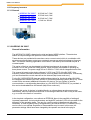
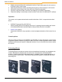
1.1 About NORD CON
NORD CON is a PC program intended to control and parameterizes the NORDAC vector
Frequenzumrichter inverters produced by Getriebebau NORD and option modules.
With NORD CON, up to 31 frequency inverters can be controlled simultaneously via the
integrated RS485 interface. Communication with the frequency inverters is handled by the PC's
serial interface.
To enable trial runs or system start-ups, the connected frequency inverters can be controlled
via the PC. The program also provides for continuous monitoring of the current status of the
frequency inverter while these activities are going on. Complete process sequences can be
developed using macros.
With NORD CON, you can perform, document, and save the parameter settings of a frequency
inverter which will be read out by the inverter or transmitted to it respectively. Parameter
databases can be created or manipulated off-line - i.e. without a frequency inverter being
connected.
The program further provides for remote control of the connected frequency inverters. For the
frequency inverter to be remote-controlled the operating unit of the type in question is simulated
on the PC. This is a convenient way of operating devices which are either difficult to access or
haven't got an operating unit themselves.
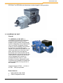
1.2 How to use NORD CON
Attention
For the parameterization and controlling of the devices with NORD CON, your PC requires a serial
interface.
1. Installation
Please start the installation program of NORD CON on the enclosed CD or load the installation
program from the Internet ("http://www2.nord.com/cms/de/documentation/software/softwareoverview.jsp"). Enter all necessary information and install NORD CON into the standard
directory.
2. Connect
If the frequency inverter is equipped with an RS232 optional interface, it can be directly
connected to the PC with a serial 1-1 cable. In this case, only one frequency inverter can be
connected. Each NORDAC vector Frequenzumrichter frequency inverter features an
integrated RS485 interface which can be activated via the control terminals. This interface
allows for configuration of a master/slave bus system with up to 31 devices max. For NORD
CON to be connected to such a bus, an RS232 - RS485 converter will be required.
BU 0000 GB
6
Introduction
Attention
If several devices are operated simultaneously, make absolutely sure that a unique USS address
is assigned to each of the devices connected, and that all of them have the same baud rate
setting (see also Operating Instructions of the frequency inverter type involved).
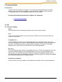
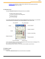
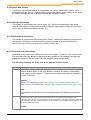
3. Run NORD CON
In order to start NORD CON, you use the shortcut "NORD CON start" or "Start->Program>Nord->NORD CON 2.1->NORD CON".
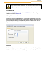
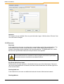
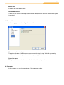
4. Setup of the communication module
In order to set the communication parameters, one must select the appropriate module in the
project view. Over the menu entry "Device-> Parameterize" the parameter dialog of the module
can be opened. In the edit field "Port" must be insert the correct COM port number. After that
you have to push the button "Apply". Additional settings are not necessary for the first
application and the window can be closed.
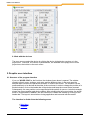
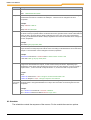
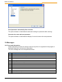
5. Bus scan
After the start of bus scan, all ready and connected devices are searched for. All found devices
are represented in the project tree and in the equipment overview. Subsequently, the first device
in the list is marked and the users can use all device-specific functions.
BU 0000 GB
7
NORD CON Manual
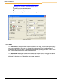
6. Work with the devices
The user can now select the device by clicking the device in the device overview or in the
project tree. Functions, like control or parametrizes, are available in the popup menu of the
project tree, the tool bar or the main menu.
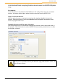
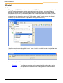
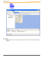
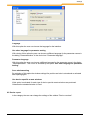
2 Graphic user interface
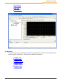
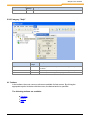
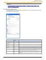
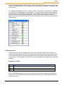
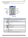
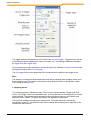
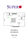
2.1 Structure of the program interface
If you run "NORD CON" for the first time, the window shown down is opened. The window
consists of main menu, toolbars, work area, and the different views. In the work area the
different editor windows like parameter windows or macros are shown. The windows can be
positioned freely or be docked at the sides of the work area. In order to change the position of a
docked window, click on the header bar of the window and keep the mouse button pressed.
Subsequently, the new position can be specified with the pointer of mouse. A colored rectangle
shows the current position and dock condition. After releasing the left mouse button, the actual
action is implemented. In addition, the user can dock or undock the window by clicking on the
header bar. The layout is stored when closing application and resumed with the restart.
The interface is divided into the following areas:
Main Menu
Toolbars
BU 0000 GB
8
Graphic user interface
Working Area
View "Project"
View "Log"
View "Remote"
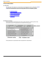
2.2 Main menu
The main menu is the central place for all actions of application. All editor windows register their
window-specific actions there. The actions are divided in categories.
Category "File"
Category "Edit"
Category "Device"
Category "View"
Category "Extras"
Category "Help"
BU 0000 GB
9
NORD CON Manual
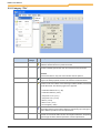
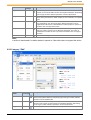
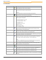
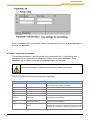
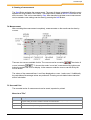
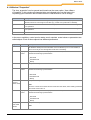
2.2.1 Category "File"
Name of action
Combinatio Icon Description
n of keys
New dataset
The action opens the parameter window for a new device. The user must
select the desired device in a previous window.
New macro
The action opens the macro editor with a new document. If the macro
window is already opened, the user can store the current document.
Attention:
In the current version, only one macro window can be opened!
PLC program
Open
The action opens the PLC editor with an empty document. If a PLC
program is already opened, the user can store the current document.
Ctrl + O
The action opens the file choice dialog in order to open a stored
document. The user selects a document type with the file filter, and selects
the file afterwards. The following types are supported:
Parameter dataset V1.27 (*.db)
Parameter dataset (*.ndbx)
Scope-File V1.27 (*.sco)
Scope-File V2.1 (*.scox)
Macro (*.ncmx)
Macro V1.27 (*.ncm)
PLC Program (*.awlx)
Save
Save as...
BU 0000 GB
Ctrl + S
The action stores the current document. The action is passed on to the
active editor window and implemented there. Depending upon the type of
editor, different operations can be implemented.
The action stores the current document with a new name. The action is
passed on to the active editor window and implemented there. Depending
upon the type of editor, different operations can be implemented.
10
Graphic user interface
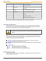
Name of action
Combinatio Icon Description
n of keys
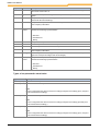
Export
Ctrl + E
Reopen
The action exports the data active editor windows into a file. The action is
passed on to the active editor window and implemented there. Depending
upon the type of editor, different operations can be implemented.
The action contains a submenu in which the opened last documents are
listed. History is limited to 5. When clicking on one of the files, it is opened
again.
Print
Ctrl + P
The action is passed on to the active editor window and implemented
there. Depending upon the type of editor, different operations can be
implemented. This action is deactivated if no editor window is opened or
the editor does not support the action.
Print preview...
The action opens a print preview for the active editor. Depending upon
editor, the printing preview can be differently developed. This action is
deactivated if no editor window is opened or the editor does not support
the action.
Quit
The action closes application.
Note:
A action is deactivated if no editor window is opened or if the editor does not support the action.
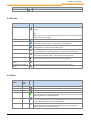
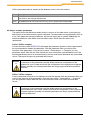
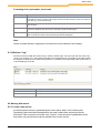
2.2.2 Category "Edit"
Name of
action
Combinati Icon Description
on of keys
Undo
Ctrl+Z
The action undoes the last action. The action is passed on to the active editor
window and implemented there. Depending upon the type of editor, different
operations can be implemented.
Cut
Ctrl+X
The action cuts the selected object and copies it into the clipboard. The action is
passed on to the active control member and implemented there. Depending
upon the type of editor, different operations can be implemented.
Copy
Ctrl + C
The action copies the selected object into the clipboard. The action is passed
BU 0000 GB
11
NORD CON Manual
Name of
action
Combinati Icon Description
on of keys
on to the active control member and implemented there. Depending upon the
type of editor, different operations can be implemented.
Paste
Ctrl + V
The action copies contents of the clipboard to the selected position. The action
is passed on to the active control member and implemented there. Depending
upon the type of editor, different operations can be implemented.
Note:
The action is deactivated if the current control element does not support this
action or the contents of the clipboard cannot be inserted.
Delete
Ctrl + Del
The action deletes the selected object. The action is passed on to the active
control and implemented there. Depending upon the type of editor, different
operations can be implemented.
Select all
Ctrl + A
The action selects all objects of the active control.
Replace...
Ctrl + H
The action searches for the indicated text and replaces these then by other text.
In a dialog, the appropriate option can be adjusted.
Up
Ctrl + U
The action shifts the delected object one position upward.
Down
Ctrl + D
The action entry shifts the delected object one position downward.
Note:
The action is deactivated if the current control element does not support this action.
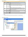
2.2.3 Category "Device"
BU 0000 GB
12
Graphic user interface
Name of action
Combin Icon Description
ation of
keys
Rename
With the action the user can change the name of the selected device.
Connect
F2
The action starts or stops the connection to the selected device.
Upload parameters
from device
F3
The action uploads the parameters from the device to the PC.
Download parameters F4
to device
The action downloads the parameters from the PC to the device.
Update firmware
The action starts the firmware upload program.
Control
F6
The action opens the "control" window of the selected device in the work
area. If the window was already opened, it is brought into the foreground.
Remote
F8
The action opens the "remote" window of the selected device. If the
window was already opened, it is brought into the foreground.
Parameterize
F7
The action opens the "Parameter" window of the selected device in the
work area. If the window was already opened, it is brought into the
foreground.
Oscilloscope
The action opens the "oscilloscope" of the selected device in the work
area. If the window was already opened, it is brought into the foreground.
PLC
The action entry opens the PLC editor of the selected device in the work
area. If the window was already opened, it is brought into the foreground.
Bus scan
Ctrl+F5
The action implements a network scan for the selected communication
module.
Note:
With a network scan, all devices are removed from the device list and all
device-specific windows are closed!
2.2.4 Category "View"
BU 0000 GB
13
NORD CON Manual
Name of action
Combinat Description
ion of
keys
Layout -> Standard
The action build the standard - layout of application for all views. The
position of the editor windows is not changed.
Layout -> Standard all
windows
The action build the standard layout of application for all windows including
the work area.
Device report
The action closes or opens the device report.
Project
The action closes or opens the view "project".
Log
The action closes or opens the view "log".
Remote
The action closes or opens the view "remote control".
Toolbar->Standard
The action closes or opens the toolbar "standard".
Toolbar->Device
The action closes or opens the toolbar "device".
Toolbar ->Start
The action closes or opens the toolbar "device".
Macro
The action opens a submenu. In this submenu, all special actions of the
macro editor are listed. The status as well as the execution of the actions is
incumbent on the active macro window. If no window is active, all actions are
deactivated.
Oscilloscope
The action opens a submenu. In this submenu, all special actions of the
oscilloscope are listed. The status, as well as the execution of the actions, is
incumbent on the active oscilloscope. If no window is active, all actions are
deactivated.
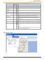
2.2.5 Category "Extras"
Name of action
Combinatio Description
n of keys
Settings
The action opens a window to edit the global settings of the program.
Log
The action opens a submenu. In this submenu all special actions of the view
"log" are listed. The status, as well as the execution of the actions, is
BU 0000 GB
14
Graphic user interface
Name of action
Combinatio Description
n of keys
incumbent on the view.
2.2.6 Category "Help"
Name of action
Combination Description
of keys
Help
F1
The action opens online help and selects the register map
"Contents".
Index
The action opens online help and selects the register map "Index".
About NORD CON
The action opens a dialog with the program information.
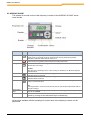
2.3 Toolbars
In the toolbars, the most common actions are available for fast access. By clicking the
appropriate symbol in the bar with the mouse, the desired action is specified.
The following toolbars are available:
Standard
Device
Start
BU 0000 GB
15
NORD CON Manual
2.3.1 Standard
Name of action
Icon
Description
New data set
The action opens the parameter window for a new device. Before the user can
open the dialog, the device must be selected.
New Macro
The action opens the macro editor with an empty document. If a macro is already
open, the user can store the current document.
Attention:
In the current version, only one macro window can be opened!
New PLC program
The action opens the PLC editor with an empty document. If a program is already
opened, the user can store the current document.
Open
The action opens the file dialog in order to open a stored document. The user
selects a document type with the file filter and select the file afterwards. The
following types are supported:
Parameter dataset V1.27 (*.db)
Parameter dataset (*.ndbx)
Scope-File (*.sco)
Scope-File V2.1 (*.scox)
Macro (*.ncmx)
Macro V1.27 (*.ncm)
PLC Program (*.awlx)
Save
The action stores the current document. The action is passed on to the active
editor window and implemented there. Depending upon the type of editor,
different operations can be implemented.
Cut
The action cut the selected object and copies it into the clipboard. The action is
passed on to the active control element and implemented there. Depending upon
the type of editor, different operations can be implemented.
Copy
The action copies the selected object into the clipboard. The action is passed on
to the active control element and implemented there. Depending upon the type of
editor, different operations can be implemented.
Paste
The action copies contents of the clipboard to the selected position. The action is
passed on to the active control member and implemented there. Depending
upon the type of editor, different operations can be implemented.
Note:
The action is deactivated if the current control element does not support this
action or the contents of the clipboard cannot be inserted.
Delete
The action deletes the selected object. The action is passed on to the active
control member and implemented there. Depending upon the type of editor,
different operations can be implemented.
Up
The action shifts the selected object a position upward.
Down
The action shifts the selected object a position downward.
Preview
The action opens a print preview for the active editor. Depending upon editor, the
printing preview can be differently developed. This action is deactivated if no
editor window is opened or the editor does not support the action.
Print
The action print the content from the active editor. This action is deactivated if no
editor window is opened or the editor does not support the action.
Fast print
The action print the content from the active editor without the print dialog. This
action is deactivated if no editor window is opened or the editor does not support
the action.
BU 0000 GB
16
Graphic user interface
Name of action
Icon
Settings
Description
The action opens a window to edits the global settings of the program.
2.3.2 Device
Name of action
Bus scan
Icon Description
The action implements a network scan for the selected communication
module.
Note:
With a network scan, all devices are removed from the device list and all devicespecific windows are closed!
Connect
The action connects or disconnects the connection to the selected device.
Control
The action opens "control" window of the selected device in the work area. If the
window was already opened, it is brought into the foreground.
Remote
The action opens "remote" window of the selected device. If the window was
already opened, it is brought into the foreground.
Parameterize
The action opens the "parameter" window of the selected device in the work
area. If the window was already opened, it is brought into the foreground.
Oscilloscope
The action opens the "oscilloscope" of the selected device in the work area. If
the window was already opened, it is brought into the foreground.
Plc
The action opens the PLC editor of the selected device in the work area. If the
window was already opened, it is brought into the foreground.
Upload parameters from
device
The action uploads the parameters from the device to the PC.
Download parameters to
device
The action downloads the parameters from the PC to the device.
2.3.3 Start
Name of
action
Combinati Icon Description
on of
keys
PLC settings
Compile
The action opens the settings of the PLC.
Shift + F7
The action starts the translation of a PLC program.
Programming Shift F8
The action loads a PLC program to the Device.
Run
F9
The action runs a PLC program or a macro. The action is passed on to the
active editor window and implemented there. Depending upon the type of editor,
different operations can be implemented.
Cancel
F11
The action terminates running a PLC program or macro. The action is passed
on to the active editor window and implemented there. Depending upon the type
of editor, different operations can be implemented.
Next
F12
The action executes the next instruction. The action is passed on to the active
editor window and implemented there. Depending upon the type of editor,
different operations can be implemented.
BU 0000 GB
17
NORD CON Manual
Name of
action
Combinati Icon Description
on of
keys
Debug
Shift + F5
The action runs the PLC program with the debug mode.
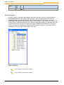
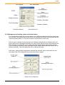
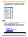
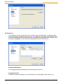
2.4 View "Project"
In View "Project", all devices of the project are shown in a tree structure. It can be closed or
opened with the main menu option "View->Project ". With the help of the mouse, you can
navigate between the individual devices. If the view possesses the input focus, you can
additionally select a device with the arrow keys "up" and "down ". If the pointer of mouse is over
a device entry, a reference about the type of device and fieldbus address is indicated. After the
selection of a device, the user can execute all actions with the tool bar as well as the popup
menu. If an action is shaded grey, the selected devices do not support. The popup menu is
opened by clicking the right mouse button in the view.
Status of device
The connection to the device is online
The connection to the device is offline
BU 0000 GB
18
Graphic user interface
Used topics:
Structure of popup menu, Structure of the program interface, Main menu, Toolbars, View "Log", View
"Remote", Docking and Undocking
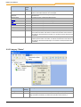
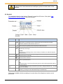
2.4.1 Structure of popup menu
The representation shows the popup menu of the project view. The menu always refers to the
selected nodes in the project tree.
Name of action
Combination
of keys
Rename
Upload parameters
from device
Description
With the action the user can change the name of the selected device.
F3
The action uploads the parameters from the device to the PC.
Download parameters F4
to device
The action downloads the parameters from the PC to the device.
Update firmware
The action starts the firmware upload program.
Control
F6
The action opens then "control" window of the selected device in the work
area. If the window was already opened, it is brought into the foreground.
Remote
F8
The action opens the „remote" window of the selected device. If the
window was already opened, it is brought into the foreground.
Parameterize
F7
The action opens the "parameter" window of the selected device in the
work area. If the window was already opened, it is brought into the
foreground.
BU 0000 GB
19
NORD CON Manual
Name of action
Combination
of keys
Description
Oscilloscope
The action opens the „oscilloscope" of the selected device in the work
area. If the window was already opened, it is brought into the foreground.
PLC
The action opens the PLC editor of the selected device in the work area. If
the window was already opened, it is brought into the foreground.
Bus scan
Ctrl + F5
The action implements a network scan for the selected communication
module.
Note:
With a network scan, all devices are removed from the device list and all
device-specific windows are closed!
2.5 View "Log"
In view "fault log", a list previous faults is indicated. The faults are sorted according to order of
occurrence. The list can be stored and deleted over the context menu (right mouse button).
Additionally, these actions are available in the main menu under the menu entry "Extras->Log".
Name of action
Description
Delete
The action deletes the list.
Save
The action stores the entries into a file.
2.6 View "Remote"
The view "remote" contains all windows of the function „Remote". The view opens automatically
when opening the first window and closes after closing the latest. The view can be docked or
undocked like all views to the work area. If the view was closed by the user, it can be opened by
the action "Remote" again. The new windows are always docked to the left side of the last
window. With the help of the mouse, it can be undocked or docked again. If the view is opened
for the first time with the menu "View->Remote", each device in the list the window "Remote" is
opened automatically.
BU 0000 GB
20
Graphic user interface
Note:
Windows of type "Remote" can be docked only into the view "Remote".
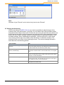
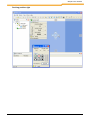
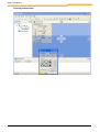
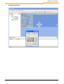
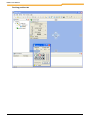
2.7 Docking and Undocking
With the new design of NORD CON, the user has the possibility to adapt the layout of the
surface to their own requirements. In principle, you can undock each view and editor window
and position them freely on the screen. For this, the user must press the left mouse button over
the title border and pull the colored rectangle to the desired position. After releasing the mouse
button, the view or editor windows remains in those positions as independent windows. With
the editor windows, there is additionally the possibility - with the popup menu, which opens
when clicking with the right mouse button on the title border, to undock the windows. The
docking functions are similar to the undocking functions. The colored rectangle indicates in
each case the current docking position.
Type of window
Rule
View of main window(e.g. Project, Logs,
Remote)
The views of the main window can be docked only to the left, right
and/or lower edge of the work area. Within these windows, there are
no rules and the user can select the position freely.
Editor window (e.g. Macro editor, Parameter The editor windows can only be docked into the work area. The
window, Oscilloscope)
adjustment is fixed however on down and/or above, or as register
map.
Views of the Macro editor
The views of the macro editor can be docked only to the macro
window. The adjustment here is fixed on left, right or down. Within
the views, no rules are defined.
Views of the oscilloscope
The views of the oscilloscope window can be docked only to the
oscilloscope window. The adjustment here is fixed on left, right or
down. Within the views no rules are defined.
„Remote" windows
"Remote" windows can only be docked to the view "Remote". Here
the adjustment is fixed on left.
BU 0000 GB
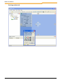
21
NORD CON Manual
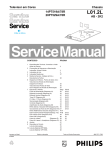
Docking position left
BU 0000 GB
22
Graphic user interface
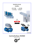
Docking position right
BU 0000 GB
23
NORD CON Manual
Docking position down
BU 0000 GB
24
Graphic user interface
Docking position up
BU 0000 GB
25
NORD CON Manual
Docking position tab
BU 0000 GB
26
Graphic user interface
3 Communication
3.1 Overview
In order to start a connection to a device, you must insert the appropriate communication
module in the project. After the installation, a USS module is configured. With the action
"Parameterize" the user can modified the parameters of the module.
Presently the following communication modules are supported:
USS over serial interface
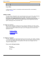
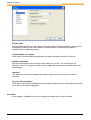
3.2 USS
3.2.1 General settings
Name
In the edit field, the user can assign a name for the communication module.
Port
In the communication window, you can choose the COM-Ports of the computer where the
inverter is connected to.
Telegram error
The user defines the max number of allowed telegram errors.Telegram errors occur if the
content of a telegram is not correct. That means the answer does not fit to the parameter order.
Normally, each parameter order is answered after 2 telegrams. The number of allowable
telegram errors is the number of tries before the error message appears.
Bus error
The user defines the max number of acceptable bus errors. The bus error appears in the case
when the receiving telegram or the sending telegram was wrong. Incorrect telegrams are
ignored. Here you can program the max number of incorrect bus telegrams before the error
message is generated. In an installation with many interferring signals, the setting of acceptable
errors should be programmed to a higher number.
Simulation of Hardware
With this feature, the user activates or deactivates the simulation of the connected hardware.
BU 0000 GB
27
NORD CON Manual
Attention:
All changes are only available if the user push the button "apply". With the button "Restore" then
user can undo all changes.
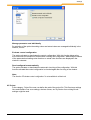
3.2.2 Bus scan
Baud rate
In the selection box, the user can choose the communication speed of the serial interface. The
same value must be chosen on the frequency inverter. When using multiple frequency
inverters, the setting must be identical on all connected devices. The Baud rates over 115200
Bit/s are user specific Baud rates and not by all devices are supported.
Attention
Older serial PC interfaces are sometimes not able to justify the accurate user specific Baud
rate. From this reason no connection can be made to the device.
Bus-Scan with all baud rates
With the action, the user activates or deactivates the bus scan with all baud rates. If the baud
rate of the connected device is unknown, the search with all baud rates can find the right one to
start communication.
Starting baud rate
In the selection box, the user can define the baud rate for start of the baud rate search.
Starting address
BU 0000 GB
28
Communication
In this field, the USS address can be defined, from where the search run of NORD CON starts
to find connected devices. All frequency inverters with lower address cannot be found by NORD
CON.
End address
In this field, the user can define the USS address for the ending of the search for connected
devices. All inverters with a higher address number cannot be found by NORD CON.
Stop all connected devices
With the action, the user can activate or deactivate the stopping (disable) of connected
devices. When this function is active, all enabled devices are stopped if the interface of the
device is programmed to "bus".
Automatic device search after start of program
With this action the user can activate or deactivate the automatic device search after start of
the program. When this function is active, NORD CON automatically starts the bus scan after
the program is started.
Attention
All changes are only available if the user push the button "apply". With the button "Restore" then
user can undo all changes.
BU 0000 GB
29
NORD CON Manual
4 Parameterization
4.1 Overview
All parameters of the frequency inverter that can be changed can also be changed by NORD
CON. All of the parameters can be stored and retransmitted to the frequency inverter.
Parameters which have been read out can be printed out for documentation purposes.
Parameter Viewing
How to manipulate parameters
Selective parameterization
Off-line Parameterization
Comparison
4.2 Parameter Viewing
Each parameter has a parameter name and a unique parameter number by which it can
directly be accessed. The parameters are devided into menu groups.
Each parameter has a parameter value and parameter characteristics:
BU 0000 GB
30
Parameterization
When a parameter has been selected, values of all parameter sets, if it can be set differently in
the sets, are displayed.
4.3 How to manipulate parameters
The selected parameter is read out and the value transferred to the 'Current Setting' box.
Management of the parameters of a frequency inverter is ensured by databases. These
databases can be stored, printed out or manipulated again at a later date.
Note
The menu "Parameterize" is indicated only if a parameter window were marked.
NORD CON features two ways of parameter manipulation:
Aktion
Place
Description
New
File -> New -> Dataset
The current database is re-initialized, in other words the
current and the new settings are deleted.
Open
File -> Open
Any database that was saved can be reopened.
Save
File -> Save
The current database is saved by the current name.
Save us...
File -> Save us...
The current database is saved with a new name.
Print preview...
File -> Print preview...
The current parameter settings are printed out.
Read all parameter or Parameterize -> Read -> All
Parameter
Read all
All of the parameters of the frequency inverter are read out
and entered into the database.
Read actual menu
group
Parameterize -> Read ->
Actual menu group
The parameters of the selected menu group are read out
and entered into the database.
Send new settings
Parameterize -> Send -> new All parameters for which a new value was entered in the
Values
'New settings' box are transmitted to the frequency inverter.
A selection is possible as to whether this operation is to be
BU 0000 GB
31
NORD CON Manual
Aktion
Place
Description
performed on all parameters or only on those belonging to
the current menu group.
Send Factory settings Parameterize -> Send ->
Reset values
The settings transmitted will be the default settings of all
parameters or of the parameters of the current menu group
respectively
Selection Enable
Parameterize -> Selection ->
Release
All of the parameters (or those included in the current
menu group respectively), are enabled.
Selection Disable
Parameterize -> Selection ->
no Release
None of the parameters (or of those belonging to the
current menu group), are enabled.
Standard
Button "Standard"
The default value is allocated to the currently selected
parameter.
Send
Button "Send"
The value "new setting" of the current parameter is
transferred to the inverter
Read
Button "Read"
The selected parameter is read out and the value
transferred to the 'Current Setting' box.
With the Auto-read option the selected parameter is read out automatically.
4.4 Selective parameterization
NORD CON allows for masking some parameters or other, a feature which may facilitate
manipulation or serve the purpose of restricting parameter readout or transmission to those
which remain unmasked or in other words have been filtered out.
Note
When a filter has been activated, all operations are executed only on those parameters which
are displayed.
Before any parameter can be masked the enable command must be inactivated. This can be
done using the checkbox preceding the parameter, or via the Selection menu. The Filter box
provides for the setting options mentioned below :
Selection only Only the enabled parameters are displayed (i.e. where the check box
preceding the parameter was clicked upon once).
No standard Only the parameters with a value that is different from the standard setting are
displayed.
Info parameters
Yes
Information parameters are displayed.
No
Information parameters are not displayed.
Only Information parameters are displayed exclusively.
4.5 Off-line Parameterization
Off-line parameterization implies that a database is manipulated which is not allocated to any
frequency inverter connected.
BU 0000 GB
32
Parameterization
Off-line parameterization is started via the database menu in the main window.
Name Description
New
A new database can be created. The new database is allocated to a frequency inverter
type which is set using a selection box.
Open Any database that was read into memory can be opened and manipulated.
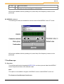
4.6 How to compare parameters
The report shows the differences and/or thing in common of two data record. In principle only
data records of one device family can be compared. The parameters are represented in form of
a list. If two parameter values are different, the line with a grey bar is marked. Additionally it is
examined whether a value differs from the default value. In this case the value is red
represented.
Online / Offline compare
Connect the device with NORD CON. Afterwards the parameter window must be opened and it
be recommended to readout all parameters. With the parameter filters you can limit the
selection of the parameters. Over the menu option " Parameterize - > Compare" you can
generate a report. After the call of the function the user must select a stored data record. If the
selected parameters are to be used as backup, the user must store afterwards the current data
record. Thereupon the report is generated and showed.
Attentio
As reference for the parameters and the default values the configuration of the
n
equipment is used. A data record with the configuration of the equipment not agrees
selected, possibly non-existent parameters are empty represented and marked as
difference.
Offline / Offline compare
For the comparison a stored or new data record must be opened. With the parameter filters you
can limit the selection of the parameters. Over the menu option " Parameterize - > Compare"
you can generate a report. After the call of the function the user must select a stored data
record.
Attentio
As reference for the parameters and the default values the configuration of the
n
opened parameter set is used. A data record with the configuration of the equipment
not agrees selected, possibly non-existent parameters are empty represented and
marked as difference.
BU 0000 GB
33
NORD CON Manual
5 Control
5.1 Overview
The program NORD CON can be used to control NORDAC vector Frequenzumrichter. To
use this function the inverter must be parametriesed in the right way. Because of different
settings of different inverter types the user must check the manual to find the right settings.
Before the inverter can be controlled the Bus-scan must be done. After the scanning process
has finished all connected inverter are displayed in the main window. Now the inverter to be
controlled can be chosen by mouse click. The window „control" can be opened via "device/
control (F6) in the main menu or via pull-down menu (right mouse click).
Now the control configuration of the inverter is read and checked with the standard setting
(setting/control/control configuration check). If the "control" of inverter limited or impossible there
will be a warning note on the screen.
In the window „Control" there are two versions available:
Standard
BU 0000 GB
The frequency inverter can be released and the setting value can be
increased or decreased.
C
Direction change and error acknowledge is
possible, too. o
n
t
r
o
l
34
Control
:
Detailed Control Mit diesem Fenster können sämtliche Steuerungsmöglichkeiten
ausgenutzt werden.
:
5.2 Standard control
Using the Standard Control the following functions are available:
Enable of the frequency inverter
Increase or decrease of the setting value
Change of direction
Error Acknowledge
To use this functionality, the inverter must be programmed for control via bus. You can find the
required parameter and settings in the manual available for each inverter type.
On the „Standard" display only the first setting value and first actual value are displayed. The
form of value is fixed for each configuration.
By pressing the button 'Detail' you can switch to the extended control function.
5.3 Detailed control
5.3.1 Overview
In the mode „Detailed Control" some extra functions are available:
BU 0000 GB
35
NORD CON Manual
Setting of control word and display of status word
Management of setting values and actual values
Sending of broadcast telegramme
Choice of different parameter sets
Automatic sending of control word and setting values
5.3.2 Control
The controlword is displayed as a hexadecimal value in the field „control word". By entering a
new value (hexadecimal) the user can change the control word. For a bit-coded setting of
control word the user can open up a new editorial window by pressing the button "control word
edit". In this window the control word is displayed in bits.
The status word is displayed hexadecimal in the screen „status word". To display the status
word in the bit resolution the button „bit orientated detail view" can be chosen. The status is
displayed in the status line of the status machine as clear text.
BU 0000 GB
36
Control
5.3.3 Management of setting values and actual values
For controlling the inverter the user can define up to 3 different setpoints and actual values (see
user manual). The setpoints and actual values are displayed according to the formatting (Button
„formatting setting value x"). The input of setpoins can be done in same way.
With the option „setting/control/ parameter set individual management" the setting values and
actual values can be managed individually. So setting values can be set for each parameter set.
With activation of a parameter set its setting values are transmitted to the frequency inverter.
This is necessary because for each parameter set the setting values and actual values can be
defined individually. The active parameter set is marked with a star.
If the option „setting/control/configuration automatically checked" was not activated, the user
can transmit the new configuration by pressing the button „update".
BU 0000 GB
37
NORD CON Manual
5.3.4 Formatting of Setpoint and/or actual value
Char
Name
Description
"%"
16 Bit standardised values
This standardisation transforms the setpoint/actual value to a 16
Bit standardised value. Standardisation means a scaling of
value range and is between -200% and 199% of a basic value
(e.g. nominal frequency).
"16"
16 Bit not standardised
By this formatting the setpoint and actual value are transformed
to 16 Bit value and transmitted to inverter and displayed without
any scaling.
"B"
DigInBits
By this Formatting the setpoint and actual value are transformed
to 8 Bit value. The bit status is displayed individual in check
boxes. In these check boxes each bit of setting value can be
changed.
"L"
32 Bit Low-Word
By this formatting the setpoint and actual value are taken as the
low word (16 Bit) of a 32 Bit word..If there is another setpoint or
actual value parametriesed with formatting "32 Bit High-Word",
then both values are combined in the top display. The setting
value can be given as a 32 Bit value.
"H"
32 Bit High-Word
By this formatting the setpoint and actual value are taken as the
high word (16 Bit) of a 32 Bit word. (see "32 Bit Low-Word").
"P"
16 Bit Posicon Arr control clamps
(SK7xx, Vector CT with Posicon)
By this formatting the setpoint and actual value are taken as the
„Posicon position array". The meaning of each bit you can find in
the Posicon manual. This option is only available for inverter with
Posicon functionality.
"I"
16 Bit Posicon Inc control clamps
(SK7xx, Vector CT with Posicon)
By this formatting the setpoint and actual value are taken as
„Posicon position increment array". You can find the meaning of
each bit in the Posicon manual. This option is only available for
inverter with Posicon functionality.
"32"
32 Bit standardised (SK7xx, Vector By this formatting the setpoint and actual value is taken as an 32
CT with Posicon)
Bit value without standadisation. This option is only available for
inverter with Posicon functionality.
5.3.5 Control word
The present status word is displayed with each bit in the window „status word". All bits are listed
in a table including bit number, name and status. According to bit value and function there is a
coloured LED shown.
Importance of LEDs:
LED
Importance
The Bit is set and/or the inverter is enabled.
An error is active or an enable signal is missing.
The Bit is not set.
BU 0000 GB
38
Control
With the standard setting the status word is read in cycles and the changes are displayed in the
window. For deactivating the cyclic reading switch off the function „automatic" in the menu (right
mouse click).
The window is docked left next to the „control" window. If the window should be free on desktop,
you should choose the popup menu "docking/no". To save space the window can be added as
an index card next to the index card „general". To do this the window must be moved (pressed
left mouse button) over the index card "general". After release of the button the window is
shown as an index card. With double click (left mouse button) on the index card you get back to
window mode.
5.3.6 Status word
The present control word is displayed with each bit in the window „status word". All bits are
listed in a table including bit number, name and status. According to bit value and function there
is a coloured LED shown. If inverter is programmed to USS control then the bits can be set by
control buttons. Each change of control word is sent immediately to the inverter (see „automatic
sending").
Importance of LEDs:
LED
Importance
The Bit is set and/or the inverter is enabled.
An error is active or an enable signal is missing.
The Bit is not set.
With the standard setting the control word is read in cycles and the changes are displayed in
the window. For deactivating the cyclic reading switch off the function „automatic" in the menu
(right mouse click).
BU 0000 GB
39
NORD CON Manual
The window is docked left next to the „control" window. If the window should be free on desktop,
you should choose the popup menu "docking/no". To save space the window can be added as
an index card next to the index card „general". To do this the window must be moved (pressed
left mouse button) over the index card "general". After release of the button the window is
shown as an index card. With double click (left mouse button) on the index card you get back to
window mode.
6 Remote
6.1 Overview
NORD CON can simulate the control unit of the respective frequency inverter. For this purpose
the frequency inverter transfers the content of its display to NORD CON. The key functions are
simulated on the PC and transmitted to the frequency inverter.
The frequency inverter can only be controlled via the Remote, if it has not previously been
enabled via the control terminals or via a serial interface (P509 = 0 and P510 = 0). In addition,
for this the parameter “PotentiometerBox Function” (P549) must not be set to function {4}
“Frequency addition” or function {5} “Frequency subtraction”.
Remote Standard
Remote NORDAC SK2xxE
Remote NORDAC SK7xxE/SK5xxE/SK300E
Remote NORDAC vector mc
Remote NORDAC vector ct
Note
BU 0000 GB
NORDAC vector Frequenzumrichter can be controlled via the keyboard (enable, setpoint +/-,
40
Remote
phase sequence etc.). As the timeout monitoring function is not active in this mode, any
breakdown of the connection between PC and frequency inverter will make further control
impossible.
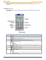
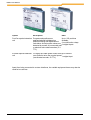
6.2 Standard
The standard window for the function "Remote" is used for all Devices, if the option "Use
device-specific remote windows" were not activated.
Name
Enable
Disable
Change dir
Up
Down
Enter
Icon
Description
Switching on the frequency inverter. The frequency inverter is now enabled with the set jog
frequency (P113). A preset minimum frequency (P104) may at least be provided.
Parameter >Interface< P509 and P510 must = 0.
Switching off the frequency inverter. The output frequency is reduced to the absolute
minimum frequency (P505) and the frequency inverter shuts down.
The motor rotation direction changes when this key is pressed. "Rotation to the left" is
indicated by a minus sign.
Attention:
Take care when operating pumps. screw conveyors, ventilators, etc. Block the key with
parameter P540.
Press key to increase the frequency. During parameterisation, the parameter number or
parameter value is increased.
Press the key to reduce the frequency. During parameterisation, the parameter number or
parameter value is reduced.
Press "ENTER" to store an altered parameter value, or to switch between parameter
number or parameter value.
Note:
If a changed value is not to be stored, the key can be used to exit the parameter without
storing the change.
Change Dir +
Stop
Enter + Start
By simultaneously pressing the STOP key and the "Change direction key” , an quick
stop can be initiated.
If the inverter is enabled via the "ON" key, the parameterisation mode can be
reached by pressing the ON and ENTER keys simultaneously.
All functions available with the operating unit (control box) of the frequency inverter can be
performed.
BU 0000 GB
41
NORD CON Manual
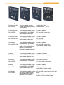
6.3 NORDAC SK200E
The window for remote control of the frequency inverters of the NORDAC SK 200 E series
looks like this:
Name
Enable
Disable
Change dir
Up
Down
Enter
Icon
Description
Switching on the frequency inverter. The frequency inverter is now enabled with the set jog
frequency (P113). A preset minimum frequency (P104) may at least be provided.
Parameter >Interface< P509 and P510 must = 0.
Switching off the frequency inverter. The output frequency is reduced to the absolute
minimum frequency (P505) and the frequency inverter shuts down.
The motor rotation direction changes when this key is pressed. "Rotation to the left" is
indicated by a minus sign.
Attention:
Take care when operating pumps. screw conveyors, ventilators, etc. Block the key with
parameter P540.
Press key to increase the frequency. During parameterisation, the parameter number or
parameter value is increased.
Press the key to reduce the frequency. During parameterisation, the parameter number or
parameter value is reduced.
Press "ENTER" to store an altered parameter value, or to switch between parameter
number or parameter value.
Note:
If a changed value is not to be stored, the key can be used to exit the parameter without
storing the change.
Change Dir +
Stop
Enter + On
By simultaneously pressing the STOP key and the "Change direction key” , an quick
stop can be initiated.
If the inverter is enabled via the "ON" key, the parameterisation mode can be
reached by pressing the ON and ENTER keys simultaneously.
All functions available with the operating unit (control box) of the frequency inverter can be
performed.
BU 0000 GB
42
Remote
6.4 NORDAC SK 700/500/300 E
The window for remote control of the frequency inverters of the NORDAC SK 700/500/300 E
series looks like this:
Name
Enable
Disable
Change dir
Up
Down
Enter
Icon
Description
Switching on the frequency inverter. The frequency inverter is now enabled with the set jog
frequency (P113). A preset minimum frequency (P104) may at least be provided.
Parameter >Interface< P509 and P510 must = 0.
Switching off the frequency inverter. The output frequency is reduced to the absolute
minimum frequency (P505) and the frequency inverter shuts down.
The motor rotation direction changes when this key is pressed. "Rotation to the left" is
indicated by a minus sign.
Attention:
Take care when operating pumps. screw conveyors, ventilators, etc. Block the key with
parameter P540.
Press key to increase the frequency. During parameterisation, the parameter number or
parameter value is increased.
Press the key to reduce the frequency. During parameterisation, the parameter number or
parameter value is reduced.
Press "ENTER" to store an altered parameter value, or to switch between parameter
number or parameter value.
Note:
If a changed value is not to be stored, the key can be used to exit the parameter without
storing the change.
Change Dir +
Stop
Enter + On
BU 0000 GB
By simultaneously pressing the STOP key and the "Change direction key” , an quick
stop can be initiated.
If the inverter is enabled via the "ON" key, the parameterisation mode can be
reached by pressing the ON and ENTER keys simultaneously.
43
NORD CON Manual
All functions available with the operating unit (control box) of the frequency inverter can be
performed.
6.5 NORDAC vector mc
The window for remote control of the frequency inverters of the NORDAC vector mc series
looks like this:
Name
Enable
Disable
Change dir
Up
Down
Enter
Icon
Description
Switching on the frequency inverter. The frequency inverter is now enabled with the set jog
frequency (P113). A preset minimum frequency (P104) may at least be provided. Parameter
>Interface< P509 and P510 must = 0.
Switching off the frequency inverter. The output frequency is reduced to the absolute
minimum frequency (P505) and the frequency inverter shuts down.
The motor rotation direction changes when this key is pressed. "Rotation to the left" is
indicated by a minus sign.
Attention:
Take care when operating pumps. screw conveyors, ventilators, etc. Block the key with
parameter P540.
Press key to increase the frequency. During parameterisation, the parameter number or
parameter value is increased.
Press the key to reduce the frequency. During parameterisation, the parameter number or
parameter value is reduced.
Press "ENTER" to store an altered parameter value, or to switch between parameter number
or parameter value.
Note:
If a changed value is not to be stored, the key can be used to exit the parameter without
storing the change.
BU 0000 GB
44
Remote
Change
Dir + Stop
Enter + On
By simultaneously pressing the STOP key and the "Change direction key” , an quick
stop can be initiated.
If the inverter is enabled via the "ON" key, the parameterisation mode can be reached
by pressing the ON and ENTER keys simultaneously.
All functions available with the operating unit (control box) of the frequency inverter can be
performed.
6.6 NORDAC vector ct
The following functions are available for remote control of the NORDAC vector CT series:
All functions available with the operating unit (control box) of the frequency inverter can be
performed.
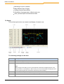
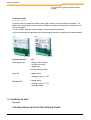
7 Oscilloscope
7.1 Overview
The oscilloscope function integrated inNORD CON can show process data of an NORDAC
vector Frequenzumrichter as an arithmetic chart.
Note:
This option is not available in all types of NORDAC vector ct and NORDAC vector mc!
The features of oscilloscope-function are:
BU 0000 GB
45
NORD CON Manual
Monitoring of up to 4 channels
Many different ways of trigger
Scaling of each measurement
Calculation of average values, effective value, etc.
Save, print and export of measurement data
7.2 Display
The oscilloscope function can measure and display 4 channels max:
The following settings can be done:
Name
Description
Auto
Automatic Scaling of all measured data
Offset
Selection of display detail (displace of all data in x- or y-direction)
Zoom
Display size (Zoom of all data)
Note:
With the right mouse button you can choose between modi 'Move' and 'Measurement', if the
mouse pointer is on the display. In 'Move' mode you can choose the detail of display by mouse
pointer by pressing the left mouse button while moving over the display.
Auto scrolling With this option during a recording the time axis is scrolled automatically to the last point.
Resolution
In this combination field the user can change the scaling of the time axis.
Comment
Additional information field, in that further information to the series of measurements to be stored
BU 0000 GB
46
Oscilloscope
Name
Description
can (max. 255 indications).
Cursor
Execution of measurement
7.3 Handling
Follow the next steps to execute a measurement:
1. Choise of channels
There is a popup menu to make the choice of the 4 channels. There is a color referring to each
channel. Each channel can be switched on and off by checkbox's. The resolution and offset can
be chosen for each channel separately. Displaying the results of measurement the values of
the vertical axis of each channel can be chosen and indicated.
Importance of measure value
Mesure value
Description
(=P[Number]) [Name]
The value of this measuring function is updated in the time slot pattern by approx.
100 ms and corresponds to the value indicated of the parameter.
[Name]
The value of this measuring function is updated in a time slot pattern by approx.
100 ms.
( P[Number]) [Name]
The value of this measuring function is updated in a time slot pattern by approx.
50 ms.
(~P[Number]) [Name]
The value of this measuring function is updated in a time slot pattern of approx.
250 µs.
2. Setting of trigger
BU 0000 GB
47
NORD CON Manual
The trigger starts the measurement. First choose the source of trigger. Trigger sources can be
measurement values, digital inputs, status of inverter, etc. The starting conditions are defined
by trigger level resp. trigger edge.
Time between two measured values is set by sampling rate. Numbers of measured values and
sampling rate define the time of sampling.
The Pre-trigger/Delay set the beginning of the measurement in relation to the trigger event.
Note:
The dynamic of measured values defines the best rate of sampling: fast changing values need
a low sampling rate. The number of measured values defines the time of sending the values
from inverter to NORD CON.
3. Sampling modes
The oscilloscope has 2 differently modes. The user can choose between "Single" and "Roll"
mode. The "Single" mode is the standard mode. In this mode starts a recording with the current
trigger settings. The recording time depends on the oscilloscope memory of the device and
amounts to max. 2000s. The values are noted in the adjusted sampling rate.
The roll mode makes a recording over larger period. The noted values are transferred
immediately to the PC. Therefore the user cannot change the sampling rate. It depends on the
speed of the transmission.
BU 0000 GB
48
Oscilloscope
4. Starting of measurement
The Start-Button activates the measurement. The event of trigger is detected. When the event
appears the record starts in the inverter. The transmission of data to NORD CON starts in the
same moment. This can be cancelled by Stop. After transferring all data a new measurement
can be started or new settings can be done by pressing the New-Button.
7.4 Measurement
After recording the measurement completely, measurements on the results can be done by
cursors.
There are two cursors available for this. The cursors can be moved by
. The choice of
cursor is done by
. To choose the mode `move`and `measurement`by right mouse
button the pointer has to be on display. In the measure mode the cursors can be set by left
mouse button.
The values of the measured lines 1 and 2 are displayed on cursor 1 and cursor 2. Additionally
the calculations like average values are performed. Pressing on calculation button starts the
shift of calculation.
7.5 Save and Print
The recorded series of measurement can be saved, exported or printed.
Menu item "File"
Name
Description
Open
A stored measurement data file can be chosen and loaded. During loading there is the choice if
only the setting should be loaded or all data of measurement.
Save as
The present measurement data and settings are saved with new name.
Export
The data can be exported as graphic file or data table.
BU 0000 GB
49
NORD CON Manual
Name
Description
Print
The lines of measurement are printed with present settings (colour of background: white).
Scope Offline
In Offline-mode (no inverter is connected) a saved measurement file can be loaded by
menuitem File|Open.
8 Macro editor
The macro editor is designed in order to provide simple process cycles. The surface offers the
possibility to create a macro by popup menus, toolbars or tool window. The individual
instructions can be shifted by drag n drop in the opinion. The built-in functions, as memory and
shop macros are integrated likewise into the popup menu. The macros are stored in the
standard format „XML ". The format of the previous version can be imported over the menu
option "opening" type of file „macro files V1.27".
8.1 Graphic user interface
More views are required for handling of the macro generator additionally to the editor window.
These views are available as tool windows. These windows can be docked or undocked to the
edge of the main window. With the menu option „view" of the popup menu all views can be
opened and closed.
Window "Variables"
Window "Properties"
Window "Log"
8.1.1 Window "Variables"
The view „variables" can be opened and closed over the menu option „View->Macro->Variables
". It is used for debugging. In this window after starting macros all variables and objects macros
with current rating are indicated. The expenditure of the value can be stopped in the view
„Properties->Display format".
There are the following formatting:
Decimal
Hexadecimal
Binary
BU 0000 GB
50
Macro editor
8.1.2 Window "Properties"
The view „properties" can be opened and closed over the menu option „View->Macro>Properties". In this window all characteristics are indicated to the current instruction.
Depending upon instruction the kind and number of characteristics can be change.
Name
Description
Result
With this characteristic one can change the object to give a new value. Only objects can be
selected, which one can assign a new value (e.g. control word, parameter or variable).
Operand
With this characteristic the user can select the object, which is to be used with an assignment
or an operation.
Operator
With this characteristic the user can select the object, which is to be used with an assignment
or an operation.
Comment
With this feature the user can add a comment to each command.
In the macro variables, control word or status word, setpoints, actual values or parameters are
called objects. Each of these objects has different parameters.
Object
Parameter Description
Variable
Name
The parameter specifies the name of the variable or absolute term. In the selection box
all variables already used are indicated. If one would like to put on a new variable, a
name not used yet must be registered with case insensitivity.
Display
format
The parameter specifies the display format in the view „variables ". It can be selected
between the following representations:
Decimale
Hexadecimale
Binary
Constant
Value
The parameter specifies the value of the absolute term.
Display
format
The parameter specifies the display format in the view „variables ". It can be selected
between the following representations:
Decimale
Hexadecimale
Binary
Control
Node ID
word or
status word
The parameter specifies the USS address of the desired device.
Note:
Since the current control word cannot be read from the device, when starting scheduler
the control word is set to 0.
Display
format
The parameter specifies the display format in the view „variables ". It can be selected
between the following representations:
Decimale
Hexadecimale
Binary
Set point
Node ID
and Actual
values
BU 0000 GB
The parameter specifies the USS address of the desired device.
Note:
51
NORD CON Manual
Object
Parameter Description
Since the current control word cannot be read from the device, when starting scheduler
the control word is set to 0.
Type
The parameter specifies the type of a value (see actual setpoint and actual value
types).
Format
The parameter specifies formatting from set point and/or actual values (see set point
and actual value of formatting").
Resolution
The parameter specifies the resolution to set point and/or actual values. It is used only
for the display in the editor.
Display
format
The parameter specifies the display format in the view „variables ". It can be selected
between the following representations:
Decimal
Hexadecimal
Binary
Parameter Node ID
The parameter specifies the USS address of the device.
ParamNo
The value specifies the number of the parameter.
Subindex
The value specifies the Subindex of the parameter.
Resolution
The parameter specifies the resolution to set point and/or actual values. It is used only
for the display in the editor.
Data type
The value specifies the data type of the parameter. In the current devices only 2 data
types are used (16 bits Integer and 32 bits Integer).
Display
format
The parameter specifies the display format in the view „variables ". It can be selected
between the following representations:
Decimal
Hexadecimal
Binary
Types of set point and/or actual value
Type
Description
Value 1 (16bit)
The 1.2 and/or 3 set point and/or actual value is to be used.
Value 12 (32bit)
The first and second set point and/or actual value is to be used as a 32bit value.
Note:
For this configuration the device must be accordingly configured accordingly (see „ Set point
and/or actual value formatting").
Value 13 (32bit)
The 1st and 3rd set point and/or actual value are to be used as a 32bit value.
Note:
For this configuration the device must be accordingly configured accordingly (see Set point
and/or actual value formatting ").
Value 23 (32bit)
The 2nd and 3rd set point and/or actual value are to be used as a 32bit value.
Note:
For this configuration the device must be accordingly configured accordingly (see „ Set point
and/or actual value formatting").
BU 0000 GB
52
Macro editor
Formatting of Set point and/or actual value
Formatting
Description
Normiert
This formatting interprets the set point and/or actual value as 16 bits standardized value.
Normalization means a scaling of the range of values and lies between -200% and 199% of a
base value (e.g. nominal frequency).
Unnormiert
IIn this formatting the set point or actual value is interpreted as 16 bits value, which is indicated
without scaling.
Lowword (32bit) This formatting specifies, that the first value is the Low word and the 2nd value is the High
word value 12 (32bit). This value can be selected only with the 32bit types.
Highword (32bit) This formatting specifies, that the first value is the high word and the 2nd value is the low word
value 12 (32bit). This value can be selected only with the 32bit types.
Note:
Please consider that the configuration of the device must be identical to the settings.
8.1.3 Window "Log"
All events of the scheduler are stored in log. In order to indicate logs, one must open over the menu entry
„View->Log" the view „Log". The window is likewise a tool window and can to the edge of the main window
be docked or undocked. In the window all log entries in a sorted list are represented. Here the last entry is
in at the beginning of the list.
Name of action
Description
Delete
The action deletes the list.
Save
The action stores the entries into a file.
8.2 Working with macros
8.2.1 Create a new macro
A new document (macro) is generated by the menu option „New" in the context menu.
Depending if document was opened before, the macro editor offers a storing of the old
document. If the user does not confirm with „Cancel", a new document is generated. At the
same time only one document can be opened in the current version.
BU 0000 GB
53
NORD CON Manual
8.2.2 Open a macro
Opening macros is implemented in the menu option „open" or with the combination of keys
„Ctrl+O ". Subsequently, a selection of files dialog opens, in which the user can select the
desired macro. If the user would like to open a macro of the previous version, he must change
the data type in the selection of files dialog accordingly.
8.2.3 Save a macro
Storing macros is implemented in the menu option „Save" or the combination of keys „a Ctrl+S
". This function is available however only for already generated documents. For all new
documents the function must be implemented „Save as… ".
The function is implemented in the menu option „Save as…". Subsequently, a selection of files
dialog opens, in which the user must select the file name as well as the path. After the
confirmation with „Save" the macro is stored. After the completion of the procedure the new
name macros in the title bar is indicated.
8.2.4 Copy from instruction
The function is implemented in the menu option „Copy" or the combination of keys „Ctrl+C ". It
copies the marked line into the clipboard of the editor. In the current version in each case a line
can be marked. Accordingly an instruction can be copied, too. The exception forms the
instruction for block. It can be copied only as a whole.
8.2.5 Cut from instruction
The function is implemented in the menu option „Cut" or the combination of keys „Ctrl+X ". It
copies the marked instruction into the clipboard of the editor. With the inserting cut out of the
instruction the old instruction is deleted from the document. The restriction to cut only one
instruction can exists also with this function.
8.2.6 Paste from instruction
The function is implemented in the menu option „Paste" or the combination of keys „Ctrl+V ". It
adds a before copied or low-cut instruction below the current position in the document. The
menu is deactivated if no instruction was copied or low-cut before. In the current version you
can insert each copied or low-cut instruction only once.
8.2.7 Delete from instruction
The function is implemented in the menu option „Delete" or the combination of keys „Ctrl + Del".
It deletes the marked instruction from the document.
BU 0000 GB
54
Macro editor
8.2.8 Search and replace
The function „Search and replace" is implemented in the menu „Search and replace" or the
combination of keys „Ctrl+H". Then the dialog „Search and replace" opens..Here you can insert
the search and replacement vocabulary and start the change procedure.
8.2.9 Shift up a instruction
The function is implemented in the menu option „Up". It shifts the marked instruction a line
upward. If the top line of document is marked no action is implemented. Shifting of instructions
can be done by drag n drop with the mouse, too.
8.2.10 Shift down a instruction
The function is implemented in the menu option „Down". It shifts the marked instruction one line
downwards. If the last line of the document is marked no action is implemented. Shifting
instructions can be done by by drag n drop with the mouse, too.
8.2.11 Generate new instructions
Generating of new instructions can be done in the menu option „Functions" in the context menu.
The new instructions are always inserted below the marked line. Subsequently, the user can
change the position of the new instruction (see „Upward and downward shift").
The following functions are to the user at the disposal in this version:
Name
Description
Allocation
The instruction assigns a new value to a macro object. The new value can be picked
out from another object, or the user defines a constant. According to standard the
line is inserted in the example 1. The parameters of the function can be changed in
the view „Properties".
Example:
Device 00 Control word = 047F hex // Assign to the control word the value 1151
Var1 = Device 00 Status word // Assign to the variable the value of the status word
Note:
An assignment of desired values can be implemented only within an instruction for
block.
Jump mark The instruction defines a jump mark in macro. With the help of the function „Goto" you can jump to
the place of the jump mark. According to standard the line is inserted in the example 1. The
parameters of the function can be changed in the view „Properies". The name of the jump marks are
to be changed in any case, as double names causes problems. The generator always jumps to the
first branch mark in the macro.
Example:
BU 0000 GB
55
NORD CON Manual
Name
Description
Label1: // Defined the label „Label1"·
or
Start: // Defined the label „Start"
Sleep
The instruction produces a break in the expiration macros. The time base is in „ms ". According to
standard the instruction is inserted in the example 1. The time can be changed in the view
„Properties".
Example:
Sleep 1000 ms // Wait 1s
or
Sleep 500 ms // Wait 0,5s
Goto
The instruction generates a jump in the macro. After activation of this instruction the generator jumps
into the line of the jump mark with the contained name. If the generator does not find a label with the
name, the line is ignored. Still if no label is defined in the macro, the menu entry is deactivated.
According to standard the first label is always registered. The names of the label can be changed in
the view „Properties".
Example:
Goto Start // goto jump mark „Start"
Condition
The instruction produces a conditioned jump in the macro. If the condition is true then the generator
jumps into the line of the jump mark with the name. According to standard the line is inserted in the
example 1. The instruction can be changed in the view „Properties"
Example:
if Device 00 Controlword == 047F hex then // Status word is of value 1150
Goto Start // then go to jump mark „Start"
Block
The instruction makes it possible to increases assignments in an instruction to implement. These
assignments are limited to the objects „control word" and set point values". Depending upon
configuration of the device and intended purpose the user can select between „control word with 1
set point value" , „control word with 2 set point values" or „control word with 3 set point values ".
Example: ·
Block
Device 00 Controlword = 1151 // assign to control word the value 1150
Device 00 Setpoint1 = 20,0 // assign to setpoint 1 the value 20
Mathematic These instructions realize some simple mathematical and logical operations of objects. The
s and logic computed value is assigned afterwards to an object. The instruction can be changed in the view
function
„Properties"
Example:
Var1 = Device 00 Controlword + 047F hex // Addition ·
Var1 = Device 00 Statusword AND 047F hex // logic „And "
8.3 Scheduler
The scheduler controls the sequence of the macros. For the module there are two options.
BU 0000 GB
56
Macro editor
Auto
With this option activated (automatic mode) after starting the scheduler line for line is
processed. If it is deactivated (single step mode) (menu entry „Next" or combination of keys
„F12 ") you must run each instruction manually.
Loop
With this option activated the macro in a continuous loop is implemented. That means after
doing the last instruction the scheduler jumps back to the beginning of the
macro.
Used topics:
Run a macro, Cancel a macro, Execute next instruction
8.3.1 Run a macro
The scheduler is started in the menu option „Start" or the combination of keys „F9 ". The
automatic mode is actively processed now line for line now. In the single step mode after
starting only the first line is implemented. For the next lines the user must call in each case the
action „next ones ". The scheduler can be started only again if the macro was processed or the
user has canceled the expiration. While the scheduler runs the characteristic of the instructions
cannot be changed.
8.3.2 Cancel a macro
The scheduler is terminated in the menu option „Cancel" or the combination of keys „F11 ".
8.3.3 Execute next instruction
This function can be found in the menu option „Next" or with the key „F12 ". It is available only in
the single step mode and instructs the scheduler to implement the next instruction in the macro.
If the last instruction was implemented, the scheduler is terminated automatically.
9 Settings
9.1 Overview
The user can change the current program settings with the menu option "Extras->Settings".
The attitudes are divided into the following categories:
Interface
Device report
Control
Communication
BU 0000 GB
57
NORD CON Manual
Project
Directories
Macro editor
Parameter
9.2 Interface
In this category the user can change the settings of the user interface. The following options are
available:
BU 0000 GB
58
Settings
Language
With this option the user can choose the language for the interface.
Use other language for parameter setting
With choice of this option the user can choose a different language for the parameter names in
the dialog "Parameterisation" in the choice box "Parameter language".
Parameter language
With this option the user can choose a different language for the parameter name in the dialog
„Parameterisation". This choice is activated by the option "Use other language for parameter
setting".
Save window setting
By activation of this option the window settings like position and size is stored and re activated
after opening again.
Use device-specific remote windows
If this option is activated, for each type of device special remote windows are produced.
Otherwise the standard window is used.
9.3 Device report
In the category the user can change the settings of the window "Device overview".
BU 0000 GB
59
NORD CON Manual
Border width
With the parameter the user can change the border width of the device display. A value can be
set between 0 and 10 pixels. More largely or if smaller value is registered, the largest or
smallest value is used automatically.
Optimal number of columns
If this option is selected than the application calculates the optimal number of columns.
Number of columns
With this parameter the user specifies a firm number of columns. The value can be set
between 1 and 10. If a larger or smaller value is registered, the largest or smallest value used
automatically.
Attention:
This parameter can be only changed, if the option "optimal number of columns" was not
selected.
Recover info parameters
If this option is selected, the adjusted info parameters of the device are stored and restored with
a bus scan or a restart of application.
9.4 Control
In the category „Control" the user can change the settings of the „control" window.
BU 0000 GB
60
Settings
Manage parameter sets individually
By activation of the option the setting values and actual values are managed individually in the
window „control".
Evaluate control configuration
The option activated or deactivates the control configuration. With this function being active
some functions are released or blocked after checking the configuration. Additionally the names
of the parameterised setting value functions or actual value functions are displayed in the
window in cleartext.
Read configuration automatically
The option activates or deactivates the automatic checking of the configuration. With this
function activated the control configuration is checked again after focusing of the window.
Note:
The function "Evaluate control configuation" is not available in all devices!
9.5 Project
In the category „Project" the user can define the path of the project file. This file stores settings
like used interface, bus scan settings, devices names, etc. By choice of an exisitng file old
settings might be used.
BU 0000 GB
61
NORD CON Manual
9.6 Directories
In this category you can set the directories, where the parameter data base, configuration files,
macro files and internal data bases are stored. To change one of the paths choose the directory
in the list with left mouse button and choose the new path by pressing the button „change". With
the buttons „Standard" you can choose a standard directory for each directory.
Parameter date bases
The changed parameter data bases are stored inside this directory.
Configuration files
These files contain all settings (e.g. used interface, bus scan settings, device name, etc.).
BU 0000 GB
62
Settings
Macro files
In these Files macros are stored.
Internal data bases
These files are used for internal program run. Here the parameter structure of the inverter types
is provided.
9.7 Macro editor
In the category you can do settings of macro editor.
Macro execution step by step
The option activates or deactivates the macro execution step by step. With this option being
activated each macro step must be activated separately (cycle/start).
Open last macro
The option activates or deactivates the function to load the last opened macro.
9.8 Parameter
In the category you can choose settings of the parameter window.
BU 0000 GB
63
NORD CON Manual
Read parameter automatically after selection
The option activates or deactivates the automatic reading of a parameter after selecting.
Show also the value with text parameter
The option activates or deactivates the display of numerical value with a text parameter.
10 Messages
10.1 Errors and informations
When a fault has occurred, the number of the error by which it is registered in the program is
displayed along with a concise error information.
The error messages are to be interpreted as follows:
No
Description
100
Parameter num. inadmissible
101
Parameter Value cannot be changed
102
Parameter limit exceeded
103
Error in sub-index
104
Not an array
105
Description cannot be changed
106
Description data does not exist
107
Time out receive data
108
Time out send data
109
Error in receive data
110
Different order and answer
200
Could not open serial port!
201
Could not close serial port!
BU 0000 GB
64
Messages
No
Description
202
First close old serial port!
203
Serial port is not open!
204
The settings of the communication module could not be set. Examine whether the current baud rate are
supported.
205
Buffer setup impossible!
206
Timeout setup impossible!
207
Communication not possible!
208
Internal object error!
210
Error writing file!
211
Telegramm not created!
212
No high-resolution Timer found!
213
No device found!
214
Only with 16 Bit SetPoint!
215
Inverter is running. Close ?
216
The firmware update can only be executed if the device address is zero!
217
The firmware update tool could not be started! Please install NORD CON again, in order to repair the
problem.
218
Please add a communication module!
219
Do you want to import the file into online view?
220
Here no device can be added!
221
Were found more to than 1 device at the bus! An update could cause problems. Would you like to
continue?
222
It comes to the inconsistency of the control data, if you use macros and control windows simultaneously!
Please close all control windows or the macro editor.
223
The transfer cannot be started, because the parameter editor is opened! Please close the editor and
restart the function.
224
The on-line help could not be found! Please install NORD CON again, in order to repair the problem.
225
The device cannot be disconnected, because still at least one window of the device is opened.
226
The file cannot be opened. The format of the file is unknown.
227
The file could not be read!
228
The format of the file is unknown!
229
The file was changed by the user!
230
The action cannot be executed, because the device is not connected!
231
The settings were changed. Would you like to store the changes?
232
Their computer does not support Chinese characters, therefore representation error can occur!
233
The value cannot be converted into INT16!
234
The current version of the device does not support a firmware update over the system bus!
235
The current version of the technology box does not support a firmware update over the system bus!
236
The device at address 0 doesn't support a firmware update over the system bus!
300
The path for the internal database have got to correct!
301
The path for the internal database is not correct. NORD CON will abort.
302
Error while open database!
303
FU-Type in database is not compatible!
304
FU-Type in database is different!
305
Save actual database?
306
Cannot open database!
307
Unallowed folder!
BU 0000 GB
65
NORD CON Manual
No
Description
308
Cannot store database!
309
Read all parameter immediately?
310
Please update NORD CON ! Faultless parameter transfer isn't guaranteed.
311
Printer isn't correct installed!
312
Sorry, two parameter window cannot run simultaneously. View the open window?
313
You have to close to parameter window to quit NORD CON !
314
You have to close to parameter window to make a Busscan!
400
The file could not be loaded, since the file version is unknown!
401
The file could not be loaded, since the file format is unknown!
402
The file was changed by the user!
403
Error open file!
405
No macro file!
406
Empty macro list!
407
Macro list executed!
408
Jump-Label not found!
409
The function cannot be executed, because the scheduler was started.
410
Would you like to save the changes in the macro?
411
The file was changed by the user! Would you like to open the file?
500
Load only the settings?
501
The types of device are different? Would you like to open the file?
502
The file could not be opened, because the version of the file format is unknown!
503
The file could not be opened, because the file format is unknown!
504
The file was changed by the user! Would you like to open the file?
600
The controlling of the device is reduced or not possible from the following reason: the controlword (P509)
is not for USS configures!
601
The controlling of the device is reduced or not possible from the following reason: the source of setpoint
1 (P510.0) is not for USS configures!
602
The controlling of the device is reduced or not possible from the following reason: the source of setpoint
2 (P510.1) is not for USS configures!
603
The controlling of the device is reduced or not possible from the following reasons: the controlword
(P509) and the source of setpoint 1 (P510.0) are not for USS configures!
604
The controlling of the device is reduced or not possible from the following reasons: the controlword
(P509) and the source of setpoint 2 (P510.1) are not for USS configures!
605
The controlling of the device is reduced or not possible from the following reasons: the source of
setpoint 1 (P510.0) and 2 (P510.1) are not for USS configures!
606
The controlling of the device is reduced or not possible from the following reasons: the controlword
(P509), the source of setpoint 1 (P510.0) and 2 (P510.1) are not for USS configures!
700
The action cannot be executed, because the connection to the device is interrupted!
800
The parameter transfer was successfully executed
801
Errors occurred during the parameter transfer!
802
The parameter tranfer was cancelled by user!
803
Errors occurred during the parameter transfer! Would you like to save?
804
The parameter tranfer was cancelled by user! Would you like to save?
900
Maximally 5 variables can be registered into the watch list!
901
The file must be stored, before you can translate it. Would you like to create a new file?
902
The file could not be opened, because the file format is unknown!
903
The file could not be read!
904
The file was changed by the user! Would you like to open the file?
BU 0000 GB
66
Messages
11 Getriebebau Nord
11.1 NORD In Short
NORD is a manufacturer of high-performance mechanical and electrical drive components
which are distributed worldwide.
In fact we have sales agencies in 48 countries from which the following drive varieties can be
obtained: helical in-line, shaft-mount, bevel, worm and planetary reducers for outputs between
0.12 kW and 200 kW and for torques from 10 Nm up to 60.000 Nm.
Corporate history
Frequency inverters
BU 0000 GB
67
NORD CON Manual
11.2 NORD corporate history
Ever since NORD was founded in 1965, all companies of the group have adhered to the
common strategy of satisfying the demands of our customers.
BU 0000 GB
1965
The company is founded
1977
A modern gear-producing factory is built
1979
Subsidiaries are established all over the world
Expansion of the worldwide presence by setting up assembly shops
1980
From now on all NORD gearboxes are manufactured as "UNICASE" types,
according to the company's own design
1983
A plant is constructed where NORD can produce its own electric motors
1985
Construction of a factory for the production of frequency inverters
1992
A factory for the machining of iron and steel castings is established
1997
Another NORD motor production plant is built in Italy
1998
A new assembly shop is built in France
2000
New assembly plants in Great Britain and Austria
2001
New assembly plant in China
2002
Expansion of Gadebusch machining plant (app.7.200 m²)
2003
Construction of an assembly plant in Russia
2004
Construction of a new motor plant in Italy
2005
40 years of Nord Gear
Opening of the high-rack storage system in Bargteheide
Germany Construction of a new assembly centre in China.
2006
New production plant for electronic products opened in Aurich, Germany
2007
Construction of new assemly plants in India and Czech Republic
2008
Expandation at Getriebebau NORD, Bargteheide
- Construction of a parking garage
2009
Expandation at Getriebebau NORD, Bargteheide
68
Getriebebau Nord
- Construction of a next high rack storage
- Construction of a assembly center for industrial gear units
2010
BU 0000 GB
Expandation at Getriebebau NORD, Bargteheide
- Expansion of a assembly center for industrial gear units
69
NORD CON Manual
11.3 Frequency Inverters
11.3.1 General
NORDAC SK 200 E
NORDAC SK 300 E
NORDAC SK 500 E
NORDAC SK 700 E
0,25 kW bis 7,5 kW
0,55 kW bis 4,0 kW
0,25 kW bis 7,5 kW
1,5 kW bis 160 kW
11.3.2 NORDAC SK 200 E
General information
The NORDAC SK 200E is based on the tried and tested NORD platform. These devices
feature a compact design with optimum control characteristics.
These devices are provided with sensorless vector current control which in combination with
asynchronous three-phase motor types constantly ensures an optimised voltage-to-frequency
ratio. This has the following significance for the drive: Peak start-up and overload torques at
constant speed.
This series of devices can be adapted to individual requirements by means of extension
modules. Due to the numerous setting options, these inverters are capable of operating all
three-phase motors. The power range is from 0.25kW to 7.5kW with an integrated mains filter.
This manual is based on the device software V1.2 R0 (see P707) of the SK 200E. If the
frequency inverter used has a different version, this may lead to some differences. If necessary,
you can download the current manual from the Internet (http://www.nord.com/).
For the SK 215E/225E/235E there are additional descriptions for functional safety (BU 0230),
the integrated AS interface (BU 0200, Section 5.4) and the positioning system (BU 0210). These
contain all the necessary additional information for start-up. If a bus system is used for
communication, a corresponding description (e.g. BU 0220 für PROFIBUS DP) is provided, or
this can be downloaded from the Internet (http://www.nord.com/).
Typically, this series of devices is installed directly on a three-phase asynchronous motor.
Alternatively, there are optional accessories for mounting the devices in the vicinity of the motor,
e.g. on a wall or the frame of a machine.
In the simplest configuration, even without an EEPROM, there is the possibility of setting all
important parameters via two potentiometers and eight DIP switches. LEDs are provided for the
diagnosis of the operating status. The use of a control module is therefore not absolutely
necessary. In order to gain access to all parameters, the internal RS232 PC interface (RJ12)
can be used, or an optional SimpleBox or ParameterBox may be used. In this case, the
parameter settings which have been changed by the operator are stored in the plug-in
BU 0000 GB
70
Getriebebau Nord
EEPROM. The EEPROM must then always remain plugged in during operation.
11.3.3 NORDAC SK 300 E
General
The NORDAC trio SK 300E is a
combination of geared motor and highly
functional frequency inverter which
enables process-oriented, decentralized
system configurations to be implemented
very conveniently. Designed to ensure
maximum ease of handling and operation
the inverter is user-friendly in every
respect. The inverter is provided with what
can be described as an "electronic type
plate" which the motor will read and
permanently store with the effect that the
inverter data are not lost to the motor even
if the inverter is removed. As the inverter
can be upgraded with a number of
modules within the scope of a well
thought-out concept, appropriate control
components are available to establish the
optimal configuration for any process to
be controlled.
Outputs between 0.55 kW … 4.0 kW (3
AC 380 … 480V) are provided.
Basic features
High protection class (IP66)
Class B integrated line filter
BU 0000 GB
71
NORD CON Manual
Modular sub-assemblies with an adequate number of inputs and outputs for the inverter to
be linked to other control loops
Optional potentiometer function permitting the frequency to be set directly on the inverter
Automatic saving of data in the motor due to the "electronic type plate"
Universal, easily accessible connection unit enabling user-friendly manipulation
Parameter setting is conveniently carried out with a control box or a dedicated PC software
Operation
The inverter can be parameterised and controlled with either of the 2 components described
below:
NORDAC Parameter-Box (SK PAR 2H)
Handy operating device with a display and a set of operating buttons enabling the inverter
to be parameterised and controlled right on the spot where the drive is installed.
NORD CON software
Convenient software for easy operation, control and parameterisation of the inverter from a
PC.
Control options
With its modular architecture, the NORDAC trio SK 300E is a device allowing for a great variety
of expansion options. Indeed it is possible to add to the basic control equipment various custom
interfaces with inputs and outputs in adequate numbers or one or the other bus access module
as required.
Technology Boxes
Technology Boxes are optional modules with which additional functionality can be added to the
inverter, dependent on requirements. As well as bus connections for all marketed BUS
systems, a module with switch and potentiometer is available for direct speed adjustment for
on-site operation of the inverter. The inverter^s high protection grade is maintained with every
technology box.
BU 0000 GB
72
Getriebebau Nord
Technology Boxes
Potentiometer-Box This box enables infinitely
1 switch left-o-right
variable
speed
setting
directly
SK TU2-POT
Potentiometer0 ... 100 %
at the inverter.
Profibus module
SK TU2-PBR
This interfaces enable control 1 Profibus- Interface
of the NORDAC trio SK300E 2x 5 pole M12 system plug
via the serial Profibus port.
Profibus module
SK TU2-PBR-KL
This interfaces enable control 1 Profibus- Interface
of the NORDAC trio SK300E 1x 8 pole plug
via the serial Profibus port.
1x SUB-D9
Profibus DP
SK TU2-PBR-24V
This interfaces enable control 1 Profibus- Interface
of the NORDAC trio SK300E 2x 5 pole M12 system plug
via the serial Profibus port. By
1 external 24V voltage supply
external 24V supply the bus
partner is contacted still,
although the supply voltage of
inverter itself is switched off.
CANbus
SK TU2-CAO
This interfaces enable control 1 CANopen- Interface
of the NORDAC trio SK300E 2x 5 pole M12 system plug
via the serial CANopen port.
DeviceNet
SK TU2-DEV
This interfaces enable control 1 DeviceNet- Interface
of the NORDAC trio SK300E 1x 5 poliger M12 system plug
via the serial DeviceNet port.
InterBus
SK TU2-IBS
This interfaces enable control 1 InterBus- Interface
of the NORDAC trio SK300E 2x 5 poliger M12 system plug
via the serial Interbus port.
1 externe 24V voltage supply
AS-Interface
SK TU2-AS1
This interfaces enable sensors
and cctors. Additionally the
parameter setting of 300E is
possible via Asi-Interface.
BU 0000 GB
2x 5 pole M12 system plug for actor and
sensor
1x 5 pole M12 system plug for ASInterface and 24V auxilary voltage
73
NORD CON Manual
1x 5 pole M12 system plug 24V auxilary
voltage
Customer Units
Customer units are optional modules, which offer a variety of control inputs and outputs. The
options for controlling the inverter can be modified according to requirements. A customer unit
can be integrated
in each inverter. After the mains voltage is connected and switched on,
this is automatically recognized by the inverter and the functions contained are made available..
Custom interface
Data
Basic equipment
1 brake control module
1 multifunction relay
1 digital input
RS 485 interface (M12)
Basic I/O
3 digital inputs
1 analogue input 0...10V
Standard I/O
4 digital inputs
2 analogue input 0...10V
1 analogue/digital
11.3.4 NORDAC SK 500 E
General
THE NEW NORDAC SK500E OFFERS NEW SOLUTIONS
BU 0000 GB
74
Getriebebau Nord
The new NORDAC SK500E family
of inverters in bookshelf design
brings intelligent technical solutions
with a competitive price. With its
wide range of functionality and
options there are virtually no
limitations in the field of applications.
System start-up of the SK500E on
standard applications is convenient
with its easy parameterization and
fully automatic intelligent motor
identification.
The SK500E offers outputs from
0.25 kW (1/3 hp) to 7,5 kW (10 hp)
and accepts AC inputs from 200 ...
480 V. 1 and 3 phase.
The sophisticated mechatronic concept of the NORDAC SK500E provides convenient
mounting and quick installation with removable (plug/unplug) termination strips.
Local control is provided with the following ergonomic options:
SIMPLE BOX, CSX, extra-user-panel with "Single-Button-Operating"
CONTROL BOX, for parameter management
PARAMETER BOX, Plain language text panel (in 6 different languages).
SK500E – basic features
Four separate parameter sets switchable on-line
High starting torque (up to 400%) and precise speed control due to vectorial current control
without a feedback sensor.
Automatic motor parameter identification
7 control inputs, that can be configured for digital or analog signals.
2 digital outputs, 1 analog output
Integrated brake chopper and separate control of electromagnetic motor brake
PID-controller and process-controller
RS 232 & RS 485 Interface
32 fixed frequencies
Motorized pot function
Limit switch control
Flying Start
Parameters of the NORDAC SK500E can be accessed and changed via parameter box or the
optional NORD CON programming software. Serial communication between the inverter and
the computer is achieved using standard interface cables and connectors All actual operating
values can be monitored to optimise drive adjustment. All diagnostic values can be viewed for
easy troublehooting and quick assessment. Inverter faults and total operating hours are also
viewable in a historical log to aid in troubleshooting and maintenance.
BU 0000 GB
75
NORD CON Manual
Available interface options include:
PROFIBUS
CAN
CANopen
DeviceNet
INTERBUS
AS-Interface
Enhanced control functions have been integrated into the SK500E for maximum inverter
performance and reliability. The EMC suppression circuitry allows the integration of SK500E in
domestic areas.
For added motor safety and protection the SK500E monitors input voltage, output current,
motor temperature and motor brake.
SK520E – INVERTER FOR THE UPPER CLASS
The SK520E model with its expanded capabilities is the perfect fit for more complex
applications.
SK520E - expanded features:
Encoder interface (TTL)
CANopen Interface
2 additional digital inputs
2 additional digital outputs
11.3.5 NORDAC SK 700 E
The new NORDAC SK 700E
type series was developed on
the basis of the proven vector
type series to which a couple
of sophisticated features have
been added. Compared with
previous models, the
modularity has been
substantially increased and the
control performance
optimised.
BU 0000 GB
76
Getriebebau Nord
Sensorless vectorial current (ISD) control
These devices are provided with sensorless vectorial current control system which will
constantly ensure an optimised voltage-to-frequency relation based on the simulated operation
of an asynchronous three-phase motor.
Thus maximum starting and overload torques are available to the drive while speed remains
constant.
Owing to the huge variety of setting options these inverters are capable of controlling any threephase motor on the market.
Outputs between 1.5 kW and 160 kW (3 AC 380 ... 480 V) are provided.
Basic Features:
High starting torque (up to 400%) and precise control of the motor speed owing to vectorial
current control without a sensor being involved
Variable configuration according to customer requirements using special equipment boxes,
custom interfaces, and special extensions
Easy and convenient installation, parameterisation, and system start-up
The great variety of setting options allow for configuration of any commonly available threephase motor. For NORD geared motors the parameter values are preset in the factory.
Installation of one unit right beside the other in the cabinet without the need of spacing
Admissible ambient temperature up to 50°C
(S3 duty cycle)
Integrated line filter for limit curve A (up to 22kW)
Automatic measurement of the stator resistance
Four separate parameter sets switchable on-line
Analogue PI / PID controller
Programmable relay outputs
Programmable d.c. braking
Integrated braking chopper for four-quadrant operation
Adjustable ramp smoothing
Scalable analogue output, 0 to 10 volt
Detachable parameterisation and display module
Multilingual clear text display and data storage function
Optionally available: incremental shaft encoder feedback for high-precision speed control
Optionally fitted with integrated positioning control for exact positioning of the drive
Variable equipment boxes (Technology Units)
... are snapped on to the inverter externally. They are used to control the inverter or read out
current operating values right on the device.
BU 0000 GB
77
NORD CON Manual
Option
Description
Parameter box
Used to start up, parameterise, configure and control the inverter via
full text instructions.
Optional: snap-on installation
Control Box
Used like the parameter box, however with the information displayed
in a more simplified fashion.
Optional: snap-on installation
Potentiometer
Enables the drive to be controlled directly on the frequency inverter.
Optional: snap-on installation
CAN bus module
Profibus module
RS 232
InterBus
CANopen
DeviceNet
AS-Interface
With these optional CAN / CANopen / Profibus DP / RS 232 /
DeviceNet / Interbus /AS-Interface modules the SK 700E can be
controlled and parameterised (without a serial port).
Optional: snap-on installation
Custom interfaces
... are optional slide-in modules for insertion into slots which are located inside the inverter
housing. Having been plugged in they are identified by the inverter automatically. The cables are
connected using direct push-lock-type connectors with pull-off spring terminals (ZEC). With
them the devices can very conveniently be connected.
BU 0000 GB
78
Getriebebau Nord
Option
Description
Basic I/O unit
Simplest custom interface providing optimum transition to the
equipment of the user.
Standard I/O unit
Greater diversification of the functions executed by control signals,
including USS bus selection.
Multi I/O unit
Highest functionality of digital and analogue signal processing.
USS unit
This interface allows for control of the NORDAC SK 700E via the serial
USS port.
CAN bus unit
This interface allows for control of the NORDAC SK 700E via the serial
CAN bus port.
Profibus unit
This interface allows for control of the NORDAC SK 700E via the serial
Profibus DP port.
Extension units
... turn the standard inverter into a high-precision control device that will ensure variable
response of the system to any conditions and requirements.
Special extensions are used in the inverter in addition to the custom interfaces.
BU 0000 GB
79
NORD CON Manual
Option
Description
Data
PosiCon special extension Programmed positions are
Up to 252 positions
unit
approached and held based on
available
position sensing and displacement
2 x multifunction relays
calculation. Actual position values are
detected by means of incremental and/6 x digital inputs
or absolute value shaft encoders (5 V
TTL).
Encoder special extension For highly accurate speed control from Up to 250kHz
unit
zero speed to twice the nominal speed 1 x digital input
(incremental encoder, 5V TTL).
Apart from being connected to custom interfaces, the variable equipment boxes may also be
used for bus access
BU 0000 GB
80
Index
Index
Interface
........................................................................
and views
8
Introduction
........................................................................ 6
Iterations
........................................................................28
A
About........................................................................15
AboutNORD
........................................................................
CON
6
L
Language
........................................................................58
Layout
........................................................................
B
Standard
........................................................................
13
Baud........................................................................
rate
28 Log ........................................................................
13, 14, 20
Border
........................................................................
width
59
Bus error
........................................................................27
Bus scan
........................................................................
12, 17
C
M
Macro
........................................................................13
Macro
........................................................................
editor
57
Main........................................................................
menu
9
Cancel
........................................................................17 Makro
........................................................................50
Close........................................................................10 Makro-Generator
........................................................................50
Communication
........................................................................
27, 57 Menu........................................................................
8, 12, 14, 15
Compile
........................................................................17
Configuration
........................................................................27
Connect
........................................................................
12, 17
Control
........................................................................
12, 17, 34, 57, 60
Controlword
........................................................................38
Copy........................................................................
11, 16
Cut ........................................................................
11, 16
D
N
Name
........................................................................27
New ........................................................................10
New ........................................................................
Macro
16
New ........................................................................
parameter set
16
New ........................................................................
PLC program
16
Next........................................................................17
NORD
........................................................................
CON
6
Debug
........................................................................17 NORDAC
........................................................................
Delete
........................................................................
11, 16
SK300
........................................................................
E
71
Detail........................................................................
Control
35
SK500
........................................................................
E
74
Device
........................................................................
report
13, 57, 59
SK700
........................................................................
E
76
Directories
........................................................................57
Docking
........................................................................21
Down........................................................................16
E
End address
........................................................................28
Errors........................................................................
and error information
64
Execute
........................................................................
bus scan with all baud rates
28
Export
........................................................................10
F
O
Open........................................................................
10, 16
Oscilloscope
........................................................................
13, 17
P
Parameter
........................................................................
27, 31, 57
Auto-Read
........................................................................
31
Edit
........................................................................
31
Filter
........................................................................
32
Off-line
........................................................................
32
First ........................................................................
steps
6
Overview
........................................................................
30
Formatting
........................................................................
of actual value
38
Viewing
........................................................................
30
Formatting
........................................................................
of setpoint
38 Parameter
........................................................................
download to device
12, 17
Frequency
........................................................................
inverters
70 Parameter
........................................................................
language
58
H
Help ........................................................................15
How ........................................................................
to use NORD CON
6
I
Parameter
........................................................................
upload from device
12, 17
Parameterize
........................................................................12
Parameterizes
........................................................................17
Paste
........................................................................
11, 16
PLC ........................................................................
12, 17
Index........................................................................15 Port ........................................................................27
Interface
........................................................................
57, 58 Print........................................................................10
BU 0000 GB
81
NORD CON Manual
Print ........................................................................
preview
10 USS........................................................................27
Programming
........................................................................17
Project
........................................................................
13, 18, 57
Popupmenu
........................................................................
19
V
View........................................................................20
Q
Quit ........................................................................10
R
Remote
........................................................................
12, 13, 17, 20, 40, 43
SK
........................................................................
200 E
42
SK
........................................................................
300 E
43
SK
........................................................................
500 E
43
SK
........................................................................
700 E
43
Standard
........................................................................
41
Vector
........................................................................
ct
45
Vector
........................................................................
mc
44
Rename
........................................................................12
Replace
........................................................................11
Run ........................................................................17
S
Save........................................................................
10, 16
Save........................................................................
as
10
Scope
........................................................................12
Select
........................................................................
all
11
Settings
........................................................................
14, 16
Shift ........................................................................
down
11
Shift ........................................................................
up
11
Simulate
........................................................................
hardware
27
SK200E
........................................................................70
SK220E
........................................................................70
SK230E
........................................................................70
Standard
........................................................................16
Standard
........................................................................
Control
35
Start........................................................................
address
28
Start........................................................................
baud rate
28
Statusword
........................................................................39
Stop ........................................................................
all found devices
28
T
Telegramm
........................................................................
error
27
Toolbar
........................................................................
13, 15, 16, 17
Device
........................................................................
13
Standard
........................................................................
13
Start
........................................................................
13
U
Undo........................................................................11
Undocking
........................................................................21
Up ........................................................................16
Update
........................................................................
firmware
12
BU 0000 GB
82
Intelligent Drivesystems, Worldwide Services
Getriebebau NORD GmbH & Co. KG
Rudolf-Diesel-Str. 1
D- 22941 Bargteheide
Fon +49 (0) 4532/ 401 - 0
Fax +49 (0) 4532/ 401 - 253
[email protected]
www.nord.com