1
Chapter
10
Implinks and Endpoints
Implementation links and endpoints are important concepts in the
SOMT method (described in the SOMT Methodology Guidelines
starting in chapter 69 in the User’s Manual). This chapter describes
the tool support for implinks and endpoints. The following topics
are covered:
July 2003
•
Link concepts
•
How endpoints and links are visualized
•
How to create links
•
The Entity Dictionary window
•
Link commands in menus
•
The Paste As command
•
The Link Manager tool
Telelogic Tau 4.5 User’s Manual
,um-st1
427
Chapter
10
Implinks and Endpoints
Link Concepts and Overview
The SDL suite supports creating and maintaining links between different objects in a system. Such links are used to show relations between
objects in different documents. Objects that may be linked are:
•
Text fragments in text documents
•
Graphical objects and symbols in OM, SC, HMSC, SDL and MSC
diagrams (but not text fragments in such diagrams)
•
Documents in the Organizer structure.
Implinks
The link concept in the SDL suite is designed to support the SOMT
method, further described in the SOMT Methodology Guidelines starting in chapter 69 in the User’s Manual. In SOMT, an important relation
is that one object can be seen as an implementation of another object.
For this reason, links between objects are often referred to as implementation links, or implinks. For instance, a textual object in the requirement analysis may be implemented as an object class in the system analysis, and later as a process type in the design model.
Implinks are the result of a design decision taken during the development of a system. Using implinks enables traceability between the different models and phases, so that the usage of a particular object or concept can be followed from requirements all the way down to code. Another important aspect of implinks is that they facilitate consistency
checks between the different models.
Links and Endpoints
A link has two endpoints, one at each of the objects that are linked together. Endpoints can be created for objects without creating a link, i.e.
endpoints are entities separate from links. When a link is created, endpoints are created automatically, if they do not already exist. It is possible to have any number of links connected to an endpoint. Endpoints
and links can be created from the Organizer and the editors.
Links are bidirectional, i.e. they can be traversed (followed) in both directions. Even so, a link has a “default” direction, defined when the link
is created, to indicate the intended direction. This means that an endpoint is either a logical “from” endpoint, or a logical “to” endpoint.
428
,um-st1
Telelogic Tau 4.5 User’s Manual
July 2003
Link Concepts and Overview
A link has a name and optionally a comment. The name indicates the
type of link, e.g. “implementation link”, and the comment is used to describe the link.
Link File
Information about endpoints and links is stored in a central link file (extension .sli), which is referred to from the Organizer’s system file.
This approach makes it easy to get an overview of existing endpoints
and links, and to make consistency checks. The link file is saved whenever the system is saved. The link file, and its defined links, are managed by a dedicated tool, the Link Manager (see “Tool Support and Operations” on page 432).
Information about endpoints are also stored in the individual documents. However, link information is only stored in the link file.
Local Link File
To make it easier to use the endpoint and link features in a multiuser environment, the concept of a local link file is provided. This is a personal
link file for one user, storing all changes made to endpoint and link information compared to the global file, the master link file. A controlled
merge operation is provided to update the master link file with the local
link file information. These operations are available as services in the
Telelogic Tau Public Interface (see “Link File Services” on page 552 in
chapter 12, The Telelogic Tau Public Interface).
July 2003
Telelogic Tau 4.5 User’s Manual
,um-st1
429
Chapter
10
Implinks and Endpoints
Visualization of Endpoints and Links
By default, endpoints are marked in a special way in the editors and in
the Organizer. The markers are slightly different depending on whether
or not any links are connected to the endpoint.
Endpoints in Graphical Editors
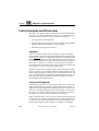
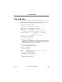
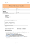
In the SDL Editor and the SDL suite diagram editors, the endpoint
marker is a small triangle in the upper left corner of the object’s enclosing rectangle. The triangle is filled if the endpoint has any links connected to it.
Figure 132: Endpoints with and without links
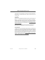
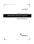
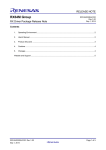
For lines in the SDL, OM. SC and HMSC diagrams, the marker appears
on the name or signal list associated with the line. In SDL diagrams, it
is also possible to create endpoints on other text elements associated
with the line.
Figure 133: Endpoints on lines and text attributes
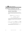
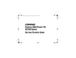
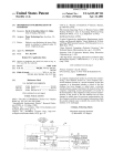
For lines in MSC diagrams (messages, timers, create requests), the
marker normally appears at the “start” end of the line.
430
,um-st1
Telelogic Tau 4.5 User’s Manual
July 2003
Visualization of Endpoints and Links
Figure 134: Endpoints on MSC lines
You can hide the endpoint markers by changing the option Show Link
Endpoints in the Editor Options in the View menu, or by setting the editor preference ShowLinks to off.
Note:
Endpoint markers are never shown when printing a diagram.
Endpoints in Text Editors
In the Text Editor, endpoints are shown as underlined text, regardless if
they have links connected to them or not. The endpoint text can be
shown as normal text by changing the option Show Link Endpoints in
the Editor Options in the View menu, or by setting the Text Editor preference ShowLinks to off.
In the Emacs editor (on UNIX), endpoints without links are by default
shown as blue, underlined text, whereas endpoints with links are shown
as bold, blue, underlined text. The default font faces can be changed; see
“Type Faces for Endpoints” on page 403 in chapter 7, Emacs Integration.
In MS Word (in Windows), endpoints without links are shown as blue,
underlined text, whereas endpoints with links are shown as bold, blue,
double underlined text.
Endpoint text is always shown as normal text when printing a text document.
July 2003
Telelogic Tau 4.5 User’s Manual
,um-st1
431
Chapter
10
Implinks and Endpoints
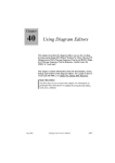
Endpoints in the Organizer
In the Organizer, the endpoint marker appears in the same way as in the
graphical editors, i.e. a triangle in the upper left corner of the document
icon.
Figure 135: Endpoints in the Organizer.
The endpoint markers are always shown in the Organizer, and they are
also shown when printing the Organizer window.
Tool Support and Operations
Operations on endpoints and links are supported in the Organizer, the
diagram editors, the Text Editor and the Link Manager.
In the editors, the possible operations are identical and can be found in
the Link submenu of the Tools menu (see “Link Commands in the Tools
Menus” on page 442). The operations include:
•
•
•
•
Creating and deleting an endpoint
Creating and deleting a link
Traversing a link (bringing the other endpoint into view)
Opening the Link Manager
In the Organizer, the available operations in the Tools menu are limited
to creating and deleting an endpoint, and opening the Link Manager.
In the editors, it is also possible to open the Entity Dictionary from the
Window menu. The Entity Dictionary lists all endpoints in the system,
together with the documents making up the Organizer structure. It is
mainly intended for re-use of entity names, but also supports creating
links. See “The Entity Dictionary” on page 434.
The Link Manager shows all endpoints and links in the system. It supports the following main operations:
•
•
•
•
432
,um-st1
File operations on the link file
Creating and deleting links
Editing a link’s direction, name and comment
Performing consistency checks on endpoints and links
Telelogic Tau 4.5 User’s Manual
July 2003
Creating Links
It is not possible to create and delete endpoints in the Link Manager. For
more information about the Link Manager, see “The Link Manager” on
page 462.
Creating Links
There are basically three different ways to create links:
1. Manually, by linking together two endpoints.
This operation requires two already existing endpoints. The endpoints may have been created manually, or as an effect of creating a
link earlier.
This operation is only available through the use of the Link Manager. See “Create Link” on page 468.
2. Manually, by linking together an endpoint and a selected object.
This operation requires an already existing endpoint (selected in the
Entity Dictionary), and a selected object in an editor. The endpoint
may have been created manually, or as an effect of creating a link
earlier. The selected object does not have to be an endpoint.
This operation is available from the editors and the Entity Dictionary. See “Link > Create” on page 442.
3. Automatically, by copying and pasting an object (Paste As).
This operation does not require any existing endpoints. An object is
first selected and copied in an editor. The object is then pasted in an
editor or in the Organizer by using the Paste As menu choice. This
transforms the object, if necessary, and automatically creates a link
between the copied and pasted object.
This operation is available from the SDL, MSC, OM and Text Editors and the Organizer and supports the SOMT method. See “The
Paste As Command” on page 448. It is not available in the SC/HMSC Editor.
July 2003
Telelogic Tau 4.5 User’s Manual
,um-st1
433
Chapter
10
Implinks and Endpoints
The Entity Dictionary
The Entity Dictionary Concept
The purpose of the Entity Dictionary is to provide easy access to names
of entities being used in the system, and a possibility to reuse these
names in all parts of the system. The entities that the Entity Dictionary
manage are all the link endpoints defined in the system, as well as all
diagrams, documents and modules found in the Organizer structure.
The Entity Dictionary is accessible from the SDL suite editors. The
names in the Entity Dictionary are available for reuse in all texts and
graphical objects found in the graphical diagrams. However, the Text
Editor does not support reuse of texts in text documents.
The Entity Dictionary is also used for creating links between objects
and existing endpoints when using the editors.
Relations to Editor Windows
The Entity Dictionary is implemented as a modeless dialog window.
There is not a single Entity Dictionary window, but one window for
each type of diagram (SDL, MSC, OM, SC, HMSC and text). All Entity
Dictionary windows contain exactly the same information, and all the
windows are updated when a change is made. The reason for having an
Entity Dictionary window for each editor type is that operations in the
window apply to the object currently selected in the respective editor.
Since there might be several editor windows showing different diagrams/documents, there is a need to define the current window. This is
the editor window that will be associated with the Entity Dictionary,
and all operations will act on the current window. The current window
is the editor window where the user last performed a menu command or
a mouse click detected by the editor.
The editor associated with an Entity Dictionary window is known as the
parent editor. The editor type is reflected in the window title of the Entity Dictionary window, thus making it possible to distinguish the different Entity Dictionary windows, and to determine the parent editor
that the Entity Dictionary operations will affect.
434
,um-st1
Telelogic Tau 4.5 User’s Manual
July 2003
The Entity Dictionary
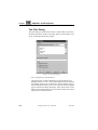
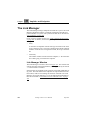
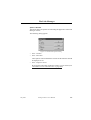
Entity Dictionary Window
The Entity Dictionary Window can be opened from all of the editors
through the use of the menu choice Entity Dictionary in the Window
menu.
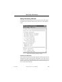
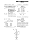
Figure 136: The Entity Dictionary window
Contents and Structure
The window lists all the defined link endpoints, following the structure
of diagrams and files in the Organizer. By default, every item in the Organizer is repeated, and the indentation of items is also repeated. All Organizer items and link endpoints listed in the window are known as entities in the Entity Dictionary.
July 2003
Telelogic Tau 4.5 User’s Manual
,um-st1
435
Chapter
10
Implinks and Endpoints
Below each Organizer item, the link endpoints defined in that item are
listed with indentation:
•
Below each SDL diagram, the symbols marked as link endpoints are
listed.
•
Below each MSC diagram, the instances, messages and other symbols marked as link endpoints are listed.
•
Below each OM diagram, the names of all the classes, instances and
other symbols marked as link endpoints are listed.
•
Below each text document, the text fragments marked as link endpoints are listed.
For an Organizer item that contains both sub-documents and link endpoints, the endpoints are listed first, followed by the sub-documents.
It is possible to hide the Organizer items to display only the link endpoints; see “The Filter Dialog” on page 440 for more information.
The information in the Entity Dictionary is updated whenever a link
endpoint is created, changed or cleared in any of the editors or the Link
Manager, or when the Organizer structure is modified.
Entity Icons
Each entity has an associated icon that identifies the type of the entity,
i.e. the type of the endpoint object. Entities that already have an established icon in the Organizer or the Index Viewer use the same icon in
the Entity Dictionary, with a few exceptions. The icons specific to the
Entity Dictionary are:
Diagram Heading
Diagram Extended Heading
OM Class
OM Object
OM Association
436
,um-st1
Telelogic Tau 4.5 User’s Manual
July 2003
The Entity Dictionary
OM Aggregation
OM Generalization
SC Transition
MSC Message
MSC Create
MSC Timer Set
(H)MSC Reference
HMSC Start
HMSC Stop
HMSC Connection
Text symbols and text fragments
Textual Notation
The type and name of an entity is shown to the right of the icon. For entities containing a name, such as diagram symbols, this name is listed.
For other symbols and text fragments, the first 25 characters are shown.
The cases when a diagram reference symbol, a diagram heading, or an
Organizer document is an endpoint will result in duplication of information in the Entity Dictionary. To distinguish between such endpoints
and the structure of Organizer documents, the following textual notations are used:
•
Link endpoints are listed using a plain font face.
•
Documents and other Organizer items that are not endpoints are listed using an italic font.
•
Endpoints that are diagram reference symbols contain the word
“Reference” after the diagram type.
•
Endpoints that are diagram headings has the word “Heading”, “Additional Heading” or “Extended Heading” as the entity type.
Figure 136 on page 435 shows examples of these textual notations.
July 2003
Telelogic Tau 4.5 User’s Manual
,um-st1
437
Chapter
10
Implinks and Endpoints
Operations in the Entity Dictionary
The Entity Dictionary window does not contain a menu bar. Operations
are available as quick buttons or as popup menus.
Quick Buttons
The following quick buttons are special to Entity Dictionary window.
Close
Close the Entity Dictionary window.
Create Link
Create a link between the endpoint selected in the Entity Dictionary and
the object selected in the parent editor. The quick button is dimmed if
not two such selections are present. If the parent editor is a Text Editor,
the selected text must be an already existing endpoint.
The Create Link dialog is opened; see Figure 139 on page 443.
Insert
Insert the text in the selected symbol in the Entity Dictionary at the insertion point in the object selected in the parent editor. The quick button
is dimmed if not two such selections are present. If text is selected in the
parent editor’s text window, this text is instead replaced.
This button is not available in the Text Editor’s Entity Dictionary.
Replace
Replace the text content of the object selected in the parent editor with
the text in the selected symbol in the Entity Dictionary. The quick button is dimmed if not two such selections are present.
This button is not available in the Text Editor’s Entity Dictionary.
Undo
Undo the most recent text operation in the Entity Dictionary (Insert, Replace, Undo). The quick button is dimmed if the selection in the parent
editor has changed to another object.
This button is not available in the Text Editor’s Entity Dictionary.
Filter
Filter the information listed in the Entity Dictionary. See “The Filter Dialog” on page 440 for more information.
Show Editor
Raise the parent editor window.
438
,um-st1
Telelogic Tau 4.5 User’s Manual
July 2003
The Entity Dictionary
Popup Menus
The following tables lists the available operations in the popup menus
of the Entity Dictionary window.
On the Window Background
Appears when no symbol is selected and the menu is invoked in an area
not containing any symbols.
Expand All
Expands all collapsed symbols.
Collapse All
Collapses all symbols; only root symbols will
be shown. Collapsed symbols are indicated
with a small triangle directly below the symbol.
Show Editor
Raises the parent editor’s window.
On a Document Symbol
Appears if an Organizer document symbol is selected, or the menu is invoked where a document symbol is selectable.
Expand
Expands a collapsed symbol one level down.
Expand Substructure Expands the entire substructure of the symbol.
Collapse
Collapses the substructure of the symbol.
On an Endpoint Symbol
Appears if an endpoint symbol is selected, or the menu is invoked where
an endpoint symbol is selectable.
Show Definition
Brings up an editor window, or the Organizer
window, where the endpoint is selected.
Double-Clicks
If there is a selection in the parent editor and a symbol in the Entity Dictionary is double-clicked, the text of the symbol is inserted in the parent
editor. A double-click thus corresponds to using the Insert quick button;
see “Insert” on page 438. This functionality is not available in the Text
Editor’s Entity Dictionary.
July 2003
Telelogic Tau 4.5 User’s Manual
,um-st1
439
Chapter
10
Implinks and Endpoints
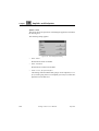
The Filter Dialog
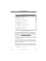
The Filter dialog is opened when the Filter quick button is pressed in
the Entity Dictionary window. The Filter dialog controls what is to be
shown in the Entity Dictionary window.
Figure 137: The Filter dialog
•
Select endpoint types that should be
This option menu controls whether the selected endpoint types
should be hidden or shown. The possible endpoint types are shown
in a multiple selection list, in which any number of items can be selected. If the option menu is set to shown, only the selected endpoint
types are listed in the Entity Dictionary. If the option menu is set to
hidden, the selected endpoint types are hidden, and the ones not being selected are thereby shown.
440
,um-st1
Telelogic Tau 4.5 User’s Manual
July 2003
The Entity Dictionary
•
Show endpoints with filter
This text field is a pattern for matching endpoint names. Only endpoints whose names match the pattern are shown in the Entity Dictionary. The string has the same syntax as a normal UNIX file pattern, and may contain the elements ‘*’ (zero or more characters), ‘?’
(exactly one character), and ‘[...]’ (any character within the brackets).
An empty text field matches any name, i.e. it is equal to a single ‘*’.
•
Organizer Structure
This option controls whether the documents making up the Organizer structure are shown. If not set, only endpoints are listed in the Entity Dictionary.
•
Diagram type name
This option controls whether the diagram type names in the Organizer structure are shown. If not set, only the names of the diagrams
are shown in the Entity Dictionary.
•
Endpoint type names
This option controls whether the endpoint type names are shown. If
not set, only the names of the endpoints are shown in the Entity Dictionary.
•
Default
Resets the Filter dialog to its default settings, but does not close the
dialog. The default settings are:
–
–
–
–
July 2003
The endpoint type list contains no selection.
The endpoint type option menu is set to hidden.
The endpoint name filter is empty.
The three Show options are set.
Telelogic Tau 4.5 User’s Manual
,um-st1
441
Chapter
10
Implinks and Endpoints
Link Commands in the Tools Menus
This section describes the link-related commands that are available in
the Link submenu in the Tools menu of the Organizer and all SDL suite
editors.
Note:
None of these commands are possible to Undo.
The Organizer only supports a subset of the link commands.
The Link submenu contains the following menu choices:
•
•
•
•
•
•
Link > Create
Link > Create Endpoint
Link > Traverse
Link > Link Manager
Link > Clear
Link > Clear Endpoint
Link > Create
This menu command creates a link between the object selected in the
editor and the object selected in the Entity Dictionary. If two such objects are selected, the Create Link dialog is opened (see Figure 139 on
page 443). The editor object does not need to have a link endpoint defined to be able to create a link, i.e. only one of the objects need to be
present in the Entity Dictionary. It is possible to create a link to itself.
Note:
In the Text Editor, the selected text must already be a link endpoint.
It is not possible to create links to text that is not an endpoint.
If no object is selected in the editor, or no endpoint is selected in the
Text Editor, the menu command is dimmed.
If no object is selected in the Entity Dictionary, or the Entity Dictionary
has not been opened, a warning dialog is issued (see Figure 138) and the
Entity Dictionary window is opened or raised. When the dialog is
closed and the instructions given in it are followed, the Create Link dialog is opened.
442
,um-st1
Telelogic Tau 4.5 User’s Manual
July 2003
Link Commands in the Tools Menus
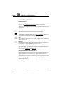
Figure 138: The Create Link warning
The Create Link dialog looks like this:
Figure 139: The Create Link dialog
•
Link <editor object> to/from <entity dictionary object>
The two selected objects are listed at either side of the to/from radio
buttons. The radio buttons control which of the objects that is to be
the logical to and from object. Link to is the default.
•
Link name
The name of the link. A name can be entered or edited in the text
field, or be selected from the associated option menu. The five latest
July 2003
Telelogic Tau 4.5 User’s Manual
,um-st1
443
Chapter
10
Implinks and Endpoints
used link names when creating links will be available in the option
menu, and the name in the text field is preset to the latest used link
name. A link name must be specified.
•
Link comment
An optional comment text, to be provided by the user. The text box
is initially empty.
•
Create
Creates a link between the two objects. The link will be visible in
the Link Manager and the endpoint objects are marked as being an
endpoint with at least one link, i.e. if the editor object was not already an endpoint, it will be created.
If the Entity Dictionary window was opened because of the Create Link
command, it will stay up until the user explicitly closes it.
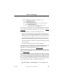
Link > Create Endpoint
This menu command defines the currently selected object as a link endpoint. The endpoint is immediately added to the Entity Dictionary and
the Link Manager. The object is marked as a link endpoint in the invoking tool – an editor or the Organizer. (See “Visualization of Endpoints
and Links” on page 430.)
This command is dimmed if not exactly one object that can be defined
as a link endpoint is selected, or if the object already is an endpoint.
This command is also available in the popup menus of all editors and
the Organizer.
Link > Traverse
This menu command traverses an existing link from the currently selected object. This is done by opening the tool where the other link endpoint is defined (an editor or the Organizer) and selecting the other endpoint object.
This command is dimmed if more than one object is selected, or if the
selected object has no links defined.
This command is also available in the popup menus of all editors and
the Organizer, as Traverse Link.
444
,um-st1
Telelogic Tau 4.5 User’s Manual
July 2003
Link Commands in the Tools Menus
If there is only one link defined from the object, that link is traversed,
as described above. If more than one link exists, a dialog showing all
links is opened and one of the links has to be selected.
Figure 140: The Traverse Link dialog
The dialog presents a list of all links to and from the object in the following form:
From | To <type and name of linked object>, <file name>
The type and name of the linked object follow the same notation as in
the Entity Dictionary; see “Textual Notation” on page 437. The file
name of the document where the linked object is found contains a path
if the file is not in the Organizer’s Source Directory.
•
To traverse a link, select the link and click the Traverse Link button,
or double-click the link.
Link > Link Manager
This menu command opens or raises the Link Manager window. If exactly one object is selected and this object is a link endpoint, this endpoint will be selected and made visible in the Link Manager. This command is never dimmed.
For more information about the Link Manager, see “The Link Manager”
on page 462.
July 2003
Telelogic Tau 4.5 User’s Manual
,um-st1
445
Chapter
10
Implinks and Endpoints
Link > Clear
This menu command removes one or more links to or from the currently
selected object. However, the link endpoints are preserved. This command is dimmed if more than one object is selected, or if the selected
object has no links defined.
Caution!
Removing a link cannot be undone.
A dialog showing all links is opened and one or more of the links has to
be selected.
Figure 141: The Clear Link dialog
The links to and from the object are listed in the following form:
From | To <type and name of linked object>
The list of links is a multiple selection list, in which one or more links
can be selected. When a selection is made in the list, the Clear button
becomes active.
To remove links, select the links in the list and click the Clear button.
A link is removed from both endpoint objects, but the link endpoints
themselves are not removed. If either of the endpoint objects had only
this link defined, and no others, the mark of the object changes to indicate that the object is only an endpoint with no links defined. For information on how to remove an endpoint, see “Link > Clear Endpoint” on
page 447 (below).
446
,um-st1
Telelogic Tau 4.5 User’s Manual
July 2003
Link Commands in the Tools Menus
Link > Clear Endpoint
This menu command removes the link endpoint from the currently selected object, and subsequently all links connected to the endpoint.
This command is dimmed if more than one object is selected, or if the
selected object is not an endpoint.
If the selected object has no links connected to the endpoint, the endpoint is removed without further user interaction. The endpoint is removed from the Entity Dictionary and the Link Manager. The object is
no longer marked as a link endpoint in the invoking tool (an editor or
the Organizer).
Note:
In the Text Editor, this command can also be used to reduce the extent of an already existing endpoint. If the selection only indicates a
partial range of the endpoint, at the start or end of the endpoint, a dialog will appear allowing you to choose whether to remove the entire endpoint, or just remove the selected part of the endpoint from
the selection.
If a partial range in the middle of the endpoint text is selected, the
only possibilities are to remove the entire endpoint or cancel the operation.
If the selected object has one or more links connected to the endpoint, a
warning dialog is opened, since the operation of removing a link cannot
be undone:
July 2003
Telelogic Tau 4.5 User’s Manual
,um-st1
447
Chapter
10
Implinks and Endpoints
The Paste As Command
The command Paste As is available in the Edit menu of the Organizer
and in the SDL suite editors (except for SC or HMSC diagrams).
The Paste As command is used to paste a copied object as another object, and at the same time create an implementation link between the
copied and pasted objects. It is also possible to paste a cut object, but in
this case no link can be created.
It is possible to paste the object into an editor different from the one the
object was copied from. This requires a transformation of the object according to the user’s choice.
Paste As supports the SOMT method, which governs the possible transformations for a particular object. See the SOMT Methodology Guidelines starting in chapter 69 in the User’s Manual for information and advice on when to use a particular transformation.
Note:
The normal Paste command in the Edit menu is very different from
Paste As. A normal paste can only be performed in the same editor
as the object was copied from, and the pasted object is as far as possible an identical copy of the object.
The Paste As Process
The process of using Paste As consists of the following steps:
1. Copy (or cut) an object to the clipboard.
A single object is selected and copied to the clipboard by using the
Copy command in the Edit menu of the editor. The Paste As command supports the following objects being copied:
–
–
–
A class symbol in an OM Editor.
An object symbol in an OM Editor.
A text fragment in a Text Editor that either contains no endpoints or exactly matches an endpoint.
It is thus not possible to use Paste As with copied SDL or MSC symbols, or with Text symbols copied in an OM Editor.
448
,um-st1
Telelogic Tau 4.5 User’s Manual
July 2003
The Paste As Command
2. Paste the object using Paste As.
In the desired editor or the Organizer, the Paste As command is selected from the Edit menu. The menu choice is dimmed if:
–
More than one object was copied.
–
An object different from the list above was copied.
–
The copied object cannot be pasted into the tool, i.e. there is no
transformation defined for this particular object–tool combination. The possible transformations are listed in “Transformation
Scheme” on page 452.
After selecting the menu choice, the Paste As dialog is opened. See
“The Paste As Dialog” on page 450.
3. Select the type of object to paste the copied object as.
In the Paste As dialog, the possible resulting object types are listed
in an option menu. The object types listed reflects the transformations possible for this particular copy–paste situation. If the desired
object type is not present in the list, the user may have to change
which object is being copied, the editor where the paste is made, or
(for the SDL Editor) the type of SDL diagram being pasted into.
4. Select the type of link to create, if any.
In the Paste As dialog, it is possible to change the default of creating
an “Implementation Link” between the copied and pasted objects.
See “The Link Info Dialog” on page 451. If the object was cut instead of copied, no link can be created.
5. Place the pasted object.
If the pasted object is a graphical symbol, a “floating” symbol must
be placed with the mouse in the usual way, and the paste can be cancelled by pressing <Esc>. If the pasted object is a textual description or an Organizer document, the object is placed at the text cursor
or the current selection.
6. Edit the pasted object, if needed.
The results of the object transformation may not be complete or accurate. The user may need to change the pasted object to achieve the
desired result.
July 2003
Telelogic Tau 4.5 User’s Manual
,um-st1
449
Chapter
10
Implinks and Endpoints
The Paste As Dialog
The Paste As dialog is opened when Paste As is selected from the Edit
menu.
Figure 142: The Paste As dialog
•
Paste <copied object> as
The option menu contains all possible types of objects that can be
created in the current situation; in some cases, only a single alternative is available. A default object type is pre-selected. The possible
object types and the default are presented in “Transformation
Scheme” on page 452.
•
Create link from copied object to pasted object
This option controls whether a link is to be created between the copied and pasted objects. This is by default set, and the link will always be made from the copied object to the pasted object. If the object was cut instead of copied, this option is dimmed.
•
Link name: <link name>
States the name of the link to create, and is only valid if the Create
link option is set. By default the link name is “Implementation
Link”, but this can be changed in the Link Info dialog; see below.
•
Paste As
Closes the dialog, creates an object of the selected type, pastes it in
the invoking tool (the Organizer or an editor), and optionally creates
a link. In graphical editors, pressing <Esc> cancels the paste.
450
,um-st1
Telelogic Tau 4.5 User’s Manual
July 2003
The Paste As Command
•
Link Info
Brings up the Link Info dialog (see below), where the attributes of
the link can be changed before it is created. This button is dimmed
if the Create link option is dimmed or not set.
The Link Info Dialog
The Link Info dialog is opened when the Link Info button is pressed in
the Paste As dialog.
Figure 143: The Link Info dialog
•
Link name
An editable text field specifying the name (type) of the link to create. The name is preset to “Implementation Link”. The five latest
used link names when creating links is available in the Select option
menu. Selecting a name from this menu inserts the name into the
text field.
The link name text field must not be empty.
•
Link comment
An optional comment text to be provided by the user. The text in the
comment field is initially empty. The comment associated with a
link can only be viewed and changed later on by using the Link
Manager.
July 2003
Telelogic Tau 4.5 User’s Manual
,um-st1
451
Chapter
10
Implinks and Endpoints
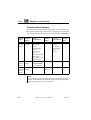
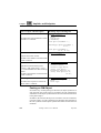
Transformation Scheme
The table below presents all the possible object type combinations for
the copied and pasted object in the Paste As operation. The preselected
choice shown when the Paste As dialog is opened is shown in bold face.
Copied
object
Paste As
in OM
Editor
Paste As
in SDL Editor
Paste As
in MSC
Editor
Paste As
Paste As
in Orgain Text Editor
nizer
Class
(in OM
Editor)
Class
Object
System Type
Block Type
Block
Process Type
Process
Service Type
Service
Text symbol with
NEWTYPE
Text symbol with
SDL interface
—
C++ class
C struct
IDL Module
IDL interface
ASN.1 sequence
System
Object
(in OM
Editor)
Class
Object
Block instance
Process instance
Service instance
—
—
System
—
Instance
Message
Text fragment MSC
Class
Text
fragment Object
(in Text
Editor)
Note:
Not all object types are possible to Paste As in all situations. Especially in the SDL Editor, the available object types depend on which
diagram type the Paste As is performed in.
452
,um-st1
Telelogic Tau 4.5 User’s Manual
July 2003
The Paste As Command
Transformation Details
The details of the specific object transformations are described in the
following subsections. Please refer to the above table to see which tools
that support a particular object transformation.
Some general transformation details are:
•
The name of a copied symbol can be empty. When pasted as an SDL
diagram, the name “EmptyName” will be used.
•
In SDL diagrams, if the name used for a pasted symbol will be in
conflict with an already existing name, the pasted name will be the
original name suffixed by “_<number>”. For example, if “Name”
already exists for a reference symbol in an SDL diagram, the pasted
symbol will have the name “Name_1”. The number is incremented
until the name is unique.
•
The size of the pasted SDL, MSC and OM symbols are the same as
when a symbol is manually picked from the editor’s symbol menu.
•
The exact layout of generated diagrams may not be depicted correctly in the following illustrations. Only the upper left part of a diagram is shown.
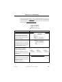
Pasting an OM Class
An OM class may be represented and defined by several class symbols
in the OM diagrams. This is the case if more than one class symbol with
exactly the same class name is found within the OM scope (the diagram
itself or the diagrams in the same Organizer module).
When an OM class is pasted, all class symbols defining the class in the
scope are considered. It is the combined set of attributes and operations in the class symbols that will be used in the transformation to the
pasted object.
In the following descriptions of object transformations, we use the two
class symbols shown in Figure 144 (within the same scope) as a generic
example. Regardless of which class symbol is copied, both class symbols are considered in the transformations.
July 2003
Telelogic Tau 4.5 User’s Manual
,um-st1
453
Chapter
10
Implinks and Endpoints
Figure 144: Two class symbols in the same scope
Note:
Even if there are more than one class symbol in the scope, only the
copied symbol will be linked with the pasted object (if a link is created). Links are not created for the other symbols in the scope.
Paste As object, with description
Resulting objects and diagrams
Class symbol
The pasted class is simply a copy of the
merged class.
Object symbol
The pasted object contains the merged
attributes of the class. The object is
named ‘a’ followed by the class name.
System Type diagram
Block Type diagram
Block diagram
In these cases, only a reference symbol is
created, not any contents of the diagram.
454
,um-st1
Telelogic Tau 4.5 User’s Manual
July 2003
The Paste As Command
Paste As object, with description
Resulting objects and diagrams
Process Type diagram
Service Type diagram
A reference symbol is created, as well as
the referenced diagram with some contents.
The keyword “{async}” after an operation means that it will be transformed using a signal interface. A gate named ‘G’
followed by the class name, and a signal
list named “SL” followed by the class
name, is added.
The keyword “{sync}” after an operation means that it will be transformed using an RPC interface. The procedure diagram is created with an additional heading symbol containing FPAR and
RETURNS statements for parameters
and return type.
If no keyword is given, signal interface
is the default for operations without return value, and RPC interface is the default for operations with return value.
NOTE: Text symbols containing the
declarations of the signal list and the remote procedures must be created by a
separate Paste As operation, usually in a
diagram at a higher level. See “Text
symbol with SDL interface” on page 456
(below).
July 2003
Telelogic Tau 4.5 User’s Manual
,um-st1
455
Chapter
10
Implinks and Endpoints
Paste As object, with description
Resulting objects and diagrams
Process diagram
Service diagram
The same transformation as for process
type and service type, but the signal interface is added as a SIGNALSET statement in the additional heading symbol.
NOTE: Text symbols containing the
declarations of the signal list and the remote procedures must be created by a
separate Paste As operation, usually in a
diagram at a higher level. See “Text
symbol with SDL interface” on page 456
(below).
Text symbol with SDL interface
A text symbol is added, containing declarations for the signal list and/or remote
procedures, as described for process type
and service type above.
456
,um-st1
Telelogic Tau 4.5 User’s Manual
July 2003
The Paste As Command
Paste As object, with description
Resulting objects and diagrams
Text symbol with NEWTYPE
A text symbol is added, containing a
NEWTYPE definition. Operator diagrams are added for all operations, with
additional heading symbols containing
FPAR and RETURNS statements for parameters and return type.
If an operation does not have parameters,
a parameter is inserted with the class
name as type. The class name is also
used as return type if an operation does
not specify any.
System diagram
In the Organizer, the system diagram is
added in the same way as for the Add
New operation, i.e. the diagram is added
as a new root diagram at the current selection. The diagram is also opened in
the SDL Editor.
C++ class definition
The link to the class definition is inserted
inside a C++ comment.
// class ClassName
class ClassName {
public:
void Oper1();
ReturnType Oper2(T1 P1);
void Oper3(T1 P1, T2 P2);
private:
Attr1;
Type Attr2;
};
July 2003
Telelogic Tau 4.5 User’s Manual
,um-st1
457
Chapter
10
Implinks and Endpoints
Paste As object, with description
Resulting objects and diagrams
C struct definition
/* struct ClassName */
typedef struct {
Attr1;
The link to the struct definition is insertType Attr2;
} ClassName;
ed inside a C comment.
void Oper1(ClassName *);
ReturnType Oper2(ClassName *,
T1 P1);
void Oper3(ClassName *,
T1 P1, T2 P2);
IDL module
Only the class name is used.
The link to the module is inserted inside
an IDL comment.
IDL interface
// module ClassName
module ClassName {
};
// interface ClassName
interface ClassName {
attribute Attr1;
attribute Type Attr2;
Operations marked with keyword
“{async}” will get the string oneway
oneway void Oper1();
void inserted before the name of the opReturnType Oper2(T1 P1);
eration.
oneway void Oper3(T1 P1,
T2 P2);
The link to the interface is inserted inside
};
an IDL comment.
ASN.1 sequence
The link to the sequence is inserted inside an ASN.1 comment.
// ClassName SEQUENCE
ClassName ::= SEQUENCE {
Attr1,
Attr2 Type
}
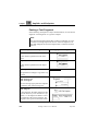
Pasting an OM Object
In a similar way as when pasting an OM class, all object symbols of exactly the same class in the scope are considered. It is the combined set
of attributes in the object symbols that will be used in the transformation
to the pasted object.
In addition, the class that the object is an instance of is also considered,
if it exists. That is, it is the combined set of attributes and operations in
the class symbols and the objects symbols that will be used in the transformation.
458
,um-st1
Telelogic Tau 4.5 User’s Manual
July 2003
The Paste As Command
In the following descriptions of object transformations, we use the object symbol shown in Figure 145 as a generic example. In addition, the
object is assumed to be located in the same scope as the two class symbols shown in Figure 144 on page 454.
Figure 145: An Object symbol
Paste As object, with description Resulting objects and diagrams
Class symbol
The pasted class uses the class
name, attributes and operations
from the copied object and the object’s class symbols.
Object symbol
The pasted object uses the name
and attributes from the copied object and the object’s class symbols,
but without attribute values.
Block instance diagram
Process instance diagram
Service instance diagram
The pasted diagram becomes an
instance diagram (indicated in the
Organizer).
See “System diagram” on page 457.
System diagram
Works in the same way as when
pasting an OM class. The name of
the diagram will be
“Object : ClassName”.
July 2003
Telelogic Tau 4.5 User’s Manual
,um-st1
459
Chapter
10
Implinks and Endpoints
Pasting a Text Fragment
In the following descriptions of object transformations, we use the text
fragment “Text Fragment” as a generic example.
Note:
The copied text fragment must either contain no endpoints, or exactly match an existing endpoint in the text. If the text fragment contains both endpoint text and non-endpoint text, it cannot be used for
Paste As.
Paste As object, with description
Resulting objects and diagrams
Class symbol
Syntax check is performed on the class
name.
Object symbol
Syntax check is performed on the object
name.
Text fragment
Text Fragment
The pasted text is simply a copy of the copied text.
MSC instance
MSC message out
MSC message in
The two message types place the endpoint
at different ends of the message line.
MSC diagram
In the Organizer, the MSC diagram is added in the same way as for the Add New operation, i.e. the diagram is added as a new
root diagram at the current selection. The
diagram is also opened in the MSC Editor.
460
,um-st1
Telelogic Tau 4.5 User’s Manual
July 2003
Other Edit Commands
Other Edit Commands
Some of the commands in the Edit menu in the editors are affected when
operating on objects that have endpoints with connected links.
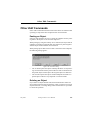
Pasting an Object
If objects with endpoints are cut or copied, the endpoints and any existing links to the objects are saved in the clipboard.
When pasting (by using the ordinary Paste command) an object with an
endpoint, but without connected links, the endpoint is pasted together
with the object without further user interaction.
When pasting objects that also have links connected to their endpoints,
the following dialog appears:
Figure 146: The Paste dialog
•
The Yes button pastes the objects and keeps the links. An object having connected links will be pasted with new links created between
the pasted object and the objects the original object was linked to.
•
The No button pastes the objects without endpoints and links. No
pasted objects will have any endpoints or connected links.
Deleting an Object
If you delete an object that has links, the link information will be destroyed and cannot be restored. Therefore, when you want to cut or clear
objects with links, a warning dialog will be issued where it is possible
to cancel the operation.
July 2003
Telelogic Tau 4.5 User’s Manual
,um-st1
461
Chapter
10
Implinks and Endpoints
The Link Manager
The Link Manager manages endpoints and links in a system. The Link
Manager handles the link file, containing information about the endpoints and links in a system. The syntax of the link file is described in
“The Link File” on page 485.
For an overview of link concepts, see “Link Concepts and Overview”
on page 428. In addition, the following concepts are used in the Link
Manager:
•
Entity
A collection of endpoints with the same type and name in the same
scope is called an entity. The scope is defined as the file the endpoint
resides in. If the file is in an Organizer module, the scope is the module.
•
Cardinality
The number of links associated with an endpoint, i.e. the total number of links going to and from the endpoint.
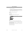
Link Manager Window
The Link Manager’s window is shown in Figure 147. The window title
contains the name of the loaded link file, and is appended by an asterisk
‘*’ if the link file is modified.
In the window, the endpoints in the system are presented graphically using icons. The links between the endpoints are represented as lines between them, with an arrow stating the direction of the link. The Link
Manager can present different views of the endpoint/link information;
these are described in “Presentation Views and Link Trees” on page
464.
462
,um-st1
Telelogic Tau 4.5 User’s Manual
July 2003
The Link Manager
Figure 147: The Link Manager window
At the top of the drawing area, the name of the current link file is presented under a “Information from” heading. If several link files are
merged, they are all listed here until the next Save operation. If a local
link file is used (see “Local Link File” on page 429), both the master
link file (read only) and the local link file are listed.
If the information in the Link Manager is not yet saved, “on-line editing” will be displayed to indicate that endpoints have been created in an
editor or in the Organizer.
The main part of the drawing area displays all endpoints and links as
link trees. Every endpoint is a root node, and the associated links and
endpoints are added to that root. Link trees can be collapsed, and endpoints and links can be hidden.
Below the link trees, some statistics are presented under a “Statistics”
heading. The number of endpoints and links is displayed, including the
number of hidden endpoints and links, as in the following example:
Statistics:
10 endpoints (2 not shown)
July 2003
Telelogic Tau 4.5 User’s Manual
,um-st1
463
Chapter
10
Implinks and Endpoints
4 links (1 not shown)
Endpoint Icons
The Link Manager uses the same icons for endpoints as the Entity Dictionary. See “Entity Icons” on page 436 for more information.
The icons can have different layouts indicating the state of the associated endpoint:
Normal
The normal state of the icon. Information is not modified.
Invalid
An endpoint is marked invalid if, after a Check Endpoints operation, it
is not present in the document where it was supposed to be.
Dirty
The endpoint is modified or newly created from an editor, but the link
file is not yet saved.
Dashed
The endpoint is already displayed on a higher level in the same tree, or
it belongs to the TO group after a Consistency Check.
The endpoints are added as new root symbols below the last link tree as
they are created. The order of the icons can be changed by using the
quick buttons Move Down and Move Up.
Presentation Views and Link Trees
The Link Manager has two main methods of displaying endpoints, using an Endpoint view or an Entity view. There is also a Consistency
view, used for presenting the results after a consistency check has been
performed (see “Consistency Check” on page 476). When there is no selection in the drawing area, the name of the currently displayed view is
shown in the status bar.
In Endpoint view, a link tree looks like this:
464
,um-st1
Telelogic Tau 4.5 User’s Manual
July 2003
The Link Manager
Figure 148: Link tree in Endpoint view
To the right of each endpoint icon, the following information identifying the endpoint is displayed (depending on the options set in Options
> Endpoint):
•
The endpoint type, i.e. the type of the endpoint object.
•
The name of the endpoint, in a plain type face. For endpoints containing a name, such as diagram symbols, this name is listed. For
other symbols and text fragments, the first 25 characters are shown.
•
The file the endpoint resides in. The file name is shown with or
without its absolute path depending on the setting in the Organizer.
•
The link cardinality; the number of “out” links followed by the number of “in” links.
•
The number of hidden links, if any, within parenthesis.
For each link in a link tree, the name of the link is displayed above the
endpoint information, in bold face. The link name display can be
switched on or off by the menu choice Options > Link.
The link comment, if it is used, is shown directly below the link name,
in italics. The comment display can be switched on or off by the menu
choice Options > Link.
In Entity view, all endpoints representing the same entity are collected
into one symbol, and the number of endpoints represented by that entity
is presented to the right of the name of the entity, preceded by an asterisk ‘*’. Also, instead of displaying the filename the endpoint resides in,
the scope the entity resides in is displayed. The scope is either a filename or a module. An example of an endpoint in Entity view:
Figure 149: An entity in Entity view
July 2003
Telelogic Tau 4.5 User’s Manual
,um-st1
465
Chapter
10
Implinks and Endpoints
Link Manager operations on endpoints also apply to entities. If there is
a difference in the behavior of a menu choice depending on the view,
this will be pointed out in the descriptions of the operations.
Double-Clicks
Double-clicking on an icon invokes the menu choice Show in Editor. In
Entity view, if the selected entity corresponds to several endpoints, they
will be selected one at a time for each double-click.
Menu Bar
This section describes the menu bar of the Link Manager window and
all the available menu choices.
The menu bar contains the following menus:
•
•
•
•
•
File Menu
Edit Menu
View Menu
Tools Menu
Help Menu
(see “Help Menu” on page 15 in chapter 1, User Interface and Basic
Operations).
File Menu
The File menu contains the following menu choices:
•
•
•
•
•
•
•
New
Open
Merge
Save
Save As
Print
Close
The menu choices are described in “File Menu” on page 8 in chapter 1,
User Interface and Basic Operations, except Print, which is described
in “The Print Dialogs in the SDL Suite and in the Organizer” on page
308 in chapter 5, Printing Documents and Diagrams, and Merge, which
is described below.
466
,um-st1
Telelogic Tau 4.5 User’s Manual
July 2003
The Link Manager
Merge
This menu choice opens an existing link file, and merges the contents
of that file with the information already in the Link Manager. It works
in a similar way to Open, but keeps the current endpoint and link information.
If two links are equal (i.e. they have the same source and destination
endpoints and the same name) but they have different link comments,
the new comment will consist of the old comments separated by a newline character.
Edit Menu
The Edit menu contains the following menu choices:
•
•
•
•
•
Highlight Endpoint
Replace Endpoint
Create Link
Link Details
Clear Link.
Highlight Endpoint
This menu choice highlights an endpoint. Highlighting an endpoint is
the first step to replace an endpoint or create a link. The highlighting is
presented as a frame around the highlighted endpoint.
The first time this menu choice is used, the selected endpoint will be
highlighted. The second time this menu choice is used for the same endpoint the highlighting will be removed. There is at most one highlighted
endpoint. If another endpoint already was highlighted, the highlighting
is moved to the selected endpoint.
Replace Endpoint
This menu choice replaces an endpoint with another endpoint. This operation is useful if an endpoint has become Invalid and the user has
found a replacement endpoint that all links should be moved to.
One endpoint is defined with the Highlight Endpoint menu choice, the
other endpoint is defined by the selection.
All links going to or from the replaced endpoint will be updated to go
to or from the other endpoint instead. If the replaced endpoint was invalid, the user is given the option to delete the replaced endpoint.
July 2003
Telelogic Tau 4.5 User’s Manual
,um-st1
467
Chapter
10
Implinks and Endpoints
The following dialog appears:
Figure 150: The Replace Endpoint dialog
•
•
Replace highlighted <endpoint>
Replace selected <endpoint>
Depending on the setting of the radio button, either the highlighted
or the selected endpoint will be replaced.
•
Move links going to/from
These options are used to select if links going to the replaced endpoint, or links going from the replaced endpoint, will be moved.
•
Delete replaced and invalid endpoint
If the endpoint to be replaced is invalid, it can optionally be deleted.
If any links going to the deleted endpoint are not moved, they will
also be deleted.
Create Link
This menu choice creates a link between the highlighted endpoint and
the selected endpoint.
One endpoint is defined with the Highlight Endpoint menu choice, the
other is defined by the selection.
The Create Link dialog appears, see Figure 139 on page 443.
468
,um-st1
Telelogic Tau 4.5 User’s Manual
July 2003
The Link Manager
Link Details
This menu choice displays information about the link above the selected
endpoint; the name, the comment, and the direction of the link. All these
attributes can be edited.
The following dialog appears:
Figure 151: The Link Details dialog
The dialog works in the same way as the Create Link dialog, see
Figure 139 on page 443.
Clear Link
This menu choice clears (deletes) the link above the selected endpoint.
Only the link will be cleared, not the associated endpoints. You will be
asked to confirm or cancel the deletion.
July 2003
Telelogic Tau 4.5 User’s Manual
,um-st1
469
Chapter
10
Implinks and Endpoints
View Menu
The View menu contains the following menu choices:
•
•
•
•
•
•
•
•
Expand
Expand Substructure
Collapse
Options > Window
Options > Link
Options > Endpoint
Filter
Set Scale.
Expand
This menu choice expands the endpoint structure tree one level down
for the selected endpoint. If any endpoints one level down are hidden,
they will still be hidden after this operation. (Use the Filter menu choice
to show or hide endpoints).
The menu choice is dimmed if:
•
•
•
No endpoint is selected
The selected icon is a leaf (no children icons)
The selected icon is already expanded
Expand Substructure
This menu choice expands the endpoint structure tree the whole way
down for the selected endpoint. If there is no selection, all endpoint trees
will be expanded.
Collapse
This menu choice collapses the selected endpoint, i.e. the sub symbols
are not shown after this operation. A collapsed endpoint has a small triangle drawn below the icon to indicate that it is collapsed. If there is no
selection, everything will be collapsed.
470
,um-st1
Telelogic Tau 4.5 User’s Manual
July 2003
The Link Manager
Options > Window
This menu choice sets options for controlling the appearance of the Link
Manager window.
The following dialog appears:
Figure 152: The Window Options dialog
•
Show: Tool Bar
•
Show: Status Bar
These options control whether the tool bar and the status bar should
be displayed or not.
•
Show: endpoints/entities
By using this radio button, Endpoint or Entity view is selected (see
“Presentation Views and Link Trees” on page 464).
July 2003
Telelogic Tau 4.5 User’s Manual
,um-st1
471
Chapter
10
Implinks and Endpoints
Options > Link
This menu choice sets options for controlling the appearance of links in
the drawing area.
The following dialog appears:
Figure 153: The Link Options dialog
•
Show: Name
Show/hide the name of all links.
•
Show: Comment
Show/hide the comment for all links.
•
Links: reverse first/forward first
This setting controls whether links going to a root endpoint (reverse
first) or links going from a root endpoint (forward first) will be displayed first in the link trees.
472
,um-st1
Telelogic Tau 4.5 User’s Manual
July 2003
The Link Manager
Options > Endpoint
This menu choice sets options for controlling the appearance of endpoints in the drawing area.
The following dialog appears:
Figure 154: The Endpoint Options dialog
•
Show: Type
Show/hide the type of the endpoints.
•
Show: File
Show/hide the file name (or module) of the endpoints.
•
Show: Cardinality
Show/hide the cardinality, i.e. the number of links going to and from
an endpoint.
•
Show: Not shown links
Show/hide the number of hidden links going to and from an endpoint.
July 2003
Telelogic Tau 4.5 User’s Manual
,um-st1
473
Chapter
10
Implinks and Endpoints
Filter
This menu choice is used for filtering out endpoints and/or links which
will not be shown. The filter is set in a modeless dialog, i.e. the Link
Manager continues working without waiting for the dialog to be closed.
If an endpoint is hidden, all links associated to it will be hidden. If a link
is hidden, the endpoints associated to it will still be visible.
The following dialog appears:
Figure 155: The Filter dialog
•
Filter settings for links/endpoints/documents
By using this option menu, filtering can be done on endpoint types,
link names, and document file names. All filters are active simultaneously, i.e. for the filter to take effect, all three filter conditions
must be true.
The multiple-selection list in the dialog contains all link names,
endpoint types or file names in the loaded link file, depending on the
current setting of the option menu. By default, nothing is selected.
•
Select <type of filter> that should be hidden/shown
Depending on this option menu choice, the selected links/endpoints/documents will either be hidden or shown.
474
,um-st1
Telelogic Tau 4.5 User’s Manual
July 2003
The Link Manager
•
Hide not linked endpoints
If this option is set, all endpoints which are not linked will be hidden. This option is dimmed if filtering is not done on endpoint types.
•
Pressing Default will set all the lists to their default values, but the
filter is not applied until Apply is pressed.
Set Scale
Issues a dialog where the scale may be set.
Tools Menu
The Tools menu contains the following menu choices:
•
Show Organizer
(see “Show Organizer” on page 15 in chapter 1, User Interface and
Basic Operations)
•
•
•
•
•
Search
Search Again
Consistency Check
Check Endpoints
Show in Editor.
Search
This menu choice searches for a text string in endpoints or links.
The searching is based on ASCII character matching. All texts related
to the endpoints and links are searched, i.e. endpoint types and names,
link names and comments.
The search will start from the selected endpoint, or from the first endpoint if nothing is selected.
The following dialog appears:
July 2003
Telelogic Tau 4.5 User’s Manual
,um-st1
475
Chapter
10
Implinks and Endpoints
Figure 156: The Search dialog
•
Search for
The text string to search for. If a search already has been done, the
previous search text is used by default.
•
Ignore Case/Consider case
Depending on the radio button setting, the search will either be case
sensitive or not.
Search Again
This menu choice searches again for the same text string as the last performed search.
The menu choice is dimmed if a search has not yet been done.
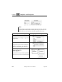
Consistency Check
This menu choice is used for checking the consistency between a group
of documents (the FROM group) and another group of documents (the
TO group).
In Entity view, there are two types of consistency checks to choose
from. The following dialog appears:
Figure 157: The Link Check/Entity Match dialog
476
,um-st1
Telelogic Tau 4.5 User’s Manual
July 2003
The Link Manager
•
Link check
Check that all endpoints/entities in the FROM group are linked with
at least one endpoint/entity in the TO group.
•
Entity match
Check that all entities (not endpoints) in the FROM group has
matching entities (not endpoints) in the TO group.
The above dialog is not opened in Endpoint view, in which case a link
check always is performed.
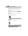
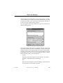
First, the documents in the FROM group must be selected. The following dialog appears:
Figure 158: Selecting the FROM group
In the list of Organizer documents and modules, one or several documents must be selected. Selecting/deselecting a module will select/deselect all the documents in that module. Selecting/deselecting an SDL
system will select/deselect all documents in that system. Individual documents in the module/system can then be selected/deselected without
affecting the other documents.
When all FROM documents are selected, the Continue button is used to
close the dialog and continue to the next dialog.
Then, the documents in the TO group must be selected. The following
dialog appears:
July 2003
Telelogic Tau 4.5 User’s Manual
,um-st1
477
Chapter
10
Implinks and Endpoints
Figure 159: Selecting the TO group
The list of Organizer documents and modules works in the same way as
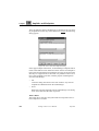
when selecting the FROM documents. When all TO documents are selected, the Check button is used to close the dialog and start the consistency check operation.
The result of the consistency check is presented as a special view in the
drawing area. This Consistency view only shows endpoints/entities
from the two defined groups of documents. Endpoints/entities from the
FROM group are shown in the normal way, and endpoints/entities from
the TO group are shown as Dashed symbols.
The Consistency view is only showing links going from the FROM
group of entities/endpoints to the TO group. After a link check, the links
shown are the “real” links, as defined by the user. After an entity match,
the links shown are only temporary links created by the Link Manager
to indicate matching entities. The link name for such links are “Matching” and the link comment is “(Temporary link)”.
By selecting Endpoint or Entity view in Options > Window, the view
will return to the selected normal view. By pressing the quick button
Show Endpoints or Entities, the view will return to the previously used
view.
Check Endpoints
This menu choice checks if there are endpoints in the Organizer or in
the editors that do not exist in the Link Manager, or if there are invalid
endpoints in the Link Manager. This menu choice could be used to remove any inconsistencies between the document endpoints in the system and the information in the Link Manager.
478
,um-st1
Telelogic Tau 4.5 User’s Manual
July 2003
The Link Manager
The information in the saved files is used for the checking, so if there
are unsaved changes in an editor, these will not be taken into account in
the checking. If there are any documents in the Organizer which have
not been saved, the following dialog appears:
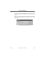
First, the Organizer and all documents in the system are checked. The
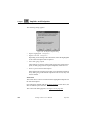
following dialog appears:
Figure 160: The first Check Endpoints dialog
In the upper multiple selection list, all endpoints that were found in the
Organizer, but do not exist in the Link Manager, are listed. In the lower
multiple selection list, all endpoints that were found in the documents
belonging to the system, but do not exist in the Link Manager, are listed.
It is possible to select one or more of the endpoints in the lists, with the
purpose of adding them to the Link Manager.
•
Continue
Closes the dialog and continues to the next dialog. Any selected
endpoints are not added to the Link Manager.
•
Add
Adds the selected endpoints to the Link Manager. The dialog is not
closed until the Continue button is pressed.
July 2003
Telelogic Tau 4.5 User’s Manual
,um-st1
479
Chapter
10
Implinks and Endpoints
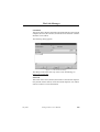
Then, the endpoints in the Link Manager are checked. If any non-existing endpoints are found, they will be marked as Invalid. The following
dialog appears:
Figure 161: The second Check Endpoints dialog
In the upper multiple selection list, all Link Manager endpoints which
reside in files that have been deleted are listed. In the lower multiple selection list, all Link Manager endpoints that no longer are present in the
files they are supposed to be in are listed. It is possible to select one or
more of the endpoints in the lists, with the purpose of deleting them
from the Link Manager.
•
OK
Closes the dialog and returns to the main window. Any selected
endpoints are not deleted from the Link Manager.
•
Delete
Deletes the selected endpoints from the Link Manager. The dialog
is not closed until the OK button is pressed.
Show in Editor
This menu choice will show the symbol which corresponds to the selected endpoint in an editor.
480
,um-st1
Telelogic Tau 4.5 User’s Manual
July 2003
The Link Manager
In Entity view, each entity can represent more than one endpoint. In that
case, the menu choice will be replaced by Show 1 in Editor, Show 2 in
Editor, etc.
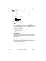
If there are more than nine endpoints, the menu choice Show in Editor
will invoke the following dialog, where it is possible to select the appropriate endpoint:
Figure 162: The Show in Editor dialog
July 2003
Telelogic Tau 4.5 User’s Manual
,um-st1
481
Chapter
10
Implinks and Endpoints
Popup Menus
There are two popup menus available in the Link Manager:
On Endpoints
Highlight Endpoint
“Highlight Endpoint” on page 467
Replace Endpoint
“Replace Endpoint” on page 467
Create Link
“Create Link” on page 468
Link Details
“Link Details” on page 469
Clear Link
“Clear Link” on page 469
Expand
“Expand” on page 470
Expand Substructure “Expand Substructure” on page 470
Collapse
“Collapse” on page 470
Show in Editor
“Show in Editor” on page 480
On the Background
Consistency Check
“Consistency Check” on page 476
Check Endpoints
“Check Endpoints” on page 478
Expand Substructure “Expand Substructure” on page 470
482
Collapse
“Collapse” on page 470
Options > Window
“Options > Window” on page 471
Options > Link
“Options > Link” on page 472
Options > Endpoint
“Options > Endpoint” on page 473
Filter
“Filter” on page 474
Search
“Search” on page 475
Search Again
“Search Again” on page 476
Show Organizer
“Show Organizer” on page 15 in chapter 1,
User Interface and Basic Operations
,um-st1
Telelogic Tau 4.5 User’s Manual
July 2003
The Link Manager
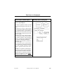
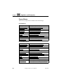
Keyboard Accelerators
In addition to the standard keyboard accelerators, described in “Keyboard Accelerators” on page 35 in chapter 1, User Interface and Basic
Operations, the following accelerators can be used in the Link Manager:
July 2003
Accelerator
Reference to corresponding command or
quick button
Ctrl+E
“Show in Editor” on page 480
Ctrl+1
“Show Organizer” on page 15 in chapter 1, User
Interface and Basic Operations
Del
“Clear Link” on page 469
Arrow up
Select the endpoint one step up (move the selection)
Shift+arrow up
“Move Up” on page 484
Arrow down
Select the endpoint one step down (move the selection)
Shift+arrow
down
“Move Down” on page 484
Telelogic Tau 4.5 User’s Manual
,um-st1
483
Chapter
10
Implinks and Endpoints
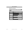
Quick Buttons
Except for some of the general Telelogic Tau quick buttons (see “General Quick-Buttons” on page 24 in chapter 1, User Interface and Basic
Operations) the following quick buttons are included the Link Manager.
Show Endpoints or Entities
Switches between the Endpoint and the Entity views; see “Options >
Window” on page 471.
Consistency Check
Performs a consistency check operation; see “Consistency Check” on
page 476.
Highlight Endpoint
Highlights the selected endpoint; see “Highlight Endpoint” on page
467.
Create Link
Creates a link between the highlighted and the selected endpoint; see
“Create Link” on page 468.
Switch Link Direction
Changes the order of the links going to or from the (root) endpoint; see
“Options > Link” on page 472.
Show or Hide Unused Endpoints
Toggles between showing and hiding endpoints that are not linked; see
“Filter” on page 474.
Move Down
Moves the selected (root) endpoint one step down in the Link Manager
view.
Move Up
Moves the selected (root) endpoint one step up in the Link Manager
view.
484
,um-st1
Telelogic Tau 4.5 User’s Manual
July 2003
The Link File
The Link File
The Link Manager maintains a link file that contains a list of all endpoints and links in the system. The link file is a line-oriented, humanreadable text file, with the default file name extension .sli.
The file has the following format:
<link file> ::= <endpoints> <links> $
<endpoints> ::= [ENDPOINTS] <endpoint>*
<endpoint> ::= <endpoint id> <endpoint format>
<endpoint id> ::= <integer>
A unique integer identifying the endpoint in the link file.
<endpoint format> ::= ‘(’ <format> , <file name>
(, <anchor> | $) ‘)’ <name>
<type>
<format> ::= SDL | OM | MSC | TEXT | WORD
<file name> ::= <string>
Name of the document file.
<anchor> ::= <string>
A unique string identifying the endpoint in the document. If the endpoint refers to the whole file, i.e. the endpoint is created in the Organizer, the anchor is set to an empty string (“”).
<name> ::= <quoted string>
The name of the endpoint, in quotes.
<type> ::= <integer>
Type of document.
<links> ::= [LINKS] <link>*
<link> ::= <endpoint id> <endpoint id> <link name>
<link comment>
<link name> ::= <quoted string>
The name of the link, in quotes.
<link comment> ::= <quoted string>
The link comment, in quotes.
July 2003
Telelogic Tau 4.5 User’s Manual
,um-st1
485
Chapter
10
486
,um-st1
Implinks and Endpoints
Telelogic Tau 4.5 User’s Manual
July 2003