1
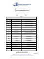
Argon Series Hardware User Manual
Version: 1.51
21 December 2012
Contents
I. Introduction .................................................................................... 2
II. Device Layout ............................................................................... 4
III. Setup............................................................................................ 5
IV. SMS Commands.......................................................................... 9
V. Setup Examples.......................................................................... 14
VI. Installation Considerations ......................................................... 17
VII. Safety Recommendations ......................................................... 19
VIII. Conformity Assessment ........................................................... 20
Appendix A...................................................................................... 21
Appendix B...................................................................................... 22
Appendix C...................................................................................... 23
Page 1 of 24
Bramble Orchard, Folly Lane North, Farnham, Surrey, GU9 0HX
Tel: 01252 351030. Fax: 01252 323492. Website: www.anvilleinstruments.com
I.Introduction
The Argon alert and monitoring solution allows the user to pre-set a temperature range
and receive an alert (via SMS, phone call, email or server script) if the current
temperature exceeds the pre-set range. It is also possible to read the current
temperature.
An email/http log is also supported. Temperature logs can be recorded at predetermined
intervals and sent to a valid email address when required.
Page 2 of 24
Bramble Orchard, Folly Lane North, Farnham, Surrey, GU9 0HX
Tel: 01252 351030. Fax: 01252 323492. Website: www.anvilleinstruments.com
The Argon software can be controlled in two ways:
1: Via the use of SMS command messages. These are standard text messages sent
from a mobile phone which are formatted in a specific way to configure the software (i.e.
change GPRS settings)
2: Via a Windows compatible based configuration tool (USB to serial driver and Microsoft
.NET framework required – ensure Windows has latest service pack installed on your
computer).
The Argon software is designed to operate with Anville Instruments Ltd 1-wire sensor(s)
in conjunction with the supplied Serial RS232 Proton-1 Temperature adapter.
Functions include:
•
•
•
•
Remote temperature reporting of site equipment
Logging of temperature data in remote locations via email/HTTP post (see note)
Over/under temperature alarm notification via SMS and phone call (DTMF alert
tone), HTTP post alert and email.
Instantaneous temperature reading via status SMS
Note: HTTP post support allows integration of logs and alerts from the unit to existing
server side reporting / management applications.
Features:
Global Quad Band GSM/GPRS Engine
External GSM Antenna for increased performance
Specifications:
Frequency Band: 850/900/1800/1900MHz
Dimensions: 93 mm x 67 mm x 28 mm
Weight: 385g (excluding PSU)
Supply Voltage: 5V-60V
Modem Temp Limits: -20°C ~ +70°C
Sensor Temp Limits: -30°C ~ +125°C
Page 3 of 24
Bramble Orchard, Folly Lane North, Farnham, Surrey, GU9 0HX
Tel: 01252 351030. Fax: 01252 323492. Website: www.anvilleinstruments.com
II.Device Layout
Front View
1.
2.
3.
4.
RS232 Temperature Sensor Attachment.
Mini-USB – not used for Argon100/200/500 GSM temperature series.
LED Status Lights
SIM Card Holder
Rear View
5. Antenna Connector (SMA Female)
6. Power Connector (Supply Voltage:5V-60V)
Page 4 of 24
Bramble Orchard, Folly Lane North, Farnham, Surrey, GU9 0HX
Tel: 01252 351030. Fax: 01252 323492. Website: www.anvilleinstruments.com
III.Setup
Insert SIM Card
With the Argon RS232 connector pointing down insert the SIM card this way
See quick start guide (Appendix A)
Power Connection
Use the power supply provided for powering the Argon from standard wall socket.
For power connection see quick start guide (Appendix A)
See Appendix B for use of alternative power supply
Antenna Connection
See quick start guide (Appendix A)
Antenna Technical Information (Appendix C)
LED Configuration and status
Page 5 of 24
Bramble Orchard, Folly Lane North, Farnham, Surrey, GU9 0HX
Tel: 01252 351030. Fax: 01252 323492. Website: www.anvilleinstruments.com
The following table shows the meanings for the LED status and the different states that they represent.
LED Colour
LED Status
Description
Red
Flash once per second
Searching for GSM network
Red
Flash once every 3 seconds
Registered to GSM network
Red
Permanently On
Ringing OR call in progress
Red
Permanently Off
Terminal Off
Blue
Permanently Off
Attempting to connect to GPRS network
Blue
Permanently On
Connected to GPRS network
Green
Permanently Off
Attempting to connect to server
Green
Permanently On
Connected to server
Green
1 Flash
Main loop processed
Green
2 Flashes
Read Temperature(s)
Green
3 Flashes
Alert Triggered
Green
4 Flashes
Log Triggered
Green
5 Flashes
Notify Successful
Green
11 Flashes
No Temperature(s) Read
Set-up Proton-1 Sensor Adapter
Page 6 of 24
Bramble Orchard, Folly Lane North, Farnham, Surrey, GU9 0HX
Tel: 01252 351030. Fax: 01252 323492. Website: www.anvilleinstruments.com
ARGON 100 Set-up
1. Connect the proton-1 adapter to the RS232 connection on the Argon unit.
2. Power off the Argon, wait 8-10 seconds and power up the Argon.
3. The green status light on the Proton-1 will now rapidly blink to indicate it’s in
programming mode.
4. Connect a temperature probe to the Proton-1.
5. Wait 20 seconds and the light will blink steadily once per second on each
successful temperature read.
ARGON 200 Set-up (for up to 2 sensors)
1. Connect the proton-1 adapter to the RS232 connection on the Argon unit.
2. Power off the Argon, wait 8-10 seconds and power up the Argon.
3. The green status light on the Proton-1 will now rapidly blink to indicate it’s in
programming mode.
4. Connect a temperature probe directly to the Proton-1. (do not use hub at this
stage)
5. Wait 10 seconds, once the rapid light stops disconnect the sensor – this will be
sens1 (sensor 1) for configuration.
6. Connect second temperature probe to Argon unit.
7. Wait 20 seconds and the light will blink steadily once per second on each
successful temperature read.
8. Disconnect sensor – this will be sens2 for configuration
9. Attach hub to Argon and connect sensors to hub.
ARGON 500 Set-up (for up to 5 sensors)
1. Connect the proton-1 adapter to the RS232 connection on the Argon unit.
2. Power off the Argon, wait 8-10 seconds and power up the Argon.
3. The green status light on the Proton-1 will now rapidly blink to indicate it’s in
programming mode.
4. Connect a temperature probe directly to the Proton-1. (do not use hub at this
stage)
5. Wait 10 seconds, once the rapid light stops disconnect the sensor – this will be
sens1 (sensor 1) for configuration.
6. Connect second temperature probe to Argon unit.
7. Wait 10 seconds, once the rapid light stops disconnect the sensor – this will be
sens2 (sensor 2) for configuration.
8. Repeat steps 6 & 7 for additional sensor(s)
a. Note: You do not have to use all 5 sensors.
b. Note: On last sensor go to step 9.
9. Wait 20 seconds and the light will blink steadily once per second on each
successful temperature read.
10. Disconnect sensor.
11. Attach hub to Argon and connect sensors to hub.
Steady State Operation
Page 7 of 24
Bramble Orchard, Folly Lane North, Farnham, Surrey, GU9 0HX
Tel: 01252 351030. Fax: 01252 323492. Website: www.anvilleinstruments.com
Once the power up initialisation has been completed, the unit will go into the steady
state operation mode. In this mode it will cycle through all the attached temperature
sensors that have been identified and stored in non-volatile memory. The time taken to
cycle through and read all the sensors depends on how many sensors are attached.
On reading a sensor the green status LED on the proton-1 will blink to indicate that a
temperature measurement has been taken.
If new temperature sensors are attached during run time operation, these new sensors
will be ignored. Sensors can only be detected as part of the power up process. If sensors
are removed, or some event prevents them from being read, this will be detected as an
error condition. In error, the sensor will report back a value of -999.9 C.
Add or Remove Sensors.
To add or remove sensors at a later date the Proton-1 to needs to be put in to
programming mode again.
1. Disconnect all sensors or hubs from the Proton-1
2. Power off the Argon, wait 8-10 seconds and power up the Argon.
3. The green status light on the Proton-1 will now rapidly blink to indicate it’s in
programming mode.
4. Now follow setup procedure above for all sensors.
a. Note: All sensors must be reprogramed.
Page 8 of 24
Bramble Orchard, Folly Lane North, Farnham, Surrey, GU9 0HX
Tel: 01252 351030. Fax: 01252 323492. Website: www.anvilleinstruments.com
IV.SMS Commands
The Argon software may be controlled via the use of SMS Command messages. These
are standard text messages sent via a mobile phone which are formatted in a specific
way to configure the Argon (i.e. change GPRS settings). For security reasons all
commands start with a password, to ensure that your Argon’s configuration is only set by
authorised personnel.
The default password is connect.
To test the Argon is functioning correctly send an SMS command to the Argon SIM
phone number from a mobile phone and type the message connect status This will
Retrieve the current temperature readings and send the data via SMS to the number this
originated the request.
The Argon SMS command set comprises:
SMSPASSWORD
Change the current password. The password is required in all SMS command messages
sent to the unit. The default password is connect. Valid values are 1-12 characters of 09, a-z lowercase only.
Format: [current_password] smspassword [new_password]
Example: connect smspassword banana123
GPRS
GPRS settings are required for email alerts & reporting.
Allows setting of the GPRS APN, username, and password for the SIM card. These are
obtained from the SIM card provider.
Format: [smspassword] gprs [apn] [username] [password]
Example: connect gprs payandgo.o2.co.uk payandgo password
NAME
Sets the name of the Argon unit. This may be used to uniquely identify the Argon unit
when events (alarms / logs) are sent.
Page 9 of 24
Bramble Orchard, Folly Lane North, Farnham, Surrey, GU9 0HX
Tel: 01252 351030. Fax: 01252 323492. Website: www.anvilleinstruments.com
Format: [smspassword] name [name]
Example: connect name Server Room 1
SENSOR
Set sensor_no/min temp/max temp/report type/alias.
a. sensor_no: 1-5
b. Min temp & max temp (sometimes called safe limits) are in Celcius. The format
must be as follows:
a. -/+xxx.x (numbers only)
b. Example: -12.3 C is denoted by -012.3
c. Example: +5.4 C is denoted by +005.4
c. report_type Type: This consists of the following:
a. both = Alert will be sent if temp goes outside safe limits and alert will also
be sent if temp falls back within the safe limits.
b. out = Alert will be sent if the temp goes outside min temp & max temp
settings. No alert will be sent if the temp falls back into the safe limit.
c. in = Alert will be sent if the temp falls inside the min temp and max temp
settings.
d. alias: This allow you to give the sensors a name.
Format: [smspassword] sensor [sensor_no] [reading_min] [reading_max] [report_type]
[alias]
Example 1: connect sensor 1 +020.0 +025.0 out
This will configure sensor1 to have a safe range of 20 C to 25 C and
only send an alert if the temp goes outside these safe limits. No alias set
so sensor will be referred to as sens1 in alerts.
Example 2: connect sensor 1 -001.5 +005.5 out serverroom1
This will configure sensor1 to have a safe range of -1.5 C to 5.5 C and
will send an alert if the temp goes outside these safe limits. The sensor
will be named severroom1 in all alerts.
Example 3: connect sensor 5 +011.5 +050.0 both kitchen
This will configure sensor5 to have a safe range of 11.5 C to 50.0 C and
will send an alert if the temp goes outside these safe limits and a second
alert if the temp falls back into the safe limits. The sensor will be named
kitchen in all alerts.
Page 10 of 24
Bramble Orchard, Folly Lane North, Farnham, Surrey, GU9 0HX
Tel: 01252 351030. Fax: 01252 323492. Website: www.anvilleinstruments.com
STATUS
This will Retrieve the current temperature readings and send the data via SMS to the
number that originated the request.
Format: [smspassword] status
Example 1: connect status
ALERTINTERVAL
This command is designed to send repeated alerts to the alert contact list if the
temperature is in alert status. If this command is not used the Argon will only send one
alert.
Set alert repeat / min alert interval
a. alert_repeat: The intervals (in seconds – 30 to 86400 seconds) at which the
alarm is repeated after sending the first alert. For no repeat alert set to 0.
b. Min_alert_interval: Delay for sending the very first alarm (in seconds – 60 to
86400 seconds) minimum delay is 60 seconds.
Format: [smspassword] alertinterval [alert_repeat] [min_alert_interval]
Example 1: connect alertinterval 300 60
Will send the first alarm 60 seconds after temperature is outside safe
limits and will repeat alarm every 300 seconds (5 minutes)
Example 2: connect alertinterval 0 120
Will send the first alarm 120 seconds after temperature is outside safe
limits and will not send any subsequent repeat alarms
LOGINTERVAL & LOG_SEND
Used for datalogger function to set the interval in seconds for temperature readings to be
saved for reporting via HTTP, or email.
a. log_repeat: Interval in which the temperature is recorded in seconds (30 to 86400
seconds).
b. log_send: Number of temperature readings (1 to 10) after which the log is
emailed.
Page 11 of 24
Bramble Orchard, Folly Lane North, Farnham, Surrey, GU9 0HX
Tel: 01252 351030. Fax: 01252 323492. Website: www.anvilleinstruments.com
Format: [smspassword] loginterval [log_repeat] [log_send]
Example 1: connect loginterval 60 5
Will record the temperature every 60 seconds and then after 5 reads the
Argon will email the log of 5 records.
Example 2: connect loginterval 120 2
Will record the temperature every 120 seconds and then after 2 reads the
Argon will email the log of 2 records.
NOTIFY
Set the Alert or Log to a set medium, i.e. SMS, Email, URL.
a. notify_type: Chooese to program datalog feature or alert/alarm feature.
a. log: where to send the temperature datalog too.
b. alert: where to send the temperature alert too:
b. notify_method: Type of medium used:
a. email: sends log/alert via email
b. url: sends log/alert via url (requires web gateway script running – hosted
by ISP)
c. sms: sends log/alert via SMS
c. slot_identifier: Location of number/url/email to update/change
a. all: allows you to enter a space separated list of entries in one command
entry. For example update 3 SMS numbers in one command would have
3 numbers separated by spaces after the ‘all’ command
b. 1-10: allows you to update one entry directly. For example to change the
entry for location 3 enter 3 after the ‘notify_method’ and the updated
number/url/email to update only that location.
d. email_call_sms_url: The contact information of where the log/alert will go
a. email = valid email address. (supports up to 10 email addresses) After
each email address there must be a space and then the next valid email
address.
b. url = valid url pointer with web page running script to read data.
c. sms = valid mobile number (up to 10 numbers) After each SMS number
there must be a space and then the next valid SMS number.
d. call = valid phone number, alert is dependent on destination number
having CLI – Calling Line Identification. (up to 10 numbers) After each
phone number there must be a space and then the next valid phone
number.
Format: [smspassword] notify [notify_type] [notify_method] [slot_identifier]
[email_call_sms_url]
Page 12 of 24
Bramble Orchard, Folly Lane North, Farnham, Surrey, GU9 0HX
Tel: 01252 351030. Fax: 01252 323492. Website: www.anvilleinstruments.com
Example 1: connect notify log email all [email protected]
[email protected]
Example 2: connect notify log url all http://www.example.com/log/
Example 3: connect notify alert email all [email protected]
[email protected]
Example 4: connect notify alert sms all +441111111111 +442222222222
Example 5: connect notify alert call all +441111111111 +442222222222
Example 6: connect notify alert url all http://www.example.com/alert/
Example 7: connect notify alert url all
Example 8: connect notify alert sms 2 +442222222223
Example 9: connect notify alert sms 1 +441111111112
Example 9: connect notify alert url 2 http://www.example.com/alert2/
Page 13 of 24
Bramble Orchard, Folly Lane North, Farnham, Surrey, GU9 0HX
Tel: 01252 351030. Fax: 01252 323492. Website: www.anvilleinstruments.com
V.Setup Examples
SMS ALERT (NO REPEAT)
Setup a non repeating alert on sensor 1 called kitchen to be sent via SMS to
+447770123456 if the temperature exceeds, and then falls back within the range of 15P
C to 21P C.
connect sensor 1 +015.0 +021.0 both kitchen
connect notify alert sms all +447770123456
Note: When testing alerts by rapidly heating/cooling the sensor please be aware that the
alert interval setting will result in alerts being sent more frequently than every X seconds.
SMS ALERT (REPEATING)
Setup a 300 second repeating SMS alert on sensor 1 called kitchen to be sent via SMS
to +447770111111 if the temperature exceeds, and then falls back within the range of
15P C to 21P C.
connect sensor 1 +015.0 +021.0 both kitchen
connect alertinterval 300 0
connect notify alert sms all +447770111111
Email Alert (Default server SMTP server)
Setup a non repeating alert on sensor 1 called kitchen to be sent via email to
[email protected] if the temperature exceeds, or falls back within the range of 35PC to
49PC using the GPRS APN payandgo.o2.co.uk, GPRS user payandgo, GPRS pass
password
connect gprs payandgo.o2.co.uk payandgo password
connect sensor 1 +035.0 +049.0 both kitchen
connect notify alert email all [email protected]
Page 14 of 24
Bramble Orchard, Folly Lane North, Farnham, Surrey, GU9 0HX
Tel: 01252 351030. Fax: 01252 323492. Website: www.anvilleinstruments.com
HTTP ALERT (MULTIPLE SENSORS)
Setup a non repeating alert on sensor 1 called kitchen, sensor 2 called lounge, sensor 3
called bedroom and sensor 4 called study to be sent to a script running at
http://www.example.com/alert/ if the temperature exceeds 35P C in the kitchen, falls
below 15P C in the lounge or bedroom or falls below 10 P C in the study, using the GPRS
APN payandgo.o2.co.uk, GPRS user payandgo, GPRS pass password.
connect gprs payandgo.o2.co.uk payandgo password
connect alertinterval 0
connect sensor 1 +000.0 +035.0 out kitchen
connect sensor 2 +015.0 +050.0 out lounge
connect sensor 3 +015.0 +050.0 out bedroom
connect sensor 4 +010.0 +050.0 out study
connect notify alert url all http://www.example.com/alert/
If the SMS password is forgotten then it can be reset using the Windows based serial
configuration utility. Please contact us for information on how to perform this task if
required.
Notes
Note 1: SMS timings are approximate and are dependent on the GSM network provider.
SMS messages are not guaranteed to be sent.
Note 2: SMS commands refer to sensor number starting at sensor 1 and ending at
sensor 5.
Note 3: To disable logging/alerting, clear any specified telephone/email/SMS/HTTP URL.
i.e send SMS connect notify alert sms or use software and delete any unwanted
numbers.
Note 4: Setting notify will clear any internally recorded but unsent alerts/logs.
Note 5: Multipart SMS's are not supported for any command messages, your device may
automatically send a multipart message if you go over the SMS 160 character limit.
Note 6: All alerts can be used simultaneously: SMS/CALL/EMAIL
Page 15 of 24
Bramble Orchard, Folly Lane North, Farnham, Surrey, GU9 0HX
Tel: 01252 351030. Fax: 01252 323492. Website: www.anvilleinstruments.com
Setup Considerations
The Argon will respond to all temperature state changes however this may take a
number of seconds for the response to reach the end user. This is due to the software
processing the request and network delay in transmission of the SMS. Note: Network
delays are beyond the control of the Argon.
SMS Confirmation
Software will acknowledge receipt / action of correctly formatted command messages
with a message in the format OK [name of command processed]. Incorrectly formatted
messages will be responded to with ERROR [error message].
Replies are sent to the sending of the original request. The only exception is that
command messages sent with an invalid password will not be responded to.
smspassword must be composed of 0-9, a-z, only and 1-12 characters in length.
sms configuration messages must be within 1 SMS message length, this means that a
maximum of 160 characters can be used to send the configuration message.
configuration error messages will be not be processed if any errors are found. They will
be reported and disregarded.
Page 16 of 24
Bramble Orchard, Folly Lane North, Farnham, Surrey, GU9 0HX
Tel: 01252 351030. Fax: 01252 323492. Website: www.anvilleinstruments.com
VI.Installation Considerations
Environmental conditions: The terminal must be installed so that the environmental
conditions stated such as temperature, humidity and vibration are satisfied. Additionally,
the electrical specifications must not be exceeded.
GSM Signal strength: The terminal/antenna has to be placed in a position that ensures
sufficient GSM signal strength. To improve signal strength, the antenna can be moved to
a more elevated position. Signal strength usually depends on how close the modem is to
GSM base station. You must ensure that the location at which you intend to use the
modem is within the network coverage area. Degradation in signal strength can be the
result of a disturbance from another source, for example an electronic device in the
immediate vicinity.
Tip: Before installing the modem you can use an ordinary mobile telephone to check the
signal strength in each possible installation location. When considering the location for
the modem and antenna placement, you must consider received signal strength as well
as cable length as long cable runs can attenuate the received signal strength.
Network and Subscription: Before your system is used, you must ensure that your
chosen network provides the necessary telecommunication services. Contact your
service provider to obtain the necessary information.
•
•
If you intend to use SMS in the application, ensure this is included in your
subscription.
Consider the choice of the supplementary services such as GPRS, Voice and
CSD.
The Argon is not suitable for military & medical applications, Sequoia Technology Ltd
and all divisions are not liable for any missed or unsent temperature alarms. We
recommend you fully test and simulate alarm situations approval installation of the
Argon.
Power Supply
•
•
Use a high-quality power supply cable with low resistance. This ensures that the
voltages at the connector pins are within the specified range, especially during
the maximum peak current of approximately 2A.
When the unit is powered from a battery or a high current supply, connect a fast
1.25A fuse in line with the positive supply. This protects the power cabling and
terminal from damage.
Installing the Modem
Page 17 of 24
Bramble Orchard, Folly Lane North, Farnham, Surrey, GU9 0HX
Tel: 01252 351030. Fax: 01252 323492. Website: www.anvilleinstruments.com
Before installing the terminal please take into account the amount of additional space
required for the mating connectors and cables that will be used with the terminal in the
application.
•
Where access is restricted, it may be easier to connect all the cables to the
modem prior to securing it in position.
General Precautions
The Argon terminal is a standalone item designed for indoor use only. For use outside it
must be installed in a weatherproof enclosure.
Do not exceed the environmental and electrical limits as specified.
•
•
•
•
•
•
•
Avoid exposing the terminal to lit cigarettes, naked flames or to extreme hot or
cold temperatures.
Never try to dismantle the modem. There are no components inside the modem
that can be serviced by the user. If you attempt to dismantle the modem, you will
invalidate the warranty.
The Argon terminal must not be installed or located where the surface
temperature of the plastic case may exceed 85°C.
All cables connected to the Argon terminal must be secured or clamped,
immediately adjacent to the modem’s connectors, to provide strain relief and to
avoid transmitting excessive vibration to the modem in the installation.
Ensure the power cable to the Argon terminal does not exceed 3 metres.
To protect power supply cables and to meet the fire safety requirements when
the unit is powered from a battery or a high current supply, connect a fast 1.25A
fuse in line with the positive supply.
Do not connect any incompatible component or product to the Argon terminal.
SIM Card Precautions
Before handling the SIM card in your application, ensure that you have discharged any
static electricity. Use standard precautions to avoid electrostatic discharges.
•
•
When designing the Argon into your application, the accessibility of the SIM card
should be taken into account so that it can be removed or changed.
We always recommend that you have the SIM card protected by a PIN code.
This will ensure that the SIM card cannot be used by an unauthorized person.
Page 18 of 24
Bramble Orchard, Folly Lane North, Farnham, Surrey, GU9 0HX
Tel: 01252 351030. Fax: 01252 323492. Website: www.anvilleinstruments.com
VII.Safety Recommendations
PLEASE READ CAREFULLY
Be sure the use of this product is allowed in the country and in the environment required.
The use of this product may be dangerous and has to be used with caution in the
following areas:
•
•
Where it can interfere with other electronic devices in environments such as
hospitals, airports, aircrafts, etc.
Where there is risk of explosion such as gasoline stations, oil refineries, gas
works etc.
It is responsibility of the user to enforce the country regulation and the specific
environment regulation. Do not disassemble the product; any mark of tampering will
compromise the warranty.
We recommend following the instructions of the hardware user guide for the correct
wiring of the product. The product has to be supplied with a stabilized voltage source
and the wiring has to conform to the security and fire prevention regulations.
The product has to be handled with care, avoid any direct contact with the pins because
electrostatic discharge may damage the product. The same precautions have to be
observed for the SIM card installation. Do not insert or remove the SIM when the product
is in power
The system integrator is responsible for the complete functionality of the final product.
Therefore, care has to be taken with the external components used with the module, as
well as any installation issue.
Should there be any doubt, please refer to the technical documentation and the
regulations in force. Every module has to be equipped with a suitable antenna with
characteristics which match the product requirements.
The antenna has to be installed with care in order to avoid any interference with other
electronic devices and has to guarantee a minimum distance from the body (20 cm). In
case this requirement cannot be satisfied, the system integrator has to assess the final
product against the SAR regulation EN 50360.
The European Community provides directives for the use of electronic equipment
introduced on the market. All the relevant information is available on the European
Community website: http://europa.eu.int/comm/enterprise/rtte/dir99-5.htm
Other applicable directives (Low Voltage and EMC) are available at:
http://europa.eu.int/comm/enterprise/electr_equipment/index_en.htm
Page 19 of 24
Bramble Orchard, Folly Lane North, Farnham, Surrey, GU9 0HX
Tel: 01252 351030. Fax: 01252 323492. Website: www.anvilleinstruments.com
VIII.Conformity Assessment
The Argon solution is based on the Sequoia SQ864 GSM Modem.
The SQ864-GPRS terminal conforms to the R&TTE Directive as a stand-alone product,
so if the terminal is installed in compliance with the telecom installation instructions then
no further evaluation is required under Article 3.2 of the R&TTE Directive and no further
involvement of a R&TTE Directive Notified Body is required for the final product.
In all other cases, or if the manufacturer of the final product is in doubt then the
equipment which the SQ864 is integrated with must be assessed against Article 3.2 of
the R&TTE Directive.
In all cases assessment of the final product must be made against the Essential
requirements of the R&TTE Directive Articles 3.1(a) and (b), safety and EMC
respectively, and any relevant Article 3.3 requirements.
The SQ864-GPRS Terminal conforms to the following European Union Directives:
•
•
•
R&TTE Directive 1999/5/EC (Radio Equipment & Telecommunications Terminal
Equipment).
Low Voltage Directive 73/23/EEC and product safety.
Directive 89/336/EEC for conformity for EMC.
In order to satisfy the essential requisite of the R&TTE 99/5/EC directive, the SQ864GPRS terminal is compliant with the following standards:
•
•
•
GSM (Radio Spectrum). Standard: EN 301 511 and 3GPP 51.010-1.
EMC (Electromagnetic Compatibility). Standards: EN301 489-1 and EN301 4897.
LVD (Low Voltage Directive) Standards: EN 60 950.
Page 20 of 24
Bramble Orchard, Folly Lane North, Farnham, Surrey, GU9 0HX
Tel: 01252 351030. Fax: 01252 323492. Website: www.anvilleinstruments.com
Appendix A
1.
2.
3.
4.
5.
6.
Insert the SIM Card.
Connect Antenna.
Connect Power.
Confirm you have a GSM Signal.
Connect Proton-1 and 1x Temp Sensor.
SMS Setup.
To confirm your Argon unit is set up and working successfully on the GSM network send
the following SMS from your mobile phone. The default password to communicate with
the Argon via SMS is connect.
Message: connect status
Response: Sens1:24°C (current temperature) you should expect a delay of typically 4060 seconds depending upon network traffic and other delays.
Next we will configure the unit to send an SMS alert
The following setup will add an SMS alert on sensor 1 called “Server Room” to be sent
via SMS to “+447770111111”
An alert will be sent if temperature falls outside the range specified. An
additional alert will be sent once the temperature falls back within the specified
range - after being outside of the range.
Send the following SMS messages to configure the unit. Send as separate SMS (add
your own mobile number):
connect sensor 1 +015.0 +025.0 both ServerRoom
connect notify alert sms all +447770111111
Argon can also be configured via a PC running Windows using the application “Argon
Config Tool”
Page 21 of 24
Bramble Orchard, Folly Lane North, Farnham, Surrey, GU9 0HX
Tel: 01252 351030. Fax: 01252 323492. Website: www.anvilleinstruments.com
Appendix B
The DC power supply must be connected to the power input. The characteristics of the
power input are as follows:
•
•
•
Input voltage 5 to 60V DC
Nominal input voltage 12V DC
Supply current
o Peak 2A (peak lasts for 20mS and occurs on network registration)
o Average standby 25mA
o Call in progress 250mA
o Ringing 250mA
The module is supplied with a 12V mains adaptor. It can also be powered from an
alternative power source, such as a car battery with a voltage range 5 to 60V, 2A peak
current.
Input protection:
•
•
•
On board reverse polarity protection
Overvoltage spike protection to 70V for 1mS.
ESD protection to +/-4KV contact discharge and +/-8KV air discharge.
Page 22 of 24
Bramble Orchard, Folly Lane North, Farnham, Surrey, GU9 0HX
Tel: 01252 351030. Fax: 01252 323492. Website: www.anvilleinstruments.com
Appendix C
Supplied Antenna: Siretta Delta 2
General Description
The Siretta Multiband antenna combines good performance in a small size enabling its
use with many of today’s GSM/GPRS, 3G and 2.4GHz products.
Terminated with a right angle SMA male, it is ideally suited to applications requiring a
simple, cable free set up such as Point of Sale, metering or alarm panels as well as
being a popular addition to radio manufacturers’ evaluation kits.
The radiating element is an omni-directional dipole antenna which is over molded in
black high grade rubber giving a rugged, stylish finish.
The DELTA 2 is a popular antenna for customers requiring a straightforward to fit,
reliable product and is qualified and used with many of today’s GSM/GPRS terminals.
Features
Benefits
Right angle mount
Ensures antenna can be flexibly installed with equipment
SMA male connector
Fits to many popular GSM/GPRS/3G/2.4GHz terminal
equipment
Ground plane independent
Does not rely on mounting on metallic surface
RoHS compliant
Meets all EU compliance criteria for electronic goods
Key Specifications – Mechanical
•
•
•
Dimensions: 53mm x 9.65mm
Connector: See ordering options below
Mounting Method Direct connect
Key Specifications – Electrical
•
•
•
Temperature Range: -40ºC to 85ºC
Operating Frequencies: 824 – 915MHz @ <1.5:1 VSWR
935 – 960MHz @ <1.5:1 VSWR
1710 – 1785MHz @ <1.5:1 VSWR
Page 23 of 24
Bramble Orchard, Folly Lane North, Farnham, Surrey, GU9 0HX
Tel: 01252 351030. Fax: 01252 323492. Website: www.anvilleinstruments.com
1805 – 2400 MHz @ <2.4:1 VSWR
•
•
•
•
•
Gain: 2.14dBi
Radiating element: dipole
Polarisation: Vertical
Impedance: 50 Ohms
Voltage and supply current: Passive
Page 24 of 24
Bramble Orchard, Folly Lane North, Farnham, Surrey, GU9 0HX
Tel: 01252 351030. Fax: 01252 323492. Website: www.anvilleinstruments.com


![[Product Name]](http://vs1.manualzilla.com/store/data/005830728_1-fa65f4cfdfbe1338cd58bd9188f21ada-150x150.png)