1
-
111101101100011=-... 11
-1-
-
-
-- , - -,
-. 1 --
-,-"
1
Remote Microscope for Polymer
Crystallization WebLab
by
Paola B. Nasser
Submitted to the Department of Electrical Engineering and Computer Science
in Partial Fulfillment of the Requirements for the Degree of
Master of Engineering in Electrical Engineering and Computer Science
at the Massachusetts Institute of Technology
MASSACHUSETTS INSTITUTE
September, 2002
OF TECHNOLOGY
©Paola B. Nasser, 2002. All rights reserved.
LIBRARIES
The author hereby grants to M.I.T. permission to reproduce and
distribute publicly paper and electronic copies of this thesis
and to grant others the right to do so.
Author
-i
epartment of Electrical Engineering and Computer Science
June 07, 2002
Certified by_
/ or J Gregory C. RItledge
Aszociate Professor of Chemical Engineering
Thesis Supervisor
Accepted by.
Arthur C. Smith
Chairman, Department Committee on Graduate Theses
-- 1
-=44
Remote Microscope for Polymer
Crystallization WebLab
by
Paola B. Nasser
Submitted to the Department of Electrical Engineering and Computer Science
September, 2002
In Partial Fulfillment of the Requirements for the Degree of
Master of Engineering in Electrical Engineering and Computer Science
Abstract
The Remote Microscope for the Polymer Crystallization WebLab was developed at MIT
as part of the iLab Project. The purpose of the iLab Project is to build web-accessible
remote laboratories that allow real-time experiments from anywhere at any time. The
Remote Microscope WebLab allows users to operate and view in real time an actual
microscope. Some of the benefits that the WebLab will bring students are that it will
allow them to access high-end pieces of equipment, it will allow them to have more
flexibility to run the experiments over a wide range of hours, and when it suits their own
schedules, and will give them the opportunity to repeat the experiment as many times as
they want.
The Remote Microscope System consists of a motorized light microscope, a digital
camera and an XY stage, all controlled via a web-enabled client interface that can be run
in any browser or platform. The client interface is able to display real-time images, video
and status messages, and is able to control and change hardware settings. To do this the
client must be connected to a server process running on a Windows PC. This server
process is able to communicate with the hardware through several implemented software
controllers. Currently only one client can connect to the server at any given time, since
no more than one client should be controlling the microscope at any given time.
Thesis Supervisor:
Gregory C. Rutledge
Title:
Associate Professor of Chemical Engineering
2
Acknowledgments
This project would not have been possible without the help and supervision of Prof.
Gregory C. Rutledge. I thank him first of all for giving me the opportunity to work in
this project. His confidence in me from the beginning made me believe I was capable of
realizing such a project. He is a person that cares about his students, and was always
attentive and supportive of my work. I learned a lot in this project and it wouldn't have
been possible without his constant reassuring and support.
I will also like to thank my parents: Guillermo E. Nasser, and Sylvia E. de Nasser,
who have supported me every step of the way. They have guided me and been there for
me in the best and toughest times here at MIT. I would not have been able to even get to
MIT, and gone through all the five years without their support and their love. I really
have no words to express the thankfulness to my parents who have always worked hard
to provide me the best, but whose greatest gift of all is the love and good example they
have always provided me since the day I was born. I admire them both, as individuals, as
parents, as friends. I feel very lucky to have such parents, and I thank them from the
bottom of my heart for everything they have given me.
I will also like to thank Titi and Guille, who are not only my sister and brother but
are also my friends. They have always been there for me, and even though we are apart
most of the time, we have managed to remain close. I will also like to thank my friend
Edixa Jimenez, who from the day I met her four years ago, has always cared for me,
supported me, and encouraged me when I most needed it here at MIT. She helped me
through the toughest last days of this project, always encouraging me and reassuring me.
Furthermore, I will like to thank my roommates Shalini and Jen who saw me through the
ups and downs of this project and who were always there to encourage me.
3
Table of Contents
1
OV ER V IEW .......................................................................................................................................... 9
2
BA CKG R OU N D .................................................................................................................................. 12
2.1 POLYM ER EXPERIM ENT O VERVIEW ................................................................................................ 12
2.2 EXISTING REM OTE M ICROSCOPES ................................................................................................... 13
2.3 I-CAM Pus FRAM EW ORK PROJECT ................................................................................................... 14
2.4 D EVELOPMENT ................................................................................................................................ 15
2.4. 1 Java ...................................................................................................................................... 15
2.4.2 Python .................................................................................................................................. 15
3
HA RD W A RE OV ER VIEW ............................................................................................................... 17
3.1 H ARDW ARE SETUP .......................................................................................................................... 17
3. 1.1 Zeiss A xioplan 2 Im aging .................................................................................................... 17
3.1.2 Zeiss A xioCam M Rc ........................................................................................................... 18
3.1.3 Ludl XY Stage ..................................................................................................................... 19
3.1.4 Linkam LTS 350 H eating Stage .......................................................................................... 19
3.2 V ENDOR SOFrW ARE OVERVIEW ..................................................................................................... 20
3.2.1 K S Softw are ......................................................................................................................... 20
3.2.2 Linksys Software ................................................................................................................. 20
4
SY STEM A R CH ITEC TU RE ............................................................................................................. 21
4.1 CLIENT OVERVIEW .......................................................................................................................... 22
4.2 SERVER O VERVIEW ......................................................................................................................... 23
4.3 H ARDW ARE CONTROLLERS ............................................................................................................. 23
4.4 CLIENT/SERVER PROTOCOL ............................................................................................................ 24
4.4.1
Client Com m ands ................................................................................................................ 25
4.4.2 Server Com m ands ................................................................................................................ 26
5
CLIENT IM PLEM ENTATION DETAILS ...................................................................................... 28
5.1 PROGRAM M ING TOOLS .................................................................................................................... 28
5.2 G RAPHICAL U SER INTERFACE ......................................................................................................... 29
5.2.1 Im age Panel ......................................................................................................................... 29
5.2.2 M icroscope Panel ................................................................................................................ 30
5.2.3 M essage Panel ..................................................................................................................... 31
5.2.4 Tem perature Panel ............................................................................................................... 32
5.3 CLASS SPECIFICATIONS ................................................................................................................... 32
5.3.1
ScopeConnection and Scopelm ageConnection ................................................................... 33
5.3.2 IScopeControls and IScopeProtocol .................................................................................... 34
5.3.3
ScopeG U I ............................................................................................................................ 35
5.3.4 Event Listeners .................................................................................................................... 36
5.3.5
6
ScopeA pplet ........................................................................................................................ 36
SERVER IMPLEMENTATION DETAILS ..................................................................................... 38
6.1 PROGRAM M ING TOOLS .................................................................................................................... 39
6.2 CLASS SPECIFICATION ..................................................................................................................... 39
6.2.1
Config and Options .............................................................................................................. 40
6.2.2 Device M anager ................................................................................................................... 41
6.2.3
U ser ..................................................................................................................................... 41
6.2.4 Server ................................................................................................................................... 41
6.2.5
HTTP Server ........................................................................................................................ 43
6.3 V IDEO STREAM ING ......................................................................................................................... 44
7
HA R DW A RE C O N TR O LLER S ....................................................................................................... 45
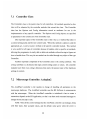
7.1 CONTROLLER CLASS ....................................................................................................................... 46
7.2 M ICROSCOPE CONTROLLER: A xIOPLAN2 ........................................................................................ 46
7.3 C AM ERA CONTROLLER: AxioCAm ................................................................................................. 48
7.4 X Y STAGE CONTROLLER: M A C5000 ............................................................................................. 49
8
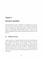
EX TEN SIO N CA PA BILITIES .......................................................................................................... 50
8.1
ADDING NEW DEVICES .................................................................................................................... 50
8.2 A DDING NEW CONTROLS TO AN EXISTING DEVICE ........................................................................... 52
8.3 A DDING NEW CONTROLS TO THE GU I ............................................................................................. 53
9
8.4 ADDING NEW PROTOCOL COMMAND TO SERVER .............................................................................
53
8.5 ADDING NEW PROTOCOL COMMAND TO CLIENT ..............................................................................
54
POSSIBLE IMPROVEMENTS AND FUTURE WORK ............................................................
55
10 CONCLUSIONS..................................................................................................................................
58
APPENDIX A: TA USER M ANUAL .....................................................................................................
59
APPENDIX B: STUDENT USER M ANUAL .......................................................................................
62
REFERENCES ...........................................................................................................................................
65
6
List of Figures
Figure 1 - Rem ote M icroscope GU I.................................................................................
Figure 2 - Poly(ethylene oxide) crystallized at 55.5 C [9]..........................................
Figure 3 - Zeiss AxioPlan 2 Im aging.............................................................................
Figure 4 - Zeiss A xioC am MRc .......................................................................................
Figure 5 - LUDL XY Stage System with MAC5000 and Joystick ...............
Figure 6 - Linkam LTS 350 Heating Stage with TMS94.............................................
Figure 7 - System Overview Diagram..............................................................................
Figure 8 - GU I Im age Panel ..........................................................................................
Figure 9 - GU I M icroscope Panel .................................................................................
Figure 10 - GUI M essage Panel ...................................................................................
Figure 11 - Module Dependency Diagram for Client Application................................
Figure 12 - Module Dependency Diagram for Server Application ...............................
11
13
18
18
19
20
22
30
31
32
33
40
42
Figure 13 - Server class threads....................................................................................
Figure 14 - Module Dependency Diagram for Hardware Controllers..........................45
51
Figure 15 - New Controller Module Template.............................................................
List of Tables
Table 1
Table 2
Table 3
Table 4
Table 5
- Client Commands to Server..........................................................................
- Server Commands to Client..........................................................................
- AxioPlan2 Controller Settings ........................................................................
- AxioCam Controller Settings........................................................................
- MAC5000 Controller Settings ........................................................................
26
27
47
49
49
Chapter 1
Overview
The main purpose of this thesis is to set up and develop the necessary hardware and
software to setup a Remote Microscope to conduct Polymer Crystallization Experiments
via a web-enabled interface. This project is part of the iLab research project at MIT that
aims to develop a new framework for science and engineering education. The goal of
iLab is to build web-accessible remote laboratories that allow real-time experiments from
anywhere at any time. The underlying educational principle of the iLab project is the
conviction that students are more motivated and learn better if they conduct experiments,
compare reality with simulations, collaborate with each other, and are allowed to explore
a physical system following their curiosity [2].
The Polymer Crystallization experiment is a standard experiment in polymer
science, but it has rarely been offered at MIT because of the limited availability of
polarized light microscopes, heating stage, and photographic equipment. In addition it has
been hard to schedule group of students to work with a single microscope at the same
time. The students will benefit from having this lab online because it will allow them to
access a high-end piece of equipment such as a light microscope and heating stage. They
will have more flexibility to run the experiments over a wide range of hours, and when it
suits their own schedules.
The students will also have the opportunity to repeat the
experiment as many times as they want, after data of an earlier experiment is analyzed, to
encourage learning through iteration. In addition, with the online setup, the experiment
9
could easily be demonstrated in a lecture setting.
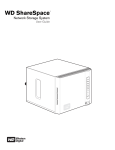
The Remote Microscope System is the first big step towards the completion of an
entire Polymer Crystallization WebLab. The Remote Microscope System consists of a
light microscope, a digital camera and an XY stage, all controlled via a web-enabled
interface. In future releases of the project the system will have a heating stage controlled
via a web-enabled interface as well. The current system allows the user to remotely
control and view a microscope over the Internet. The system consists of a graphical user
interface client that can run in any browser or platform.
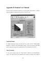
Figure 1 shows what the
graphical user interface looks like. The client is able to display images that are captured
by the digital camera; it displays real-time video, and is able to display real time status
messages.
In addition the user is able to do autofocusing of an image remotely, and
change a number of the microscope settings.
The overall software system consists of a client application that can connect to a
server process running on a Windows PC. This server process is able to communicate
with the hardware through several implemented software controllers. Currently only one
client can connect to the server at any given time, since no more than one client should be
controlling the microscope at any given time.
10
ILab Microscope
Reload
Back
SBookmarks
S
G
I
'IXI 1
- Netscape
View Go Communicator
File Edit
f
Hetp
Home
Netscape
Seatch
Secunty
Prin*
Locatiorc ile:///CILab/RemoteMicroscope/microscope. html
Yoogle
YahoolMail
[jI YahoolCalendar
j
Weather com
!
Hotmail
1
t MyBookme
MyHomepage
Webmail
Done capturing image.
S
f-
Document: Done
V
Figure 1 - Remote Microscope GUI
11
4
-
-~
~
-~----~--~--,
- -- ---
~
----.-
-~----
- -
Chapter 2
Background
This chapter will cover background information relevant to the Remote Microscope. It
will start by describing the experiment intended to run with this Remote Microscope
System. It will then go to describe existing remote microscope systems, and will later
describe the related Framework Project. A brief overview of the programming tools used
in the system will also be given at the end of the chapter.
2.1
Polymer Experiment Overview
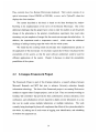
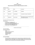
The polymer crystallization experiment lends itself particularly well for an online realtime experiment.
The experiment is such that, once the sample is set up in the
microscope, the experiment can be cycled repeatedly without operator intervention. The
aim of the experiment is to measure the rate of crystallization and relate this to polymer
crystallization kinetics, as well as to measure the rate of volume transformation and to
determine the Avrami exponent of thin film crystallization. The experiment consists of a
polymer sample that is raised above its melting temperature.
Then it is dropped to
different levels of cooling, where the polymer will start to crystallize. The student will be
able to see the growing crystallites, and will have to record the rate of growth of the
12
spherulites.
Figure 2 - Poly(ethylene oxide) crystallized at 55.5 C [9]
2.2
Existing Remote Microscopes
A remote microscope was developed here at MIT by James Kao [3] as part of the
Computer Integrated Design and Manufacturing project to help in the remote fabrication
of integrated circuits. It allowed users to operate a microscope, and view a static image of
the circuits remotely. It also allowed multiple users to view the same image at the same
time for conference inspection. This microscope system was later extended by Somsak
Kittipiyakul, which added complete automation of the microscope [4]. Currently the
microscope is no longer running, but there is considerable amount of literature from
which we were able to learn from for our own design.
In addition there is open source code of a server and client for a Remote
Microscope implemented by Andrew Kuchling for the MEMS Exchange project'. The
MEMS Exchange has deployed this fully automated and remotely controllable
microscope that is used for semiconductor inspection. It allows MEMS designer to view
wafers after critical processing steps from any location having an Internet connection.
1http://www.mems-exchange.org/software/microscope/
13
They currently have five Remote Microscopes deployed. Their system consists of an
optical microscope (Leica INM200 or INS1000), a server, and a Python/Tk client that
displays the client interface.
The system described in this thesis is based on the ideas developed by Andrew
Kuchling in his implementation of the server of the Remote Microscope. One of the
additional challenges that this project faces is that in order for students to see the growth
change of the spherulites in the polymer crystallization experiment, they need video
streaming, not just snapshots of images like the remote microscopes described above. In
addition, the experiment needs a temperature control,
which means the additional
challenge of adding a heating stage that works with the whole system.
We found that the existing remote microscopes have implementations specific to
the application of the microscope. In our project a great deal of focus was placed on the
extensibility of the system, so that the same software architecture could be used for
different applications of the system.
Chapter 8 discusses in detail the extensibility
possibilities of the system.
2.3
I-Campus Framework Project
The Framework Project is part of this iCampus initiative, a research alliance between
Microsoft Research and MIT that aims to enhance University education through
information technology. The focus of the Framework project is on creating Web service
modules to support other iCampus projects, such as iLab. They are currently working on
building "lab controllers" that provide the basic authorization, resource allocation, event
notification, and collaboration services required to deploy on-line laboratories in a way
that can be scaled across multiple laboratories at multiple institutions.
The work
currently being developed by them will complement the efforts of the system described in
this thesis, by making use of such events as logging, user identification, and scheduling
of students for equipment use.
14
2.4
Development
This section provides an overview of the programming languages used for the
implementation of the Remote Microscope System.
2.4.1
Java
The client module is built entirely in the Java programming language. Java was
developed by Sun Microsystems Inc. The Java language is a high-level and portable
language. The great advantage of Java is that it allows programmers to develop platform
independent applications.
Java is an Object Oriented Programming language. In brief, this means that all the
code is contained within objects known as classes. Each class has its own set of variables
and methods, and objects in a system will interact by calling other object's methods.
One of the great advantages of Java is that it enables the programmer to write
programs called applets that can run embedded into Internet Web Pages. An applet is an
object in java that allows Java code to be downloaded over the network and run within a
Java Virtual Machine (JVM), which nowadays is part of all web browsers [8]. Therefore,
by using a Java applet, users would not need to download any extra software to run a
program. All they need to do is connect to the appropriate URL using a web browser.
2.4.2
Python
The server and hardware modules are implemented in Python: an interpreted, interactive,
object-oriented programming language, which is often compared to Tcl, and Perl [11].
Guido van Rossum, who is currently employed by the Corporation for National Research
Initiatives (CNRI), first developed Python in 1990. The home page for the language is at
www.python.org and is hosted by CNRI.
Python is very simple and powerful. One of the advantages of Python is that it has
an interactive mode, where the programmer can enter expression one line at a time. This
15
mode allows the programmer to try ideas quickly and cheaply, testing each method as it
is written. Python also makes parsing strings very easy, and has built-in high-level types
such as lists and dictionaries, which help in programming and usually mean writing less
code.
To some extent Python is also platform independent.
The core language and
standard libraries are identical across Windows, Unix and Macintosh platforms, although
each platform offers its own dedicated extension.
16
Chapter 3
Hardware Overview
This chapter describes the hardware setup of the Polymer Crystallization WebLab. It
describes in detail each hardware component, and explains its features.
The second part
of this chapter gives an overview of the vendor software that can be used to control
certain hardware components from a PC.
3.1
Hardware Setup
3.1.1
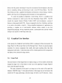
Zeiss Axioplan 2 Imaging
The Zeiss Axioplan 2 Imaging is a motorized light microscope.
It is a flexible
microscope system that can be tailored to several applications. It is currently setup for
polarized and transmitted light only, but if needed the reflected light module could be
purchased in the future as well. The microscope can be manually controlled or computer
controlled.
17
Figure 3 - Zeiss AxioPlan 2 Imaging
3.1.2
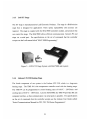
Zeiss AxioCam MRc
When the Zeiss Axioplan
imaging workstation.
is combined with the AxioCam it provides a real digital
When the AxioCam takes pictures the images are available
immediately on the PC screen. It is a color camera that has a resolution of up to 1300 x
1030 pixels. It creates a fast live image, and has adjustable ROI (Region of Interest) and
binning.
Figure 4 - Zeiss AxioCam MRc
18
3.1.3
Ludl XY Stage
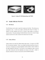
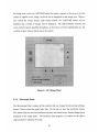
The XY stage is manufactured by Ludl Electronic Products. The stage is a BioPrecision
stage that is designed for applications where speed, repeatability and accuracy are
required. The stage is coupled with the MAC5000 controller module, and joystick that
can control the stage. The MAC5000 allows efficient communication between PC and
stage via a serial port. For specifications on the set of commands that the controller
accepts see the Ludl manual titled "MAC 5000 Programming".
Figure 5 - LUDL XY Stage System with MAC5000 and Joystick
3.1.4
Linkam LTS 350 Heating Stage
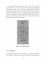
The fourth component of our system is the Linkam LTS 350, which is a large-area
heating stage. The TMS 94 is the temperature controller used with the heating stage.
The TMS 94 can be programmed to control heating rates of 0.01'C - 130'C/min. and
cooling rates of 0.01*C - 100 0C/min. Like the MAC5000, the TMS 94 provides RS 232
computer interface, so that communication via serial ports is possible. For specifications
on the set of commands that the controller accepts see the Linkam User Guide called:
"Serial Communications Manual for T92, T93, T94 Series Programmers".
19
Figure 6 - Linkam LTS 350 Heating Stage with TMS94
3.2
Vendor Software Overview
3.2.1
KS Software
The KS Software can be used to control the Axioplan and AxioCam. This software was
developed by Zeiss.
It allows easy capture, processing and saving of an image.
In
addition it provides additional tools such as autofocus, light manager, and setting of
manual controls. The great advantage of the KS Software is that it has a variety of image
analysis tools that can be used to measure and evaluate areas of an image.
3.2.2
Linksys Software
Linksys software can control the Linkam heating stage system. It connects to the TMS
94 via a serial port connection. It has a very simple user interface that allows the user to
set the rate of temperature, the target temperature and the amount of time to remain on
the target temperature (hold time). It also allows for the temperature ramp to start and
stop, while viewing the real time temperature and status on the screen.
basically a reflection of what you can see and do with the TMS 94 hardware.
20
Linksys is
.'i
NOW
Chapter 4
System Architecture
In the previous chapter we discussed the various hardware components of the Remote
Microscope.
This chapter gives an overview of the software system architecture.
Chapters 5, 6, and 7 will describe in more detail the exact implementation of each
software component. The purpose of this chapter is to familiarize the reader with the
client and server applications, as well as the underlying client/server communication
protocol.
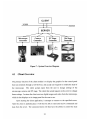
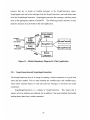
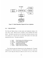
The software architecture consists of two main components: a server and client.
The server and client communicate via TCP/IP socket interfaces, using a simple but welldefined message protocol that can send or receive messages from server to client and vice
versa. A third component is the hardware control. The hardware controllers are modules
that contain specific methods that communicate with the hardware to set certain settings
and to get the hardware status. Figure 7 shows how the software components interact in
our remote microscope system.
21
CLIENT
Internet
TCP/IP
SE RVE R
Microscope
Camera
XY Stage
Hot Stage
Controller
Controller
Controller
Controller
Figure 7 - System Overview Diagram
4.1
Client Overview
The primary function of the client module is to display the graphics for the control panel
that runs remotely through a web browser, and accept user requests to modify the state of
the microscope.
The client accepts input from the user to change settings of the
microscope, camera, and XY stage. The client then sends requests to the server to change
these settings. In return the client receives digital images and video from the microscope,
which it then displays on its image panel for the user to see.
Upon starting the client application, it attempts to connect to the specified server.
After the client is authenticated, it will then be able to send and receive commands and
data from the server. The connected client will then have the ability to control the state
22
of the microscope, stages and camera.
To create the Graphical User Interface (GUI) and display the graphics on the web a
Java applet was used, which is described in more detail in Chapter 5. The user interface
is designed for student's use, which restricts the type of commands they can send to the
microscope server, and only allows those necessary for the experiment. It is important
for the student user interface to be adequate for educational purpose, and easy enough to
use, so that it facilitates the learning and the experiment analysis.
4.2
Server Overview
The server is responsible for relaying messages from client to the appropriate hardware
controller, and keeping the state of the system. It receives and parses client request
messages, and then forwards these messages to the corresponding controller module. In
addition the server is constantly listening for new client connections. Due to the specifics
of the experiment, the server does not allow more than one client to connect to it at a
time, and sends messages of "No Connection Possible" to other clients trying to connect.
In conjunction with the microscope server, there is also an HTTP server running.
The HTTP server acts as the network server for the client. It allows the client browser to
interact with the server using the standard HTTP protocol.
Both the microscope and
HTTP servers are written in Python. For the server implementation details see Chapter 6.
4.3
Hardware Controllers
The controller modules are in charge of handling all interactions between the software
and the actual hardware. For example, when a client requests a change in XY position,
the server will forward this request to the XY Stage Controller. Then the XY Stage
Controller will communicate with stage over the serial port to make the desired changes.
It will then inform the server when it is done.
23
Controllers are also in charge of maintaining their own state. Each controller stores
the present values of the settings it controls, which is then used by the server to maintain
the entire state of the system. For the controller implementation details see Chapter 7.
4.4
Client/Server Protocol
The server and client communicate via TCP/IP socket interfaces, using a simple but welldefined message protocol that is based on Andrew Kuchling's remote microscope
implementation for the MEMS project [6]. The advantage of this messaging abstraction
is that it is very easy to update and change the individual client and server modules
without having to make a change on the whole server system. In addition, we have the
flexibility of choosing any programming language for the client or server, as long as they
can send messages to each other.
The messaging protocol consists of single lines of ASCII text sent back and forth
between server and client. Images are sent in binary form as a series of messages over a
separate TCP/IP socket connection.
Messages are designed to be human readable and are sent asynchronously. This
means that there is no expectancy of a response after a message is sent by either party.
Instead, the client sends a message to server, who then processes it, and may either ignore
it, or generate more messages back to the client. Either way the client will not be waiting
for a server response after it sends a message. The reason for choosing this protocol is
because of the unreliability that the Internet brings. We cannot be 100% sure that the
server will receive a message, therefore the client could wait forever for a response,
instead of continuing its normal operation.
Messages are single lines of text ending with a new line (\n). The first word of the
line is the message name, followed by the parameters required by the command.
Parameters are of the form parameter name=value, where value can be a single word,
number, or a quoted string. Command names and parameter names are case-insensitive,
and the order of the parameters is not significant. Some parameters are optional, and
others are not, but as long as the message ends with a new line, either client or server will
24
be able to parse the message.
Some examples of messages are:
SET magnification=10X x=10 y=10
CAPTURE sizeX=1300 sizeY=1200 mode=RGB
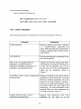
4.4.1 Client Commands
The following table shows commands that are sent from the client to the server.
Command
Explanation
AUTH authtoken
Request to authorize this client. authtoken
is a base64-encoded, compressed text
string. When decoded and uncompressed it
contains a signature and info string used for
authentication.
AUTOFOCUS
Performs autofocusing by searching for the
best z-focus position.
SET x=val y=val magnification=val
lightMode=val lightVoltage=val
aperture=val fieldStop=val reflector=val
transFilter-val exposureTime=val
Changes the hardware settings and status.
All parameters are optional. Command can
be sent with one parameter, two, or all at
the same time. For a list of valid parameter
values see the controller's details in
Chapter 7.
CAPTURE sizeX=x sizeY=y mode=mode Request an image from the camera with the
format=format
specified size, mode and format. mode and
format are optional parameters, but sizeX
and sizeY are always required. If mode or
format are not specified the default values
are mode=L (black and white image), and
format=jpg. For more information on the
accepted values for these parameters see
the camera controller section 7.2
VIDEOSTART sizeX=x sizeY=y
mode=mode format=format
Requests video streaming to start. The
arguments are the same as in the
25
CAPTURE command above. mode and
format are optional, while sizeX and sizeY
are required.
VIDEOSTOP
Requests the video streaming to stop.
CENTER
Centers the XY stage.
SERVER
Prints out the server information such as
threads, port connections, and client
connections. This command is usually
used only for debugging.
STATE
Print out the server state information. This
command is usually used only for
debugging.
QUIT
The
Terminates the client connection.
server will remove the connection and
close the TCP/IP socket.
Table 1 - Client Commands to Server
4.4.2 Server Commands
The following table shows commands that are sent from the server to the client.
Explanation
Command
IMAGE length \n
binary data
Transmit image to client as binary data.
The message line includes the length of the
image data, followed by a new line, and
then the image binary data.
SCOPE x=val y=val magnification=val
lightMode=val lightVoltage=val
aperture=val fieldStop=val reflector=val
transFilter=val exposureTime=val
Inform clients of the microscope's current
settings (current state). For a list of valid
parameter values see the controller's details
in Chapter 7.
STATUS msg
Sends a message to client specifying the
status of the hardware (or what operations
are taking place).
26
ERROR msg
Sends an error message to client.
OCCUPIED
Message sent upon client initialization to
inform the availability of the scope.
AVAILABLE
Message sent upon client initialization to
inform the availability of the scope.
Table 2 - Server Commands to Client
27
Chapter 5
Client Implementation Details
This chapter describes the Remote Microscope client implementation in detail.
The
client interface is the main program to which the user of the Remote Microscope will
interact. The client module has three main tasks. It must first be able to display the
graphic controls to the user (including the image display), it must accept input from the
user to control the hardware settings, and finally it must parse or process the messages
sent from the server.
This chapter will start by giving an overview of the programming tools used to
implement the client application. It will then describe the graphical user interface built,
and will give specifications of the objects or modules in the client application, and show
how they relate to each other.
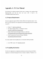
5.1
Programming Tools
The client application was programmed entirely with the Java programming language.
The latest version of Java, Java 2 SDK version 1.4.0, was used. In addition an integrated
development environment (IDE) for Java technology called Forte for Java, (Community
Edition v3.0) was used for development.
This development environment contains
various coding, editing, compiling, debugging, and source code management tools. I
28
believe that the greatest advantage of using this environment for development, other than
ease in compiling, editing, and browsing of code, is the GUI Form Editor. The GUI
Form Editor provides a graphical development environment to create dialogs, windows,
applets, allowing for easy debugging and development of visual applications.
To create the graphical components I used Swing, which is a graphical user
interface component kit, which is part of the Java Foundation Classes (JFC). The JFC
extends the original Abstract Window Toolkit (AWT) and encompasses a group of
features to help people build GUIs. Swing is integrated in the Java 2 platform, and there
is no need to download or install it. Swing simplifies deployment of applications by
providing a complete set of user-interface elements written entirely in the Java
programming language. Swing components permit a customizable look and feel without
relying on any specific windowing system [12].
5.2
Graphical User Interface
At the present, the Graphical User Interface (GUI) is composed of three main panels: the
Image Panel, the Microscope Panel and the Message Panel. Panels are general-purpose
containers for various components that usually don't paint anything other than their
background, and border. In the future there will be a fourth panel that will correspond to
the display of the Linkam hot stage controls.
5.2.1
Image Panel
The main function of the Image Panel is to display images, as well as enable controls that
change the image view or that relates in some way to the capturing of images. Figure 8
shows what this panel looks like.
The main component of this panel is an image icon in the center of the panel that
displays a 260x206 image. To the right and bottom of the image icon we find arrows that
control the XY stage positioning so that the image will shift in an XY direction. Above
29
the image icon we have a CAPTURE button that sends a request to the server to tell the
camera to capture a new image, so that it can be displayed on the image icon. When a
user selects the Video Stream radio button bellow, the CAPTURE button will be
disabled, and a stream of images will be displayed. The high-resolution controls and
zoom controls remain disabled throughout, as they have not been implemented yet, but
could be of great value to future use of the system.
Figure 8 - GUI Image Panel
5.2.2
Microscope Panel
The Microscope Panel contains all the controls that can change the microscope settings.
Figure 9 shows what this panel looks like. On the top we have the Autofocus button.
This button calls the one-time autofocus function, and returns a new focused image that is
displayed on the image panel. The autofocus main purpose is to search for the right z
stage position for adequate focusing.
30
The magnification control changes the objective being used.
The possible
magnifications are: 2.5X, 5X, 1OX, 20X, and 50X. The aperture control changes the
condenser aperture setting. This is useful mainly in magnifications greater than 1OX,
because in lower magnifications the field of vision will be greatly reduced. The field stop
controls the light intensity. This control is useful mainly for the lower magnifications of
2.5X, and 5X. In addition we have three possible settings for the reflectors. There is an
analyzer, a DICRED reflector, and no reflector at all. Finally, we have the exposure
time that controls the shutter speed of the camera.
Figure 9 - GUI Microscope Panel
5.2.3
Message Panel
The Message Panel displays two types of messages. First it displays status messages.
These messages are sent by the server to inform which operation is being performed at
31
any given time on the server side. In addition, if any type of error occurs or an exception
is thrown on the server side, a message will appear in red on the Status Panel.
STATUS Message
ERRmessage
Figure 10 - GUI Message Panel
5.2.4
Temperature Panel
The Temperature Panel has not been implemented yet. This panel should include
controls to set the temperature rate, the temperature target, and the hold time of the target
temperature. It should include a START and STOP buttons to indicate when heating or
cooling should start. Finally it should include a temperature display that displays the
present temperature in real time.
5.3
Class Specifications
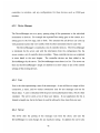
The main class of the client application is a Java Applet class called ScopeApplet. As
mentioned before Java Applets are programs that can have compiled code stored in a
remote host, and can be run from any Java enabled web browser [7]. Figure 11 shows
how the ScopeApplet interacts with all the other components in the client application.
The ScopeApplet class first creates two objects used for communication with the
server: ScopeConnection, and ScopelmageConnection.
These objects are in charge of
creating socket connections with the server, and to send and receive messages to and
from the server. In addition the ScopeApplet creates a ScopeGUI object. The ScopeGUI
object creates all the graphical control panels and graphical components. The ScopeGUI
inherits two interfaces: IScopeControls and IScopeProtocol, and contains a set of event
32
listeners that are in charge of sending messages to the ScopeConnection object.
ScopeApplet reads and writes messages from the ScopeConnection, and reads binary data
from the ScopelmageConnection. ScopeApplet processes the messages, and then passes
them to the appropriate method in ScopeGUL.
The following sections describe in more
detail the function of each module in the client application.
Mads
ScopeApplet
(Main)
To Server
Fram Server
0
Scope
Image
Connection
To
6
From
Ln
IScopeControls
ScopeGUI
rScope
s
Server
IScopeProtocol
Connection
Event
Listeners
Figure 11 - Module Dependency Diagram for Client Application
5.3.1
ScopeConnection and ScopelmageConnection
The ScopeConnection class is in charge of creating a socket connection to a given host
name and port number. The two main methods are sendMessage() and readMessage(),
which allow external objects to write and read text messages to and from the socket
connection.
ScopelmageConnection is a subtype of ScopeConnection.
This means that it
inherits all of its attributes and methods, but in addition it has some methods that handle
reading binary data from a socket connection.
33
5.3.2
IScopeControls and IScopeProtocol
IScopeControls and IScopeProtocol are both interfaces. Interfaces are essentially a
collection of constants and abstract methods.
Abstract methods are methods that are
declared but not defined. In other words the bodies of these methods are empty.
To make use of an interface you implement the interface in a class, and in that class
you write the code for each of the methods in the interface. Any constants or attributes
that are defined in the interface are also available in the class [1]. The purpose of having
an interface is that it can act as a protocol definition between two independent systems
that communicate with each other. In our case it serves as a communication protocol
between the server and client, and will also aid in the extensibility capabilities discussed
in Chapter 8.
IScopeProtocol contains a list of methods called "cmd_<commandname>", where
<commandname> are all the possible commands that the server can send to the client.
For a detailed description of these commands see section 4.4.2. Bellow you can see what
this interface looks like. All methods, with the exception of the image command, take in
a String of the arguments to the command. For example, for the STATUS command the
args String will contain the status message string sent from the server.
public interface lScopeProtocol {
void cmdscope(String args);
void cmdstatus(String args);
void cmderror(String args);
void cmdimage(byte[] image);
void cmdoccupied(String args);
void cmdavailable(String args);
}
IScopeControls contains a list of methods called "set_<controlname>", where
<controlname> are all the possible controls (or settings) that the server can send values
for. For a detailed description of these controls see Chapter 7. Bellow you can see what
the interface looks like.
public interface IScopeControls {
Hashtable state = new HashtableO;
void set-aperture(String strValue);
void set-magnification(String strValue);
34
void
void
void
void
void
void
void
void
setjlightVoltage(String strValue);
setiightMode(String strValue);
setreflector(String strValue);
settransFilter(String strValue);
set-y(String strValue);
set-x(String strValue);
set-exposureTime(String strValue);
set_fieldStop(String strValue);
}
It is important to note that even if the client does not need a certain control (for
example if the GUI does not have a component for the transmission filter control) the
following methods still need to be declared in the class that implements this interface,
even if they are left empty. The whole point of having declared this interface is because
when the command SCOPE is sent from the server to the client it will send the state
values of ALL the controls the server can handle. Since the client application calls the
set methods automatically by their names, "set_<controlname>", if any of these
methods fail to appear in the implementation class then an error will occur. The main
purpose of the interface is to keep a record and maintain a protocol of which controls the
server implements, so that the client knows which methods it has to have.
Another important component to note about IScopeControls is the Hashtable called
state.
A Hashtable is basically a table that matches key names to values. This state
object will be inherited in the class that implements this interface, and will aid in
maintaining the state of all the control values. This Hashtable maps the control name to
its corresponding value, and should be updated by the class that implements this
interface.
5.3.3
ScopeGUI
The main function of ScopeGUI is to create and maintain the components of the
Graphical User Interface (GUI).
ScopeGUI creates and initializes all the Swing
components and panels, and it creates event listeners for each graphical component.
These event listeners are discussed in more detail in the next section.
35
ScopeGUI is also the class that implements the IScopeControls and IScopeProtocol
interfaces. Therefore it implements all the methods listed in these two interfaces, and
since it inherits the Hashtable 'state' from IScopeControls it is in charge of maintaining
the state of the client.
5.3.4
Event Listeners
Swing components can generate many kinds of events when a user interacts with them,
like pressing a button, or selecting an item from a list. In Java each event is represented
by an object that gives information about the event and identifies the event source,
meaning the component where the event was generated.
Each component can have
multiple listeners registered, and a single listener can register with multiple components.
I chose to have a single listener for each component to keep the handling of events in
separate methods.
These event listener methods reside in the ScopeGUI class, and
whenever an event happens these methods are called.
Event listeners have two tasks. One task is to respond to the component's events by
sending requests to the server to change the state of the hardware, or to request an image.
This is done by sending text message commands to the ScopeConnection. The second
task is to update the state Hashtable with a new control value, when the event requests to
do so.
5.3.5
ScopeApplet
ScopeApplet is the main class of the client application.
ScopeApplet extends the
JApplet 2 . In addition to having the capability of an Applet it creates three objects when it
initializes. It creates a ScopeConnection (used for reading and writing text messages to
and from the server), a ScopelmageConnection (used for reading binary messages from
2
For more information about JApplet or other Java defined classes see: "Java 2 Platform, Standard Edition,
version 1.4.0 API Specification," http://ava.sun.com/j2se/1.4/docs/api/index.htm
36
server), and a ScopeGUI (used to display the graphical components).
ScopeApplet is also in charge of listening to messages sent from the server, and
then processing them. It has a ReaderThread that with the aid of ScopeConnection is
constantly listening for text messages sent from the server. When a message is received
the message name is extracted from the string. This name is appended to 'cmd_' to
create a method name that is then called with what is left of the message string as
argument to the method.
In addition to the Reader Thread, there is a ReaderlmageThread that is constantly
listening for binary data from the server with the help of ScopelmageConnection. When
a binary message is received it extracts the binary information and calls the method
cmdjimage, with the binary data as an argument.
37
Chapter 6
Server Implementation Details
This chapter will describe the implementation details of the server application.
The
server runs on the Windows platform PC. The server is responsible for maintaining the
overall state of the microscope, accepting client connections, and processing messages
sent from client to send them to the appropriate controller module. When the server is
run, the application will remain idle until it receives a client connection.
The server implementation was based on Andrew Kuchling's Remote Microscope 3
implementation for the MEMS Exchange project. Kuchling implemented a server written
in Python that runs in a Linux machine [6].
His server code was used to aid in the
implementation of this server. Many of Kuchling's code structure was maintained, with
some changes made to the controller handling, state handling, and some other
modifications done so that the server will run in Windows.
Kuchling's server was designed to handle multiple connections to the server, so that
one client will act as the controller for the microscope, and other clients could connect as
viewers. Even though this was not a requirement for this project, the code is structured in
such a way that this feature could be added easily in the future.
3http://www.mems-exchange.org/software/microscope/
38
6.1
Programming Tools
The server application was programmed in Python. Python version 2.2 was used. In
addition a few Python add-on packages that can be downloaded from the web were used
to aid in the functionality of the server. For one, the Python Imaging Library (PIL) 4 was
used. The PIL adds image processing and graphics capabilities to the Python interpreter.
This package was used to handle the images sent from the camera.
A second package that was used was Win32all 5 , which was developed by Mark
Hammond as an add-on for the regular Python installer for Windows platform.
This
package includes Win32 API, COM support and Pythonwin. Pythonwin is an integrated
development environment (IDE) and GUI Framework for Windows. Pythonwin was a
very helpful tool that allowed the use of Python's interactive window, as well as editing
compiling, and running of Python files.
The third package used was the SioModule
,
a serial communication extension for
Win32 created by Roger Burnham from MarshallSoft Computing, Inc. This module was
used to aid in the connection between controller modules and serial ports.
6.2
Class Specification
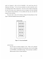
The main class of the server application is the SERVER class. The server uses various
classes or objects to aid in handling users connecting to it, parsing messages, sending
messages, and creating devices to be used. In Figure 12 you can see the objects that the
server uses.
The following sections explain in detail how each of the modules works
and the purpose they serve for the server application.
4 http://www.pythonware.com/products/pil/
5 http://starship.python.net/crew/mhammond/
6 http://starship.python.net/crew/roger/
39
To Client
I
H TTP
Server
SERVER
Config
Options
User
Device
Manager
Controlle
Device
Figure 12 - Module Dependency Diagram for Server Application
6.2.1
Config and Options
The Config and Options classes set certain options and configuration settings to the
server when it starts. When the server is launched, it can be initialized with several
options. The Options class parses the server initialization command, and keeps a record
of the options set, so that the server can knows which options were chosen upon
initializing of the server. The options available are:
-c, --center
-d, --debug
-f, --cfg <file>
-h, --help
-t, --timing
-v, --verbose
Center the stage when initializing microscope
Display debugging trace messages
Use specified configuration file
Display this help message
Display timing trace messages
Display verbose activity message
The Config class parses the information given by the configuration file. The default
configuration file is called microscope.cfg. The information in this file is used by the
server to know things like which port number the server will run at, which device
40
controllers to initialize, and any configurations for these devices such as COM port
numbers.
6.2.2
Device Manager
The DeviceManager acts as a proxy, passing along all the parameters to the individual
instruments or devices. For example the exposureTime setting goes to the camera, an x
setting goes to the XY stage, and so forth. This assumes that all devices can come up
with parameter names that won't conflict with the other instruments they're used with.
The DeviceManager is essentially a list of controller devices. The DeviceManager
is initialized by the server, and with the information from the configuration file, the
server creates a set of controller device modules. These controller devices are explained
in more detail in the next chapter.
The controller devices are then added to the
DeviceManager by the server. The DeviceManager stores them in a list. The server can
then use the DeviceManager's single set method to set new values to any of the control
settings of the existing devices.
6.2.3
User
User is the class representing a user of the microscope. A user will have a unique id for a
connection, a name, and two socket connections (one for text messages and one for
binary data). A user is initialized with the given client authorization token, which is then
validated. The server stores a list of these user objects. In our application the list is
limited to length one, but in the future it could be allowed to have more than one user.
6.2.4
Server
The server does the parsing of the messages sent from the client, and uses the
DeviceManager to send changes for any hardware setting. In addition the server also
41
sends text messages to client, and most importantly it also sends binary data for
displaying of the image. To do so, the server maintains two socket connections, one for
text messages and the other for binary data. The server is also in charge of maintaining
the state of the system, and of sending status and error messages to the client informing
of the operations being performed, or of any problems that may arise with either the
hardware or server software.
The server class is where all the listening, reading and writing threads are fired.
Figure 13 shows the threads that run in the server class.
Main Server Program
Listener Thread
Listener2 Thread
Reader Thread
Writer Thread
HTTP Thread
Figure 13 - Server class threads
Listener Thread
Sits and waits for connection requests to arrive. When a new connection
arrives, it informs the connection if the microscope is free or not by sending
an OCCUPIED or AVAILABLE message. If the microscope is available it
adds the socket to the list of client connections.
42
Listener2 Thread
Listens for connections on the imagesocket connection.
This socket
connection has a different port number than the main socket connection, and
that is why we need a separate listening thread.
Reader Thread
The reader thread watches the client sockets for incoming input. When a
command
comes
in,
the
corresponding
method
is
called:
cmd_<commandname> automatically. Then this method does whatever it
needs to do, usually calling a hardware method with the use of the
DeviceManager.
Writer Thread
The writer thread is awoken when messages are added to its outgoing queue,
and writes them to all the authorized client sockets
HTTP Thread
The "http" thread runs the http-server that is discussed in the following
section.
6.2.5
HTTP Server
Java applets running in a browser have the security limitation that they can only make
network connections back to the host from which they came. This means that the client
compiled code needs to exist in the same computer in which the server is running. In
order for remote running of the applet, the Remote Microscope needs to run an HTTP
server that will return the JAR file (compressed file for java files) containing the applet.
HTTP is an Internet Protocol used to exchange data across the network. The HTTP
server of the Remote Microscope system is set up to accept connections from client
computers, where the client issues a request to read an html file. The HTTP server then
locates the content, and sends the data back to the client computer.
43
6.3
Video Streaming
Video streaming is handled by an additional thread in the server class.
When video
streaming is requested to start by the client with the VIDEOSTART command, the
video thread is started.
With the help of the DeviceManager, this thread calls the
getjimage() method of the camera controller repeatedly. The thread keeps running until
the client sends the message VIDEOSTOP to request the server to stop calling the
getjimage() method so that the video streaming will stop.
44
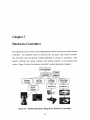
Chapter 7
Hardware Controllers
This chapter gives an overview of the implementation details and settings of the hardware
controllers. All controller classes are derived from the parent class called Controller.
The Controller class has general methods applicable to all type of controllers.
Each
specific controller has unique attributes and methods specific to the hardware they
control. Figure 14 shows the hardware controller's module dependency diagram.
Due ceManager
I
K
Controler
f
ECon ffg
tjn
Options
Axoplan
"Ainta
Controller
Controller
KS 300
LudlStage
Controller
LinkaniStage
Controller
Serisd Por
Serid Part
Softwre
Figure 14 - Module Dependency Diagram for Hardware Controllers
45
7.1
Controller Class
The Controller class is the parent class for all controllers. All methods specified in this
class will be inherited by the controller modules that extend this class. The Controller
class has the Options and Config information stored as attributes for use in the
implementation of any specific controller. The Options and Config objects are specified
as parameters to the constructor of the Controller class.
One important aspect of the Controller class is that it has a set method that takes in
a control setting name and the new control value. When this method is called, it calls the
appropriate get_<controlname>method in the specific controller module. This method
is very useful for all types of controllers because it handles calls to specific set methods,
allowing the programmer to easily add or delete set methods without having to figure out
how to handle them. This way the set method can be called through any object of the type
Controller.
Another important component of the Controller class is the settings attribute. The
settings attribute is a dictionary that maps control setting names to values. All controller
modules have their own settings dictionary that stores the present state of the hardware
settings it controls.
7.2
Microscope Controller: Axioplan2
The AxioPlan2 controller is the module in charge of handling all operations to the
microscope hardware. The AxioPlan2 controller uses the KS Software to communicate
with the microscope.
When the AxioPlan2 controller is initialized it has to create a
connection dispatch to the KS Application, so that it can then send command messages to
change the microscope's state.
Table 3 lists all the control settings that the AxioPlan2 controller can manage, along
with their types, their accepted values, and the default value given when the server is
46
restarted. The AxioPlan2 controller contains set and get methods for each control setting
All control settings names along with their present values are stored in the
name.
Axioplan2's settings dictionary, which is updated every time a set_<controlname>
method is called. The get methods are only used to retrieve the value of a control name.
The set and get methods should always be used for accessing or changing the settings
dictionary, instead of using the settings dictionary directly.
Control
Setig NType
Possible Values
Setting Name
Default Value
"5X"
magnification
String
lightMode
String
"2.5X", "5X", "10X", "20X", "50X"
"OFF", "3200K", and "MANUAL"
lightVoltage
float
[0.4 -> 12.2]
5.0
aperture
float
[0.07 -> 0.95]
0.95
fieldStop
float
[0.00 -> 1.00]
1.00
reflector
String
transFilter
String
"NONE", "ANALYZER", "DIC RED"
"0%", "0.048%", "0.100%", "0.200%",
"OFF"
"NONE"
"12%"
"0.400%", "0.720%", "1.5%", "3%", "6%",
"12%", "25%", "50%5", "100%"1
Table 3 - AxioPlan2 Controller Settings
Currently only the magnification, aperture, fieldStop and reflector settings can be
directly modified by the client interface. The lightMode setting is directly controlled by
the server application.
Whenever a client connects to the server, the lightMode is
switched to "3200K" value, and will automatically be set to "OFF" whenever the client
disconnects. The reason for giving control to the server instead of the client for this
setting is so that the light would not be left turned on after a client disconnects, and is no
longer using the microscope.
The lightVoltage and transFiltersettings are currently not being used by the client
or server. The setting lightVoltage is only used when lightMode is set to "MANUAL".
This control setting was not added to the client because for image viewing purposes it is
47
better to have the halogen lamp set to 3200K, and only modify the aperture or field stop
settings instead of the light voltage.
The transFilter setting which controls the
transmission filter is a setting that could be added in the future to the client interface, but
was not necessary for the present state of the project.
Aside from these settings the AxioPlan2 has an autofocus() method that request the
KS software to perform autofocusing.
Camera Controller: AxioCam
7.3
The AxioCam controller is the module in charge of handling all operations on the digital
camera.
Similar to the AxioPlan2 controller, the AxioCam controller uses the KS
Software to communicate with the camera. When this controller is initialized it has to
create a connection dispatch to the KS Application, so that it can then send command
messages for image processing capabilities.
The AxioCam controller has the important method getlimage() used to capture an
image from the camera. The getjimage() method takes in three parameters, two of which
have default values. The first one is the size of the image specified in pixels. The second
parameter is the image mode. The mode of an image defines the type and depth of a
pixel in the image. The KS software supports the following standard modes:
1 (1-bit pixels, black and white, stored as 8-bit pixels)
L (8-bit pixels, black and white)
P (8-bit pixels, mapped to any other mode using a color palette)
RGB (3x8-bit pixels, true color)
RGBA (4x8-bit pixels, true color with transparency mask)
CMYK (4x8-bit pixels, color separation)
YCbCr (3x8-bit pixels, color video format)
I (32-bit integer pixels)
F (32-bit floating point pixels)
The default value for mode is "L" which corresponds to capturing a black and white
image.
The last parameter is the image format. This specifies what type of file the image
48
will be stored at. The possible values for the format are "jpg", "tif", "bmp", and "pcx".
The default value format is "jpg"as this is the most compressed image format suitable for
image sharing through a network.
In addition the AxioCam has a single control setting to set: exposureTime. This
sets the shutter speed of the camera.
Control Setting Name
exposureTime
Type
Integer
Possible Values
[ims - 1,OOOms]
Default Value
ims
Table 4 - AxioCam Controller Settings
7.4
XY Stage Controller: MAC5000
The MAC5000 controller module is in charge of communicating with the XY stage
hardware. The MAC5000 uses the SerialPort class to create a COM port connection, and
be able to write and read from the COM port. The settings that the MAC5000 controller
handles are the X and Y position of the stage. In addition to these settings, it also has a
center-stage() method, which calibrates the stage and sets the position to the center of the
stage. This operation can be performed whenever the server is initialized or if a client
sends the CENTER command.
Control Setting Name
Possible Values
Type
x
integer
[-300000
Y
integer
[ -30000
->
->
300000]
0
220000]
0
Table 5 - MAC5000 Controller Settings
49
Default Value
Chapter 8
Extension Capabilities
The Remote Microscope system was designed for easy extendibility and usage with a
great sort of devices.
It allows new devices to be easily added since each hardware
device is encompassed with a single controller module. The system also allows new
controls to be easily added to individual controller modules, as well as to the GUI.
Furthermore, additional client/server protocol commands can easily be added to the client
and server.
8.1
Adding new devices
To add a new device, a new controller module has to be created. This controller module
has to be a Python class that extends or is of type Controller. Whenever a new device is
being
created
a
new
Python
class
file
should
be
placed
under
the
RemoteMicroscope\hardwaredirectory. This file should be given a name that describes
the hardware it controls such as AxioCam or Axioplan2.
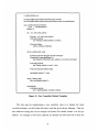
The following figure is a
Python file template that shows what the structure of a new controller module should
look like. As it can be seen from the class declaration line, the new device class is of
type Controller.
50
# <newDeviceName>.py
from RemoteMicroscope.hardware.Controller import Controller
from RemoteMicroscope.hardware.InstrumentException import InstrumentException
class <newDeviceName>(Controller):
-name- ='<newDeviceName>'
settings = {}
def _init_(self, config, options):
Controller.__init_(self, config, options)
if self.options.verbose:
print "Initializing <newDeviceName> controller..."
# Set initial settings
self.set_<setting1 >(<initialVal>)
def set_<settingl>(self, value):
# Checks to see if the value given is of the correct type
if (type(value) !=type(<typeSetting1 >)):
raise TypeError ("Parameter to set_<settingi> is not of the correct type.")
if self.options.verbose:
print "Setting <settingi> to value: ",value
# Add code that sets hardware setting
self.settings['<settingl>'] = value
def get_<settingl >(self):
return self.settings['<settingl >']
def close(self):
if self.options.verbose:
print "<newDeviceName> controller is closing"
Figure 15 - New Controller Module Template
The first step for implementing a new controller class is to replace the name
<newDeviceName> on the Python file above with the given device filename. Then for
each hardware setting that can be changed, the Python file should contain a set and get
method. An example of how these methods are defined and what most be in them are
51
exemplified above with the set_<settingl> and get_<setting]> methods.
values should be initialized in the constructor (
init
All setting
) method, by replacing <initVal>
with the initial value for the corresponding setting. If this is not done, the setting name
will not appear on the settings dictionary of the device, and the setting will not be taken
into account until the set method is called for the first time.
In addition to set and get methods, the controller module may have to implement
additional methods that do not correspond to changing hardware settings, but that
produce an action on the hardware or add additional functionality to it. There is no
restriction on how these methods should be implemented, but the programmer should
make sure that the server application can call these methods appropriately. In most cases
this means adding an additional client/server protocol command that handles these
additional methods. To learn how to create a new protocol command in the server side
see section 8.4.
After implementing a controller module for the new device, the device name should
be added to the configuration file, so that when the server starts it will initialize the new
device along with the others.
8.2
Adding new controls to an existing device
To add new control or setting to an existing device is as simple as adding a new set and
get method to the appropriate controller module. The set and get methods should look
like the ones on Figure 15. It is important that in addition to implementing the set and get
methods, the control setting is initialized in the constructor method of the device. This is
done by calling the set method within the constructor, with an initial value as a
parameter.
52
8.3
Adding new controls to the GUI
The best way to add a new control to the GUI is by using the Java Forte development
environment.
Forte lets the programmer visualize the present GUI, easily add new
controls by dragging control objects to the GUI form, and automatically generates the
necessary code to create these new controls. This way the programmer can save time on
figuring out where to add the control code and can observe immediate GUI results
without having to run the program. Forte also aids in adding event listeners to controls,
and adds the necessary method declarations for each of them.
This leaves the
programmer having only to fill in the implementation of the event listener for the control.
The event listener method usually sends a command message to the server requesting a
change in the hardware.
All the GUI controls code is found in the initComponents() method of the
ScopeGUI.java file.
Here is where new controls should be initialized and added to
panels. In addition, event listeners are also added here to the controls. A template of
how an event listener is added to a control is shown bellow:
<controlNamexaddActionListener(new java.awt.event.ActionListener() {
public void action Performedjava.awt.event.ActionEvent evt) {
<controlName>ActionPerformed(evt);
In addition an event listener method should be added to ScopeGui.java.
This
method should then be implemented so that it makes the appropriate request to the server.
private void <controlName>ActionPerformed(java.awt.event.ActionEvent evt) { }
8.4
Adding new protocol command to server
When adding a new protocol command to the server, we are adding a command that the
client can use to communicate with the server, and that will be processed by the server.
To add new command to server is as simple as adding the following method to the
53
server.py class.
def cmd_<newCommandName> (self, args, r):
This method should contain calls made to the appropriate hardware controller module,
which is done using the DeviceManager.
8.5
Adding new protocol command to client
Adding new protocol commands to the client is very similar to adding them to the server
side.
In the client side the first step is to add the following method declaration to the
IScopeProtocol.javainterface.
void cmd_<newCommandName>(String args);
Then add the same method name to the ScopeGUI.java class and implement the method
in this class.
public void cmd-scope(String args) {
54
Chapter 9
Possible Improvements and Future Work
There are a few ways that the Remote Microscope System can be improved. One major
area of improvement is image capturing and video streaming.
Currently the image
capturing and video streaming is too slow. There is a great delay between when the
server requests an image capture to when it actually shows up in the client display. The
main reason for this delay is because the AxioCam controller uses the KS software to
retrieve images. The KS software is slow, and therefore it delays the whole process. A
way to improve this will be to modify the getjimage() method in the AxioCam controller
so that it connects directly to the camera frame-grabber software to get the image from
there. This way it will reduce in a great amount the video streaming and image capturing
delay.
Another improvement that might be considered is to reduce the delay between when
a control is set by the client to when it actually is set in the hardware. The way to do this
will be to bypass the KS software. Again the KS software accounts for most of the delay
between when a control is requested to be set, to when it is actually set. An alternative to
using the KS software is using the DLLs provided by Zeiss.
These DLLs provide
methods calls that can communicate directly with the hardware. Therefore, there will
need to be a way to connect to these DLLs from the Python Axioplan2 controller class so
that the appropriate calls can be made.
In addition to improvements, there is still substantial amount of future work left to
55
be done to complete the WebLab. An integral part of this project is the implementation
of the Linkam controller in both the server side and the client side. There is already a
template of the Linkam controller in the hardware directory called tms94.py, but the
methods still need to be implemented. The GUI should also include a fourth panel that
includes all the heating stage controls.
In
addition, the high resolution and zoom
controls available in the GUI need to be implemented on the server side, so that the
controls can be used.
Furthermore, there is a need for additional controls that manage focusing.
Currently only the autofocus control is available. The autofocus control is very useful
when having to search for the focus position whenever the stage is lowered and the focus
position is lost. This will be necessary when the heating stage is added to the system and
the XY stage has to be lowered every time an objective lens is changed to avoid crashing
it against the heating stage. In this case autofocus will search for the right z-focus
position.
In addition to this control though, there is a need for adjusting the z-focus
position by small amounts so that the user will have the flexibility to adjust the focusing
after autofocus is performed.
The system still needs proper authentication and a login page. A feature that will be
very useful is to have two distinct clients: one for administrators, and one for students.
This way administrator will have access to all the controls of the system, while students
will be restricted to only use the ones necessary for the experiment. The administrator
and student identities could be identified through the authentication process that will
decide which client to launch depending on the username and password provided.
Something for which the KS software could be very useful is for image analysis.
Image analysis will be necessary for the WebLab since students will have to measure
selected areas of the images they observe. Therefore additional functionality is needed to
handle image measurements and other image analysis tools. This functionality should be
added to the AxioPlan2 controller that will connect to the KS Software to get information
about the image.
Another feature that would be useful for the WebLab is to allow multiple
connections to the microscope.
This way one client could be the controller that can
change the hardware settings, and then multiple clients could be viewing the same image
56
or video. This will allow collaboration between students. The server application for
which the current implementation was based on, already had this functionality, and a lot
of the structure for this is still maintained in server.py. Therefore it should not be as hard
to add this functionality to the system.
57
Chapter 10
Conclusions
As of now, there is still a lot of room for improvement, but the present project has
brought to light many implementation issues that have to be solved in order to have a
solid working WebLab.
For example, it is very important for the system to be user
friendly and targeted to student use. This means also having security filters to protect the
equipment from being damaged by the students.
Security issues will take more
importance when the Linkam controller is added to the system because if not controlled
in the right manner the objectives could easily crash into the heating stage.
The Remote Microscope can be a very useful tool for students. It will allow them
to run chemistry experiments at their own convenience without visiting the lab. As the Ilab motto says: "If you can't come to the lab... the lab will come to you!". With a onetime hardware investment, the Internet remote microscope will enable students to do realtime experiments and make use of a high-end piece of equipment without having to visit
a lab. The remote microscope system is an important tool that we hope will be of great
educational value for MIT students, and in the future can also be extended for use in
other universities and students. In the future this could be a very powerful, since it could
conceivable be used by people who don't have the resources to access such piece of
equipment as a microscope.
58
Appendix A: TA User Manual
The following User Manual assumes that the server is running in the machine called
Fujicam.mit.edu, and that the client and server code is found in the
C:\ILab\RemoteMicroscope directory.
A.1 Program Requirements
The server application requires Windows 2000 or Windows XP operation system. To be
able to run and compile the server application the following packages need to be installed
in your PC:
" Python 2.2 : http://www.python.org/
" The Python Imaging Library 1.1.2 (Windows version):
http://www.pythonware.com/products/pil/
" Python Win32 Extension Package for Python 2.2, Win32all:
http://starship.python.net/crew/mhammond/win32/Downloads.html
"
Serial Communication Extension Package, SioModule:
http://starship.python.net/crew/roger/
To run and compile the client application you will need the following installed:
0
Java 2 SDK version 1.4.0 : http://java.sun.com/
A.2 Compiling Instructions
For the server application no compilation and linking is necessary because the Python
language is an interpreted language that does not requires compiling. Therefore it is as
59
simple as just making changes to the .py files and saving them.
To compile the client application using the command line:
" Go to the appropriate directory:
cd C:\lLab\RemoteMicroscope
" To compile the code:
javac -classpath C:\lLab\RemoteMicroscope client\ScopeApplet.java
*
For a release version of the code you need to create a jar file in the
C:\ILab\RemoteMicroscope\client\data directory, which is the directory that the
http server can read from. To do this go to C:\ILab\RemoteMicroscope and do:
jar cvf client\data\ScopeApplet.jar client/*.class client/images/*
A.3 Running Instructions
To run the server application:
*
Go to the appropriate directory:
cd C:\ILab\RemoteMicroscope
" Run the starting script:
startServer.py [options]
" The available options for the script are the following:
-h, --help
-c, --center
-d, --debug
-f, --cfg <file>
-h, --help
-t, --timing
-v, --verbose
Display this message
Center the stage when initializing microscope
Display debugging trace messages
Use specified configuration file
Display this help message
Display timing trace messages
Display verbose activity messages
60
There are several ways to run the client application.
0
One is to use the appletviewer application. On the command line write:
appletviewer C:\I Lab\RemoteMicroscope\microscope. html
0
Another way is to use a browser, either netscape or internet explorer, and open the
file C:\ILab\RemoteMicroscope\microscope.html
0
The third way is with a URL:
http://fujicam.mit.edu: 19001/microscope.html
A. 4 How to add more files to the HTTP server
The HTTP server can read files that are located in the following directory:
C:\ILab\RemoteMicroscope\client\data
This is specified in the http-server.py file as the BASEDIR. The http server can only
read the files that are listed in its sendheadO method. To add more files to the HTTP
server, go to the beginning of the sendheadO method. There you will find a list called
httpFiles where you can add or remove files to be read by the http server.
61
Appendix B: Student User Manual
This user manual is intended to explain how to use the student client interface. It explain
what each graphical component does, and how it should be used.
Capturing Images
To capture microscope images, first the user has to make sure the "Capture Single
Snapshots" is selected on the Video/Capture control. Then every time the CAPTURE
button is pressed an image will be captured and it will be displayed on the screen.
Video Streaming
To start video streaming select the "Video Stream" selection on the Video/Capture
control. The capture button will be disabled, and a sequence of images will be captured
62
and displayed on the screen.
Moving the Image
To move the image around use the arrow buttons located to the side and bottom of the
image display panel. Whenever any of these arrow buttons are pressed the XY stage
moves, and if "Capture Single Snapshots" is selected a new image is captured and
displayed on the screen immediately after the stage finishes moving.
Perform Autofocus
The Perform Autofocus button calls the one-time autofocus function, and returns a new
focused image that is displayed on the image panel. The autofocus main purpose is to
search for the right z stage position for adequate focusing.
Magnification
The Magnification control changes the objective lens being used.
The possible
magnifications are: 2.5X, 5X, 1OX, 20X, and 50X.
Aperture
The Aperture control changes the condenser aperture setting. A condenser has the role of
collecting, controlling and concentrating the light from the lamp onto the specimen. The
aperture of the condenser serves to control the angle of the cone of light emerging from
the top of the condenser. When the aperture is set to the maximum (0.95) the objective
provides maximum resolution, but some glare may be present, which reduces image
contrast. If the aperture is adjusted to about 0.70 the glare is reduced and contrast is
improved, without significant lose of image detail. Lowering the aperture will increase
contrast but image detail will be lost.
63
The aperture setting should only be lowered for magnifications greater than lOX,
because in lower magnifications the field of vision will be greatly reduced when lowering
the aperture. Therefore, for optimal performance maintain the aperture above 0.70 when
using 2.5X and 5X objectives.
Field Stop
The field stop allows you to control the amount of light entering the system as well as the
field of view. The field stop is basically a plate with a hole on it placed on the optical
axis.
This control is useful mainly to control the light illumination for the lower
magnifications such as 2.5X, and 5X. For higher magnifications the field stop should be
set to the highest value, and only use the Aperture control to adjust brightness and
contrast.
Reflectors
With the reflector control you are able to select between an analyzer, a DICRED
reflector, and no reflector at all. A much higher exposure time is always needed when
using the DICRED reflector or the analyzer, than when not using a reflector at all.
Exposure Time
The exposure time controls the shutter speed of the camera. The normal setting for the
exposure time is 1 ms. If the user is using the analyzer or the DICRED reflector then to
get a clear image the exposure time has to be increased to around 20 ms.
64
References
[1]
I. Horton. "Beginning Java 2," Wrox Press Ltd., UK, 1999."
[2]
L. Hui. "I-Lab Webpage," http://i-lab.mit.edu.January 2001.
[3]
J. Kao. "Remote Microscope for Inspection of Integrated Circuits," S.M. Thesis,
Department of Electrical Engineering and Computer Science, Massachusetts
Institute of Technology, September 1995.
[4]
J.
Kao,
D.
Troxel,
S.
Kittipiyakul.
"Internet Remote
Microscope,"
[Telemanipulator and Telepresence Technologies III ,SPIE Proceedings, 2901,
(Nov. 18-19, 1996) , Boston, MA.].
[5]
S. Kittipiyakul. "Automated Remote Microscope for Inspection of Integrated
Circuits," S.M. Thesis, Department of Electrical Engineering and Computer
Science, Massachusetts Institute of Technology, September 1996.
[6]
A. Kuchling. "Internet Access to an Optical Microscope," http://www.memsMarch 2002.
exchange.org/software/microscope/publications/ipc7-abstract.html,
[7]
M. Perez. "Java Remote Microscope for Collaborative Inspection of Integrated
Circuits," MEng Thesis, Department of Electrical Engineering and Computer
Science, Massachusetts Institute of Technology, May, 1997.
[8]
D. Seth. "A Remotely Automated Microscope for Characterizing Micro
Electromechanical Systems (MEMS)", S.M. Thesis, Department of Electrical
Engineering and Computer Science, Massachusetts Institute of Technology, June
2001.
[9]
L. Wu, M. S. Lisowski, S. Talibuddin and J. Runt. "Crystallization of poly
(ethylene oxide) and melt-miscible PEO Blends," Macromolecules 32 /1576,
65
1999.
[10] iCampus Project Webpage.
http://www.swiss.ai.mit.edu/projects/icampus/index.html,2002
[11]
"What is Python?" http://www.python.org/doc/Summary.html
[ 12] "Java FoundationClasses (JFC), "http://java.sun.com/products/jfc/#components
[13]
"MicroscopeParts," http://www.microimaging.ca/microscope%20parts.htm
66