1
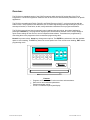
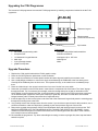
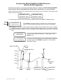
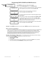
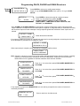
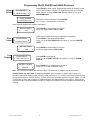
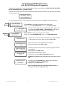
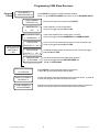
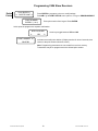
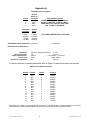
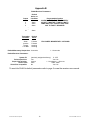
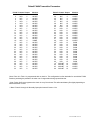
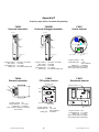
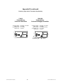
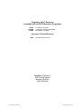
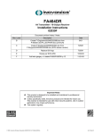
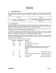
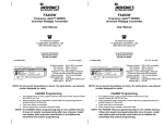
FA104
C104 Programmer Upgrade
User Manual
for FA416, FA416D, FA464
Frequency Agile™ Receivers
and
C404 4-channel slave receiver
© 1994 INOVONICS Corporation
LIT-FA104-USER 14-Nov-95
Table of Contents
Overview................................................Page 1
Upgrading the C104..............................Page 2
Programming FA416 & FA464 .............Page 3
Point Status ................................Page 3
Receiver Setup ...........................Page 4
Output Setup ..............................Page 5
Program Points ..........................Page 6
Delete Points ..............................Page 7
Clear Faults ................................Page 7
Test Outputs...............................Page 7
Programming C404...............................Page 8
Point Status ................................Page 8
Receiver Setup ...........................Page 8
Program Points ..........................Page 9
Delete Points ..............................Page10
Appendix A: FA416 defaults ................Page 11
Appendix B: FA464 defaults ................Pages 12-13
Appendix C: C404 defaults ..................Page 14
Appendix D: Recommended transmitter
programming..................Pages 15-16
© 1994 INOVONICS Corporation
LIT-FA104-USER 14-Nov-95
Overview:
The FA104 is an upgraded version of the C104 Programmer which has the full functionality of the FA116
Programmer. The FA104 Programmer allows the user to alter receiver and transmitter parameters to fit specific
applications.
The FA104 is compatible with FA416, FA416D, and FA464 Frequency Agile™ receivers as well as with the
C404 receiver. The programmer also allows the user to monitor signal margin and signal strength of points, to
test output functions, to clear faults, to add, modify and delete transmitters and to program transmitters.
The FA104 is menu-driven. Users locate main menu headings using arrow keys, then select headings by
pressing the ENTER key. The programmer displays option screens which allow the user to accept, change or
reject current settings for the receiver, receiver outputs and transmitters. Transmitters are programmed by
connecting them to the programmer via the transmitter programming cable.
Numeric keys enter values. Arrow keys change menu options. The ENTER key advances to the next available
option or menu heading. The EXIT key leaves the current option level. From a main menu heading, EXIT leaves
programming mode.
EXIT
A
B
ENTER
•
•
•
•
© 1994 INOVONICS Corporation
0
1
2
3
4
5
6
7
8
9
POWER
FA104 PROGRAMMER
Features
Programs all FA-series and C-series receivers and transmitters.
Sets receiver and transmitter parameters.
Permits transmitter zoning.
2-Line x 16-character liquid crystal display.
1
LIT-FA104-USER 14-Nov-95
Upgrading the C104 Programmer
The Inovonics C104 programmer becomes the FA104 programmer by installing components included in the the F104
upgrade kit.
Elastomer keypad
Microprocessor
(Orient notch as shown)
3-pin header
Contents of the kit:
1
1
1
3
1
1
Tools needed:
transmitter programmming cable
microprocessor
1x3 elastomeric keypad element
blank keys
3-pin right-angle header
graphic overlay label
small (#1 or #0) phillips head screwdriver
small slot screwdriver
small paper clip or .032" wire
soldering iron
solder
Upgrade Procedure:
1.
2.
3.
4.
5.
6.
7.
8.
9.
10.
Replace the C104 graphic label with the FA104 graphic overlay.
Place the C104 Programmer upside down on the workbench.
Use a small slot screwdriver to release plastic catches at bottom edge and carefully remove back cover.
Use a small phillips screwdriver to remove the single screw fastening the PCB board to the front hosing cover.
Carefully lift the PCB away from the front cover. This exposes the keys, so be careful not to accidentally dump
them.
Place the 3 blank keys in the unused cutouts in the front cover. Set the front cover aside.
Solder the 3-pin header on the PCB as shown. Insert from the component side of the board. The "short" legs go
through the board. Tip: for maximum joint strength, solder the through-hole pins on pads on both sides of the
board. Solder on the component side first, to tack the header in place, then turn the PCB over and put good joints
on the backside pads. Inspect the solder joints carefully for good flow, and make sure that there are no solder
bridges between pads. Finished joints should look "bright and shiny".
Insert the paper clip or wire into the holes on the front side of the elastomeric keypad and press the mounting pegs
through the mounting holes in the PCB.
Very carefully remove the microprocessor from the socket. If you don't have a special tool for this procedure, use a
small flat screwdriver under the chip body to gradually pry the microprocessor legs out of the socket.
Remove the upgrade microprocessor from the anti-electrostatic foam and carefully insert it into the socket. THE
MICRO IS ORIENTED WITH THE POLARIZING NOTCH TOWARD THE CENTER OF THE BOARD. A good
method is to insert all the pins on one side of the socket, then to carefully press the other side in. After insertion,
look closely for bent or buckled leads.
Re-assemble the programmer. Tip: when assembling the housing, hook the top hinges first, then snap the bottom
latches into place.
© 1994 INOVONICS Corporation
2
LIT-FA104-USER 14-Nov-95
Programming FA416, FA416D and FA464 Receivers
with the FA104 Programmer
Following are descriptions of menu and option displays. Main menu headings are POINT STATUS, RECEIVER
SETUP, OUTPUT SETUP, PROGRAM POINT, DELETE POINT, CLEAR FAULTS and TEST OUTPUTS.
When the FA104 is first powered up, the display briefly shows software version information, then shows the logo
display, including receiver type:
INOVONICS FA416
INOVONICS FA464
FREQUENCY AGILE
FREQUENCY AGILE
To enter programming mode, enter the access code. Default access code is 3446. The display will show:
Point
Status
Press ENTER for
Press ENTER to see signal margins, signal levels and current point status.
Press ! to go to Receiver Setup menu or press " to go to Test Outputs.
! POINT STATUS "
Signal margin is an indicator of relative signal strength to background noise. Margin values are from 3 (signal
just distinguishable from background) to 33 (strongest). Signal margins below 10 are reported as "Weak".
Signal level is an absolute measure of intensity, ranging from about -65dB (very strong) to below -110dB (very
faint).
!1 ALM TMP BATT"
GOOD SIGNAL
The top line of the display shows the current status of the transmitter.
The second line will read "Good Signal" or "Weak Signal". Press
ENTER to view
!1 ALM TMP BATT"
LVL:-nnn MAR:+mm
The top line of the display shows the current status of the transmitter.
The bottom line shows real-time values in dB and dBm for signal level
and signal margin. Press ENTER to toggle back to "Good Signal /
Weak Signal" display.
`
Received
Signal
Signal Level (dB)
33
Signal Margin Scale
33
-65dB
33
-75dB
-85dB
3
-95dB
3
-105dB
Background
Noise
3
-115dB
© 1994 INOVONICS Corporation
33
10
-65dB
-100dB
3
Not Received
18
Not Received -75dB
Signal Margin
Signal Level
LIT-FA104-USER 14-Nov-95
Programming FA416, FA416D and FA464 Receivers
Receiver
Setup
Press ENTER for
Press ENTER to review or to modify receiver settings.
Press ! to go to Output Setup menu or " for Review Points.
! RCVR SETUP "
System ID is encoded in all data transmissions to identify transmitters
to their respective receivers. Enter a code from 000 to 255.
SYSTEM ID: 123
SUPERVISE POINTS
!
YES
"
MAX TX INACTIVE
TIME: 4 !
MIN "
3446
VISION COMPATIBLE
NO
How long should the receiver wait for a supervisory signal to declare
points inactive?
Enter value from 1 to 99. Arrow keys toggle between MIN and HRS.
To change dealer access code enter number from 0000 to 9999.
(3446 is default.) Note: Default access code may be reset ONLY by
restoring receiver to factory defaults. See below.
ACCESS CODE
!
Should the receiver monitor transmitters for inactivity?
Arrow keys toggle between YES and NO.
"
Should the receiver look for transmitter data for Vision Plus systems?
Arrow keys toggle between YES and NO.
Reminder: Press ENTER to advance to next menu option. ENTER accepts data in display and proceeds.
What is "Vision Plus Compatibility"?
Vision Plus Compatibility permits transmitters programmed by a the Vision Plus panel to be monitored by an
FA416, FA416D or an FA464 receiver AS LONG AS BOTH SYSTEMS HAVE THE SAME SYSTEM
ID.Transmitters monitored by FA receivers need not be programmed by the receiver. Once the receiver
hears a Vision Plus-programmed transmitter, the receiver will consider it one of its own. (Note: any
transmitters programmed by an FA416 receiver will NOT be received by a Vision Plus .)
Resetting FA416, FA416D or FA464 receivers: The following sequence will restore the receiver to factory
default settings: (ADV, RESET and DEL Buttons are located on the receiver.)
1. Press and Hold ADV.
2. Press and release RESET.
3. Release ADV.
4. Immediately, while the Decode and Valid LEDs are off, press and hold DEL for 6 to 7 seconds.
5. The receiver will flash the TX PRGM LED, indicating restoral complete.
© 1994 INOVONICS Corporation
4
LIT-FA104-USER 14-Nov-95
Programming FA416, FA416D and FA464 Receivers
Output
Setup
Press ENTER for
! OUTPUT SETUP "
Press ENTER to review or to modify output settings.
Press ! to go to PROGRAM POINTS menu option or " to go to RCVR
SETUP.
Press ENTER to advance through all numbered outputs.
Press ! or "to select from options ALARM,
ALARM+TAMPER, TAMPER, LO BATT, INACTVE,
TAMP+LOBATT, TAMP+INACTVE, BATT+INACTVE, ANY
TX FAULT, and DISABLED.
OUTPUT nn:
!
ALARM
"
Note: ALARM and ALARM+TAMPER are point-specific: points programmed to a given output will trip the
output if alarmed or if tampered. All other fault options are global; i.e., any listed fault (or combination of faults)
will cause the output to activate. Attempts to assign duplicate global fault conditions to other outputs are not
allowed.
OUTPUT 1: GLOBL
Global faults will be indicated.
! TAMP+LO BATT "
If an output is modified to function as a global fault output and is currently assigned to an active point, the user
will be prompted for permission to re-assign the output:
OUTPUT 1 IN USE
REASSIGN?! YES "
When output setup is complete, points affected by re-assignment will be shown.
CHECK POINT
1
OUTPUT ASSIGNM'T
Note: "Follower" outputs go on and off as the transmitter changes between alarm and secure states. "Latching"
outputs go on at first activation, and stay on until reset. "Momentary" outputs go on for a prescribed
duration then turn off, regardless of what the transmitter does after first activation.
ALARM OUTPUTS
!
FOLLOWER
"
Press ! or " to select from options FOLLOWER, MOMENTARY or
LATCHING.
"
Press ! or " to select from options FOLLOWER, MOMENTARY or
LATCHING.
TAMPER OUTPUT
!
FOLLOWER
LO BATT OUTPUT
!
LATCHING
"
INACTIVE OUTPUT
!
FOLLOWER
"
Press ! or " to select from options FOLLOWER, MOMENTARY or
LATCHING.
Press ! or " to select from options FOLLOWER, MOMENTARY or
LATCHING.
If any outputs are programmed MOMENTARY, the user will be prompted for the number of seconds of
momentary activation.
MOMENTARY OUTPUT
TIME:
© 1994 INOVONICS Corporation
Enter a value from 1 to 16 seconds.
4 secs
5
LIT-FA104-USER 14-Nov-95
Programming FA416, FA416D and FA464 Receivers
Program
Points
Press ENTER to
!PROGRAM POINT"
POINT NUMBER:
ENTER #(1 to nn)
EXT SWITCH TYPE
! NORM/OPEN "
END OF LINE
RESISTOR: ! NO "
USE INTERNAL
CONTACT: ! NO "
CHECK-IN TIME
! 60 SECONDS "
OUTPUT TO USE:
! OUTPUT 1 "
Press ENTER to program a point or to modify settings.
Press ! to go to DELETE POINTS menu option or " to go to OUTPUT SETUP.
Enter point number from keypad. Press ENTER.
(Note: nn=16 or nn=64, depending on receiver.)
Is the external transmitter switch loop Normally Open or Closed?
Arrow keys toggle between N/O and N/C.
Is a 2.2K end of line resistor being used?
Arrow keys toggle between YES and NO.
Is the FA200W widegap magnet contact being used?
Arrow keys toggle between YES and NO.
How often should transmitters send supervisory data?
Arrow keys toggle between UNSUPERVISED,
10, 30, or 60 SECONDS and 5, 30 or 60 MINUTES.
Which output should this point activate?
Arrow keys select desired output.
If the selected output has been previously assigned as a global fault output, the programmer will prompt for
confirmation:
It is recommended that the output be redefined as an alarm, or
OUTPUT n GLOBAL
that the point be assigned to another output. Arrow keys toggle
CONFIRM?! YES "
between YES and NO.
ENTER TO PROGRAM
Press ENTER to proceed with transmitter programming.
or press A to go through transmitter options again.
"A" to REVIEW
CONNECT TX+RESET
OR PRESS "A"
Connect transmitter and press transmitter reset to program device, or press
A to save program information, activate the point and select a new point
number, or press EXIT to save program information without activating the
point. One of the following displays will appear:
If a transmitter is connected, display indicates successful transmitter
programming sequence. Display remains for about 3 seconds, then
returns to the point number selection screen.
POINT NUMBER nn
TX PROGRAMMED
If special key A is pressed, the point is saved and activated, even
though no transmitter has been programmed. This may be
necessary when replacing receivers or when using the FA100.
POINT NUMBER nn
POINT ACTIVATED
If EXIT is pressed, point program information is saved without
activating the point.
POINT NUMBER nn
PROGRAM SAVED
© 1994 INOVONICS Corporation
6
LIT-FA104-USER 14-Nov-95
Programming FA416, FA416D and FA464 Receivers
Delete
Points
Press ENTER to delete a point. Programming remains in memory, but the
receiver will not look for the point. To reactivate the point, go to Program
Points. Press ! to go to CLEAR FAULTS menu option or " to go to
PROGRAM POINT.
Press ENTER to
! DELETE POINT "
POINT NUMBER:
Enter point number from keypad. Press ENTER.
(nn = 16 or nn = 64, depending on receiver.)
ENTER #(1 to nn)
At this point the programmer requests confirmation:
ARE YOU SURE?
!
Clear
Faults
NO
"
Faults may be registered during programming and operation.
Press ENTER to clear latched fault outputs.
Press ! to go to TEST OUTPUTS menu option or " to go to DELETE
POINT.
Press ENTER to
! CLEAR FAULTS "
ARE YOU SURE?
!
Test
Outputs
YES
"
Press ENTER to
ENTER to TOGGLE
OUTPUT 1
Press ENTER to accept answer in next line.
Arrow keys toggle between YES and NO.
Press ENTER to test outputs.
Press ! to go to POINT STATUS menu option or " to go to CLEAR
FAULTS.
! TEST OUTPUTS "
!
Press ENTER to accept answer in next line.
Arrow keys toggle between NO and YES.
"
Press ENTER to turn selected output on and off.
Press ! or " to select a different output.
Note: The FA416 has 4 outputs, plus the fault output. The FA464 has 16 outputs, plus the fault output.
Creating Zones with the FA104: By assigning transmitter alarm conditions to specific alarm outputs, it is
possible to differentiate between types of alarms, areas of alarms, etc. For example, suppose an application in a
small business requires 10 holdup buttons, 1 fire exit door and 3 removable pendants. Program outputs 1, 2 and
3 to be active on alarm and program the FA200s attached to the holdup buttons to use output 1. Assign the fire
exit point to output 2 and the pendants to output 3. Configure the system to monitor low batteries and tampers at
output 4.
© 1994 INOVONICS Corporation
7
LIT-FA104-USER 14-Nov-95
Programming C404 Slave Receivers
with the FA104 Executive Programmer
Following are descriptions of menu and option displays. Main menu headings are POINT STATUS, RECEIVER
SETUP, PROGRAM POINT, and DELETE POINT.
When the FA104 is first powered up, the display briefly shows software information, then shows the logo display,
including receiver type.
INOVONICS C404
SLAVE RECEIVER
To enter programming mode, enter the access code. Default access code is 0000. The display will show:
Point
Status
Press ENTER for
! POINT STATUS "
Press ENTER to see signal strength and current point status.
Press ! to go to RECEIVER SETUP menu or " for DELETE POINT.
!#1: ALM TMP B "
GOOD SIGNAL (-nn)
Receiver
Setup
Press ENTER for
! RCVR SETUP "
The first line shows point status, including a low battery symbol. The
value beside the GOOD SIGNAL or WEAK SIGNAL is dBm above
receiver threshold level, from -99 (weak) to -65 (strong).
Press ENTER to review or to modify receiver settings.
Press ! to go to PROGRAM POINT menu or " for REVIEW POINTS.
System ID is encoded in all data transmissions to identify transmitters
to their respective receivers. Enter a code from 000 to 255.
SYSTEM ID: 123
SUPERVISE POINTS
!
YES
"
MAX TX INACTIVE
TIME: 60 MINUTES
Should the receiver monitor transmitters for inactivity?
Arrow keys toggle between YES and NO.
How long should the receiver wait for a supervisory signal to declare
points inactive?
Enter value from 1 to 254 minutes.
Change dealer access code, if desired.
Enter access code from 0000 to 9999. (0000 is default.)
ACCESS CODE
0000
WARNING:The C404 access code cannot be recovered or reset if
lost.
ALARM OUTPUTS :
!
FOLLOWER
"
Set mode of all C404 ALARM outputs. Arrow keys select option:
FOLLOWER, LATCHING or MOMENTARY.
Press ! or " to change option.
Note: This setting affects all of the C404's alarm outputs. The
C404 global fault output is always latching.
© 1994 INOVONICS Corporation
8
LIT-FA104-USER 14-Nov-95
Programming C404 Slave Receivers
Program
Points
Press ENTER to
Press ENTER to program or modify transmitter settings.
Press ! to go to DELETE POINTS menu option or " for RECEIVER SETUP.
! PROGRAM POINT"
POINT NUMBER:
ENTER #(1 to 4)
4-BUTTON TX:
!
YES
"
EXT SWITCH TYPE
! NORM/OPEN "
END OF LINE
THESE OPTIONS
ARE SKIPPED IF
4-BUTTON TX
= "YES"
RESISTOR: ! NO "
USE INTERNAL
CONTACT: ! NO "
CHECK-IN TIME
! 60 SECONDS "
ENTER TO PROGRAM
"A" to REVIEW
RESET TX +CONNECT
OR PRESS "A"
POINT NUMBER nn
Tx PROGRAMMED
© 1994 INOVONICS Corporation
Enter point number from keypad. Press ENTER.
Is the transmitter a C100 Commander?
Arrow keys toggle between YES and NO.
Is the external switch loop normally open or closed?
Arrow keys toggle between NORM/OPEN and NORM/CLOSED.
Is a 2.2K end of line resistor being used to monitor the switch loop?
Arrow keys toggle between NO and YES.
Is C200W widegap magnet contact being used? Arrow keys toggle
between NO and YES.
How often should supervisory data be transmitted?
Arrow keys toggle between UNSUPERVISED and
10, 30, or 60 SECONDS.
Press ENTER to proceed with transmitter programming,
or press A to go through transmitter options again.
Connect transmitter and press transmitter reset to program device, or press A
to save point program and select a new point number.
Indicates successful transmitter programming sequence. Display remains for
about 3 seconds, then returns to the point number selection screen.
9
LIT-FA104-USER 14-Nov-95
Programming C404 Slave Receivers
Delete
Points
Press ENTER to
!#DELETE POINT "
Press ENTER to program a point or to modify settings.
Press ! to go to POINT STATUS menu option or " to go to PROGRAM POINT.
POINT NUMBER:
ENTER # (1 to 4)
Enter point number from keypad. Press ENTER.
At this point the programmer requests confirmation:
ARE YOU SURE?
!###YES
POINT NUMBER: nn
DELETED
"
Arrow keys toggle between YES and NO.
Indicates successful point deletion. (Display remains for about 3 seconds, then
returns to the point number selection screen.)
Note: Programming parameters are not erased from receiver memory.
Transmitters may be re-programmed to the deleted point number.
© 1994 INOVONICS Corporation
10
LIT-FA104-USER 14-Nov-95
Appendix A
FA416 Receiver Parameters
Output
1
2
3
4
Default
Active on
Condition
Alarm
Alarm
Alarm
Alarm
Transmitter
Condition
Default
Mode
Alarm
Inactive
Tamper
Low Batt
Follower
Follower
Latching
Latching
Programmable Options
ALARM / ALARM+TAMPER / TAMPER /
LO BATT / INACTIVE / TAMP+LO BATT /
TAMP+INACTIVE / LO BATT+INACTIVE /
ANY TX FAULT / DISABLED
FOLLOWER / MOMENTARY / LATCHING
Default Momentary Output time: 4 seconds
1 - 16 seconds
Default Receiver Parameters:
System ID:
Point supervision:
Supervision window:
Access code:
Vision Plus compatible:
(randomly assigned at factory)
0 - 255
Yes
Yes / No
4 hours
1 - 99 minutes, 1 - 99 hours
3446
0000 - 9999
No
Yes / No
To reset a receiver to default parameters refer to Page 5 or see the receiver user manual.
Default Transmitter Parameters
Point # Contact
1
N/O
2
N/O
3
N/C
4
N/C
5
N/O
6
N/O
7
N/O
8
N/O
9
N/C
10
N/C
11
N/C
12
N/C
13
N/C
14
N/C
15
N/C
16
N/O
Output
1
2
3
4
1
2
3
4
1
2
3
4
1
2
3
4
Check-in
60 SEC
60 SEC
60 SEC
60 SEC
60 SEC
60 SEC
60 SEC
60 SEC
60 SEC
60 SEC
60 SEC
60 SEC
60 SEC
60 SEC
60 SEC
NONE
Note: Point 16 in Table 1 is programmed with no check-in. This configuration is often desirable for use with the
FA204 Pendant, permitting the pendant to be taken out of range without being reported inactive.
© 1994 INOVONICS Corporation
11
LIT-FA104-USER 14-Nov-95
Appendix B
FA464 Receiver Parameters
Output
1
2
3
4
...
...
16
Default
Active on
Condition
Alarm
Alarm
Alarm
Alarm
Programmable Options
ALARM / ALARM+TAMPER / TAMPER /
LO BATT / INACTIVE / TAMP+LO BATT /
TAMP+INACTIVE / LO BATT+INACTIVE /
ANY TX FAULT / DISABLED
Alarm
Transmitter
Condition
Default
Mode
Alarm
Inactive
Tamper
Low Batt
Follower
Follower
Latching
Latching
FOLLOWER / MOMENTARY / LATCHING
Default Momentary Output time: 4 seconds
1 - 16 seconds
Default Receiver Parameters:
System ID:
Point supervision:
Supervision window:
Access code:
Vision Plus compatible:
(randomly assigned at factory)
0 - 255
Yes
Yes / No
4 hours
1 - 99 minutes, 1 - 99 hours
3446
0000 - 9999
No
Yes / No
To reset the FA464 to default parameters refer to page 5 or see the receiver user manual.
© 1994 INOVONICS Corporation
12
LIT-FA104-USER 14-Nov-95
Default FA464 Transmitter Parameters
Point# Contact Output
1
N/O
1
2
N/O
2
3
N/C
3
4
N/C
4
5
N/O
1
6
N/O
2
7
N/O
3
8
N/O
4
9
N/C
1
10
N/C
2
11
N/C
3
12
N/C
4
13
N/C
1
14
N/C
2
15
N/C
3
16*
N/C
4
17
N/C
5
18
N/C
5
19
N/C
5
20
N/C
5
21
N/C
6
22
N/C
6
23
N/C
6
24
N/C
6
25
N/C
7
26
N/C
7
27
N/C
7
28
N/C
7
29
N/C
8
30
N/C
8
31
N/C
8
32
N/C
8
Check-In
60 SEC
60 SEC
60 SEC
60 SEC
60 SEC
60 SEC
60 SEC
60 SEC
60 SEC
60 SEC
60 SEC
60 SEC
60 SEC
60 SEC
60 SEC
NONE
60 SEC
60 SEC
60 SEC
60 SEC
60 SEC
60 SEC
60 SEC
60 SEC
60 SEC
60 SEC
60 SEC
60 SEC
60 SEC
60 SEC
60 SEC
60 SEC
Point#
33
34
35
36
37
38
39
40
41
42
43
44
45
46
47
48
**
49
50
51
52
53
54
55
56
57
58
59
60
***
61
62
63
64
Contact Output
N/C
9
N/C
9
N/C
9
N/C
9
N/C
10
N/C
10
N/C
10
N/O
10
N/O
11
N/O
11
N/O
11
N/O
11
N/O
12
N/O
12
N/O
12
N/O
12
N/O
13
N/O
13
N/O
13
N/O
13
N/O
14
N/O
14
N/O
14
N/O
14
N/O
15
N/O
15
N/O
15
N/O
15
N/O+INT
16
N/O+INT
16
N/O+INT
16
N/O+INT
16
Check-In
60 SEC
60 SEC
60 SEC
60 SEC
60 SEC
60 SEC
60 SEC
60 SEC
60 SEC
60 SEC
60 SEC
60 SEC
60 SEC
60 SEC
60 SEC
60 SEC
5 MIN
5 MIN
5 MIN
5 MIN
5 MIN
5 MIN
5 MIN
5 MIN
5 MIN
5 MIN
5 MIN
5 MIN
60 SEC
60 SEC
60 SEC
60 SEC
*Note: Point 16 in Table 1 is programmed with no check-in. This configuration is often desirable for use with the FA204
Pendant, permitting the pendant to be taken out of range without being reported Inactive.
**Note: Points 49-60 are programmed to check in every five minutes.This will extend battery life slightly depending on
which transmitter is used.
***Note: Points 61 through 64: Normally Open plus Internal Contact = Yes.
© 1994 INOVONICS Corporation
13
LIT-FA104-USER 14-Nov-95
Appendix C
C404 4-channel Slave Receiver Parameters
Output
1
2
3
4
Default
Active on
Condition
Alarm
Alarm
Alarm
Alarm
Programmable Options
Not programmable
"
"
"
Note: C404 outputs cannot be re-assigned to other points.
Transmitter
Condition
Default
Mode
Follower / Momentary / Latching
Alarm
Follower
Global Fault Latching (Not programmable) Latching only
Default Momentary Output time: 2 seconds
Default Receiver Parameters:
System ID:
Point supervision:
Supervision window:
Access code:
(randomly assigned at factory)
0 - 255
Yes
Yes / No
240 minutes
0 - 240 minutes
0000
0000 - 9999
NOTE: The C404 cannot be reset to default conditions. It must be reprogrammed.
Default Transmitter Parameters
Default
Transmitter type
Programmable Options
Standard
STANDARD
4-BUTTON TX (C100 REMOTE)
Point 1: N/O
Point 2: N/O
Point 3: N/C
Point 4: N/C
NORMALLY OPEN / NORMALLY CLOSED
NORMALLY OPEN / NORMALLY CLOSED
NORMALLY OPEN / NORMALLY CLOSED
NORMALLY OPEN / NORMALLY CLOSED
End of Line Resistor
No
NO / YES
Internal Contact
(C200W widegap magnet loop)
No
NO / YES
60 Seconds
60 SECONDS
30 SECONDS
10 SECONDS
NONE
Contacts
Check-In period
© 1994 INOVONICS Corporation
14
LIT-FA104-USER 14-Nov-95
Appendix D
Frequency Agile Series Transmitter Programming
FA200
Universal transmitter
FA200W
Universal widegap transmitter
Reset button
Reset button
Programming
header
B attery
Battery
Tamper switch
Programming
header
Widegap
reed switch
Tamper switch
Battery terminals
Program contacts:
EOL resistor:
Typical battery life:
Battery type:
FA201
Smoke detector
N/O or N/C, as needed
as needed
2 to 4 years
4.5V alkaline battery pack
FA204
Pendant transmitter
Battery terminals
Program contacts:
EOL resistor:
Internal contact:
Typical battery life:
Battery type:
N/O or N/C, as needed
as needed
as needed
2 to 4 years
4.5V alkaline battery pack
FA206
PIR motion detector
Programming header
Programming
header
Reset button
Program contacts:
Typical battery life:
N/O
1 year
(with 2 batteries)
Battery type:
9V alkaline
Notes: Remove jumper to program,
replace jumper after programming.
FA207
Glassbreak detector
Programming Header
Reset
Reset
Programming
+
header
Battery
+
3.0VDC
Lithium
3.5V
1-zone or 2-zone
detection header
Program contacts: N/O
Typical battery life: 2 to 3 years
Battery type: 3.5V lithium
Note: The FA204 is always supervised
for low battery.
Tamper switch
Optional battery
Program contacts:
Typical battery life:
Battery type:
© 1994 INOVONICS Corporation
15
N/C
1 to 3 years
(with 2 batteries)
3.5V lithium
Reset button
Program contacts: N/O
Typical battery life: 2 to 4 years
Battery type: 3V lithium
Notes: Remove jumper to program,
replace jumper after programming.
LIT-FA104-USER 14-Nov-95
Appendix D (continued)
Frequency Agile Series Transmitter Programming
FA210
Reduced-size
Universal transmitter
Program contacts:
EOL resistor:
Typical battery life:
Battery type:
N/O or N/C, as needed
as needed
2 to 4 years
3V lithium
+
FA210W
Reduced-size
Universal widegap transmitter
Program contacts:
EOL resistor:
Internal contact:
Typical battery life:
Battery type:
+
3.0V
FA210W Widegap
Reed switches
© 1994 INOVONICS Corporation
N/O or N/C, as needed
as needed
as needed (FA210W)
2 to 4 years
3V lithium
16
3.0V
Raised key
indicator
LIT-FA104-USER 14-Nov-95
NOTES
© 1994 INOVONICS Corporation
17
LIT-FA104-USER 14-Nov-95
Frequency Agile™ Receivers
compatible with the FA104 Executive Programmer
FA416
FA416D
FA464
16-channel / 4-output
16-channel / 4-output with display
64-channel / 16-output
Inovonics C-series Receivers
C404
4-channel slave receiver
Inovonics Corporation
2100 Central Avenue
Boulder CO 80301
(800) 782-2709
© 1994 INOVONICS Corporation
LIT-FA104-USER 14-Nov-95