1
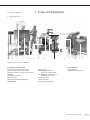
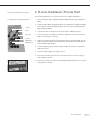
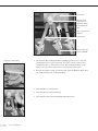
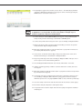
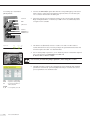
Process Example
Buffer Preparation with FlexAct® BP
85032-539-69
Ver. 04 | 2011
Contents
Legal Notices | Impressum . . . . . . . . . . . . . . . . . . . . . . . . . . . . . . . . . . . . . . . . . . . . Page 2
English . . . . . . . . . . . . . . . . . . . . . . . . . . . . . . . . . . . . . . . . . . . . . . . . . . . . . . . . . . . . . Page 3
Fig. Front cover: FlexAct® BP COM
Sartorius Stedim Biotech GmbH
Technical Documentation | Technische Dokumentation
August-Spindler-Strasse 11
D-37079 Goettingen
Germany | Deutschland
Internet: www.sartorius-stedim.com
E-mail: [email protected]
Printed in Germany on chlorine-free paper.
If you require mandatory information regarding specific properties of your
FlexAct® COM that goes beyond that which is described here, please contact us.
No part of this publication may be reprinted, reproduced or translated in any
form or by any means without the prior written permission of
Sartorius Stedim Biotech GmbH.
FlexAct® is a registered trademark of Sartorius Stedim Biotech GmbH
2
Contents
Contents
Introduction . . . . . . . . . . . . . . . . . . . . . . . . . . . . . . . . . . . . . . . . . . . . . . . . . . . . . . . . . . .
I.
Introduction . . . . . . . . . . . . . . . . . . . . . . . . . . . . . . . . . . . . . . . . . . . . . . . . . . .
II.
Abbreviations . . . . . . . . . . . . . . . . . . . . . . . . . . . . . . . . . . . . . . . . . . . . . . . . . .
III. Definitions . . . . . . . . . . . . . . . . . . . . . . . . . . . . . . . . . . . . . . . . . . . . . . . . . . . .
IV. Operating Instructions | Document Structure . . . . . . . . . . . . . . . . . . . . . . . .
V.
Explanation of Symbols . . . . . . . . . . . . . . . . . . . . . . . . . . . . . . . . . . . . . . . . . .
VI. Safety Instructions . . . . . . . . . . . . . . . . . . . . . . . . . . . . . . . . . . . . . . . . . . . . . .
4
4
4
5
5
6
6
1. Setup and Equipment . . . . . . . . . . . . . . . . . . . . . . . . . . . . . . . . . . . . . . . . . . . . . . . 9
1.1 System Overview . . . . . . . . . . . . . . . . . . . . . . . . . . . . . . . . . . . . . . . . . . . . . . . 9
1.2 Hardware . . . . . . . . . . . . . . . . . . . . . . . . . . . . . . . . . . . . . . . . . . . . . . . . . . . . . 10
1.3 Single Used . . . . . . . . . . . . . . . . . . . . . . . . . . . . . . . . . . . . . . . . . . . . . . . . . . . . 10
1.4 Customer . . . . . . . . . . . . . . . . . . . . . . . . . . . . . . . . . . . . . . . . . . . . . . . . . . . . . 10
2. Process Installation | Process Start . . . . . . . . . . . . . . . . . . . . . . . . . . . . . . . . . . . . 11
2.1 Setting up of the mixing system . . . . . . . . . . . . . . . . . . . . . . . . . . . . . . . . . . 11
2.2 Filling of mixing bag and powder addition . . . . . . . . . . . . . . . . . . . . . . . . . . 12
2.3 Setting-up of automated pH-adjustment . . . . . . . . . . . . . . . . . . . . . . . . . . . 14
2.4 Run the automated pH adjustment process . . . . . . . . . . . . . . . . . . . . . . . . . 15
2.5 Setting up of the receiving bag and filter for filtration . . . . . . . . . . . . . . . 16
2.6 Running the filtration . . . . . . . . . . . . . . . . . . . . . . . . . . . . . . . . . . . . . . . . . . . 17
3. Ending the Process . . . . . . . . . . . . . . . . . . . . . . . . . . . . . . . . . . . . . . . . . . . . . . . . . . 19
Contents
3
Introduction
I. Instruction
Introduction
The FlexAct® BP is a standardized configurable disposable solution (CDS) dedicated
to buffer preparation in biopharmaceutical processes. The FlexAct® BP addresses the
entire development cycle and production capacity needs from 50 to 1,000L for buffer
preparation. The integration of monitoring & control features for pH, temperature,
pressure, pump speed and fluid level control is a further milestone for the implementation of process relevant single use equipment. The integrated control allows endusers to perform other tasks during the buffer preparation operation. Combined with
a Flexel® for Magnetic Mixer1) and Palletank® the multifunctional Central Operating
Module enables the user to install, operate and monitor a fully single use unit
operation.
This document describes different models and equipment of FlexAct® COM that were
available at the time of its creation. The equipment supplied with a device does not
necessarily cover every possible type of equipment; some may differ from the description while others may contain additional equipment. The descriptions for the fittings
can differ from the ones in the related P&I diagram and the equipment list because
these documents are each adapted to the customer’s specific requirements.
Documentation on customer-specific designs and equipment can be separately
supplied or are available on request.
Sartorius Stedim Biotech GmbH
Customer Service
August-Spindler-Strasse 11
37079 Goettingen, Germany
Phone +49.551.308.3318
Fax +49.551.308.3755
www.sartorius-stedim.com
II. Abbreviations BI Basic Issue
BP
CDS
COM
DCU
l/L
MP
P&I
SSB
1)
4
Introduction
Buffer Preparation
Configurable Disposable Solution
Central Operating Module
FlexAct® Sartorius Stedim Measurement and Control System
Liter
Media Preparation
Diagram Piping & Instrumentation Diagram
Sartorius Stedim Biotech
This product uses ATMI patented Magnetic Mixer technology!
III. Definitions
IV. Operating Instructions|
Intended Use
FlexAct® COM
FlexAct® COM ready-to-connect system with
– Trolley,
– DCU microbox
– Touch-screen
– Pump
– Filter holder | Drip tray
– Pump head supporting plate
and
– PT100 temperature sensor
Setup and Equipment
Description of all component steps required to set up
FlexAct® BP | components which have to be supplied by the
customer.
Process Installation |
Process Start
Description of all steps required to start a process.
Process Capability Time at which the actual process, for
example buffer preparation or virus inactivation, can be
started. Process capability is reached when the initial
operations are setup to completion.
FlexAct® BP COM may only be used with equipment and under operating
conditions described in the present equipment documentation. FlexAct® COM is
basically a work platform. It accommodates all accessory parts necessary for
transferring media within biotechnological applications.
Users must be qualified to handle the system and the process-relevant media and be
aware of the hazards potentially associated with the process. Some processes may
require that FlexAct® or the workplace be equipped with additional safety features or
that precautions be otherwise taken to protect personnel and working environment.
Additional, the operator has to follow all of the contry-specific safety-laws and -rules!
Safety and warning instructions given in this document only apply to the devices and
supplement the rules and regulations the operator stipulates at the workplace for the
respective process.
© Sartorius Stedim Biotech GmbH. No guarantee is assumed for the information provided. Sartorius
reserves the right to make technical changes to the equipment or changes to this document without any
prior notice. No part of this document may be changed, or reproduced, nor is any other use permitted
without obtaining prior written permission.
Introduction
5
V. Explanation of Symbols
The “Warning” symbol and this formatting indicate hazards that can be
expected with a high probability and can lead to severe injuries.
The “Caution” symbol and this formatting indicate hazards that can occur
and can lead to severe injuries if the notes and instructions are not observed.
This warning indicates risks that can lead to material damage.
Instructions and notes labeled with this symbol indicate steps that must be
performed with particular care, or point to other especially important aspects
to be observed.
VI. Safety Instructions
y
The box indicates other important information.
1., 2., ...
Numbered paragraphs indicate steps that should be performed consecutively in the
order listed.
t
This symbol points to information referenced in another section.
Organizational measures on the part of the operator:
y The operator must point out the hazards to which personnel and the working
environment may be subject during the process, must provide the suitable safety
equipment, and must publish the stipulated safety requirements.
y Only operating personnel qualified to run the process may be employed for
working with FlexAct® BP; they must be aware of potential hazards, and be
thoroughly familiar with the handling of all devices.
y Non-authorized persons must be prohibited from working on FlexAct® BP.
If hazards are associated with the process (e.g. due to process-relevant media),
the workplace must be labeled with suitable danger symbols, e.g. “BIOHAZARD”
and it should be possible to cordon it off or quarantine it if the circumstances
require.
y The workplace must be suitable for the process, e.g. resistant to acids, bases or
media and must be easy to clean, decontaminate and disinfect if contaminated.
y In general, operators must wear suitable personal protective equipment
(e.g. work clothes, gloves, safety goggles as well as a facemask if appropriate).
Workplace Setup
Workplace and supply connections in the laboratory | production facility must meet
the requirements stipulated in the equipment specifications. All intended equipment
must be complete and free of defects and flaws.
6
Introduction
Risk of injury if energy supply lines are inadvertently activated
(e.g. power supply, water, gas inlet supplies).
Energy supply lines must be blocked or secured against inadvertent startup
whenever you:
Connect or disconnect laboratory connections or connections on the production
side.
Want to disassemble peripheral installations.
When transporting or moving FlexAct® BP components, be fully aware that you
are moving equipment with an extremely high weight.
Ensure that all necessary measures are taken (e.g. warning information, barriers,
safety gear, etc.) to prevent any danger of crushing or roll-over, and thereby
the risk of injury to persons.
When assembling the PT 100 temperature sensor, make sure that the bag
is filled and not to damage the sensor channel when inserting the sensor.
Pierced or damaged sensor channels will make the bag unusable!
1. Ensure that all supply media on the laboratory or production sides , e.g. water,
supply voltage etc., match the specifications t “P&I Diagram”.
2. The workplace must be able to carry FlexAct® COM and BP components with all
equipment and the intended peripheral devices. Observe the weight and the
space requirements t „Setup and Connection“. Use suitable transportation aids
when transporting FlexAct® BP components to the place of installation and | or
changing its location.
3. Secure all laboratory connections | connections on the production side carefully.
Use only the equipment provided or released for the device. Never make any technical
modifications, unless Sartorius Stedim Biotech GmbH has expressly confirmed that
this modification does not affect safe use.
5. Loosen | remove any transport locks.
6. Check all equipment carefully for damage. Use only flawless parts.
Getting Started
All equipment must be assembled carefully and safely.
1. Before every startup, check the assembly and connections of all equipment.
Safety equipment, e.g. the overpressure | safety valves must meet the
specifications and be installed.
2. Palletanks | bags, tubing, and fittings must be leak-tight.
Persons should only stand around the equipment for carrying out necessary
work. Barricade off the hazardous area and indicate this with signs!
If applicable, ensure that the respective minimum volumes as described in the
t “Operating Instructions Manual for LevMixer®” are not undershot
Observe the operating limits and optimal settings for the process. Only operate
FlexAct® BP using the allowable energy supplies (power supply, water or gas supplies).
Introduction
7
BIOHAZARD, hazards caused by media.
When working with hazardous materials, observe the pertinent safety
regulations and laws!
1. Adjust the measurement and control system in strict accordance with the
allowable performance data for the respective equipment t “Operating
Instructions Manual for DCU FlexAct®”.
2. Perform in-process monitoring as to whether the process parameters are
achieved as expected. Take precautions to ensure that defects or disruptions
cannot cause any hazards or damage.
After placing the tubing in the pump, always make sure to press the STOP key on
the pump.
This resets the system and is indispensable for proper functioning of the pump.
Safety at the End of Process
8
Introduction
All equipment must be assembled carefully and safely.
After concluding the process, all affected components of FlexAct® COM should be
disposed of, disinfected and cleaned in accordance with their use and as prescribed by
the respectively valid laws and regulations.
1. Setup and Equipment
1. Setup and Equipment
1.1 System Overview
10
9
13
11
8/12
5
4
15
1
2
3
6
7
16
14
Figure 1-1: Overview FlexAct® BP COM :
Components FlexAct® COM
(1) Central Operating Module COM
(2) I-Dom with pressure transmitter
(3) Main switch | Emergency-Power-Switch
(4) Pump
(5) Pumphead support
(6) Touch-Panel
(7) Filterholder MidiCaps/MaxiCaps
(8) PT100 RTD
(9) Floor scale
(10) COMBICS1 indicator
(identical for BP and MP)
(11) MagMixer® with palletank
(„Media Preparation“)
(12) SU-pH sensor
(13) Powder Bag
(14) Palletank („Storage“)
Useful accessory
(15) Sartocheck®
(16) BioWelder® | BioSealer®
FlexAct® Buffer Preparation
9
1.2 Hardware
– FlexAct® BP Central Operating Module
– Magnetic Mixer Drive Unit with toolbox
– Palletank® for Magnetic Mixer with load cells (FXC114155)
or Palletank® for Magnetic Mixing XC110821) on floor scale
– Palletank® for Storage
– 1 to 2 Watson-Marlow 520/R2 pumps
– Biosealer® (optional)
– Sartocheck® (optional
1.3 Single use
– FlexAct® BP bag assembly 4BP110B01AB11003
– FLEXEL® Bag for Magnetic Mixer 100L (PROBE pH)
– FLEXEL® 3D Bioprocessing Bag for storage 100 L with
Sartopore® 2 Gamma Midicap
– Transfer Set (TITRATION)
1.4 Customer supply
–
–
–
–
–
10
FlexAct® Buffer Preparation
pH standards (e.g. pH 4/7)
Syringe with Luer connection (sampling, pH calibration)
Acid / Base for pH correction
Media powder
WFI
2. Process Installation | Process Start
2. Process Installation | Process Start
The following equipment is to be used for the process of Buffer Preparation:
2.1 Setting up of the mixing system
1. Unpack the Flexel® Bag for Magnetic Mixer t Manual Flexel® Bag for Magnetic
Mixer.
network
2. Install the Flexel® Bags for Magnetic Mixer in the Palletank® for Magnetic Mixing
with magnetic clamp from Magnetic Mixer drive unit toolbox t Manual Flexel®
Bag for Magnetic Mixer.
RTD
3. Connect the cable of the pH electrode to the FlexAct® COM sensor panel.
pH-sensor
4. Connect the cable of the RTD to the FlexAct® COM sensor panel. Do not put the
RTD in the thermowell of the bag.
balance
WM520 base
WM520 acid
5. Calibrate the pH electrode (use pH standards and rinse with WFI finally). Use the
RTD for automatic temperature compensation during calibration t Manual pH
probe t Manual DCU FlexAct®.
6. Connect weighing signal from the Combics weighting controller to the FlexAct®
COM sensor panel.
7. Connect the WFI supply to the bag’s inlet port.
8. Close the pinch clamps on the low port except the fill line. Close the clamps of
both acid/base top ports.
9. Tare the load cell at the combics panel t Magnetic Mixer Palletank® w/ load cells
and Combics 1 Controller.
Process Installation
11
Thermowell
pH-probe with
connections for
calibration buffer
and transmission
cable
Clave connector for
sampling
2 Filling lines
Drain line (3 m) to
FlexAct® COM BP
Connections at the low port of Flexel® Bag for Magnetic Mixer (probe pH)
2.2 Filling of mixing bag
1. Fill the Flexel® Bag for Magnetic Mixer with WFI up to 80 to 95% of the final
volume. Open the 8” top port and insert the top port into the stainless steel
clamp holder. Refer to the manual of Flexel® Bag for Magnetic Mixer for the
filling of the bag and the instructions for the preparing of the buffer.
2. Remove the magnetic clamp from the bag and couple the Magnetic Mixer drive
unit under the Palletank® for Magnetic Mixer.
3. Insert the RTD in the thermowell
4. Insert the pH electrode inside the bag.
5. Start impeller rotation with the Magnetic Mixer Drive Unit.
12
Process Installation
6. The pH will be logged – like all other process values – automatically by the DCU
of FlexAct® COM and the diagram of the progress can be viewed by pressing the
TREND-button of the DCU-touchscreen.
Powders can be mixed inside the same powder bag or multiple bags can be used
if appropriate. It is also possible to transfer the powder in multiple steps to
facilitate rehydration, dispersion and dissolution.
7. Connect the 8”/4” reducer (FMA114007) to the 4” port of the powder bag and
transport the powder transfer bag to the FlexAct® COM BP system.
8. Connect the powder transfer bag onto the 4” port of the Bag for Magnetic Mixer.
9. Remove the pinch clamp from the powder Transfer Bag to transfer the powder
inside the Flexel® Bags for Magnetic Mixer.
10. Mix until complete dissolution of the powders (refer to preparation instructions
provided by individual buffer supplier).
11. If more than one Powder Transfer Bag is being used, add content of the other
Powder Transfer Bags to the Palletank for Magnetic Mixer.
12. Keep the powder bag connected to the Bag for Magnetic Mixer and open one of
the ¼” top line for air removal during dilution.
13. Tare the Magnetic Mixer Palletank® w/ load cells and Combics Controller.
14. Add the remaining quantity of WFI to reach the final buffer volume, then close
the top port.
15. Mix until complete powder dissolution (refer to preparation instructions provided
by individual buffer supplier).
16. If required, remove the powder bag by opening the 4” Triclamp connection, and
close the Bag for Magnetic Mixer with the 4” plug, gasket and union clamp to
minimize exposure. Use a 4” plug kit (FMA114179) to close as well the powder bag.
17. Close the clamp at the fill line and disconnect the fill line from the water supply.
18. Record the final pH, temperature and weights values.
19. If required retrieve a buffer sample with the Luer syringe through the needleless
sampling port.
Process Installation
13
2.3 Setting-up of automated
pH-adjustment
1. Connect the WM 520/R2 signal cable with the corresponding plug of the sensor
field. If there is a pH correction with base required connect it to the base jack,
for a correction with acid in the ACID-jack.
network
RTD
2. Select the transfer line for acid-base titration of the correct length. For Flexel
Bags for Magnetic Mixer of volumes up to 200 l a 4 m is recommended, above
a length of 5 m is suitable.
pH-sensor
balance
WM520 base
WM520 acid
MagMixer tank
Pos 1
Pos 2
acid
base
3. The Transfer set (Titration) consists of a tube of ¼” and a 8” ID in order to
realize different flow rates, necessary to adopt the system different buffers and
titrations agents. See table 1 for detailed values.
4. For 8” install pump at position 1, for ¼” install at position 2. Install the required
part of the Transfer set (TITRATION) in the WM 520.
t Manual Watson-Marlow 520/R2
It is necessary to install the pump in position 2, when using the ¼” tube.
5. The PID-controller for pH of the configuration is preconfigured with standard
parameters for buffers (± 1 pH from pKa) with an Xp of 2 %. Enter the correct
process parameters into the DCU screen.
MIN
MAX
XP
– Speed for acid pump
– Speed for base pump
– Proportional share of
PID controller
DEADB,
TI, TD – not required, set to 0
14
Process Installation
Tank size
50 l
100 l
200 l
400 l
650 l
1000 l
Length of transfer set
(TITRATION)
4m
4m
4m
5m
5m
5m
Max. pump speed 8”
1 N HCl/NaOH
20 %
40 %
80 %
–
–
–
Max. pump speed ¼”
1 N HCl/NaOH
–
–
20 %
45 %
75 %
100 %
Max. pump speed ¼”
0,1 N HCl/NaOH
%
100 %
100 %
100 %
100 %
100 %
Table 1: recommended set value for Magnetic Mixer drive unit and maximum pump speed of
WM 520 / recommended length of transfer set (TITRATION)
Pump speed
20%
40%
60%
80%
100%
Rpm WM 520 44
88
132
176
220
Flow rate 8”
80 ml/min
160 ml/min
240 ml/min
320 ml/min
400 ml/min
Flow rate ¼”
280 ml/min
560 ml/min
840 ml/min
1120 ml/min 1400 ml/min
Table 2: flow rates for ¼” and 1/8” tube in relation to different pump speeds
2.4. Run the automated pH
adjustment process
1. Start the pH adjustment process by selecting the pH-controller t Manual DCU
FlexAct® COM.
2. Enter the value of the pH Set point in the box of the controller.
3. Open the clamps of the acid and base transfer line at the top port of the Flexel®
for Magnetic Mixer.
Before starting the automatic dosing process open the corresponding clamps.
A closed clamp can cause a crack of a tube. This will set media free and can
cause serious damages to equipment and injuries to persons!
4. Put the Controller Mode “Auto”.
5. If the controller mode selected to „Auto, the dosing of acid or base is running
until the pH reaches the set point of the pH adjustment.
open top line
6. If the set point has been reached, set the controller mode to „off“.
Process Installation
15
7. Close the clamp of the acid/base Transfer line!
8. Stop mixing.
open top line
2.5. Setting up of the receiving
bag and filter for filtration
Inlet
Outlet
Connection of a Flexel® 3D bag for storage
16
Process Installation
Sampling
Installed MaxiCap inside the filterholder
of the FlexAct® COM
2.6 Running the filtration
Start phase Filtration
Information Process values and parameters
Screenshot of DCU touchscreen
All details of the DCU-control system are described in the operating instruction
of the DCU-system t User Manual FlexAct® BP DCU.
After the filtration step is being started a modification of the weighing signal
by taring the balance or removing/adding parts of the equipment has to be
strictly avoided in order to assure a correct working of the process.
1. Start the phase “Filtration” by pushing the button on the DCU-touchscreen and
follow the instructions on the screen. The system will filter an adjustable volume
of the buffer from the Flexel® for Magnetic Mixer via a sterile filter capsule to the
receiving bag. The pump is stopped by the DCU automatically, when the adjusted
volume was transferred into the receiving bag. It is not necessary to tare the balance prior filtration, because the DCU will automatically calculates the weight
being filtered into the Flexel® 3D Bioprocessing Bag for Storage . At the beginning of the sequence, there is possibility to perform a pre-filling of the tubing to
assure an higher accuracy of the weight filled in the Flexel® 3D Bioprocessing Bag
for Storage. There is also the possibility to repeat the filtration step in order to
use a manifold consisting of several bags.
Process Installation
17
2. During initial filling of the tubes, the speed of the pump can be modified by
change of parameter S_Pump. Stop manually, when the liquid has reached the
last Flexel® 3D Bioprocessing Bag for Storage. Open the upstream venting valve
of the MidiCaps/MaxiCaps to fill MaxiCap for venting.
3. During filtration the speed of the WM 720 pump can be set up to 100%.
In case the unit will shut down due to inlet pressure alarm, please start the
process with a reduced pumpspeed.
4. If needed The Flexel® Bag for Magnetic Mixer can be lifted at the end of the
drainage for a full buffer recovery and to minimize air pumping upstream to the
filter.
5. The filtration process stops automatically, when the „filtered weight“ was filtered
into the Flexel® 3D Bioprocessing Bags for Storage
6. After the process is finished, retrieve filtered buffer samples using the sampling
line (needleless sampling port with Luer syringe).
18
Process Installation
3. Ending the Process
3. Ending the Process
Be aware, that the filter capsule can be pressurized! If so media will be set free
and can cause serious damages to equipment and injuries to persons.
Be aware, that the tube of the Transfer Set (TITRATION) can contain acid/base!
Make sure, that all acid/bases will be collected safe and properly!
1. Close the clamps of the Flexel® for Magnetic Mixer drain line.
2. Open the upstream drain valve of the filter capsule to release pressure from the
capsule.
3. Disconnect the TC connection at the filter inlet and install the blind cap to
prevent draining liquid.
4. Disconnect the SU-pressure sensor and remove the transfer tube from the
WM 720.
5. Seal the TPE tubing line between the filter outlet and Flexel® 3D Bioprocessing
Bag for Storage with a BioSealer® t Manual BioSealer® | Alternatively close the
clamp of the TPE tubing line.
6. Cut the seal | Alternatively cut the TPE tubing line between the filter and the
clamp.
7. Apply a post filtration integrity test, if required, t Manual Sartopore® 2
y-Capsules | MaxiCaps®.
8. Discard the Flexel® for Magnetic Mixer.
9. Transfer the filled buffer bag(s) to its further use.
Ending the Process
19
Sartorius Stedim Biotech GmbH
August-Spindler-Str. 11
37079 Goettingen, Germany
Phone +49.551.308.0
Fax +49.551.308.32 89
www.sartorius-stedim.com
Copyright by
Sartorius Stedim Biotech GmbH,
Goettingen, Germany.
All rights reserved. No part of
this publication may be reprinted
or translated in any form or by
any means without the prior
written permission of Sartorius
Stedim Biotech GmbH.
The status of the information,
specifications and illustrations
in this manual is indicated by
the date given below.
Sartorius Stedim Biotech GmbH
reserves the right to make
changes to the technology, features, specifications and design
of the equipment without notice.
Status:
April 2011,
Sartorius Stedim Biotech GmbH,
Goettingen, Germany
Printed in Germany on paper that has
been bleached without any use of chlorine
W_FlexAct_BP · KT
Publication No.: SKG6002-e11041
Ver. 04 | 2011