1
Motorola Single Board
Computer (SBC)
PowerMAX OS
Version 4.3 Release Notes
R
EA
D
TH INS M
IS TA E B
PR LL EF
O IN OR
D G
E
U
CT
July 1999
0891058-4.3
Disclaimer
The information contained in this document is subject to change without notice. Concurrent Computer Corporation has taken
efforts to remove errors from this document, however, Concurrent Computer Corporation’s only liability regarding errors that
may still exist is to correct said errors upon their being made known to Concurrent Computer Corporation.
License
Duplication of this manual without the written consent of Concurrent Computer Corporation is prohibited. Any copy of this
manual reproduced with permission must include the Concurrent Computer Corporation copyright notice.
Trademark Acknowledgments
Night Hawk is a registered trademark of Concurrent Computer Corporation.
NightLaunch, NightStar, TurboHawk, Power Hawk, PowerMAX OS, and PowerMAXION are trademarks of Concurrent
Computer Corporation.
PowerStack II is a trademark of Motorola Corporation.
The X Window System is a trademark of The Open Group.
OSF/Motif and Motif are registered trademarks, and OSF and the OSF logo are trademarks of the Open Group.
© 1999 Concurrent Computer Corporation – All Rights Reserved
Concurrent Computer Corporation
2101 W. Cypress Creek Rd.
FT. Lauderdale, FL 33309-1892
Contents
Contents
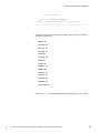
1.0. Contents . . . . . . . . . . . . . . . . . . . . . . . . . . . . . . . . . . . . . . iii
2.0. Introduction . . . . . . . . . . . . . . . . . . . . . . . . . . . . . . . . . . . 1
3.0. Documentation . . . . . . . . . . . . . . . . . . . . . . . . . . . . . . . 2
4.0.
5.0.
6.0.
7.0.
4.3
8.0.
3.1. PowerMAX OS Software Documentation . . . . . . . . 2
3.2. Vendor Documentation . . . . . . . . . . . . . . . . . . . . . . 3
Prerequisites . . . . . . . . . . . . . . . . . . . . . . . . . . . . . . . . . . 4
4.1. Software . . . . . . . . . . . . . . . . . . . . . . . . . . . . . . . . . . . 4
4.2. Hardware . . . . . . . . . . . . . . . . . . . . . . . . . . . . . . . . . . 4
4.2.1. CPU . . . . . . . . . . . . . . . . . . . . . . . . . . . . . . . . . . . 4
4.2.2. System Console Terminal . . . . . . . . . . . . . . . . . . . . 4
4.2.3. SCSI Interface Controller . . . . . . . . . . . . . . . . . . . . 5
4.2.4. Disk/Tape Drives . . . . . . . . . . . . . . . . . . . . . . . . . . 5
4.2.5. Ethernet Controllers . . . . . . . . . . . . . . . . . . . . . . . . 5
4.2.6. FDDI Controllers . . . . . . . . . . . . . . . . . . . . . . . . . . . 6
4.2.7. HPS . . . . . . . . . . . . . . . . . . . . . . . . . . . . . . . . . . . . 6
4.2.8. HSDE . . . . . . . . . . . . . . . . . . . . . . . . . . . . . . . . . . . 6
4.2.9. 1553 V2 . . . . . . . . . . . . . . . . . . . . . . . . . . . . . . . . . 6
4.2.10. 1553 V5 . . . . . . . . . . . . . . . . . . . . . . . . . . . . . . . . 6
4.2.11. DR11-W . . . . . . . . . . . . . . . . . . . . . . . . . . . . . . . . 6
4.2.12. IEEE488 . . . . . . . . . . . . . . . . . . . . . . . . . . . . . . . . 6
4.2.13. Multiplexer VMEbus Controller (MVC) . . . . . . . . . . 6
4.2.14. Parallel Printer Port . . . . . . . . . . . . . . . . . . . . . . . . 7
4.2.15. Fibre Channel . . . . . . . . . . . . . . . . . . . . . . . . . . . 7
4.2.16. Real-Time Clocks and Interrupts (RCIM) . . . . . . . . . 7
System Installation . . . . . . . . . . . . . . . . . . . . . . . . . . . . . 8
5.1. Software Packages . . . . . . . . . . . . . . . . . . . . . . . . . . 8
5.2. Package Descriptions . . . . . . . . . . . . . . . . . . . . . . . 14
5.3. Large SCSI Disk Support . . . . . . . . . . . . . . . . . . . . . . 23
5.4. System Disk Configuration . . . . . . . . . . . . . . . . . . . . 23
5.5. Installation Modes . . . . . . . . . . . . . . . . . . . . . . . . . . 25
5.5.1. Custom Mode of Installation . . . . . . . . . . . . . . . . 25
5.5.2. Semi-Automatic Mode of Installation . . . . . . . . . . 25
5.6. Installation Procedure . . . . . . . . . . . . . . . . . . . . . . . 28
5.7. Standalone Commands . . . . . . . . . . . . . . . . . . . . . 30
5.8. Installing Additional Packages . . . . . . . . . . . . . . . . 30
Rebooting The System . . . . . . . . . . . . . . . . . . . . . . . . 32
General Notes . . . . . . . . . . . . . . . . . . . . . . . . . . . . . . . 33
7.1. XFS . . . . . . . . . . . . . . . . . . . . . . . . . . . . . . . . . . . . . . . 33
7.2. PCI-to-PCI Bridge Configuration . . . . . . . . . . . . . . . 33
Changes From Previous Release . . . . . . . . . . . . . . . 34
8.1. Operating System . . . . . . . . . . . . . . . . . . . . . . . . . . . 34
8.1.1. Architecture Unification . . . . . . . . . . . . . . . . . . . . 34
8.2. Uniprocessor/Multiprocessor Unification . . . . . . . . 35
8.3. NVRAM Global Environment Variable Support . . 35
8.4. Diskless Systems . . . . . . . . . . . . . . . . . . . . . . . . . . . . . 35
8.4.1. Packaging and Configuration . . . . . . . . . . . . . . . 35
8.4.2. Flashboot . . . . . . . . . . . . . . . . . . . . . . . . . . . . . . 36
8.4.3. Closely-Coupled FBS . . . . . . . . . . . . . . . . . . . . . . 36
8.4.4. Remote Message Queues and Semaphores . . . . . 37
8.5. Fibre Channel . . . . . . . . . . . . . . . . . . . . . . . . . . . . . . 37
Motorola Single Board Computer (SBC) PowerMAX OS Version 4.3 Release Notes
iii
Contents
8.6. Real-Time Clocks and Interrupts Module . . . . . . . .
8.7. Per-STREAM CPU Biasing of Service Procedures . .
8.8. iobus_err(2) Support . . . . . . . . . . . . . . . . . . . . . . . . .
8.9. User Level PCI . . . . . . . . . . . . . . . . . . . . . . . . . . . . . .
8.10. Other Enhancements . . . . . . . . . . . . . . . . . . . . . .
8.10.1. httpd Daemon . . . . . . . . . . . . . . . . . . . . . . . . .
8.10.2. DMA Driver for Power Hawk Model 620/640 . . . .
8.10.3. Lockd . . . . . . . . . . . . . . . . . . . . . . . . . . . . . . . .
8.10.4. MVC Real-Time Mode . . . . . . . . . . . . . . . . . . . .
8.10.5. Sparse-Copy Capability . . . . . . . . . . . . . . . . . . .
8.10.6. Normalization in a Leap Year . . . . . . . . . . . . . . .
8.10.7. make Utility Enhancement . . . . . . . . . . . . . . . . . .
8.10.8. UNIX Sockets Limit Increase . . . . . . . . . . . . . . . .
8.10.9. Console on COM2 Port Restriction . . . . . . . . . . .
8.10.10. Power Hawk/PowerStack II lpt Port Hang . . . . . .
8.10.11. VHSD Kernel-Level Driver . . . . . . . . . . . . . . . . . .
8.10.12. Distributed XFS File Systems . . . . . . . . . . . . . . . .
8.11. Compilation Systems . . . . . . . . . . . . . . . . . . . . . . .
8.11.1. Assembler (as) . . . . . . . . . . . . . . . . . . . . . . . . . .
8.11.2. Debugger (adb) . . . . . . . . . . . . . . . . . . . . . . . . .
8.11.3. Disassembler (dis) . . . . . . . . . . . . . . . . . . . . . .
8.11.4. C++ Headers for C Library . . . . . . . . . . . . . . . . .
9.0. Compatibility Issues Between Systems . . . . . . . . . .
10.0. Manual Pages . . . . . . . . . . . . . . . . . . . . . . . . . . . . . .
11.0. Direct Software Support . . . . . . . . . . . . . . . . . . . . . .
38
38
39
39
40
40
40
40
40
40
41
41
41
41
41
41
41
42
42
42
42
42
46
48
49
Manual Pages:
format– format program for Generic Disk driver disks on
page -51
pkgadd – transfer software package or set to the system on
page -53
iv
Motorola Single Board Computer (SBC) PowerMAX OS Version 4.3 Release Notes
4.3
putdev – create and update the device database on
page -57
Introduction
1.0.
Introduction
This document provides a general overview of PowerMAX OSTM 4.3. Release 4.3 is designed to provide
support for the following Motorola Single Board Computers (SBCs):
-
Power HawkTM Model 620 and 640
PowerStack IITM (MTX) 1
PowerStack IITM (MTX PCI Series (7 - slot)) 1
Motorola MCP750
PowerMAX OS is based on UNIX System V Release 4.2 MP with real-time enhancements provided
by Concurrent Computer Corporation.
The PowerMAX OS release is distributed on multiple tapes. The Base Installation tape contains
standalone utilities, a bootable mini-kernel, system installation software, file system restore utility, and
the base software package. The Additional Packages tape contains optional software packages that may
be installed once the base package is installed.
4.3
1
Unless otherwise stated, information presented in these notes is applicable to both
PowerStack II systems, i.e., MTX and MTX PCI Series (7 - slot).
Motorola Single Board Computer (SBC) PowerMAX OS Version 4.3 Release Notes
1
Documentation
2.0.
Documentation
2.1.
PowerMAX OS Software Documentation
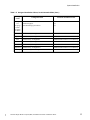
Table 1-1 lists the PowerMAX OS documentation available from Concurrent. Note that
standalone release notes are available for the various platforms. The corresponding release
notes will be provided with the applicable platform.
Table 1-1. PowerMAX OS Software Documentation
Manual Name
Pub. Number
PowerMAX OS Programming Guide
0890423-060
Character User Interface Programming
0890424-000
Device Driver Programming
0890425-060
STREAMS Modules and Drivers
0890426-020
User’s Guide
0890428-010
System Administration Volume 1
0890429-050
System Administration Volume 2
0890430-060
Motorola Single Board Computer PowerMAX OS Version 4.3 Release Notes
0891058-4.3
Compilation Systems Volume 1 (Tools)
0890459-050
Compilation Systems Volume 2 (Concepts)
0890460-050
PowerMAX OS Real-Time Guide
0890466-060
PowerMAX OS Documentation Overview
0890470-070
PowerMAX OS Guide to Real-Time Services
0890479-060
Diskless Systems Administrator’s Guide
0891080-000
Closely-Coupled Programming Guide
0891081-000
Motorola Single Board Computer Console Reference Manual
0830050-030
Copies of the Concurrent documentation can be ordered by contacting the Concurrent
Software Support Center. The toll-free number for calls within the continental United
States is 1-800-245-6453. For calls outside the continental United States, the number is
1-954-971-6248.
2
Motorola Single Board Computer (SBC) PowerMAX OS Version 4.3 Release Notes
4.3
Standalone product release notes are sometimes provided with software products. The
release notes you receive will be at the software revision level that matches the associated
software product level.
Documentation
2.2.
Vendor Documentation
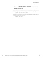
Motorola commercial off-the-shelf (COTS) documentation applicable to the various
Motorola Single Board Computers (SBC), are listed below. You may contact your local
Motorola sales office to purchase Motorola manuals not provided with the system or you
may access the Motorola on-line documentation site at: “www.mcg.mot.com/literature”.
See the table below for a list of Motorola manual names and document numbers.
Motorola
Pubs No.
Manual Name
4600
Series
(2)
MTX
Series
(3)
MTX
PCI
Series
(4)
MCP
750
(5)
MVME2600 Series Single Board
Computer Installation and Use
V2600A/IH
X
-
-
-
MVME4600 Series VME Processor
Module Installation and Use
V4600A/IH
-
X
-
-
MTX Series MotherBoard
Installation and Use
MTXA/IH1
-
-
X
MTX PCI Series MotherBoard
Installation and Use
MTXPCIA/IH
-
-
-
X
-
PPCBug Firmware Package User’s
Manual - Parts 1 and 2
PPCBUGA1/UM &
PPCBUGA2/UM
-
X
X
X
X
MTX Series MotherBoard
Programmer’s Reference Guide
MTXA/PG
-
-
X
-
-
MTX PCI Series MotherBoard
Programmer’s Reference Guide
MTXA/PG
-
-
X
-
-
MVME712M Transition Module and P2
Adapter Board Installation and Use
Manual
MVME712MA/IH
X
X
-
-
MVME761Transition Module
Installation and Use
VME761A/IH
X
X
-
-
PowerPC Open Firmware User’s Manual Volumes 1 and 2
PPCOFWA1/UM &
PPCOFWA2/UM
X
-
-
-
MCP750 CompactPCI Single Board MCP750A/lH1
Computer Installation and Use
-
-
-
-
X
MCP750 CompactPCI Single Board MCP750A/PG1
Computer Programmer’s Reference Guide
-
-
-
-
X
Legend:
4.3
2600
Series
(1)
(1)
(2)
(3)
(4)
(5)
Power Hawk 620 (PH620)
Power Hawk 640 (PH640)
PowerStack II (MTX)
PowerStack II (MTX PCI Series (7 - slot))
Motorola MCP750
Motorola Single Board Computer (SBC) PowerMAX OS Version 4.3 Release Notes
3
Prerequisites
3.0.
Prerequisites
3.1.
Software
PowerMAX OS operating system release 4.3 or later.
3.2.
Hardware
3.2.1.
CPU
Single board computer (SBC) with minimum of 32MB of memory Power Hawk 620 (Motorola MVME2604 (PowerPC 604eTM))
Power Hawk 640 (Motorola MVME4604 (Dual PowerPC 604eTM))
PowerStack II (Motorola MTX)
PowerStack II (Motorola MTX PCI Series (7 - slot))
Motorola MCP750
NOTE
The PowerStack II and Motorola MCP750 systems do not have a VME backplane.
Therefore, any references in these release notes to VME, VME devices, software
applicable to VME, etc., do not apply to the PowerStack II or Motorola
MCP750 systems.
3.2.2.
System Console Terminal
The system console may be either:
•
a video display terminal such as a Wyse 150, vt100, or comparable device
connected to serial port 0 (COM1).
•
a PC style keyboard/VGA/display combination, if equipped.
Supported VGA compatible devices may include the following:
•
Built-in SVGA port of Power Hawk Model 640
•
ACT/Technico PMC-8030 SVGA PMC card
•
Matrox Millennium/Millennium II PCI cards
4
Motorola Single Board Computer (SBC) PowerMAX OS Version 4.3 Release Notes
4.3
If equipped with a keyboard and one of these VGA compatible devices, the default
console interface will be the keyboard and display. The default system console
device can be modified via the console tc command.
Prerequisites
3.2.3.
SCSI Interface Controller
Note
The NCR 53C825 SCSI (ncr) controller is available on a PMC card on the
Motorola MCP750.
Minimum requirements are:
3.2.4.
•
Internal NCR 53C825 SCSI (ncr) controller. This is built into the Power
Hawk or PowerStack II CPU board OR VME Interface Adapter (VIA), PN
1580009. Minimum Rev is -1.
•
At least one supported SCSI disk drive for system files and swap space.
•
At least one supported SCSI tape device for software installation and updates.
Disk/Tape Drives
As stated above, each system must have a system disk and tape drive. The smallest
disk drive supported for the installation disk (that contains the PowerMAX OS
executable) is 2GB.
The installation disk is supported by a VIA, IDE1 or NCR SCSI controller (the
NCR SCSI is recommended). A disk or tape containing the console processor
boot software must be attached to the NCR SCSI.
3.2.5.
Ethernet Controllers
3.2.5.1.
DEC Ethernet Controller
Ethernet may be provided with the on-board DEC 21040, 21140 or
21143 Ethernet chip.
3.2.5.2.
PCI/PMC DEC Ethernet Controller
Additional networking connections are possible with selected PCI or
PMC-based DEC 21040, 21140A, 21142 and 21143 controller chips.
Contact your Concurrent representative to determine if a particular
card is supported.
3.2.5.3.
Interphase 4207 Eagle
VME-based Ethernet may be provided via the Interphase 4207 Eagle
Ethernet Controller which supplies AUI connections. The minimum
revision level of the ethernet controller board (PN 2010221) is Rev E.
3.2.5.4.
Interphase 4221 Condor
VME-based Ethernet may be provided via the Interphase 4221
Condor Ethernet Controller which supplies AUI connections. The
minimum revision level of the ethernet controller board (PN 2010316)
is Rev A.
4.3
1. IDE supported on PowerStack II only.
Motorola Single Board Computer (SBC) PowerMAX OS Version 4.3 Release Notes
5
Prerequisites
3.2.6.
FDDI Controllers
3.2.6.5.
Interphase Peregrine 4211
VME-based FDDI is provided via the Interphase 4211 (Peregrine 1)
controller. The minimum revision level of the FDDI controller board
(PN 2010225) is Rev C.
3.2.6.6.
Interphase Peregrine 5211
VME-based FDDI is provided via the Interphase 5211 (Peregrine 2)
controller. The minimum revision level of the FDDI controller board
(PN 2010307) is Rev -.
3.2.7.
HPS
VME-based asynchronous serial communications is provided by the High
Performance Serial (HPS) interface controller. The minimum revision level of the
HPS controller board (PN 2010218) is Rev D.
3.2.8.
HSDE
VME-based HSD interface is provided by the High Speed Driver Enhanced
(HSDE) controller. The minimum revision level of the HSDE controller board
(PN 1573300) is Rev P.
3.2.9.
1553 V2
VME-based MIL-STD-1553 Version 2 (V2) interface is provided by the 1553
controller. The minimum revision level of the 1553 controller board (PN
2010209) is Rev C.
3.2.10.
1553 V5
VME-based MIL-STD-1553 Version 5 (V5) interface is provided by the 1553
controller. ABI-V5-1 is a Single Channel board, and ABI-V5-2 is a Dual Channel
board.
3.2.11.
DR11-W
VME-based controller with a DEC DR11-W protocol external channel interface.
Up to 8 DR11-W boards are supported. The minimum revision level of the DR11W controller board (PN 2010179) is Rev -.
3.2.12.
IEEE488
VME-based IEEE GPIB Bus Interface is provided by the IEEE488 controller. The
minimum revision level of the IEEE488 controller board (PN 2010313) is Rev -.
3.2.13.
Multiplexer VMEbus Controller (MVC)
6
Motorola Single Board Computer (SBC) PowerMAX OS Version 4.3 Release Notes
4.3
VME-based asynchronous serial communication is provided by the Multiplexer
VMEbus Controller.
Prerequisites
3.2.14.
Parallel Printer Port
The parallel printer port is compatible with IEEE standard P1284, as well as
simple Centronics compatibility. The parallel port connector, a 25-pin female DB
connector, is located on the transition module for chassis models, or on the rear
connector panel on desktop models.
3.2.15.
Fibre Channel
An Interphase 5526 Fibre Channel PCI adapter is required for Fibre Channel
arbitrated loop configurations containing Fibre Channel disk drives.
3.2.16.
Real-Time Clocks and Interrupts (RCIM)
4.3
The RCIM is a multi-function PCI mezzanine card (PMC) that provides functions
ideally suited for time-critical applications. Up to sixteen CPU boards, in the
same or different chassis, can be linked via the RCIMs synchronization cable. The
RCIM can be installed on any system with an available PMC slot. Refer to the
Real-Time Clock & Interrupt Module User’s Guide for more information.
Motorola Single Board Computer (SBC) PowerMAX OS Version 4.3 Release Notes
7
System Installation
4.0.
System Installation
The PowerMAX OS operating system is installed as software packages using the Software Packaging
Tools. Two installation modes, Custom and Semi-Automatic, are now available. Refer to Installation
Modes on page 25 for additional details.
4.1.
Software Packages
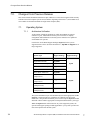
This section contains brief descriptions of available software packages. Note that your
complement of available software may be less than that shown in Table 1-2 and entirely
depends on the optional software packages you purchased.
The availability of a software package for all currently supported platforms is shown in
Table 1-2 by a “y” (yes) or “n” (no) in the appropriate column.
Package dependencies are also specified in Table 1-2. Packages with dependencies must be
installed after the packages they depend on.
When installing the optional package(s) from the system installation menu, you must also
remember to select all required dependency package(s). The installation scripts will install
the packages in the proper order.
Some optional packages are relocatable, that is, objects may be installed in an alternative
directory other than root. When installing a relocatable package, the user will be prompted
for an alternate installation path.
8
Motorola Single Board Computer (SBC) PowerMAX OS Version 4.3 Release Notes
4.3
Note that all packages are dependent on base.
System Installation
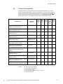
Table 1-2. Software Packages
Package Description
Night
Power
Hawk
Turbo
Power
Power
Stack
HN6200/ Hawk MAXION Hawk
II
HN6800
MCP
750
Package
Name
Package
Dependencies
Standard:
Base System
y
y
y
y
y
y
base
Advanced Commands
y
y
y
y
y
y
cmds
Closed SARs
y
y
y
y
y
y
sar
Cross Compiling Libraries
y
y
y
y
y
y
crosslibs
Domestic Encryption Utilities
y
y
y
y
y
y
crypt
Fortran Libraries
y
y
y
y
y
y
hf77libs
International Encryption Utilities
y
y
y
y
y
y
crypt-int
Kernel Debugger
y
y
y
y
y
y
kdb
Network Support Utilities
y
y
y
y
y
y
nsu
OA&M
y
y
y
y
y
y
oam
Online Manual Pages
y
y
y
y
y
y
man
Printer Support
y
y
y
y
y
y
lp
Program Analyzer
y
y
y
y
y
y
analyze
Software Packaging Tools
y
y
y
y
y
y
softint
Terminfo Utilities
y
y
y
y
y
y
terminf
Condor Ethernet Driver
y
y
y
y
n
n
cnd
CD-ROM Driver
y
y
y
y
y
y
cdfs
DR11W
y
y
y
y
n
n
dr11w
Eagle Ethernet Driver
y
y
y
y
n
n
egl
Interphase 5526 Fibre Channel
Driver
n
n
n
n
y
n
fibre
Generic SCSI Device Driver
y
y
y
y
y
y
gs
lp,nsu
cmds
4.3
Drivers:
Motorola Single Board Computer (SBC) PowerMAX OS Version 4.3 Release Notes
nsu
nsu
9
System Installation
Table 1-2. Software Packages (Cont.)
Package Description
Night
Power
Hawk
Turbo
Power
Power
Stack
HN6200/ Hawk MAXION Hawk
II
HN6800
MCP
750
Package
Name
Package
Dependencies
Drivers (Cont):
y
y
y
y
n
n
hps
HSDE
y
y
y
y
n
n
hsde
Peregrine FDDI Driver
y
y
y
y
n
n
pg
X.25 Driver
y
y
y
y
n
n
ix25
1553 V2 ABI Driver
y
y
y
y
n
n
1553drv
1553 V2 ABI Libraries
y
y
y
y
n
n
1533lib
1553 V5 ABI Driver
y
y
y
y
n
n
1553v5drv
1553 V5 ABI Libraries
y
y
y
y
n
n
1533v5lib
1553v5drv
Integral SCSI/Ethernet (ISE)
- ISE SCSI Driver
- ISE Ethernet Driver
y
y
y
n
n
n
n
n
n
n
n
n
n
n
n
n
n
n
ise
is
ie
ise
ise,nsu
NCR SCSI Driver
n
y
y
y
y
y
ncr
DEC Ethernet Driver
n
y
y
y
y
y
dec
Internal IDE/ATA Disk Controller
n
n
n
n
y
n
ide
Intelligent Bus Interface Module
(IBIM)
y
y
y
y
n
n
ibim
MVME300 IEEE 488
y
y
y
n
n
n
mvme300
VIA SCSI Adapter Driver
y
y
y
y
n
n
via
Parallel Port Driver
n
n
n
y
y
y
lpt
Multiplexer VMEbus Controller
y
y
y
y
n
n
mvc
National Instruments GPIB
User-Level Device Driver (GPIB)
y
y
y
y
n
n
ngpib
VMIC High Speed Data (HSD)
Driver
y
y
y
y
n
n
vhsd
nsu
1553drv
nsu
Motorola Single Board Computer (SBC) PowerMAX OS Version 4.3 Release Notes
4.3
10
High Performance
Serial Driver(HPS)
System Installation
Table 1-2. Software Packages (Cont.)
Package Description
Night
Power
Hawk
Turbo
Power
Power
Stack
HN6200/ Hawk MAXION Hawk
II
HN6800
MCP
750
Package
Name
Package
Dependencies
TCP/IP Networking:
Internet Utilities
y
y
y
y
y
y
inet
nsu
Commands Networking Extension
y
y
y
y
y
y
netcmds
lp,inet
y
y
y
y
y
y
rpc
inet
Network File System Utilities
y
y
y
y
y
y
nfs
nsu, inet,
rpc, dfs
Distributed File System Utilities
y
y
y
y
y
y
dfs
inet
y
y
y
y
y
y
audit
n
n
n
y
y
y
diskless
Frequency-Based Scheduler and
Performance Monitor
y
y
y
y
y
y
fbs
Frequency-Based Scheduler
Manual Pages
y
y
y
y
y
y
fbsman
Concurrent Compilation System
y
y
y
y
y
y
hc
Fortran 77 Compilation System
y
y
y
y
y
y
hf77
C++ Compiler System
y
y
y
y
y
y
c++
TCP/IP Networking (Cont):
Remote Procedure Calls Utilities
Network File System:
Security:
Auditing
Closely-Coupled Systems and
Loosely-Coupled Systems:
Diskless
cmds, nfs,
netcmds, dec,
and ncr or via
Frequency-Based Scheduler:
4.3
Software Development:
Motorola Single Board Computer (SBC) PowerMAX OS Version 4.3 Release Notes
analyze
11
System Installation
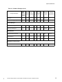
Table 1-2. Software Packages (Cont.)
Package Description
Night
Power
Hawk
Turbo
Power
Power
Stack
HN6200/ Hawk MAXION Hawk
II
HN6800
MCP
750
Package
Name
Package
Dependencies
Ada Programming Support
Environment (HAPSE)
y
y
y
y
y
y
ada
analyze
Ada X Interface (AXI)
y
y
y
y
y
n
axi
ada, x11
Ada Runtime Shared Libraries
y
y
y
y
y
n
ada_rts
MAXAda Compilation System
y
y
y
y
y
n
MAXAda
analyze
y
y
y
y
y
n
MAXaxi
MAXAda, x11
y
y
y
y
y
y
x11ipc
Software Development (Cont):
AXI for MAXAda
Window System:
X Window System with OSF/Motif:
x11
x11ipc
x11progs
x11ipc, x11
x11dev
x11ipc, x11,
x11progs
x11pman
x11dman
Metro-X X11R6 Server
n
n
y
y
y
y
metroess
X11R6 Fonts
n
n
y
y
y
y
xfonts
Metro Link OpenGL
y
y
y
y
y
y
metrogl
NightBench
y
y
y
y
y
y
nbench
x11
NightProbe
y
y
y
y
y
y
nprobe
x11
NightSim
y
y
y
y
y
y
nsim
x11
NightTrace
y
y
y
y
y
y
ntrace
x11
NightTune
y
y
y
y
y
y
ntune
x11
12
Motorola Single Board Computer (SBC) PowerMAX OS Version 4.3 Release Notes
4.3
NightStar Tools:
System Installation
Table 1-2. Software Packages (Cont.)
Package Description
Night
Power
Hawk
Turbo
Power
Power
Stack
HN6200/ Hawk MAXION Hawk
II
HN6800
MCP
750
Package
Name
Package
Dependencies
NightView
y
y
y
y
y
y
NightView x11
NightView Debugger Support
y
y
y
y
y
y
Nviewp
Élan License Manager5
y
y
y
y
y
y
elan5lm
Élan License Manager4
y
y
y
y
y
y
elan4lm
elan5lm
Distributed XFS File System
y
y
y
y
y
y
xfsd
inet, rpc
Virtual Partition
y
y
y
y
y
y
vp
VERITAS Volume Manager
y
y
y
n
n
n
vxvm
n
n
n
n
y
n
cld
License Manager:
Miscellaneous:
nsu
MediaHawk (VOD) Specific:
4.3
4/8 Port MPEG Decoder Driver
Motorola Single Board Computer (SBC) PowerMAX OS Version 4.3 Release Notes
13
System Installation
4.2.
Package Descriptions
The following pages contain a brief description of all of the packages available on
PowerMAX OS. Refer to Table 1-2 to determine if the package listed is applicable to your
system.
Description of Standard Packages:
Base System (base)
The Base System package provides the base set of commands and system
utilities.
Printer Support (lp)
Although some printing capabilities are provided in the base package, more
advanced printing capabilities, and a wider range of printers, are included in the
Printer Support package.
Network Support Utilities(nsu)
The Network Support Utilities package provides the basis on which networking
capabilities are built.
Terminfo Utilities (terminf)
The Terminfo Utilities Package provides support for a wide variety of terminals
beyond those provided in the base package.
Advanced Commands (cmds)
The Advanced Commands package provides the remaining user and
administrative commands.
Program Analyzer (analyze)
This package provides utilities for performance analysis and post-linker
optimization.
Cross Compiling Libraries (crosslibs)
Libraries for cross-compilation between architecture types, i.e., between the Night
Hawk architecture (HN6200/HN6800/TurboHawk/PowerMAXION) and the
Motorola architecture (Power Hawk/PowerStack II/MCP750). Libraries can be
found in /usr/lib/crosslibs. Each architecture type contains the other's
libraries.
hf77libs (hf77libs)
This package provides runtime libraries for the Fortran 77 Compilation System.
OA&M (oam)
The Operations Administration and Maintenance package provides a characterbased, menu-oriented interface to a wide variety of advanced, server-oriented
administrative tasks.
Software Packaging Tools (softint)
14
Motorola Single Board Computer (SBC) PowerMAX OS Version 4.3 Release Notes
4.3
This package provides tools to support the development process and includes a
variety of archive libraries as well as tools to create and modify packages.
System Installation
Kernel Debugger (kdb)
The Kernel Debugger package provides a tool to assist in the porting and
debugging of kernel modules and drivers by allowing the developer to examine
and control a running kernel.
Domestic Encryption Utilities (crypt)
The Domestic Encryption Utilities package supports the encryption of files and
other data. This package is for distribution in the United States.
International Encryption Utilities (crypt-int)
Same as above but for international distribution.
Online Manual Pages (man)
System manual pages (man pages) provided in an on-line format for viewing
using the man command.
Closed SARs (sar)
Software Action Reports (SARs) closed in this release can be found in file
/usr/src/PRODUCTS/SARS.CLOSED.
Description of Drivers Packages:
Condor Ethernet Driver (cnd)
This package supports the Condor Ethernet 4211 VME board. Up to 6 Condor
Ethernet boards are supported.
CD-ROM Driver (cdfs)
The CD-ROM package provides read-only access to file systems on SCSI CDROM devices. ISO-9660 and High Sierra formats are supported.
Eagle Ethernet Driver (egl)
This package supports the Interphase Ethernet 4207 Eagle VME board. Up to 6
Eagle Ethernet boards are supported.
Fibre Channel Driver (fibre)
This driver package supports the Interphase 5526 Fibre Channel Driver in an
arbitrated loop configuration. This package also provides for automatic
configuration of the controller during system initialization (e.g., no
Sadapters(4) file changes required). Up to 126 nodes, where a node may be
a Fibre channel disk or a Fibre Channel adapter card attached to a computer host,
may be attached to the arbitrated loop. This package also contains the
fibconfig(1M) utility, which may be used to provide additional Fibre channel
configuration control and status information.
Parallel Port Driver (lpt)
This driver package supports the parallel port on the Power Hawk. Only one
parallel port is supported per system. This driver supports local printing to a
directly connected printer.
Peregrine FDDI Driver (pg)
4.3
This package supports the Interphase FDDI 4211 and 5211 Peregrine VME
boards. Up to 3 Peregrine VME boards are supported.
Motorola Single Board Computer (SBC) PowerMAX OS Version 4.3 Release Notes
15
System Installation
Generic SCSI Device Driver (gs)
The gs driver package supports the following SCSI devices: SCSI-based CPUs,
scanners, printers, media changers, and communication devices. The gs driver
communicates with the HSA and VIA controllers/drivers using the drivers
passthru options to send SCSI commands to the appropriate SCSI devices.
High Performance Serial Driver (hps)
This package supports the High Performance Serial adapter, a VME board
providing 16 asynchronous serial ports running up to 38400 baud, and 1 optional
Centronics parallel printer port. Up to eight HPS adapters are supported.
VIA SCSI Adapter Driver (via)
This driver package supports the following:
a. SCSI Adapter Interface (hsa), an HVME board providing mass storage
capability to the system. Up to 7 Concurrent specified SCSI disks or tapes
may be connected to a single HSA board. HSA boards are available only on
HN6200, HN6800 and TurboHawk systems.
b. VME Interface Adapter for SCSI (via), a VME board providing mass
storage capability to the system. Up to 30 (if using 16-bit wide SCSI)
Concurrent specified SCSI disks or tapes may be connected to a single VIA
board. The VIA board supports up to two optional daughter cards. Each
daughter card can be one of the following:
1. SCSI-2 card that supports fast and wide single ended SCSI-2 transfers.
2. SCSI-2 differential card that supports fast and wide transfers.
Refer to online manual page dlvia(8) for information on how to download
VIA-board firmware.
Intelligent Bus Interface Module (ibim)
This driver package supports the IBIM module. The IBIM module is a data
acquisition module that acts as a host platform for a variety of analog and digital
interface modules. The IBIM can support up to four daughter boards.
NCR 53C8xx SCSI Driver (ncr)
This driver package supports the internal SCSI controller chip and the controller
chips on separate PMC or PCI cards. Supported controllers include the 53C810,
53C825, 53C825A and 53C875. This package also provides for automatic
configuration of the controller during system initialization (e.g., no
Sadapters(4) file changes required). Up to seven disks and/or tape drives
may be connected to this SCSI bus.
Internal IDE/ATA Driver (ide)
16
Motorola Single Board Computer (SBC) PowerMAX OS Version 4.3 Release Notes
4.3
This driver package supports up to four ATA-2 or ATA-3 disk drives attached to
the internal IDE/ATA disk controller on PowerStack II systems only. This
package also provides for automatic configuration of the controller during system
initialization (e.g., no Sadapters(4) file changes required). (The ability to
format an IDE drive is not available. IDE drives are formatted at the factory and
cannot be reformatted in the field. In addition, there is no verify function.)
System Installation
DEC 21x4x Ethernet Driver (dec)
This driver package supports the Ethernet controller chip on the TurboHawk,
PowerMAXION, Power Hawk, PowerStack II and Motorola MCP750 processor
cards along with DEC 21x4x controller chips on separate PMC or PCI cards.
Supported chips include the 21040, 21140A, 21142 and 21143. This package also
provides for automatic configuration of the controller during system initialization
(e.g., no Sadapters(4) file changes required).
100baseT (except on the 21040), 10baseT, BNC and AUI connections are
supported. The Power Hawk Model 620/640 processor contains a 21140A with
10baseT or 100baseT connections. The TurboHawk has an embedded DEC 21143
with 10baseT or 100baseT connections.
High Speed Data Enhanced Channel Driver (hsde)
This package supports the HSDE Channel Interface. The HSDE provides highspeed, 32-bit parallel bidirectional link for transferring control, status and data
between the HN6200/HN6800/TurboHawk (H)VMEbus system and an external
device using the Encore HSD Interface Model 9132 protocol.
1553 V2 ABI Driver (1553drv)
This package provides a user-level device driver for the Version 2 (V2) Advanced
Bus Interface (ABI) MIL-STD-1553 Adapter.
1553 V2 ABI Libraries (1553lib)
This package provides program interfaces that can be used within an application
program. This interface is the same as those provided by the manufacturer of the
1553 board, SBS Engineering, Inc.
1553 V5 ABI Driver (1553v5drv)
This package provides a user-level device driver for the Version 5 (V5) Advanced
Bus Interface (ABI) MIL-STD-1553 Adapter board manufactured by SBS
Engineering, Inc.
1553 V5 ABI Libraries (1553v5lib)
This package provides program interfaces which can be used within an application
program to control the ABI-VI MIL-STD-1553 Adapter. This set of interfaces is
an enhanced version of the set provided by the manufacturer of the board, SBS
Engineering, Inc.
Motorola MVME300 IEEE488 Interface Driver (mvme300)
This package supports the Motorola's MVME300 IEEE 488 bus interface
controller. Up to 8 MVME300 controllers are supported.
Ikon DR11W Driver (dr11w)
This package supports the Ikon 10089 DR11W emulator board. Up to 16 DR11W
boards are supported (8 in the Primary I/O bus, 8 in the Secondary I/O bus).
Integral SCSI/Ethernet Controller (ise)
4.3
Provides base support for the Integral SCSI/Ethernet daughtercards (ISE)
available with HN6200/6800 systems only. Package supports up to 4 ISE cards
(one per processor board), and provides for automatic configuration of ISE cards
during system initialization (e.g., no Sadapters(4) file changes required).
Motorola Single Board Computer (SBC) PowerMAX OS Version 4.3 Release Notes
17
System Installation
ISE - SCSI (is)
Provides driver support for up to seven SCSI peripherals for each
configured ISE daughtercard.
ISE - Ethernet (ie)
Provides Ethernet/IEEE 802.3 local area network driver support for
each configured ISE daughtercard.
X.25 Driver (ix25)
This package supports the X.25 high speed synchronous communication module
that runs X.25/LAPB/HDLC.
Multiplexer VMEbus Controller (mvc)
This package supports the Multiplexer VMEbus Controller (MVC) adapter board.
The MVC adapter board provides 16 asynchronous serial ports running at up to
38.4 baud, and one optional Centronic parallel printer port. Up to four MVC
adapter boards are supported.
National Instruments GPIB User-Level Device Driver (ngpib)
The ngpib user-level device driver provides programmers with a configuration
utility and library functions to access and control a National Instruments General
Purpose Interface Bus (GPIB) 1014D board. This interface is a dual ported, high
performance interface to the IEEE-488 bus, and is capable of controlling two
independent GPIB bus configurations.
vhsd Driver (vhsd)
This driver provides support for the VMIC VMIVME-5620 Intelligent HSD
Emulator on Power Hawk 620/640 platforms.
Description of TCP/IP Networking Packages:
Internet Utilities (inet)
The inet package includes the software needed to run the TCP/IP network and
tools such as ftp, telnet, and rcp.Administrative software for setting up the
network is also included.
Commands Networking Extension (netcmds)
The Commands Networking Extension Package extends the functionality of
several basic commands by supporting the means to share printers across a
network, and use additional transport mechanisms for the sending and receiving
of electronic mail.
Remote Procedure Calls Utilities (rpc)
The Remote Procedure Calls Utilities package supports the remote execution
facility.
Description of Network File System Packages:
Network File System Utilities (nfs)
18
Motorola Single Board Computer (SBC) PowerMAX OS Version 4.3 Release Notes
4.3
The Network File System Utilities package supports the means to transparently
share resources across a network with other computers running the Network File
System.
System Installation
Distributed File System Utilities (dfs)
The dfs utilities package provides a simple user interface for performing
networked operations such as advertising local resources and accessing remote
resources.
Description of Security Package:
Auditing (audit)
The Auditing package provides auditing facilities allowing a system administrator
or security auditor to record and report all security-related events that occur on the
system.
Description of Closely-Coupled Systems and
Loosely-Coupled Systems:
Diskless (diskless)
This package provides support to configure and control multiple Motorola singleboard computers (SBC) in a common VME chassis using the VMEbus as a pointto-point network interface. Additionally, this package can support multiple SBC
in one, or more, remote VME chassis connected via Ethernet. Diskless SBC's can
be booted via the VMEbus, or can boot itself via NET BOOT (boot via TFTP over
Ethernet).
Description of Frequency-Based Scheduler Packages:
Frequency-Based Scheduler and Performance Monitor (fbs)
This package provides kernel support for the Frequency-Based Scheduler and
Performance Monitor and Real-Time Command Processor.
Frequency Based Scheduler Manual Pages (fbsman)
This package provides the man pages associated with the Frequency-Based
Scheduler and Performance Monitor.
Description of Software Development Package:
Concurrent C Compilation System (hc)
This package provides the hc C compiler. This compiler offers ANSI C
compliance and support for pre-ANSI C, together with other extensions.
Fortran 77 Compilation System (hf77)
This package provides the hf77 Fortran compiler and runtime libraries. This
compilation system offers Fortran 77 and MIL-STD 1753 compliance, together
with many popular extensions and a cross-reference tool with interface checking.
C++ Compiler System (c++)
This package provides the Concurrent C++ compiler that closely tracks the ANSI
C++ Standard.
Ada Programming Support Environment (ada)
4.3
This package consists of a validated Ada compiler, library, management tools,
symbolic debugger, automated build utility, Ada bindings, real-time monitoring,
the Ada Real-Time Multiprocessor tasking executive (ARMS) and runtime support
libraries.
Motorola Single Board Computer (SBC) PowerMAX OS Version 4.3 Release Notes
19
System Installation
Ada to X Interface (AXI) (axi)
This package consists of the Ada to X Window system interface.
Ada Runtime Shared-Libraries (ada_rts)
This package consists of the compiled and linked form of HAPSE Runtime
Shared-Libraries; including the basic Ada Real-Time Multiprocessor System
(ARMS) standard libraries, Ada bindings, and others.
MAXAda Compilation System (MAXAda)
This package consists of the MAXAdaTM tool set for the development of Ada
programs on Concurrent computers under the PowerMAX OS environments.
MAXAda processes the Ada language as specified by the Reference Manual for
the Ada Programming Language, ANSI/ISO/IEC-8652:1995.
Ada to X Interface for MAXAda (MAXaxi)
This package consists of the Ada X Window system interface for MAXAda.
Description of X Window System Packages:
X Window System Version 11, Release 6 (x11)
Includes OSF/Motif commands, libraries and header files. X Window System
sub-package names and short descriptions follow:
x11ipc
x11
x11progs
x11dev
x11pman
x11dman
the libraries for ICE and ktalk only
all other libraries including runtime support files they reference
the X client programs xdm, mwm, app-default files, etc.
the X program development tools, header files, imake, static libs,
etc.
man pages for all the application level programs.
man pages for the libraries and program development tools
Metro-X Enhanced X11R6 server set and OpenGL (metroess, xfonts & metrogl)
Jointly developed with Metro Link, Inc., these packages provide native graphics
capabilities on systems equipped with appropriate display and input devices.
20
metroess
Metro Links Enhanced X11R6 Server Set includes a powerful,
configurable, host based X11R6 server derived from the
X11R6/XFree86 sample servers.
xfonts
Local X11 system fonts, which are required for server installations
that do not use a font server.
metrogl
OpenGL version 1.2 for Metro-X. Includes OpenGL client libraries
(libGL, libGLX, libGLU), header files, sample clients, and GLX
server extension for rendering OpenGL commands with the
Metro-X X11R6 server.
Motorola Single Board Computer (SBC) PowerMAX OS Version 4.3 Release Notes
4.3
Specific packages include:
System Installation
Description of NightStar Tools Packages:
NightBench (nbench)
NightBench is a graphical user interface to MAXAda, a tool set for the
development of Ada programs running under the OS.
NightProbe (nprobe)
This package provides a utility for monitoring and recording data values in one or
more target programs.
NightSim (nsim)
This package provides a utility to control and monitor the Frequency-Based
Scheduler and its Performance Monitor.
NightTrace (ntrace)
This package provides a utility with a graphical interface to trace events occurring
in the kernel and optionally within a user's application.
NightTune (ntune)
This package provides a utility with a graphical interface to monitor and tune a
system.
NightView (NightView)
This package provides a general-purpose, source-level debugger for C, C++,
Fortran and Ada with support for multiple processes.
NightView (Nviewp)
Low level support required for debugger on local or remote machine.
Description of License Manager Packages:
Élan License Manager (elan5lm)
This package contains the license manager daemon and reporting commands
required by license-managed applications, including all NightStar tools. This
version is Y2K compliant.
Élan License Manager (elan4lm)
4.3
This package is an optional ‘old’ (version 4) license manager daemon that can run
in parallel with the new (elan5lm) license manager daemon on the same server
machine in order to support serving licenses to both ‘old’ and ‘new’ tools at the
same time.
Motorola Single Board Computer (SBC) PowerMAX OS Version 4.3 Release Notes
21
System Installation
Description of Miscellaneous Packages:
Distributed XFS File Systems (xfsd)
The xfsd distributed file system package provides shared access to a single file
system from multiple host systems on a multi-initiator disk bus. Unlimited read
access to files in the shared file system is supported. Only limited write access to
files in the shared file system is supported. A network connection between
systems that access a shared file system is required for communication and
synchronization of file system structures.
Virtual Partition (vp)
This package provides a pseudo device driver that performs disk striping (RAID
level 0) or mirrored partitioning (RAID level 1).
VERITAS Volume Manager (vxvm)
This package provides the system administrator with a disk management tool. See
System Disk Configuration on page 23 on how the disk must be configured when
using the VERITAS Volume Manager.
MediaHawk (VOD) Specific Packages:
4/8 Port MPEG Decoder Driver (cld)
22
Motorola Single Board Computer (SBC) PowerMAX OS Version 4.3 Release Notes
4.3
This package supports the Concurrent 4/8 Port PCI MPEG Decoder Card. Each
card supplies 4 or 8 ports of MPEG 1 or MPEG 2 video streams at rates up to 10
mbits per second. The cld driver supports up to 3 cards per PowerStack II
system.
System Installation
4.3.
Large SCSI Disk Support
Changes were introduced in a previous PowerMAX OS release to correct the support for
SCSI disks larger than 8 Gigabytes. These corrections changed the location of the
Geometry Block on these large disks. As a result, disks larger than 8 GB formatted using
the format(1m) or format(8) standalone utility prior to release 4.2 cannot be used to
install release 4.3 without being reformatted.
If you have a disk larger than 8 GB that was formatted using the release 4.1 version of
format(), you must do the following:
1. Backup any data needed on any of the partitions before installation.
2. During the installation, exercise the option to format the disk and rewrite
the partition information (Geometry Block).
3. Finish the Release 4.3 installation.
4. Restore any data backed up in step 1 above.
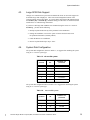
4.4.
System Disk Configuration
The system disk configuration, shown in Table 1-3, is suggested for installing the system
using an ufs root file system type.
Table 1-3. ufs root file system
partition
file
minimum size
(formatted
0
root
100 MB
1
swap
96 MB
2
usr
500 MB
3
var
400 MB
4
----
<remainder>
61
boot
1024 KB
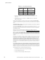
The system disk configuration shown in Table 1-4 is suggested for installing the system
using an xfs root file system type.
4.3
Table 1-4.
xfs root file system
partition
file
minimum size
(formatted
0
/stand
60 MB
1
swap
96 MB
2
usr
500 MB
3
var
400 MB
Motorola Single Board Computer (SBC) PowerMAX OS Version 4.3 Release Notes
23
System Installation
Table 1-4.
xfs root file system (Cont.)
partition
file
minimum size
(formatted
4
----
<remainder>
52
root
60 MB
61
boot
1024 KB
1. Partition is applicable to Power Hawk, PowerStack II and MCP750 boot
disks only.
2. The xfs root must be on partition 5. (Caution: cannot use VxVM with
xfs root file system.)
During system installation, you will be given the option of running the format(1M)
command. You should choose this option to format the system disk and to select partition
sizes.
The format(1M) command “partition default” automatically selects the above partition
sizes for a ufs root file system.
Note that the format(1M) “partition default” option should not be used if an xfs root
file system is selected as the default partitions automatically selected are not appropriate
for the xfs file system.
Partition sizes may be increased and new partitions may be added, but the above
assignments of file systems to partitions and minimum partition sizes must be maintained.
The root and usr file systems should only contain system files and are not expected to
grow much after system installation. The var file system contains system crashfiles, log(s)
and temporary files. It is strongly recommended that user files be restricted from these file
systems.
Swap space needs should be carefully calculated. Adding too little swap space will result
in unnecessary out-of-memory conditions for your applications. Adding too much swap
space will result in too much of your system’s memory being locked down for swap space
management. The total amount of swap space should be at least 1.5 times the size of
physical memory. An initial swap partition is provided on the system disk. If this partition
is insufficient, it is recommended that additional swap partitions be added, preferably on
other disks.
Every Gigabyte of swap space results in 4 Megabytes of physical memory being used for
swap space management. This rule demonstrates that it would be impractical to create a 9
Gigabyte swap device on a 64 Megabyte system, as this would result in more than half (36
Megabytes) of physical memory being utilized by the kernel for swap space management.
Note that partition four is left unused. This partition may be:
1. Redistributed to make the other system partitions bigger.
2. Used for additional swap space.
24
Motorola Single Board Computer (SBC) PowerMAX OS Version 4.3 Release Notes
4.3
3. Used for user files (for example a home file system).
System Installation
Use the format(1M) “?” command for help with format commands. Refer to the
format(1M) manual page at the end of these release notes. Note that non-system disks
will need to be initialized once the system is re-booted for new disk. This includes running
format(1M) to format and partition the disk and newfs(1M) to initialize the file
systems. Additional steps include creating a mount point directory, adding the appropriate
information to /etc/vfstab and adding new entries to the Device Database
(DDB). See the System Administration Manual for information on disk formatting and
partitioning.
Note: All disks, including the system disk, that are to be used by the VERITAS Volume
Manager (VxVM) package have special configuration requirements. Note however that
Power Hawk, PowerStack II and MCP750 boot disks cannot be used by VxVM. These
configuration requirements are listed below.
1
Partition 5 must be left unused, and configured with a size of zero. (Caution: cannot
use VxVM with xfs root file system.)
2
Partition 6 must be configured with a size of 512K bytes (1024 sectors).
Partitions 5 and 6 are used exclusively by VxVM and cannot be used by users or the system
for other uses. If partitions 5 and 6 are not configured as described, then the disk cannot be
used by VxVM.
Use the format(1M) command to format the disks to the specifications described above
if VxVM is to be used.
4.5.
Installation Modes
Early in the system installation, the operator will be asked whether to perform a custom or
semi-automatic system installation. A description of each mode is provided in the
following paragraphs.
4.5.1.
Custom Mode of Installation
In custom mode, the operator is prompted during the installation in order to
specify the values for configurable items. Custom mode is recommended if the
pre-determined values assigned in the semi-automatic mode are not appropriate
for your site, and/or you want the option of installing only certain packages during
system installation.
4.5.2.
Semi-Automatic Mode of Installation
In semi-automatic mode, the operator still specifies the basic configuration of the
system however, the remainder of the installation is done with a pre-determined
set of responses. Note that in semi-automatic mode, all the additional products on
the tape are automatically installed. The operator does not have the option of
installing only specific packages.
Refer to Table 1-5 for a description of the configurable items and the values that
they will be assigned on a semi-automatic installation.
4.3
Semi-automatic mode can be used if the configurable values are set appropriately
for the given site and all packages are being installed. Otherwise, custom mode
should be used.
Motorola Single Board Computer (SBC) PowerMAX OS Version 4.3 Release Notes
25
System Installation
NOTE
Refer to Table 1-2 to determine if a given package listed in
Table 1-5 is available for your particular system.
Table 1-5. Assigned Installation Values, Semi-Automatic Mode
base
Automatic Installation Value
Host nodename
Root password
License key - number of users
License key - number of processors
Obtained during initial installation
“” (null password)
Automatically configured.
Automatically configured.
Install man pages?
Start license manager during system boot?
yes
yes
oam
sysadm password
“” (null password)
cnd
Number of cnd adapters on VME bus
1
Number of dr11w adapters on VME bus
1
egl
Number of egl adapters on VME bus
1
hps
Number of hps adapters on VME bus
Configure real-time driver?
1
no
hsde
Number of hsde adapters on VME bus
1
ibim
Number of ibim adapters on VME bus
1
Number of pg adapters on VME bus
1
Number of ix25 adapters on VME bus
Install man pages?
1
yes
1553drv
Number of 1553V2-ABI adapters
1
1553v5drv
Number of 1553V5-ABI adapters
1
mvc
Number of mvc adapters on VME bus
Configure real-time driver?
1
no
inet
Configure TCP listener?
yes
ada
Install directory for HAPSE
standard location relative to root directory
axi
Install directory for Ada X Interface (AXI)
for HAPSE
standard location relative to root directory
MAXAda
Install directory for MAXAda
standard location relative to root directory
MAXaxi
Install directory for Ada X Interface (AXI)
for MAXAda
standard location relative to root directory
elan5lm
dr11w
pg
ix25
26
Configurable Item
Motorola Single Board Computer (SBC) PowerMAX OS Version 4.3 Release Notes
4.3
Package
Name
System Installation
Table 1-5. Assigned Installation Values, Semi-Automatic Mode (Cont.)
Package
Name
x11ipc
x11
x11progs
x11dev
x11pman
x11dman
Automatic Installation Value
Install header files and static libraries?
Install man pages?
Start xdm during system boot?
yes
yes
yes
nbench
Install directory for NightBench
standard location relative to root directory
nprobe
Install directory for NightProbe
standard location relative to root directory
nsim
Install directory for NightSim
standard location relative to root directory
ntrace
Install directory for NightTrace
standard location relative to root directory
ntune
Install directory for NightTune
standard location relative to root directory
NightView
Install directory for NightView
standard location relative to root directory
Install directory for Nviewp
standard location relative to root directory
Nviewp
4.3
Configurable Item
Motorola Single Board Computer (SBC) PowerMAX OS Version 4.3 Release Notes
27
System Installation
4.6.
Installation Procedure
First the resident console must be loaded off of the distribution media. This must be done
using the Motorola ppcbug product. ppcbug is the resident debug/self-test program
initially loaded when the SBC system hardware is reset. Additional information about
ppcbug may be found in the Motorola document, PPCBUG Firmware Package User’s
Manual. Depending on the firmware setup, ppcbug may attempt to auto-boot or may just
go to a debug prompt. If it attempts to auto-boot, depress the Escape (ESC) key until the
PPC1-BUG> prompt is received at the system console.
The ppcbug pboot command is used to load the console off of the distribution media. This
must be done on a tape drive connected to the NCR SCSI controller, as ppcbug is not
capable of communicating with VME controllers. Place the Base Installation Tape into the
tape drive.
At this time the following command should be used to boot the console and operating
system from the appropriate boot media:
PPC1-Bug>pboot CLUN, DLUN
Where CLUN is the logical unit number of the controller supporting the boot device and
DLUN is the logical unit number of the boot device.
The operator can acquire the values of CLUN and DLUN by using the ioi command as
follows:
PPC1-Bug>ioi
Inquiry Status:
CLUN
DLUN
CNTRL-TYPE
DADDR
DTYPE
RM
Inquiry-Data
0
0
NCR53C875
0
$00
N
SEAGATE
ST32550N
0019
0
10
NCR53C875
1
$00
N
SEAGATE
ST32550N
0019
0
20
NCR53C875
2
$00
N
SEAGATE
ST34572N
0784
0
50
NCR53C875
5
$01
Y
ARCHIVE
Python 28388-XXX 5.72
1
0
PC8477
0
$00
Y
<None>
Based upon the above example, to boot from the ARCHIVE Python 28388 tape on the
NCR53C875 controller, the operator enters the following command:
PPC1-Bug>pboot 0,50
The console is copied to the target disk during the installation procedure. Once this has
been done the console can be loaded from that disk without having to load it from tape each
time. Once the console is loaded, it will enter the halt state and the installation may be
continued.
To begin system installation on a halted system, insert the Base Installation Tape and
execute the following console commands (example shown below):
#> fd mt(d,p)
28
Motorola Single Board Computer (SBC) PowerMAX OS Version 4.3 Release Notes
4.3
(Where d = is the logical tape drive designation of drive containing the Base Installation
Tape. (typically 0), and p = partition on tape that contains the bootable kernel, (typically 1).
System Installation
The partition number is found from the output of the fd -l command as shown below:
#> fd -l
.............
fd
disk
tape
0 (0,0,x,0) SEAGATE ST32550N (0,5,x,0) ARCHIVE Python 28388-XXX
1 (0,1,x,0) SEAGATE ST32550N
2 (0,2,x,0) SEAGATE ST34572N
#> p boot 0
#> fd mt(0,1)
#> fb
These commands will boot /stand/unix from tape. The time to complete the entire
installation will vary depending on the packages selected to be installed and the type of tape
drive being used.
As the system is brought up, the initial menu will prompt you to choose either the system
software installation program or the file system restore program. At this prompt, choose
submenu 1 INSTALL. (The file system restore program is documented in Chapter 10 of the
System Administration, Volume 2 (Pubs No. 0890430).) Prompts that require user input are
preceded by =>. Most prompts have defaults in parentheses that may be selected by
pressing the “Enter” key. At any prompt, “?” can be entered for help or q to quit
installation. If the user selects to quit installation or if a fatal error occurs, installation will
be suspended by executing a subshell. Three choices are available when exiting the
subshell:
CONTINUE - repeat last operation
RESTART - start over from the beginning
ABORT
- return to console debugger
The installation is self-guiding, but the following configuration information is required
from the user:
Installation Mode (choose custom or semi-automatic (see Installation Modes on page 25)
Node name
Timezone
Time/Date
Desired file system types
System disk location (slot and unit number)
Tape drive location (if more than one drive in system)
System disk configuration (see System Disk Configuration on page 23)
Following are applicable to custom mode installation only:
Which additional software packages should be installed (see Software Packages on page 8)
Configuration information requested by the various packages
4.3
If appropriate, any kernel modules from the optional packages you want to deconfigure
(that is, not link with the kernel)
Motorola Single Board Computer (SBC) PowerMAX OS Version 4.3 Release Notes
29
System Installation
Note: The installation tapes are accessed at various times and must be kept in the drive
during the installation until you are instructed to install a different tape.
After all the packages have been installed, you will be given an opportunity, if in the custom
installation mode, to deconfigure kernel modules from optional packages. When
deconfigured, those drivers will not be linked with the kernel. Note that you must consider
package dependencies when deconfiguring drivers. See Table 1-2 for software package
dependency relationships.
At the end of the installation procedure, a kernel for the newly installed system will be built.
4.7.
Standalone Commands
The standalone commands are shipped on the Base Installation Tape as diagnostic aids.
These are not required for installation.
The following standalone commands are available:
ls(8),format(8),cat(8),fastcopy(8),dlvia(8)
To run the standalone commands, execute the following commands from the console
terminal.
(Where d = is the logical tape drive designation (typically 0). The “1” means that the second
partition on tape contains the standalone commands, and cmd = command to be loaded.)
#> p boot 1
#> fd mt(d,1)
#> fb
Boot
: [cmd]
4.8.
Installing Additional Packages
In the semi-automatic installation mode all software packages provided on the Additional
Packages tape are automatically installed. However, in the custom installation mode you
may decide to delay installation of various packages until after a basic system configuration
is installed. The procedure described below will enable you to install additional packages
as you choose.
To install additional packages on an installed system, use the pkgadd(1M) command.
pkgadd(1M) requires that a tape device entry be added in the Device Database with the
putdev(1M) command.
Refer to the pkgadd(1M) manual page at the end of these release notes for more details.
In addition, see the Chapter on “Installing Add-On Software” in the System Administration
Manual Volume 1 (Pubs No. 0890429) for more information.
Refer to the putdev(1M) manual page at the end of these release notes for more details.
In addition, see the Chapter on “The Device Database: Adding and Removing Storage
Devices” in the System Administration, Volume 2 (Pubs No. 0890430) for more
information.
30
Motorola Single Board Computer (SBC) PowerMAX OS Version 4.3 Release Notes
4.3
The following example installs the nsu package from a tape device named tape1:
System Installation
putdev -a tape1 volume=”DAT tape” cdevice=/dev/rmt/0hf \
desc=”DAT drive 1” type=ctape
pkgadd -qld tape1 nsu
Multiple packages may be installed at once by specifying more than one package name, as
in:
pkgadd -qld tape1 nsu lp cmds
The package(s) to install may be selected from a menu of all packages available on the tape
by not specifying any package name, as in:
4.3
pkgadd -qld tape1
Motorola Single Board Computer (SBC) PowerMAX OS Version 4.3 Release Notes
31
Rebooting The System
5.0.
Rebooting The System
During the installation, a new kernel is built. When the system installation completes, the system first
halts and then returns to console mode.
If a kernel was successfully built during the system installation, execute the following commands from
the console:
#>
#>
#>
#>
y.
pboot 0
fd dsk(d)
fb
If the kernel build fails during the installation, /stand/unix.generic is copied to /stand/unix.
You may use this generic kernel to boot to single-user mode, correct the problem that caused the kernel
build failure, build a new kernel and reboot. Because the generic kernel was not built using your site’s
specific configuration, you should not come up in multi-user mode with the generic kernel. To boot the
generic kernel, execute the following commands from the console:
#> pboot 3
00000000
#>fd dsk(0,0,0,0)
..............................
#> fb
Set Run Mode
CPU 0 CPU 1
dsk(0,0,0,0)/.
Initialize VME
dsk(0,0,0,0)/boot
PowerMAX OS Boot Loader
Boot
/stand/unix.generic
Remain in single-user mode by entering the root password when prompted. Then execute the following
commands:
# fsck -y /dev/rusr
# mount /dev/usr
# /etc/conf/bin/idbuild -B
<---| for ufs /usr filesystem only
After you have successfully built a kernel, you can bring the system down by executing the command
init 0. The system shutdown/reboot sequence takes care of moving the newly built unix to
/stand/unix. Then follow the above procedure on how to boot a newly installed system.
For information on how to configure and build a kernel, see the Chapter on “Configuring and Building
a Kernel” in the System Administration, Volume 2 (Pubs No. 0890430).
32
Motorola Single Board Computer (SBC) PowerMAX OS Version 4.3 Release Notes
4.3
See the following paragraph pertaining to xfs root file system and the use of “non-standard” kernel
names in /stand.
General Notes
6.0.
General Notes
6.1.
XFS
If a new kernel is installed in /stand with a nonstandard name then a hard link needs to
be created. An explanation for this requirement is provided in the following paragraph.
The boot program boots kernels from the file system on partition 0, which it assumes to be
of type ufs. If this file system is also the root, then by convention the kernels are held in
directory /stand within the root. However, if the root is xfs (partition 5), the ufs file
system containing the kernels (and standalones) is mounted on /stand, which in this case
is a directory in the xfs root. Using hard links to the directory /stand/stand ensures
that the conventional boot path can be used.
NOTE
It is important to point out to the system administrator that if
kernels with names other than “unix” are copied to /stand on a
system with an xfs root, they should be given hard links of the
same name in /stand/stand. This will ensure that they can be
booted using the conventional path /stand/unix.xxx. If this
link is missing, they can only be booted using /unix.xxx.
6.2.
PCI-to-PCI Bridge Configuration
4.3
The auto configuration aspects of PCI buses define which local bus addresses are
propagated on each PCI bridge. The actual PCI I/O and Memory usage is dictated
by the PCI cards installed and the resources requested. This function occurs
automatically at system IPL time.
Motorola Single Board Computer (SBC) PowerMAX OS Version 4.3 Release Notes
33
Changes From Previous Release
7.0.
Changes From Previous Release
This section includes all enhancements that are part of Release 4.3. This release supports all the currently
available Concurrent computer systems and, in addition, beginning with release 4.3, PowerMAX OS is
now available for the Motorola MCP750 single board computer (SBC).
7.1.
Operating System
7.1.1.
Architecture Unification
As the number of hardware platforms on which PowerMAX OS operates
continues to grow, enhancements made in previous releases to simplify
configuration and installation on selected systems continues to be updated to
accommodate new systems.
Listed below are the Board Support Packages (bspxxxx) for the systems
supported in this release. (Note that in Release 4.3, bsp1600 and bsppstk are no
longer supported.
System Type
Specific Board
Support Package
Night Hawk HN6200
bsp6800
Night Hawk HN6800
bsp6800
PowerMAXION 4-Way
bsp6400
PowerMAXION 8-Way
bsp6408
TurboHawk
bsp6800t
Power Hawk Model 620
bsp2600
PowerStack II
(uniprocessor)
bspmtx
Motorola MCP750
(uniprocessor)
bspp750
Power Hawk Model 640
(multiprocessor)
bsp4600
PowerStack II
(multiprocessor)
bspmtx
General Board
Support Package
bspall
bspall
The system installation scripts will automatically turn on the appropriate module
(bspxxxx) based upon the type of hardware on which the system is being
installed. It is also possible to manually select one and only one bspxxxx module
and relink a kernel which is appropriate for that particular hardware system type.
34
Motorola Single Board Computer (SBC) PowerMAX OS Version 4.3 Release Notes
4.3
While the bspall module will function for any of the supported systems, the
specific board support package module applicable to your system is preferred as
it has been optimized for the that system.
Changes From Previous Release
Similarly, libraries and commands which contain platform-specific code (for
example the intstat(1m) command) will now auto-detect the current
hardware and thus operate on all architecture types.
7.2.
Uniprocessor/Multiprocessor Unification
In previous releases of the PowerMAX OS, the source code for the console and the kernel
were built using compile time flags that generated different sets of object modules for
uniprocessor and multiprocessor configurations. As a result, there were two sets of
installation tapes for the base OS products: one for uniprocessor configurations and another
for multiprocessor configurations. There were two General Board Support Packages:
bspall for uniprocessor platforms and bspmpall for multiprocessor platforms.
In this release of the PowerMAX OS, there is only one set of installation tapes for the base
OS products and it supports both uniprocessor and multiprocessor configurations. Changes
were made to the PowerMAX OS console and kernel source code to make runtime checks
to determine whether the platform that it is executing on is a uniprocessor or multiprocessor configuration. As a result, there is only one set of object modules for the console
and the kernel. There is also only one general Board Support Package provided in this
release: bspall, which now supports both uniprocessor and multiprocessor hardware
platforms. All of the specific Board Support Packages continue to be provided.
7.3.
NVRAM Global Environment Variable Support
NVRAM Global Environment Variable (GEV) support was added for the Motorola
platforms. PPCBug Revisions 1.8 and later provide support for GEVs which reside in the
PowerPC Reference Platform (PRP) region of the NVRAM on the CPU board. PPCBug
allows the OS to share access to this area. GEVs can still be used by the OS with an older
revision of PPCBug, but there will be no PPCBug commands to access them, and the GEV
area may need to be initialized by the OS.
The new nvram(2) system call and the gev(1) set of commands (gevdel, gevdump,
gevget, gevgetval, gevinfo, gevinit, gevput, gevputval, and gevshow)
provide services that allow you to add, delete, replace, initialize and get information about
one or more GEV entries.
The GEV area within the NVRAM is an array of null terminated strings. These strings have
the form:
name=[value]
7.4.
Diskless Systems
This product is used to create configurations of diskless Single Board Computers running
PowerMAX OS systems.
7.4.1.
Packaging and Configuration
4.3
The netboot and cluster packages have been joined into one new package called
diskless. This package provides support for all configurations of multiple single
board computers (SBC), where only one SBC has a system disk. There are two
sets of tools used to configure, create boot objects and administer diskless
configurations. If the SBCs share a single VMEbus, then the tools
Motorola Single Board Computer (SBC) PowerMAX OS Version 4.3 Release Notes
35
Changes From Previous Release
vmebootconfig and mkvmebstrap must be used. If the SBCs are only
connected via an ethernet connection and there are no VME tunables to be set,
then the tools netbootconfig and mknetbstrap should be used. The
clusterconfig(1M) program is no longer supported for configuring VME
clusters. The Diskless Systems Administrators Guide contains information on
how to administer a diskless system.
7.4.2.
Flashboot
The diskless package supports the ability to boot PowerMAX OS from Flash
ROM. The mechanism for burning a boot image into flash ROM depends upon
the connection between the fileserver and the diskless system. The boot image
can be downloaded into RAM memory via an ethernet connection or across the
VMEbus. Once in memory, rather than initiating execution inside the
downloaded boot image, commands are issued which cause the boot image to be
burned into flash ROM. The SBCs firmware can then be modified so that it
always boots from flash ROM. In the case where the SBC shares a VMEbus with
the boot server, the sbcboot(1M) command may be run on the boot server to
cause the SBCs flash to be burned with a new boot image or to be booted from a
boot image which is already stored in flash ROM. In the case where the SBC is
only connected via an ethernet connection, PPCBug firmware commands are used
on the diskless client to download the boot image into memory, burn the boot
image into flash ROM and to boot from the flash image.
Booting from flash ROM is the preferred boot method in production environments
for PowerMAX OS applications because of the speed of booting from flash ROM
and the added system stability of having the root file system on a read-only device.
Flash booting is supported for the hardware platforms listed below.
7.4.3.
System Platform
Motherboard
Type
Number of
Processors
Form Factor
Power Hawk 620
MVME2600
1
VME 6U
Power Hawk 640
MVME4600
2
VME 6U
PowerStack II
MTX
1 or 2
PC
MCP750
MCP750
1
CPCI
Closely-Coupled FBS
This release of PowerMAX OS provides FBS extensions for closely-coupled
systems. PowerMAX OS now allows a device on any VME-cluster SBC to be
used as an FBS timing source on all SBCs in the cluster, with the FBS start, stop
and resume operations affecting all schedulers attached to the same cluster-wide
timing device, in a synchronized fashion.
All real-time library functions which operate on real-time clocks have been
extended to work in a closely-coupled system. A customer supplied device can be
used cluster wide, but users still will be responsible for initializing and activating
the device interrupts before the attached FBS schedulers are started.
To extend FBS functionality, a new file system has been created to allow
application programs to access off-board devices as though they were on-board.
36
Motorola Single Board Computer (SBC) PowerMAX OS Version 4.3 Release Notes
4.3
For more information, see the following documents:
Changes From Previous Release
PowerMAX OS Guide to Real-Time Services manual (Pubs No. 0890479),
Closely-Coupled Programming Guide (Pubs No. 0891081) and the following
manual pages:
fbs_register_cluster_device(3F77rt)
fbs_register_cluster_device(3rt)
fbs_unregister_cluster_device(3F77rt)
fbs_unregister_cluster_device(3rt)
fbsinfo_cluster(3rt)
fbsinfo_cluster(3F77rt)
rdevfs(4)
rtcp(1)
7.4.4.
Remote Message Queues and Semaphores
Two new related features on closely-coupled systems are remote message queues
and remote counting semaphores.
A remote message queue or semaphore is one that is located on a remote SBC
(single-board computer) which shares the same VMEbus. A remote message
queue or semaphore is accessed using an RPC-like protocol. The full
functionality of Posix message queues and Posix semaphores are available
remotely. These features will make it easier for processes on different SBCs to
coordinate activities and share data.
The interface routines for message queues and semaphores are largely the same
regardless of whether the object is located on the current SBC or is being accessed
remotely. The only significant difference is an upward compatible naming
mechanism where the hostname is prepended to the name of the object.
For more information on remote message queues refer to the chapter “Real-Time
Interprocess Communication” in the PowerMAX OS Real-Time Guide (Pubs No.
0890466)..
For more information on remote semaphores refer to the chapter “Interprocess
Synchronization” in the PowerMAX OS Real-Time Guide (Pubs No. 0890466).
7.5.
Fibre Channel
This release contains support for the Interphase 5526 Fibre Channel adapter.
The Interphase 5526 is a full-featured Fibre Channel adapter, packaged as a single-slot PCI
form factor adapter board. The Interphase 5526 Fibre Channel adapter provides high speed
data transfers between itself and other Fibre Channel devices (nodes) that are connected to
the fibre. The Interphase 5526 Fibre Channel PCI Adapter is supported on the Power Stack
II platform.
The Fibre Channel device driver provides PCI to Fibre to SCSI bus adaptation, and it
currently supports Fibre Channel SCSI disk drive devices.
4.3
The Fibre device driver and Fibre hardware manages all the details of the PCI/Fibre/SCSI
interface, including device selection, command transmission, data transmission and
message transmission. The Fibre driver and hardware also efficiently handle data chaining
to host memory (scatter-gather) and Fibre Channel I/O request scheduling.
Motorola Single Board Computer (SBC) PowerMAX OS Version 4.3 Release Notes
37
Changes From Previous Release
The PowerMAX OS Fibre channel device driver currently supports SCSI I/O transfers to
and from Fibre SCSI disk drives in an Arbitrated Loop topology. The Arbitrated Loop
topology is one of three existing Fibre Channel topologies, in which 2 to 126 devices are
interconnected serially in a single loop circuit without hubs or switches. Communication
is managed using an arbitration process in which the lowest port address has the highest
priority for communicating, with an additional fairness algorithm that is built into the
arbitration logic which ensures that each port has an equal opportunity to access the loop
and communicate. The arbitrated loop topology guarantees in order delivery of frames
when the source and destination are on the same loop.
See manual page fibre(7) for more information.
7.6.
Real-Time Clocks and Interrupts Module
This release contains support for the Real-Time Clocks and Interrupts Module (RCIM).
The RCIM is a multi-function PCI mezzanine card (PMC) that provides functions ideally
suited for time-critical applications. Up to sixteen CPU boards, in the same or different
chassis, can be linked via the RCIM’s synchronization cable. The RCIM can be installed
on a Motorola SBC system with an available PMC slot.
The features of the RCIM include:
•
High resolution clock that can be synchronized by all connected CPUs.
•
Four interrupt-generating real-time clocks.
•
Four edge-triggered interrupts.
•
Four programmable interrupt output lines.
When connected to other RCIMs, any of the real-time clocks, edge-triggered interrupts or
programmable interrupts may have its interrupts distributed to all connected systems. The
source of a distributed interrupt may be located on any RCIM.
See the PowerMAX OS Real-Time Guide manual (Pubs No. 0890466) and the PowerMAX OS Guide to Real-Time Services manual (Pubs No. 0890479) for more information
on the RCIM. Hardware details and functional descriptions are provided in the Real-Time
Clock & Interrupt Module User’s Guide (Pubs No. 0891082).
7.7.
Per-STREAM CPU Biasing of Service Procedures
This release of PowerMAX OS includes new software support that allows for greater
control over defining the set of CPUs that may execute each STREAM’s service
procedures.
As was the case in previous PowerMAX OS releases, it will still be possible to define a
system-wide set of CPUs that may execute all STREAMS service procedures by using the
STRSCHED_DISABLE_MSK; however, some real-time situations may require a higher
level of control over which CPUs execute each particular STREAM’s own service
procedures.
38
Motorola Single Board Computer (SBC) PowerMAX OS Version 4.3 Release Notes
4.3
When the STRSCHED_SERVBIAS tunable is set to 1, then per-STREAM CPU biasing of
service procedures is enabled in the kernel. When this feature is enabled, then each
STREAM in the system has its own CPU bias mask, where this mask defines the set of
CPUs that may execute this STREAM’s service procedures.
Changes From Previous Release
If STRSCHED_SERVBIAS is enabled, then when a new STREAM is first opened, that
STREAM’s service procedure CPU bias mask will be set to the user-visible CPU bias mask
of the calling LWP that is opening that STREAM. Additionally, this STREAM’s CPU bias
mask may be modified or examined later on by using two new streamio(7)
ioctl(2) commands, I_SETSERVBIAS and I_GETSERVBIAS, respectively.
All service procedures within that STREAM will be executed only by one of the CPUs
within that STREAM’s CPU bias mask.
Refer to the PowerMAX OS Real-Time Guide (Pubs No. 0890466) for more information
about per-STREAM CPU biasing of service procedures.
7.8.
iobus_err(2) Support
In previous PowerMAX OS releases, the iobus_err(2) support would not function
properly when either of the IGNORE_BUS_TIMEOUTS or IGNORE_SYSFAIL tunables
were enabled in the kernel. In the PowerMAX OS 4.3 release, the kernel has been changed
so that iobus_err(2) will still function properly even when either or both of the
IGNORE_BUS_TIMEOUTS or IGNORE_SYSFAIL tunables are enabled in the kernel.
When the IGNORE_BUS_TIMEOUTS (or IGNORE_SYSFAIL) tunable is enabled and a
non-recoverable bus (or sysfail) error occurs and there is not currently an
iobus_err(2) registration setup to catch this bus (or sysfail) error, then the system
will still not panic in this situation.
7.9.
User Level PCI
Support routines were added to the libud library which enable user-level PCI drivers to
be written. The following functions are provided:
paddr_to_pci
pci_cfg_cmd
pci_cfg_read
pci_cfg_write
pci_cfgspc_alloc
pci_cfgspc_free
pci_ivec_info
pci_vtop
converts physical memory address to PCI memory
space address.
set PCI command register.
read a PCI configuration space register.
write a PCI configuration space register.
allocate PCI I/O space for PCI base address register.
free PCI resource associated with a PCI base address
register.
get the PCI interrupt vector information for a PCI
device.
convert virtual address to PCI memory space address
Refer to the 3X user-level manual pages for more information.
4.3
See the Device Driver Programming manual (Pubs No. 0890425) for more information on
PCI drivers.
Motorola Single Board Computer (SBC) PowerMAX OS Version 4.3 Release Notes
39
Changes From Previous Release
7.10.
Other Enhancements
7.10.1.
httpd Daemon
The httpd daemon is a full-featured hypertext server which allows a PowerMAX
OS system to be used to serve http documents. The httpd daemon, configuration
files, and initialization scripts were ported to the OS from source provided by
CERN.
See the httpd(1M) manual page for more details.
7.10.2.
DMA Driver for Power Hawk Model 620/640
The DMA Controller (DMAC) device driver enhancement provides a user
interface to the onboard Tundra Universe DMAC engine allowing high speed
block-mode transfers between user memory and a VMEbus slave device.
7.10.3.
Lockd
Several problems with lockd (nfs lock manager) were addressed in this release.
These are:
7.10.4.
a
Locks held by a client that crashes are not properly recovered. This may
result in incorrect file locks that are never released. Upon detecting that a
client has crashed (and rebooted), the server will clear all locks held by that
client.
b
In some cases, when a process on a client system blocks waiting for a lock, it
would not get waked after the lock was released. A small delay was added
and then the lock is requested.
c
There is a long time period between the reboot of a system and its detection
on the server. The initial start-up delay in statd was shorten from 15 to 5
seconds.
MVC Real-Time Mode
A new release of the mvc package is provided in this release. New features
include rtserial device support, improved performance and reliability.
7.10.5.
Sparse-Copy Capability
A sparse file is a file that was not written sequentially when it was originally
created, in a way that left large, unwritten gaps between written data records. An
example of a sparse file is a core dump. Such gaps, when read, are interpreted as
being NULL byte data.
cp
enhanced to preserve sparseness in the copied files.
cp
-S option added: Each copy will be made sparse whenever possible.
mv
enhanced to preserve sparseness when the move is across filesystem
boundaries.
40
Motorola Single Board Computer (SBC) PowerMAX OS Version 4.3 Release Notes
4.3
Previously, mv preserved sparseness only if the move was within a single
filesystem.
Changes From Previous Release
7.10.6.
Normalization in a Leap Year
The mktime(1) function previously would return improper tm_mday values in
the tm structure. The tm_mday would be displaced by one in the month of March
for leap years. This has been corrected in this release.
7.10.7.
make Utility Enhancement
The make(1) utility was enhanced in this release to provide the user with VPATH
capabilities.
7.10.8.
UNIX Sockets Limit Increase
Previously there was a limit to the number of UNIX sockets which could be
opened by the socket(3N) or t_open(3N) functions when using the
/dev/ticots, /dev/ticlts, or /dev/ticotsord transport special
devices. The previous limit was 255. The limit has been increased in this release
to a value of 218 - 1 (0x3FFFF).
7.10.9.
Console on COM2 Port Restriction
In previous releases the capability existed wherein a system could attempt to boot
on the COM2 port. Because the COM2 port is not fully functional as a boot
terminal this would ultimately cause problems once booted. In PowerMAX OS
4.3, the console code has been modified to restrict the boot terminal to the COM1
port.
7.10.10. Power Hawk/PowerStack II lpt Port Hang
Previously, when one attempted to open the /dev/lpt special device file with
no device connected to the lpt port; the controlling terminal would hang in the
open routine. On systems where the boot terminal was the only access to the
system, the user would be forced to reset the system. In PowerMAX OS Release
4.3 the lpt driver was modified to allow the open attempt to be interrupted thus
averting the need to reset the system.
7.10.11. VHSD Kernel-Level Driver
This release includes the vhsd kernel-level driver. This driver provides support
for the VMIC VMIVME-5620 Intelligent HSD Emulator on Night Hawk and
Power Hawk 620/640 platforms. The vhsd provides a bi-directional link for
transferring control, status, and data between a Night Hawk/Power Hawk platform
and any 32-bit external device using the Encore HSD Interface Model 9132
Protocol. This release of the vhsd will support Encore InterBusLink (IBL) mode
and External (EXT) mode, in addition to the standard Master and Slave Device
Modes.
7.10.12. Distributed XFS File Systems
4.3
The xfsd distributed file system is designed to provide shared access to a single
file system from multiple host systems on a multi-initiator disk bus. Unlimited
read access to files in the shared file system is supported. Only limited write
access to files in the shared file system is supported. A network connection
Motorola Single Board Computer (SBC) PowerMAX OS Version 4.3 Release Notes
41
Changes From Previous Release
between systems that access a shared file system is required for communication
and synchronization of file system structures. Refer to the System Administration
Manual, Volume 2 (Pubs No. 0890430) for additional information.
7.11.
Compilation Systems
7.11.1.
Assembler (as)
-Qtarget=ppc750
Mark the object module as using features unique to the MCP750, and provide
warnings for any assembly instructions which are unique to other platforms.
7.11.2.
Debugger (adb)
-Qtarget=ppc750
Causes instructions to be disassembled as they would be interpreted on a
MCP750 system. The default interpretation is according to the system on which
adb is run.
7.11.3.
Disassembler (dis)
-Qtarget=ppc750
Disassemble instructions as they would be interpreted on a MCP750 system.
The default interpretation is according to the system on which dis is run.
7.11.4.
C++ Headers for C Library
C++ headers for C library facilities were added to PowerMAX OS Release 4.3.
These headers are of the form <cname> and are now released with their
corresponding <name.h> version. Also, the “using std::identifier”
statements have been added to standard headers because it is desirable to have
everything declaring an identifier in a single header file rather than having the
using’s scattered in other places. All the newly added <cname> headers reside
under /usr/include.
42
<assert.h>
<cassert>
<ctype.h>
<cctype>
<errno.h>
<cerrno>
<float.h>
<cfloat>
<iso646.h>
<ciso646>
<limits.h>
<climits>
<locale.h>
<clocale>
<locale.h>
<clocale>
<setjmp.h>
<csetjmp>
<signal.h>
<csignal>
<stdarg.h>
<cstdarg>
<stddef.h>
<cstddef>
Motorola Single Board Computer (SBC) PowerMAX OS Version 4.3 Release Notes
4.3
The following is the list of files that have received this treatment.
Changes From Previous Release
<stdio.h>
<cstdio>
<stdlib.h>
<cstdlib>
<string.h>
<cstring>
<time.h>
<ctime>
<wchar.h>
<cwchar>
<wctype.h>
<cwctype>
The following files also have been modified similar to the <name.h> files above,
except they don’t need support for a separate <cname> version.
<_va_list.h>
<filetype.h>
<siginfo.h>
<stdvar_args.h>
<unistd.h>
<fcntl.h>
<malloc.h>
<pthread.h>
<sys/bitmasks.h>
<sys/ksinline.h>
<sys/creg.h>
<sys/ksynch.h>
<sys/dl.h>
<sys/ksynch_p.h>
<sys/errno.h>
<sys/ktrace.h>
<sys/ipl.h>
<sys/limits.h>
<sys/list.h>
<sys/trace_macro.h>
<sys/listasm.h>
<sys/types.h>
<sys/posix_timers.h>
<sys/types_f.h>
<sys/procset.h>
<sys/unistd.h>
<sys/select.h>
<sys/vm_mdep.h>
<sys/siginfo.h>
<sys/sys/adapter.h>
<sys/signal.h>
<sys/sys/adapter.h>
4.3
<sys/time.h>
<typedef_clock_t.h>
<typedef_size64_t.h>
<typedef_ullong_t.h>
<typedef_gid_t.h>
<typedef_size_t.h>
<typedef_ulong_t.h>
<typedef_key_t.h>
<typedef_ssize64_t.h>
<typedef_uoff_t.h>
<typedef_llong_t.h>
<typedef_ssize_t.h>
<typedef_ushort_t.h>
<typedef_mbstate_t.h>
<typedef_time_t.h>
<typedef_wchar_t.h>
<typedef_mode_t.h>
<typedef_u_ulong_t.h>
<typedef_wctrans_t.h>
Motorola Single Board Computer (SBC) PowerMAX OS Version 4.3 Release Notes
43
Changes From Previous Release
<typedef_off64_t.h>
<typedef_uchar_t.h>
<typedef_wctype_t.h>
<typedef_off_t.h>
<typedef_uid_t.h>
<typedef_wint_t.h>
<typedef_pid_t.h>
<typedef_uint_t.h>
<typedef_wuchar_t.h>
The overall structure of theses changes is as follows:
------------------------------------------------------<cname>
#if !defined(__CNAME)
#define __CNAME
#define __NO_USING_STD
#include <name.h>
#undef __NO_USING_STD
#endif
------------------------------------------------------<name.h>
#if !defined(_NAME_H)
#define _NAME_H
#ifdef __cplusplus
extern "C" {
#endif
#ifdef __NAMESPACE_IN_HEADERS
namespace std {
#endif
.
.
.
#ifdef NAMESPACE_IN_HEADERS
}
#endif
#ifdef __cplusplus
}
#endif
#endif /* !defined(_NAME_H) */
#if !defined(_NAME_H_USING) && !__NO_USING_STD
#define _NAME_H_USING
44
Motorola Single Board Computer (SBC) PowerMAX OS Version 4.3 Release Notes
4.3
#ifdef NAMESPACE_IN_HEADERS
Changes From Previous Release
using std::identifier;
#endif /* __NAMESPACE_IN_HEADERS */
#endif /* !defined(_NAME_H_USING) && !__NO_USING_STD
-------------------------------------------------------
Pragmas to describe side effects and provide hints to the optimizer were added to
the following header files:
<wchar.h>
<unistd.h>
<locale.h>
<setjmp.h>
<time.h>
<string.h>
<math.h>
<ctype.h>
<stdlib.h>
<stdio.h>
<assert.h>
<limits.h>
<locale.h>
<signal.h>
<sys/time.h>
4.3
Refer to the C++ 3.1 cc++optimization(1) manual page for more details.
Motorola Single Board Computer (SBC) PowerMAX OS Version 4.3 Release Notes
45
Compatibility Issues Between Systems
8.0.
Compatibility Issues Between Systems
PowerMAX OS for the Power Hawk Model 620/640, PowerStack II and Motorola MCP750 systems, in
general, provides application source and binary compatibility with PowerMAX OS on the Night Hawk
HN6200/HN6800, TurboHawk and PowerMAXION systems. Application code written, compiled
and/or linked on one of these platforms, will operate on the other with the following exceptions:
1
Applications written for the Night Hawk, TurboHawk and PowerMAXION systems that use the
real-time clocks (RTCs) may require minor modifications to function properly on a Power
Hawk system.
Seven RTCs are available on the Power Hawk Model 620, four 32-bit timers with a 1
microsecond resolution (tick timers) and three 16-bit timers (Z8536 timers) with a 400
nanosecond resolution.
Six RTCs are available on the Power Hawk Model 640, PowerStack II and MCP750 systems,
three 32-bit timers with a 1 microsecond resolution (tick timers) and three 16-bit timers (Z8536
timers) with a 400 nanosecond resolution. If an RCIM is installed, four additional RTCS are
available with a one microsecond resolution. (Note - RCIM requires one PMC slot. (PMC slots
are not available on the PowerStack II MTX PCI Series (7-slot) systems.
On the Night Hawk, TurboHawk and PowerMAXION, the RTCs have device names in the form
of: /dev/rrtc/0c[x] where x is between 0 and 4. On the Power Hawk, PowerStack II and
MCP750 systems, the tick timers have similar names (/dev/rrtc/0c[0-3]) while the Z8536
timers use /dev/rrtc/1c[0-2]. If an RCIM is installed, the four additional RTCs would have
the devices names in the form of: /dev/rrtc/2c[0-3]. (Note - RCIM requires one PMC slot.)
When utilizing one of the tick timers in “default mode” no code changes are required, only a recompilation of the application. If one of the Z8536 timers are to be used, the application will
need to be modified to handle the 400 nanosecond resolution of the timers.
If the RTC application uses “direct mode” the modifications could be extensive. Review the
rtc(7) man page for a description of the “direct mode” functionality on each of the systems.
46
PowerMAX OS on the Night Hawk, TurboHawk and PowerMAXION systems provides the
ability to generate an address translation to the Interval Timer hardware and read it directly from
the user process. This is done using the /dev/interval_timer device. Such a POSIXformat timer does not exist on the Power Hawk, PowerStack II and MCP750 systems therefore,
programs that depend upon this operation will not operate. There are two alternatives that
provide compatible operation.
a
Use the C library routines, such as clock_gettime(). This routine exists
in the shared C library and generates instructions appropriate to the hardware
platform. On the Night Hawk and PowerMAXION, this routine uses the
hardware Interval Timer while on the Power Hawk it uses the 64-bit Time
Base Register. Note that conversion of the Time Base register to POSIX
format takes notably longer than merely reading the Interval Timer register.
b
Use the Time Base Register exclusively for timing. This is a 64-bit register
that increments at 1/4 the clock speed of the processor bus. For example, on
a Power Hawk system that has a processor bus speed of 66.66MHz, it
increments at the rate of 16.65MHz. This is a processor register on the
PPC604 and is directly accessible from user code. However, conversion to
seconds and nanoseconds may be time consuming depending upon the
processor bus speed.
Motorola Single Board Computer (SBC) PowerMAX OS Version 4.3 Release Notes
4.3
2
Compatibility Issues Between Systems
3
Night Hawk, TurboHawk and PowerMAXION PowerMAX OS provide a set of routines to read
and/or write the hardware ipl register. This register determines the interrupt level that the
processor is currently running at. The ability to read/write the ipl value is especially useful for
user-level device drivers.
The spl_map() package includes routines to generate virtual mappings to the hardware ipl
register, along with routines to write the register (spl_request and spl_manage) and a
macro to do the same (spl_request_macro). Mappings are done by using the /dev/spl
device node.
Power Hawk, PowerStack II and MCP750 systems do not have a hardware ipl register. Instead
a series of hardware registers implement the ipl functionality through a series of bit masks.
Therefore, routines that map directly to the hardware ipl register will not operate on these
systems. /dev/spl does not exist on Power Hawk systems.
4.3
Compatible operation between Power Hawk and the Night Hawk and PowerMAXION systems
can be accomplished using the following techniques.
a
Do not use mmap(3) to map directly to the hardware register(s).
b
Use the spl_map(), spl_unmap() and spl_manage() library
routines for all ipl register reads/writes. In this case, binary compatibility is
possible between Night Hawk, PowerMAXION and Power Hawk platforms.
c
The spl_xxx routines are contained in libud. If the shared version of
libc is used in the executables, then the shared version of libud must also
be used.
d
If the spl_request() function or the spl_request_macro() is
used, the program will need to be recompiled and relinked on the target
machine, as the macro implementation will be different. On the Power Hawk
it will be the same as the C library routine.
e
Do not depend upon hard-coded spl values, as the values used may vary
between platforms. However, in all cases, an spl value of 0 allows all
interrupts, and higher values prevent more and more interrupts. spl values are
always less than 255.
4
Programs that depend upon the arrangement and size of kernel data structures may not work
properly due to differing sizes of certain items. These would be programs that utilize
/dev/mem or /dev/kmem to read and/or examine kernel structures. These programs should
be recompiled on the target system to ensure functionality.
5
Power Hawk Model 620 and MCP750 systems are only single processor systems. Programs that
require multiple processors, or make system calls that reference multiple processors, may not
operate properly.
6
Edge Triggered Interrupts are available on the Night Hawk and PowerMAXION platforms but
not on the Power Hawk, PowerStack II and MCP750 systems. Therefore, there is no software
support on the above noted systems for Edge Triggered Interrupts. If an RCIM is installed, four
Edge Triggered Interrupts are available. These Edge Triggered Interrupts are compatible with
those on the Night Hawk systems. (Note - RCIM requires one PMC slot.)
7
At the present time there is no support for NVRAM Global Environment Variable (GEV) on
‘nh’ (Night Hawk) platforms. The nvram system call always returns ENOSYS on nh platforms
and the gev set of commands are not present.
Motorola Single Board Computer (SBC) PowerMAX OS Version 4.3 Release Notes
47
Manual Pages
9.0.
Manual Pages
Manual pages can be found online. The easiest way to access these is by typing man followed by a
manual page name or a command name. Typing man manual, for example, will show online the
manual page that contains a categorized listing of all the current manual names, publication numbers and
latest revision numbers.
On-line manual pages also exist for most software and hardware manuals in this document. These manual
pages provide a description of each manual and also list all related publications, where applicable. To
access, type apropos pubs number that will display the manual page name. Typing man manual page
name will then show on the screen the manual page you are interested in.
Printed copies of the format(1M), pkgadd(1M) and putdev(1M) man pages that may need to be
referenced during installation are provided at the end of these release notes.
9.1.
format– format program for Generic Disk driver disks on
page 51
9.2.
pkgadd – transfer software package or set to the system on
page 53
48
Motorola Single Board Computer (SBC) PowerMAX OS Version 4.3 Release Notes
4.3
9.3.
putdev – create and update the device database on
page 57
Direct Software Support
10.0.
Direct Software Support
Software support is available from a central source. If you need assistance or information about your
system, please contact the Concurrent Software Support Center at our toll free number (1-800-2456453). Our customers outside the continental United States can contact us directly at 1-954-977-5554.
The Software Support Center operates Monday through Friday from 8 a.m. to 7 p.m., Eastern Standard
time.
Calling the Software Support Center gives you immediate access to a broad range of skilled personnel
and guarantees you a prompt response from the person most qualified to assist you. If you have a question
requiring on-site assistance or consultation, the Software Support Center staff will arrange for a field
analyst to return your call and schedule a visit.
Concurrent provides a Software Action Request (SAR) form which our customers can fill out and submit
to their local field analyst or the Software Support Center. This procedure ensures that your request is
entered into our SAR database for follow-up and action.
4.3
To obtain copies of SAR forms, call the Software Support Center and request form number CSD1833B.
Motorola Single Board Computer (SBC) PowerMAX OS Version 4.3 Release Notes
49
50
Motorola Single Board Computer (SBC) PowerMAX OS Version 4.3 Release Notes
4.3
Direct Software Support
format(1M)
format(1M)
NAME
format– format program for Generic Disk driver disks
SYNOPSIS
/sbin/format [-f | -l | -v] disk
DESCRIPTION
format is a program which is used to format, verify, manage flawmaps, or define partition sizes for disk
drives on HSA, or other SCSI disk controller that employs the Generic Disk driver (gd).
Geometry Blocks
format maintains (in memory) two copies of the disk’s geometry block. The “disk geometry block” is an
exact copy of the geometry block as it exists on the disk. The “current geometry block” is a copy of the
geometry block which may be modified with the “partition” command and then written to disk.
Whenever the “disk geometry block” is read from the disk, the “current geometry block” is initialized to be
the same as the “disk geometry block;” if there is no geometry block on the disk, the “current geometry block”
partitions are initialized to default values. format has several commands which manipulate the “disk
geometry block” and/or the “current geometry block.” For example, the “status” command displays the
partition sizes of the “disk geometry block;” the “partition” command displays the partition sizes of the
“current geometry block.”
RUNNING FORMAT
format may be run either interactively (if no option is specified) or non-interactively (if an option is
specified). Only a single disk may be specified for each invocation of the format program. Multiple disks may
be formatted simultaneously by running multiple copies of format.
“format <disk>” starts the format program in an interactive mode. When format starts, it opens the
raw device for slice 7 of the disk specified. The disk may either be specified as a disk “unit” number or as a
full path to a raw device node for slice 7. format must have read/write access to the device.
In interactive mode, format accepts and executes commands until the program is terminated. A list of
commands may be obtained by typing “?”. Commands may be abbreviated; only enough characters are
required to uniquely identify the command.
“format <option> <disk>” starts the format program in a non-interactive mode. format executes
the single command which is specified by the option. format options are:
-f format the disk (the “format” command)
-v verify the disk (the “verify” command)
After running format, if the disk was formatted or the partition sizes were modified, it is necessary to rebuild the file systems on the disk.
COMMANDS
“? [commandname]”
If the optional parameter is not specified, this command prints a summary of all the commands. If the optional
[commandname] parameter is specified, this command prints information about that specific command—
command syntax, what the command does, and warnings associated with the command.
“format”
This is a single atomic operation, which may take 10 minutes or more on large disks. When formatting has
successfully completed, the “current geometry block” and the flawmap are written to the drive description
tracks.
“partition [partition#] [size]”
If no parameters are specified, this command prints the partition sizes and partition starting locations of the
“current geometry block”. If the optional parameters are present, this command sets the size of
[partition#] to be [size] units. Typing “partition default” is a special form of the command,
which sets all partitions sizes to default values. The partition start and size are modified only in the “current
geometry block”; the “disk geometry block” is not changed.
Partition sizes are always given in the current unit, which may be modified with the “unit” command. The
size actually reserved for a partition is always rounded up to a cylinder boundary. Each time the size of a
partition changes, the starting locations of all subsequent partitions (with larger partition numbers) is also
changed. This is because partition 1 always follows partition 0, etc.
51
format(1M)
format(1M)
“quit”
This command terminates the program. If the “current geometry block” differs from the “disk geometry
block”, format will not terminate. This means that the “partition” command was used to modify the
geometry block, but the “current geometry block” was never written to disk. At this point it is necessary to
use either the “format” or “write” command to update the geometry block on the disk, or to force a
program exit by typing “q!”.
“read”
This command reads the geometry block from the disk. The “disk geometry block” and “current geometry
block” are initialized. If there is no geometry block on the disk, the “current geometry block” is initialized
with default partition sizes.
“sectorsize [size]”
This command is used to specify an alternate physical sector size to be used when formatting the disk. The
size specified is in bytes. The physical sector size on the disk is not changed until the “format” command
is issued. The default sector size is 512 bytes, unless the disk has already been formatted to a different value
“status”
This command prints detailed information about the disk, including the partition sizes and a description of
how the disk is organized. Partition sizes are always given in the current unit, which may be modified with
the “unit” command.
“unit [unit]”
This command prints/selects the unit for partition sizes. If no parameters are present, then the current unit is
printed. If the optional [unit] parameter is present, then the current unit becomes [unit]. [unit] may
be any of: “sectors”, “cylinders”, “kbytes”, “megabytes”, or “percent” (percent of disk).
Only the first letter of [unit] is required.
“verify”
This command verifies the disk by reading every sector. A “.” is printed as each cylinder is completed.
“write”
This command writes the “current geometry block” to the disk. The “disk geometry block” is set equal to the
“current geometry block”.
SEE ALSO
gd(7), hsa(7), ise(7), format(8), errpt(1M)
NOTES
The ability to format an IDE drive is not available. IDE drives are formatted at the factory and this cannot be
redone in the field. Similarly there is no ‘verify’ function.
52
pkgadd(1M)
pkgadd(1M)
NAME
pkgadd – transfer software package or set to the system
SYNOPSIS
pkgadd [-d device] [-r response] [-n] [-q] [-l] [-a admin]
[-p] [pkginst1 [pkginst2[...]]]
pkgadd -s spool [-d device] [-q] [-l] [-p] [pkginst1 [pkginst2[...]]]
DESCRIPTION
pkgadd transfers the contents of a software package or set from the distribution medium or directory to
install it onto the system. A package is a collection of related files and executables that can be independently
installed. A set is made up of a special-purpose package, referred to as a Set Installation Package (SIP), and
a collection of one or more packages that are members of the set. The SIP controls the installation of the set.
pkgadd checks that all packages listed on the command line are on the installation medium. If any of the
packages listed does not exist, no changes are made to the system, that is, none of the listed packages are
installed.
Used without the -d option, pkgadd looks in the default spool directory for the package (/var/spool/
pkg). Used with the -s option, it writes the package to a spool directory instead of in-stalling it.
Error messages are always logged (see -l, below). In addition, when pkgadd terminates, it will send mail
(by default, to root) with all the error messages and a summary of which packages installed completely,
partially, or not at all.
For all appropriate files, the Mandatory Access Control (MAC) and privilege information provided in the
pkgmap file will be set. MAC and privilege can only be set on files installed on a sfs-type file system (that
is, they will be ignored for non-sfs-type file systems). These entries are provided for upward compatibility
with the Enhanced Security Utilities. The following options are available.
-d device
Installs or copies a package/set from device. device can be: (a) the full pathname to a
directory, file, or named pipe (such as /var/tmp); (b) the device identifiers for tape or disk
devices (such as /dev/rmt/* or /dev/dsk/*) [see intro(7)]; (c) a device alias (such
as diskette1); or (d) “-” which specifies packages in datastream format read from
standard input. The default device is the installation spool directory (/var/spool/pkg).
For device identifiers, the device specified (either by pathname or alias), must have an entry
in the device table (/etc/device.tab). If no entry exists in the device table, pkgadd
will abort.
A device alias is the unique name by which a device is known. (For example, the alias for a
cartridge tape drive might be ctape1.) The name must be limited in length to 64 characters
(DDB_MAXALIAS) and can contain only alphanumeric characters and/or any of the
following special characters: underscore (_), dollar sign ($), hyphen (-), and period (.). No
two devices in the database can share the same alias.
-r response Identifies a file or directory, response, which contains the answers to questions posed by a
“request script” during a previous pkgask session conducted in interactive mode [see
pkgask(1M)]. When pkginst is a package, response can be a full pathname or a directory;
when pkginst is a SIP, response must be a directory. For a complete description of request
scripts and response files, see your system administration or software packaging guides.
-n
Installation occurs in non-interactive mode. The default mode is interactive.
-q
Installation is performed in quiet mode. Only prompts requesting user input and error
messages are displayed on the screen.
-l
Error messages are not sent to the standard error output; they are only logged to /var/
sadm/install/logs/pkginst.log.
-a admin
Defines an installation administration file, admin, to be used in place of the default
administration file to specify whether installation checks (such as the check on the amount of
space, the system state, and so on) are done. [For a description of the format of an admin file,
see admin(4).] The token none overrides the use of any admin file, and thus forces
interaction with the user. Unless a full pathname is given, pkgadd looks in the /var/
sadm/install/admin directory for the file. By default, the file default in that
directory is used. default specifies that no checking will be done, except to see if there is
enough room to install the package and if there are dependencies on other packages. The -a
option cannot be used if pkginst is a SIP.
53
pkgadd(1M)
-p
pkginst
pkgadd(1M)
Do not give the initial prompt to the user to insert the distribution medium. All other
prompts will continue normally.
A short string used to designate a package/set. It is composed of one or two parts: pkg
(an abbreviation for the package/set name) or, if more than one instance of that package
exists, pkg plus inst (an instance identifier). (The term “package instance” is used
loosely: it refers to all instances of pkginst, even those that do not include instance
identifiers.)
The package name abbreviation (pkg) is the mandatory part of pkginst. [See
pkginfo(1), pkginfo(4).]
If pkginst is a SIP, the SIP controls installation of the set by using request scripts and preinstall scripts. The SIP request script, not the package installation tools, is responsible for
prompting the user for responses and taking the appropriate actions. If the request script
fails, only the SIP will be processed. For a complete description of request and pre-install
scripts, see your system administration and/or software packaging guides.
The second part (inst), which is required only if you have more than one instance of the
package in question, is a suffix that identifies the instance. This suffix is either a number
(preceded by a period) or any short mnemonic string you choose. If you don’t assign your
own instance identifier when one is required, the system assigns a numeric one by
default. For example, if you have three instances of the Advanced Commands package
and you don’t create your own mnemonic identifiers (such as old and beta), the
system adds the suffixes .2 and .3 to the second and third packages, automatically.
-s spool
To indicate all instances of a package, specify ’pkginst.*’, enclosing the command line
in single quotes, as shown, to prevent the shell from interpreting the * character. Use the
token all to refer to all packages available on the source medium.
Reads the package into the directory spool instead of installing it.
USAGE
The -r option can be used to indicate a directory name as well as a filename. The directory can contain
numerous response files, each sharing the name of the package with which it should be associated. This would
be used, for example, when adding multiple interactive packages with one invocation of pkgadd. Each
package that had a request script would need a response file. If you create response files with the same name
as the package (for example, package1 and package2) then, after the -r option, name the directory in which
these files reside.
The -n option will cause the installation to halt if any interaction is needed to complete it.
When invoked with no pkginst specified on the command line, pkgadd only displays the names of sets if at
least one SIP exists on the media. Because of this, you shouldn’t include packages on the same media if some
are members of sets and some are not. If you do, the packages which are not members of sets can be installed
only if their pkginst names are provided on the command line.
The pkgadd command checks to see if any of the files in pkginst are already installed on the system and, if
any are, saves this fact before continuing with installation. Later, pkgadd won’t reinstall these files on the
system. If one of the package’s installation scripts removes such a file, the result will be that the file will no
longer be on the system when package installation completes.
The pkgadd command does not encompass any files that were already compressed (that is, only those in
“.Z” form) before being processed by pkgmk.
Files
/etc/device.tab
device table
/var/sadm/install/admin/default
default package administration file
/var/sadm/install/logs/pkginst.log
error message log
/var/spool/pkg
default spool directory
/usr/lib/locale/locale/LC_MESSAGES/uxpkg language-specific message file [See LANG on
environ(5).]
54
pkgadd(1M)
pkgadd(1M)
REFERENCES
admin(4), compver(4), copyright(4), depend(4), installf(1M), intro(7), pkgask(1M),
pkgchk(1M), pkginfo(1), pkginfo(4), pkgmap(4), pkgparam(1), pkgrm(1M), putdev(1M),
removef(1M), setinfo(4), space(4)
55
pkgadd(1M)
pkgadd(1M)
56
putdev(1M)
putdev(1M)
NAME
putdev – create and update the device database
SYNOPSIS
putdev -a alias [secdev=value] [attribute=value [. . .]]
putdev -m device attribute=value [attribute=value [. . .]]
putdev -d device [attribute [. . .]]
putdev -p device attribute=value[,value . . .]
putdev -r device attribute=value[,value . . .]
DESCRIPTION
The putdev command is used to add a new device to the Device Database (DDB), modify an existing
device’s attributes, or remove a device entry from the DDB. It also allows appending new values to attributes
that take value-lists (separated by commas), and removal of specific values from value-lists.
Options
putdev takes the following options:
-a alias Add a device to the DDB using the specified attributes. The device must be referenced by its alias.
The secdev attribute is defined only if the Enhanced Security Utilities are installed.
-m device
Modify a device entry in the DDB, using the specified attribute values. If a specified attribute does
not exist in the device entry, putdev adds the specified attribute to the entry. It also modifies
attributes that already have a value with the value specified.
-d device
Remove a device entry from the DDB, when executed without the attributes argument. If the
attribute argument is specified, the attribute and its value are deleted from the device entry.
-p device
Append the list of values to the attribute value-list of the device. If the value item is multiply defined
in the input value-list or already defined in the DDB, putdev fails and prints an error message.
-r device
Remove the list of values from the attribute value-list, of the device. The command succeeds, even
if the value has been removed or is not defined for the attribute in the DDB.
alias
Define the alias name of the device, a value which must be unique throughout the DDB. alias is
limited to 64 characters (DDB_MAXALIAS) and should contain only alphanumeric characters and
any of the following special characters:. (period), _ (underscore), $ (dollar sign), and − (hyphen).
secdev Designate the alias of the secure device that defines all the security attributes, and is used only if the
Enhanced Security Utilities are installed. If secdev is not specified during creation (-a option) or
is deleted (-d option), the current alias is used as the default value of secdev. The validation rules
for secdev are the same as those for alias.
device Designate the absolute pathname or alias name of the device whose attribute is to be added,
modified, or removed. If device is a pathname, then the attributes of the alias to which it maps are
updated.
attribute
Designate a device attribute to be added, modified, or deleted. This prevents an accidental
modification or deletion of a device’s alias from the DDB.
value
Designate the value to be assigned to a device’s attribute. If any of the values are invalid, then
putdev fails and prints an error message.
Whenever the attributes in a Device Database file are updated, the old version of the file is saved to a file with
the capital letter “O” prefixed to the file name. If there are errors in the modification of device attributes, you
can recover the old versions of the Device Database files.
Attributes
Following are all of the attributes which can be defined for a device:
alias The unique name by which a device is known. No two devices in the database may share the same
alias name. The name is limited in length to 64 characters (DDB_MAXALIAS) and should contain
57
putdev(1M)
putdev(1M)
only alphanumeric characters and any of the special characters: underscore (_), dollar sign ($),
hyphen (-), and period (.).
bdevice
The absolute pathname to the block special device node associated with the device, if any, with
maximum length of PATH_MAX. This attribute is optional.
bdevlist
A list of additional pathnames of block device special files which map to the same logical or secure
device. Each item in the list is separated by a comma, and each must be an absolute pathname of the
device special file, with a maximum length of PATH_MAX. Since, this attribute takes a list of values,
putdev -p | -r can be used for this attribute. This attribute is optional.
capacity
The capacity of the device or of the typical volume, if removable.
cdevice
The absolute pathname to the character special device node associated with the device, if any, with
maximum length of PATH_MAX. This attribute is optional.
cdevlist
It contains a list of additional pathnames of character device special files mapping to the same
logical or secure device. Each item in the list is separated by a comma, and each must be an absolute
pathname of the device special file, with a maximum length of PATH_MAX. Since, this attribute
takes a list of values, putdev -p | -r can be used for this attribute. This attribute is optional.
cyl
Used by the command specified in the mkfscmd attribute.
desc A description of any instance of a volume associated with this device (such as floppy diskette).
dpartlist
The list of disk partitions associated with this device. Used only if type=disk. The list should
contain device aliases, each of which must have type=dpart.
dparttype
The type of disk partition represented by this device. Used only if type=dpart. It should be either
fs (for file system) or dp (for data partition).
erasecmd
The command string that, when executed, erases the device.
fmtcmd
The command string that, when executed, formats the device.
fsname
The file system name on the file system administered on this partition, as supplied to the /usr/
sbin/labelit command. This attribute is specified only if type=dpart and dparttype=fs.
gap
Used by the command specified in the mkfscmd attribute.
mkfscmd
The command string that, when executed, places a file system on a previously formatted device.
mountpt
The default mount point to use for the device. Used only if the device is mountable. For disk
partitions where type=dpart and dparttype=fs, this attribute should specify the location
where the partition is normally mounted.
nblocks
The number of blocks in the file system administered on this partition. Used only if type=dpart
and dparttype=fs.
ninodes
The number of inodes in the file system administered on this partition. Used only if type=dpart
and dparttype=fs.
norewind
The name of the character special device node that allows access to the serial device without
rewinding when the device is closed.
pathname
Defines the pathname to an i-node describing the device (used for non-block or character device
pathnames, such as directories).
58
putdev(1M)
putdev(1M)
A token that represents inherent qualities of the device. Standard types include: 9-track, ctape, disk,
directory, diskette, dpart, and qtape.
volname
The volume name on the file system administered on this partition, as supplied to the /usr/sbin/
labelit command. Used only if type=dpart and dparttype=fs.
volume
A text string used to describe any instance of a volume associated with this device. This attribute
should not be defined for devices which are not removable.
Enhanced Security Attributes
The following security attributes can be defined for a device alias if the Enhanced Security Utilities are
installed:
secdev
The alias name of the physical device or secure device, and is unique throughout the Device
Database(DDB). This alias name is limited to 64 characters (DDB_MAXALIAS), and should contain
only alphanumeric characters and the following special characters: “_”, “$”, “-” or “.”. For a
secure device alias this attribute’s value is the same as the device’s alias. For a logical device alias,
this attribute’s value is different from the device alias. By default, secdev is defined to be equal to
the device’s alias.
range The sensitivity Mandatory Access Control (MAC) level range of the device. It should by a hilevellolevel pair, where hilevel and lolevel are both MAC level names or fully qualified levels. The “-”
character is the delimiter between hilevel and lolevel. These levels are stored in the DDB as LIDs,
converted to ASCII characters. The LIDs are validated against the Label Translation Database and it
is ensured that hilevel dominates lolevel, before they are saved in the DDB. This attribute must be
defined.
state Determines whether the device is to be used as a private or public device. It can take any one of the
values: private, public, or pub_priv. If it is set as pub_priv, then the device can either be used as
private or public device. If the startup attribute is enabled, then the device is allocated as private, if
the state was set to either private or pub_priv. This attribute must be defined.
mode Determines the mode of the device. This attribute can take one of the values: static or dynamic. This
attribute must be defined.
startup
is a flag (y[es]/n[o]) that indicates whether the device is allocated during startup or not. This
attribute is optional, and startup default value is no.
startup_level
Defines the MAC level at which the device should be set at startup. This can be specified as a level
name or fully qualified level. However, the value is saved in the DDB as an ASCII LID value. This
attribute is optional.
startup_owner
Defines the owner of the device. The value of startup_owner can be specified as the uid or user
name followed by the access permissions. The value must be specified in the format: uid>rwx. If
any of the read, write, or execute access is denied, that field must contain a - (hyphen). The >
character serves as delimiter between the uid or user name and the access permissions. The uid
or user name must be defined on the system (in /etc/passwd), at the time this attribute is
defined. This attribute is optional but must be defined if attribute startup is set to yes.
startup_group
Defines the group to which the device belongs. The value of startup_group can be specified as
the gid or group name followed by the access permissions. The value must be specified in the
format: gid>rwx. If any of the read, write or execute access is denied, that field must contain a (hyphen). The > character serves as delimiter between the gid or group name and the access
permissions. The gid or group name must be defined on the system (in /etc/group), at the time
this attribute is defined. This attribute is optional but must be defined if attribute startup is set to
yes.
startup_other
Defines the access permissions for other. The value of startup_other must be specified in the
format: >rwx. If any of the read, write or execute access is denied, then that field must contain a (hyphen). This attribute is optional but must be defined if attribute startup is set to yes.
type
59
putdev(1M)
putdev(1M)
ual_enable
A flag that enables or disables depending on its value the user authorization list defined in the users
and other attributes. This attribute can take one of the values: y[es] or n[o]. If “y”, then the user
authorization list is checked when authorizing an user to use this device. If “n”, then no users are
authorized to use this device. This attribute is optional, and value assumed as no if ual_enable
is not defined.
users The user authorization list that defines the allocation permissions for users. Each item is a uidauthorization or username-authorization pair separated by a > character. The items in the list are
separated by commas. The attribute’s value must be specified in the format: uid1>n,uid2>n,uid3>y.
Each uid or username must be unique in a device entry, and all uids or usernames must be defined
in /etc/passwd, when this attribute is defined. Since this attribute takes a list of values, putdev
-p | -r can be used. This attribute is optional.
other Defines the authorization permissions for other. This attribute contains only one item and it can take
one of two values: y[es], or n[o]. This attribute is optional, and its value is assumed as no, if other
is not defined.
Enhanced Security Usage
The following rules and guidelines should be followed when using the putdev command in enhanced security
installations.
The alias names of devices must be valid [see description under NOTICES] and unique
throughout the DDB; otherwise, putdev fails.
The pathnames to device special files in attributes cdevice, bdevice, cdevlist, and bdevlist must be
absolute pathnames. They cannot be repeated within an entry or occur in multiple entries. The
putdev command checks for uniqueness of pathnames; otherwise, putdev fails.
Security attributes can be defined for device, or alias only if the system is configured for multilevel
security; otherwise, putdev fails.
The MAC level values for the security level range (hilevel-lolevel) must be valid security level
aliases or fully qualified level names defined in the Level Translation Database (LTDB); otherwise,
putdev fails. If hilevel does not dominate lolevel, then putdev fails.
The secdev attribute requires the following special handling:
The secdev attribute is used to define the essential security attributes of a device, that is, those
attributes required when the Enhanced Security Utilities are installed. secdev must be valid (see
description under Security Attributes) and unique throughout the DDB; otherwise putdev fails.
By default, when adding a new device alias into the Device Database, if the secdev attribute is not
defined at the command line, the new device entry is assigned a secdev equal to its alias.
The alias that defines security attributes of a device is called a secure device alias. You can define
other non-security attributes for this alias, if needed. For all secure devices, secdev must have same
value as alias; if secdev is different from alias, the alias is a logical alias.
The security attributes range, state, and mode, must be defined for every secure device alias.
When adding (using -a) or modifying (using -m) a device entry and specifying the secdev attribute
not equal to the alias being added or modified, putdev performs the following checks in the order
specified:
1. If the essential security attributes are being defined for alias, the command fails and displays an
error message. An entry defining the essential security attributes must have the secdev attribute
be equal to its alias.
2. If the essential security attributes are not being defined for alias, and if the specified secdev
does not exist in the Device Database, a warning message is displayed.
3. If the essential security attributes are not being defined for alias, and the specified secdev exists
in the Device Database but does not define the essential security attributes, putdev fails and
displays an error message.
4. If the essential security attributes are not being defined for alias, and the specified secdev exists
in the Device Database and defines the essential security attributes, then the command is
successful.
You should create the secure alias before creating any logical aliases that map to the same secure
alias. Similarly, you should not remove a secure device alias if any logical alias are currently mapped
to that secure alias.
60
putdev(1M)
putdev(1M)
Additional aliases that share the security attributes defined for a secure device can be created by
specifying their secdev to have the same value as the alias of the secure device. If secdev is not
specified, and the essential security attributes are also not specified, then a logical device entry is
created that does not have security attributes.
Special handling of the essential security attributes:
The essential security attributes, mode, state, and range must be created (using -a or -m) and
deleted (using -d) together. Otherwise, putdev fails and issues an error message.
The essential security attributes of a secure alias can be modified (-m) separately after they are
defined.
If the essential security attributes are being deleted from a device entry whose alias is a secdev
attribute for at least another entry in the Device Database, then putdev fails and displays an error
message.
Enhanced Security Example
The following example shows you how to create one secure device (tapedrive1) and two device aliases
(slowtape, fasttape) that map to the secure device. (In the following example, the input is split onto
three lines; you should enter the commands as one line.)
putdev -a tapedrive1 range=”SYS_PRIVATE-SYS_PUBLIC” \
state=”public” mode=”static” startup=”n” ual_enable=”y” \
users=”100>n,101>n” other=”>y”
putdev -a slowtape secdev=”tapedrive1” cdevice=”/dev/tape800”
putdev -a fasttape secdev=”tapedrive1” cdevice=”/dev/tape1600”
The preceding command sequence creates one secure device alias (tapedrive1) with the specified
security attributes for the tape drive, and two logical device aliases (slowtape and fasttape) with the
specified non-security attributes in the DDB.
However, one could create one entry per device with all security attributes specified on the command line:
putdev -a tape1 range=”hilevel-lolevel” state=”public” mode=”static” \
startup=”n” ual_enable=”y” users=”100>n,101>n” other=”>y” \
cdevlist=”/dev/tape800,/dev/tape1600” desc=”tape device”
Another example for adding a disk (say disk number 4) to the Device Database on a machine running with
Enhanced Security is:
putdev -a disk range=”SYS_RANGE_MAX-SYS_RANGE_MIN” state=”public” \
mode=”static” cdevice=”/dev/rdsk/4s0” bdevice=”/dev/dsk/4s0” \
mountpt=”/home” desc=”Disk containing the /home”
The DDB can be queried for any alias, or attribute value using the devattr and getdev commands.
Files
/etc/device.tab
/etc/security/ddb/ddb_dsfmap installed by the Enhanced Security Utilities
/etc/security/ddb/ddb_sec installed by the Enhanced Security Utilities
Exit Codes
If putdev is successful, it returns an exit code of 0. Otherwise, it returns one of the following exit codes and
prints the corresponding error message:
1 incorrect usage
USAGE: putdev -a alias [attribute=value]...
2 Device Database in inconsistent state - notify administrator
2 Device Database could not be accessed or created
3
alias already exists in Device Database
3
device does not exist in Device Database
?
“dsf” already exists in Device Database
6
invalid alias or invalid pathname “device”
4
hilevel does not dominate lolevel in attribute range
61
putdev(1M)
4
4
6
6
6
6
6
6
6
6
6
3
5
putdev(1M)
invalid value for attribute “attr”
level= “level” not defined in LTDB
essential security attributes (range,state,mode) must be specified
together for “alias”
invalid value for attribute “attr”
user/uid= “uid” not defined in system
invalid value for attribute “attr”
group/gid= “group” not defined in system
invalid value for attribute “attr”
invalid permissions specified “perm”
invalid value for attribute “attr”
invalid delimiter specified in “value”
“value” multiply defined for attribute “attr”
“alias” does not define essential security
attributes(range,state,mode)
“alias” must be defined with essential security
attributes(range,state,mode).
cannot specify security attrs for alias and map to another secdev “alias”
Device Database in use. Try again later.
“alias” not defined in Device Database
system service not installed
The Enhanced Security Utilities are not installed.
NOTES
Before modification, putdev will back up the most recent copies of the device database files (see Files
above), and place them (with a .old extension) in the same path as the original. In the event that the device
database becomes corrupted, you will need to copy all of the .old files back.
REFERENCES
devattr(1M), getdev(1M)
62