1
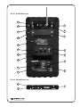
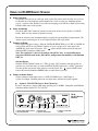
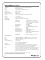
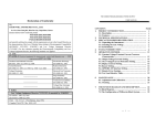
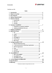
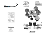
INSTALLATION GUIDE &
USER MANUAL
FM Remote Speaker
Model PPA R1600
RoHS
MAN 135C
FM REMOTE SPEAKER
Model PPA R1600
CONTENTS
PAGE
System Overview . . . . . . . . . . . . . . . . . . . . . . . . . . . . . . . . . . . . . . . . . . . . . . . . . . . . . . . . . . . . . . .2
Cautions & Safety Instructions . . . . . . . . . . . . . . . . . . . . . . . . . . . . . . . . . . . . . . . . . . . . . . . . . . . . .3
Features and Controls . . . . . . . . . . . . . . . . . . . . . . . . . . . . . . . . . . . . . . . . . . . . . . . . . . . . . . . . . . . . . . . . . . . .4
Using the R1600 Speaker . . . . . . . . . . . . . . . . . . . . . . . . . . . . . . . . . . . . . . . . . . . . . . . . . . . . . . . . . . . . . . . . .6
Mounting the R1600 Speaker . . . . . . . . . . . . . . . . . . . . . . . . . . . . . . . . . . . . . . . . . . . . . . . . . . . . . . . . . . . . . .8
Recycling Instructions
. . . . . . . . . . . . . . . . . . . . . . . . . . . . . . . . . . . . . . . . . . . . . . . . . . . . . . . . . . . . .9
Warranty
Specifications
. . . . . . . . . . . . . . . . . . . . . . . . . . . . . . . . . . . . . . . . . . . . . . . . . . . . . . .8
. . . . . . . . . . . . . . . . . . . . . . . . . . . . . . . . . . . . . . . . . . . . . . . . . . . . . . . . . . . . .10
SYSTEM OVERVIEW
Thank you for purchasing the PPA R1600 remote speaker from Williams Sound. The PPA R1600 FM
remote speaker is designed for use with Williams Sound PERSONAL PA™ (PPA) Wide-band FM
Transmitters, 72-76 MHz. With the R1600, small groups of people can listen to the FM broadcast in a
cry room, nursery, office area, or any location where a remote speaker is needed and wiring is
difficult to run.
The R1600 is versatile! It addition to the wireless FM input, the R1600 features a 1/4” mic jack and
line-level input (RCA) jack, all of which can be controlled simultaneously by the front mounted
master volume and tone control knobs, and individually by dedicated and independent volume
controls.
The R1600 supports two independent receiver modules for two channel applications. The internal
mixer combines sound sources flawlessly, and the line-level output provides a simple connection to
recording devices and other sound systems.
The R1600 can be set on a flat surface, threaded on a mic stand, or wall mounted for permanent
installation. Auto/on/off power circuitry ensures that the unit will not be left on accidently.
Note: This equipment has been tested and found to comply with the limits for a Class B digital
device, pursuant to part 15 of the FCC Rules.
2
CAUTIONS AND SAFETY INSTRUCTIONS
CAUTION:
CAUTION:
TO REDUCE THE RISK OF ELECTRIC SHOCK, DO NOT
REMOVE COVER (OR BACK). NO USER-SERVICEABLE PARTS
INSIDE. REFER SERVICING TO QUALIFIED PERSONNEL.
THIS PRODUCT IS DESIGNED TO AMPLIFY SOUNDS TO A HIGH
VOLUME LEVEL. TO PROTECT YOUR HEARING AND THE
HEARING OF OTHERS: MAKE SURE THE VOLUME IS TURNED
DOWN BEFORE TURNING THE SYSTEM ON, THEN ADJUST TO A
COMFORTABLE LISTENING LEVEL. IF YOU EXPERIENCE
FEEDBACK (A SQUEALING OR HOWLING SOUND), REDUCE THE
VOLUME AND MOVE THE MICROPHONE AWAY FROM THE
SPEAKER. DO NOT ALLOW CHILDREN OR OTHER
UNAUTHORIZED PERSONS TO HAVE ACCESS TO THIS PRODUCT.
WARNING: SHOCK HAZARD-DO NOT OPEN.
AVIS: RISQUE DE CHOC ELECTRIQUE-NE PAS OUVRIR.
WARNING:
TO PREVENT FIRE OR SHOCK HAZARD, DO NOT
EXPOSE THIS UNIT TO RAIN OR MOISTURE.
CAUTION:
This powered speaker should be used with either 110-125VAC / 210240VAC - 50Hz/60Hz only. DO NOT use any other power source.
Electrical energy can perform many useful functions. But
improper use can result in potential electrical shock or fire
hazards. This product has been engineered and manufactured to
assure your personal safety. In order not to defeat the built-in
safeguards, observe the following basic rules for its installation,
use and servicing.
ATTENTION:
Follow and obey all warnings and instructions marked
on your speaker and its operating instructions. For safety, please read all the
safety and operating instructions before you operate this speaker and keep
this booklet for future reference.
INSTALLATION
1. Polarization - Your speaker is equipped with a polarized alternating
current line plug (a plug having one blade wider than the other). This
plug will fit into the power outlet only one way. This is a safety feature.
If you are unable to insert the plug fully into the outlet, try reversing
the plug. If the plug should still fail to fit, contact your electrician to
replace your obsolete outlet. Do not defeat the safety purpose of the
polarized plug.
2. Power Sources - Operate your speaker only from the type of power
indicated at the voltage selector switch on the rear panel. If you are not
sure of the type of power supply at your site, consult with the local
power company.
3. Overloading - Do not overload wall outlets, extension cords, or integral
convenience receptacles as this can result in a risk of fire or electrical
shock.
4. Power Cord Protection - Power supply cords should be routed so that
they are not likely to be walked on or pinched by items placed upon or
against them, paying particular attention to cords at plugs or
convenience receptacles.
5. Ventilation - A metal heatsink is provided for heat dissipation. To
ensure reliable operation of the speaker and to protect it from
overheating, this heatsink must not be blocked or covered. Do not place
this speaker in a built-in installation such as a bookcase or rack unless
proper ventilation is provided.
6. Wall Mounting - Mount this speaker to the wall or stand only as
recommended by the manufacturer.
USE
1. Accessories - To avoid personal injury:
• Do not place this speaker on an unstable cart, stand, tripod, bracket, or
table. It may fall, causing serious injury and serious damage to the speaker.
• Use only with a cart, stand, tripod, bracket or table recommended for this
purpose or included by the manufacturer. When using the included
bracket, follow the manufacturer’s instructions for mounting the speaker.
2. Wall or Ceiling Mount - The product should be mounted to the wall or
ceiling only as recommended by the manufacturer.
3. Speaker and Cart Combination - A speaker and cart combination should
be moved with care. Quick stops, excessive force, and uneven surfaces
may cause the speaker and cart combination to overturn.
4. Water and Moisture - Do not use this speaker near or in water or in an
extremely moist environment.
5. Cleaning - Unplug the speaker from the wall outlet before cleaning. Do not
use liquid or aerosol cleaners. Use a damp cloth for cleaning.
6. Heat - Situate the speaker away from heat sources such as radiators, heat
registers or other heat producing items.
7. Attachments - Do not use attachments not recommended by the product
manufacturer as they may cause hazards.
8. Replacement Parts - When replacement parts are required, be sure the
service technician has used replacement parts specified by the
manufacturer or have the same characteristics as the original part.
Unauthorized substitutions may result in fire, electric shock, or other
hazards.
9. Safety Check - Upon completion of any service or repairs to this product,
ask the service technician to perform safety checks to determine that the
product is in proper operating condition.
10. Damage Requiring Service - Unplug this product from the wall outlet
and refer servicing to qualified service personnel under the following
conditions:
a) When the power-supply cord or plug is damaged,
b) If liquid has been spilled, or objects have fallen
into the product,
c) If the product has been exposed to rain or water,
d) If the product does not operate normally by following the operating
instructions. Adjust only those controls that are covered by the operating
instructions as an improper adjustment of other controls may result in
damage and will often require extensive work by a qualified technician to
restore the product to its normal operation,
e) If the product has been dropped or damaged in any way, and
f) When the product exhibits a distinct change in performance - this
indicates a need for service.
NOTE: This equipment has been tested and found to comply with the limits for
a Class B digital device, pursuant to part 15 of the FCC rules. These limits are
designed to provide reasonable protection against harmful interference in a
residential installation. This equipment generates, uses and can radiate radio
frequency energy and, if not installed and used in accordance with the
instruction, may cause harmful interference to radio communications.
However, there is no guarantee that interference will not occur in a particular
installation. If this equipment does cause harmful interference to radio or
television reception, which can be determined by turning the equipment off and
on, the user is encouraged to try to correct the interference by one or more of the
following measures:
• Reorient or relocate the receiving antenna.
• Increase the separation between the equipment and receiver.
• Connect the equipment into an outlet on a circuit different from that
to which the receiver is connected.
• Consult the dealer or an experienced radio/TV technician for help.
3
R1600 FEATURES AND CONTROLS
PPA R1600 REMOTE SPEAKER FEATURES
1. MASTER VOLUME CONTROL - controls the overall volume of the R1600 as well as the LINE OUT (11)
connector.
2. TONE - this is a variable frequency high-cut tone control that is primarily used to reduce high frequency
feedback. The control is essentially flat when turned fully clockwise and reduces more high frequencies as it is
rotated counterclockwise.
3. LED - displays the power state of the speaker. See A2 for details.
4. CHAN A slot - 72-76 MHz wireless FM receiver sled, model SLD 072. Use with an FM transmitter operating
on 72-76 MHz. Williams Sound compatible transmitter models: T35, T27 or T32.
A. ON/OFF/AUDIO LEVEL control - this knob turns the receiver power ON or OFF. Turn knob clockwise to
increase audio input level; counterclockwise to decrease audio input level.
B. CHANNEL SELECTOR - control designates the receiver’s operating frequency. There are 16 channels
available in the 72-76 MHz bandwidth (72.1, 72.2, 72.3, 72.4, 72.5, 72.6, 72.7, 72.8, 72.9, 74.7, 75.3, 75.4, 75.6,
75.7, 75.8, 75.9 MHz). Refer to channel selection chart on page 7 to set the desired operating frequency.
C. RF INDICATOR LED - illuminates RED when an RF signal is present.
D. SQUELCH CONTROL - control silences receiver output when signal strength falls below adjusted level.
Factory set for 25 dB S/N. Adjust with tuning wand, tip size .095 X .016.
E. ANTENNA jack - thread the ANT 028 F-connector antenna on to the receiver here. Antenna telescopes up
to 39” max. height.
5. CHAN B slot - An additional SLD 072 FM receiver sled can be installed here.
6. MIC INPUT - plug a wired dynamic microphone in here. This 1/4 inch jack is designed to accept a low
impedance microphone. The input volume is controlled by the MICROPHONE LEVEL knob (8). This input
does not supply phantom power.
7. OFF/AUTO/ON switch - this controls the power for the speaker after the MASTER AC SWITCH (12) is
placed in the ON position. The speaker is essentially OFF with this switch in the OFF position. The front panel
LED (3) will glow Red. The speaker will come ON from its standby mode automatically when any audio signal
is sensed when the switch is in the AUTO position. The LED (3) will turn from Red to Green. 10 minutes after
all audio stops the speaker will return to its standby mode and the LED (3) will return to Red. The speaker is ON
at all times when the switch is in the ON position. The LED (3) will glow Green.
8. MIC LEVEL - this knob controls the input volume of the microphone plugged into the MIC INPUT (6). It is
always good practice to leave the control turned all the way down (full counterclockwise) when no microphone
is being used.
9. LINE LEVEL - this knob controls the input volume of anything plugged into the LINE IN (10) jack.
10. LINE IN - this mono RCA jack is designed to accept audio from devices such as CD players, video tape players
or anything else with a line-level audio output. The input volume is controlled by the LINE LEVEL knob (9).
11. LINE OUT - this mono RCA jack provides line-level audio to drive additional speakers or other audio devices
with a line-level input. The level is controlled by the MASTER VOLUME CONTROL (1) on the front panel. If
this output is used to drive the LINE IN (10) of a second R1600, the MASTER VOLUME CONTROL (1) will
control the overall volume of both speakers.
12. MASTER AC SWITCH - controls overall power to R1600 speaker.
13. AC JACK - this is where the removable AC plug is attached to the speaker. The AC plug is polarized and will
only attach one way.
14. AC FUSE - the replaceable AC fuse is housed here. Follow the marking on the panel for proper replacement if
needed (0.5A for 210-240VAC use or 1.0A for 110-125VAC use).
15. AC VOLTAGE SELECTOR - set down when used with 110-125VAC (US and other areas) and up when used
with 210-240VAC (Europe and other areas). Be sure to check your local voltage before adjusting the selector.
The speaker is shipped from the factory set in the 110-125VAC position and with a cable designed for that
voltage. Note: The supplied AC cable is to be used for 110-125VAC only.
4
FIG. A1: PPA R1600 REAR VIEW
A
B
4
C
E
D
5
6
8
10
7
11
9
12
13
14
15
FIG. A2: PPA R1600 FRONT VIEW
2
3
1
5
USING THE R1600 REMOTE SPEAKER
SELECT A LOCATION
The R1600 can be placed on a table top, shelf or other flat surface in the listening area; or it can
be threaded on to a microphone stand or mounted on a wall or ceiling (see mounting options,
page 8). A power outlet should be accessible and enough space should be available to run wiring
from the audio source to the speaker.
INSTALL THE ANTENNA
Thread the ANT 028 F-connector antenna on to the back of the receiver speaker (see FIG. B
below). Make sure the antenna is tightened securely.
Extend the antenna to the maximum height by grasping the tip and pulling straight upward. The
antenna can be extended up to 39” max. height and angled 180° up or down.
CONNECT THE POWER
Select the desired power voltage. Slide the VOLTAGE SELECTOR (see 15, FIG. A) DOWN for
110-125VAC and UP for 210-240VAC. Plug the AC power cord into an AC outlet and press the
“POWER ON” switch to the ON position. The “ “ power on LED on the front of the unit will
illuminate RED to indicate standby mode.
Note: The supplied AC cable is to be used for 110-125VAC only. A standard European
plug/cable should be used for the 210-240VAC configuration and should be rated minimum
240V, 5A.
SPEAKER POWER:
Slide the OFF/AUTO/ON switch (see 7, FIG. A) to the “ON” position to turn the speaker on
(speaker stays on all the time). Or, slide the OFF/AUTO/ON switch to the “AUTO” position to
have the speaker turn on only when it detects an audio signal. The “ “ power on LED on the
front of the unit will illuminate GREEN when an audio source is present.
CHOOSE AN AUDIO SOURCE
Choose from three audio input sources: 1) SLD 072 FM Receiver; 2) Mic Input or
3) Line Level Input. Enabling more than one audio source will mix the signals together.
Option 1: SLD 072 FM Receiver Sled (Channel A)
Receiver will pick up a wireless FM signal operating on 72-76 MHz. Compatible with Williams
Sound transmitter models T35, T27 and T32.
FIG. B:
SLD 072 RECEIVER
CONTROLS
1
1. ON/OFF/AUDIO LEVEL CONTROL
2. CHANNEL SELECTOR
6
2
3 4
3. RF INDICATOR
4. SQUELCH ADJUSTMENT
5
5. ANTENNA CONNECTOR,
75 OHMS
Turn on Power: Turn the rotary AUDIO LEVEL CONTROL (see FIG. B)
clockwise to turn the SLD 072 FM receiver ON (you will hear a ‘click’ when the
knob is turned from the OFF position). The “RF” LED indicator will illuminate
RED when an RF signal is present.
FIG. C:
FREQUENCY
SELECTION CHART
Select a Frequency: The R1600 has 16 pre-tuned channels available in the 72–76
MHz bandwidth. Most R1600’s ship from the factory set to switch position 1, or
72.1 MHz (channel A). To change the frequency on the R1600, refer to the
frequency selection chart on the right (FIG. C), then adjust the CHANNEL
SELECTOR (see FIG. B) to the corresponding switch setting. If you experience
FM interference, or if you need to match the transmitter’s frequency, it may be
necessary to change the channel on the R1600.
Important: Make sure your PPA Transmitter (i.e. T35, T27, T32) is on and
has an active audio source. Make sure the R1600 frequency matches your
transmitter frequency!
Adjust the Audio Level: First, make sure the MASTER VOLUME CONTROL on the front of the R1600
(see ① on page 5) is at least 1/4 from max volume. Then rotate the AUDIO LEVEL CONTROL (FIG. B)
clockwise until you can hear the broadcast clearly. If the audio level is too low, it will sound noisy. If the
audio level is too high, it will sound distorted.
Note: The R1600 will have a typical operating range of 1000 feet when used with a PPA T35 transmitter,
500 feet with a T27 transmitter, and 150 feet when used with a T32 transmitter.
Option 2: MIC INPUT
Plug in a dynamic microphone into the 1/4” “MIC INPUT” jack on the back of the speaker.
Note: The R1600 DOES NOT supply phantom power for Electret microphones.
Adjust the Microphone Level: First, make sure the master volume control on the front of the
R1600 is at least 1/4 from max volume. Then rotate the MICROPHONE LEVEL control
clockwise until you hear the broadcast clearly. If the audio input is too low, it will sound noisy.
If the input is too high, it will sound distorted.
Option 3: LINE LEVEL INPUT
Plug in a CD player, tape player, or other audio source into the LINE IN RCA jack on the back
of the speaker.
Adjust the Line In Level: First, make sure the master volume control on the front of the R1600 is
at least 1/4 from max volume. Then rotate the LINE IN LEVEL control clockwise until you hear
the broadcast clearly. If the audio input is too low, it will sound noisy. If the input is too high, it
will sound distorted.
ADJUST MASTER VOLUME
Rotate the VOLUME control on the front of the R1600 until the audio is projecting at a
comfortable listening level.
ADJUST TONE
Rotate the TONE control on the front of the R1600 fully clockwise for a flat frequency response.
Rotate the TONE control fully counterclockwise to cut off the high frequencies.
7
MOUNTING OPTIONS FOR THE R1600 FM REMOTE SPEAKER
WALL MOUNTING
The R1600 is supplied with a wall mounting bracket. It can be attached to the speaker via the built-in
1/4" x 20 threaded holes on the top and bottom of the speaker using the included large screws.
Supplied rubber pads can be applied to the inside surface of the bracket to protect the speaker surface
from scratching and reduce the possibility of the speaker rotating in the bracket. The bracket can be
attached to the desired surface using a number of different fasteners. Be sure to use fasteners that are
appropriate for the surface you are mounting to and that can support the speaker’s weight. Once the
desired position is achieved, tighten the screws securely.
STAND MOUNTING
The R1600 has two industry-standard 5/8" x 27 threaded inserts molded into the cabinet - one on the
bottom and one on the side. These allow the speaker to be securely mounted to a stand (such as a
microphone stand). Be sure to tighten the speaker securely to the stand. Also, be sure that the stand
can support the weight of the speaker and that it will be stable with that weight attached.
FLAT SURFACE
Four self-adhesive anti-skid pads can be applied to the bottom or side of the speaker to help stop it
from moving when placed on a flat surface.
RECYCLING INSTRUCTIONS
Help Williams Sound protect the environment! Please take the time to dispose of your equipment
properly.
Product Recycling Instructions:
Please do NOT dispose of your Williams Sound equipment in the household trash. Please take the
equipment to an electronics recycling center; OR return the product to the factory for proper
disposal.
8
LIMITED WARRANTY
Williams Sound products are engineered, designed, and manufactured under carefully controlled
conditions to provide you with many years of reliable service. Williams Sound warrants the PPA
R1600 against defects in materials and workmanship for FIVE (5) years. During the first five years
from the purchase date, we will promptly repair or replace the PPA R1600.
Microphones, earphones, headphones, batteries, cables, antennas, carry cases, and all other
accessory products carry a 90-day warranty. Chargers carry a 1 year warranty.
WILLIAMS SOUND HAS NO CONTROL OVER THE CONDITIONS UNDER WHICH THIS
PRODUCT IS USED. WILLIAMS SOUND, THEREFORE, DISCLAIMS ALL WARRANTIES
NOT SET FORTH ABOVE, BOTH EXPRESS AND IMPLIED, WITH RESPECT TO THE PPA
R1600, INCLUDING BUT NOT LIMITED TO, ANY IMPLIED WARRANTY OF
MERCHANTABILITY OR FITNESS FOR A PARTICULAR PURPOSE. WILLIAMS SOUND
SHALL NOT BE LIABLE TO ANY PERSON OR ENTITY FOR ANY MEDICAL EXPENSES OR
ANY DIRECT, INCIDENTAL OR CONSEQUENTIAL DAMAGES CAUSED BY ANY USE,
DEFECT, FAILURE OR MALFUNCTIONING OF THE PRODUCT, WHETHER A CLAIM FOR
SUCH DAMAGES IS BASED UPON WARRANTY, CONTRACT, TORT OR OTHERWISE. THE
SOLE REMEDY FOR ANY DEFECT, FAILURE OR MALFUNCTION OF THE PRODUCT IS
REPLACEMENT OF THE PRODUCT. NO PERSON HAS ANY AUTHORITY TO BIND
WILLIAMS SOUND TO ANY REPRESENTATION OR WARRANTY WITH RESPECT TO THE
PPA R1600. UNAUTHORIZED REPAIRS OR MODIFICATIONS WILL VOID THE WARRANTY.
The exclusions and limitations set out above are not intended to, and should not be construed so as to
contravene mandatory provisions of applicable law. If any part or term of this Disclaimer of Warranty
is held to be illegal, unenforceable, or in conflict with applicable law by a court of competent
jurisdiction, the validity of the remaining portions of this Disclaimer of Warranty shall not be
affected, and all rights and obligations shall be construed and enforced as if this Limited Warranty
did not contain the particular part or term held to be invalid.
If you experience difficulty with your system, call for customer assistance:
1-800-843-3544 (U.S.) or +1-952-943-2252 (Outside the U.S.)
If it is necessary to return the system for service, your Customer Service Representative will give you
a Return Authorization Number (RA) and shipping instructions.
Pack the system carefully and send it to:
Williams Sound Corp.
Attn: Repair Dept.
10321 West 70th Street
Eden Prairie, MN 55344 USA
Your warranty becomes effective the date you purchase your system. Your returned warranty card is
our way of knowing when your warranty begins. Please take a moment to fill out and mail the
enclosed card. This information will help us serve you better in the future. Thank you!
9
PPA R1600 SPECIFICATIONS
Dimensions:
12.4"H x 7.1"W x 7.5"D (315mm x 180mm x 190mm)
Color:
Black with white legends
Weight:
9.4lb (4.3kg) approx. with SLD 072 receiver
Rated Power:
20 watts continuous
Frequency Response:
65Hz – 7kHz
Max SPL @ rated output:
101dB @ 1 meter
Woofer:
5.25" (133.35mm) high efficiency magnetically shielded
Tweeter:
1" (25mm) dome
Crossover:
1st order passive @ 8kHz
Tone Control:
-6dB/octave sliding lowpass (3kHz to 8kHz)
Wireless inputs
CHANNEL A:
SLD 072 FM Receiver, 72-76 MHz*
Operating Freq:
72.1, 72.2, 72.3, 72.4, 72.5, 72.6, 72.7,
72.8, 72.9, 74.7, 75.3, 75.4, 75.6, 75.7,
75.8, or 75.9 MHz.
10.7 MHz
+/- 75 kHz max
2 uV at 12 dB SINAD with squelch
defeated
20 mV
65 Hz to 7 kHz +/- 3 dB
60 dB at 100 uV
Thread mount for ANT 028 telescoping
antenna. 75 ohms.
Intermediate Freq:
FM Deviation:
Sensitivity:
Input Overload:
Frequency Response:
Signal to Noise ratio:
Antenna connector:
CHANNEL B:
Empty slot for additional receiver sled
Wired inputs/output
Mic:
-81dBV (0.089mVRMS) for 1 watt 100KΩ unbalanced, 1/4 " phone jack, variable
Line:
-40dBV (10mVRMS) for 1 watt 10KΩ unbalanced, RCA jack, variable
Line-Out:
+15dBV max - RCA jack
AC Power Requirements:
User switchable
110-125 / 210-240VAC - 50Hz / 60Hz
Approvals:
UL, C-UL, FCC, RoHS, WEEE
Included w/speaker:
Removable wall-mount bracket with 2 screws and rubber anti-rotate pads,
removable right-angle AC cord, 4 self-adhesive anti-skid pads, 4 module
screws, 1 noise-canceling circuit boards per receiver sled installed
Note:
This device complies with part 15 of the FCC Rules. Operation is subject to the
following two conditions: (1) This device may not cause harmful interference,
and (2) this device must accept any interference received, including interference
that may cause undesired operation.
*DISCLAIMER: FCC RULES LIMIT USE OF THIS EQUIPMENT TO AUDITORY ASSISTANCE FOR THE HANDICAPPED.
NOTE: SPECIFICATIONS SUBJECT TO CHANGE WITHOUT NOTICE!
10
© 2007, Williams Sound Corp. MAN 135C