1
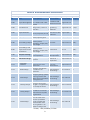
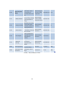
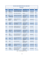
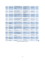
B.E.A.S.T.
[Backpackable-Easily-Assembled-Sustainable-Turbine]
System Design and Project Plan
12 October 2010
Sean Smith
- Mechanical Engineer
- Project Manager
Joshua Gibb
- Mechanical Engineer
Moses Rotich
- Electrical Engineer
Yixiao Zhang
- Electrical Engineer
1
Table of Contents
Background ................................................................................................................................. 3
System Overview ........................................................................................................................ 3
Block Diagram ............................................................................................................................ 4
Functional Description of Blocks ................................................................................................ 5
Organization and Management .................................................................................................... 7
Estimated Budget ........................................................................................................................ 8
Work Breakdown Structure (Fall 2010) ....................................................................................... 9
Work Breakdown Structure (Spring 2011)................................................................................. 11
Gantt Chart (Fall 2010) ............................................................................................................. 13
Gantt Chart (Spring 2011) ......................................................................................................... 14
Network Diagram (Fall 2010) ................................................................................................... 15
Network Diagram (Fall 2011) ................................................................................................... 16
Appendices: Requirements Specification ................................................................................... 17
2
Background
Many of us are dependent upon our small electronics ranging from cell phones to laptops
for functions varying from information gathering to long distance communication. Unfortunately
all of these devices are dependent upon electricity in the form of rechargeable batteries which
only last for a set period of usage time and then depend on a steady source of electricity for
recharging. On extended stays in areas which do not offer an electricity source, an
environmentally-friendly, sustainable, and easily implemented power source is needed.
The BEAST will be a solution to that problem intended specifically for long-term trips
into remote areas and visits to developing nations where a base camp is required. Military
applications and disaster relief efforts are also key markets. The device will consist of a wind
turbine that can fit within or on a hiker’s backpack at a reasonable weight, be easily assembled in
the field with little technical prowess, and supply enough power to efficiently charge cell phone
and laptop batteries.
System Overview
The finished wind turbine will deliver electricity to a NEMA Type B outlet (standard in U.S.
homes) by converting wind energy into mechanical rotational energy and then converting that
mechanical energy into electrical energy. The wind energy will be captured by blades that are
attached to a hub that is free to rotate. The hub will be elevated on a stand such that the lowest
point that the blades spin will be at least 2.14m above the ground. The rotation of the hub will
turn the shaft of an electricity generator and thus convert wind energy into electricity. The
produced electricity will then be stored in a battery and the battery will supply electricity to an
outlet via an inverter. An indicator will tell the user how much power is being produced
instantaneously and how much power is available in the battery. The battery pack will also be
removable for transportation or use away from the turbine.
For the wind turbine to be used the blades must be attached to the hub and the hub must be
attached to the top of a collapsible stand. The stand will have sections that are approximately 1m
in length and when fastened together achieve a height of at least 2.63m. Each section will have
attachment points for tethers that can be attached to the surroundings for stability. The wind
turbine and all of its components will be able to be collapsed into a space no greater than 85
liters and weigh no more than 23 kg.
During high winds the furling mechanism of the wind turbine will automatically turn it out of
the wind so that over-speed of the generator does not occur. Since it may be desirable to
disassemble the wind turbine when the wind is blowing it is recommended that a stick or
provided tool be used to manually turn the turbine out of the wind to aerodynamically brake the
unit.
The turbine will be a complete assembly of the turbine, blades, stand, tethers, battery
pack and circuitry.
3
System Block Diagram
4
Functional Description of Blocks
Stand: Raises the wind-turbine up to more productive winds and keeps the lowest blades at least
2.14 meters off of the ground. The stand provides support in winds up to 20 m/s.
Mechanical Housing: The mechanical housing will protect the user from moving parts such as
gears, while protecting those moving parts from the environment. It will rotate atop the stand
according to the wind direction.
Furling Controller: Limits the effective wind speed acting on the blades by turning the blades
out of the wind up to 90°. This mechanical controller acts as protection against large wind force
and keeps the turbine operating at a safe speed.
Inputs: Wind speed (0-20 m/s) and direction
Outputs: Effective wind speed from 0-15 m/s
Blades: Mounted on the input shaft, the blades convert the effective wind speed into a usable
torque.
Inputs: Effective wind speed from 0-15 m/s
Outputs: 0-750 RPM
Gearing: Increases the initial RPM provided by the blades to an RPM suitable for power
generation at a ratio of 2:1.
Inputs: 0-750 RPM
Outputs: 0-1500 RPM
Generator: A permanent-magnet DC generator which converts the mechanical energy of the
blades into electrical energy.
Inputs: 0-1500 RPM
Outputs: DC power (0-30V, 0-10 A)
Water Resistant Electronics Housing: Provides water resistance to the electronic circuitry.
Charge Controller: Converts and regulates the power coming from the generator into a proper
power for charging the battery. It also prevents charge backflow and calculates the battery
charging rate.
Inputs: DC power (0-30 V, 0-10 A)
Outputs: DC power (13.5-18 V, 0-3.0 A)
5
Charge Rate Indicator: Displays the rate, in watts, at which the charge controller is charging
the battery.
Inputs: DC power (13.5-18 V, 0-3.0 A)
Outputs: Visualization of the charge rate in watts
Battery: A battery which stores at least 200 Wh of energy.
Inputs: DC power (13.5-18 V, 0-3.0 A)
Outputs: DC power (12 V, 0-18 A)
Percent Charged Indicator: Indicates the percent charge available in the battery.
Inputs: Voltage (0-12 V)
Outputs: Visualization of the percent charge available in the battery
On/Off Switch: Determines if the energy available in the battery is to be converted to AC.
Inputs: DC power (0-12 V, 0-3.0 A) and human intervention
Outputs: If the switch is on then 12 V DC will be allowed through, otherwise no current
will be allowed past this point.
Power Inverter: Converts the DC into a usable 125 V AC which is supplied to the user via a
standard outlet.
Inputs: DC power (12 V, 0-18 A)
Outputs: AC power (125 V AC, 0-3 A)
6
Organization and Management
Sean Smith (Mechanical Engineer)
Sean is the project manager and is responsible for ensuring that all of the team
members communicate and that the project is completed on time and within
budget. Parts ordering and any major design changes must be approved by Sean to
ensure that the final product meets the requirement specifications. He is in charge
of the generator selection and gearing. He will work in conjunction with Josh on
the furling mechanism and blades and acts as the secondary engineering for any
component on which Josh is the primary engineer.
Joshua Gibb (Mechanical Engineer)
Josh will be responsible for CAD drawings and simulation of the wind turbine. He
will be in charge of designing and building the housing and stand. He will work in
conjunction with Sean on the furling mechanism and blades and with Moses on
the electronics housing. Due to his practical knowledge, he will be the lead
integration engineer. He is the secondary engineering for any component on
which Sean is the primary engineer.
Moses Rotich (Electrical Engineer)
Moses is responsible for the PCB design for the charge controller and selection of
the inverter. He will work with Josh on the electronics housing and with Yixiao
on the construction and design of any other electrical components of the system.
He is the secondary engineer for any component on which Yixiao is the primary
engineer.
Yixiao Zhang (Electrical Engineer)
Yixiao is responsible for the MULTISIM schematic of the charge controller, the
user interface design and construction, and battery selection. She will work with
Moses on the design and construction of any other electrical system components
as well. She is the secondary engineer for any component on which Moses is the
primary engineer.
All team members will be responsible for contributing equally to all documentation.
Every member is expected to come prepared to contribute to every meeting. Even though each
member is assigned specific tasks, it is important to note that all engineers ought to be familiar
with each other’s system with the integrated unit as a whole in mind.
7
Estimated Costs
Description
Battery
Part Number/
Specifics
SLA battery (12V
18Ah)
6384k344
Set of three
Blades
injection molded
12V Voltage
Regulator,
Charge
Capacitor,
Controller
Resistors
DC to AC Power
DC-AC inverter Inverter
GB 46-315
Electrical Cable
Electrical cable Ties
Receptacle(with
Electrical outlet cover)
Height/OD
(in)
Generator
Housing
Material
Hub Material
Indicator
Steel Spur Gear
443540 PM DC
Generator
6061 Aluminum
Sheet
6060 Aluminum
Sheet
Electricity Power
Monitor
LED indicator
Paracord for
stand ties
Professional
Circuit Board
LED Encasement
Rectifier
Rectifier Diode
Price
0.375
46 in rotor
diameter
Total
1
$40.00
2
$11.24
1
$125.00
$26.00 Amazon.com
1
$26.00
$15.00 Amazon.com
1
$15.00
$16.00 Amazon.com
1
$16.00
2
$19.60
1
$149.00
Lab room
1.17
$9.80 SDP-SI.com
windsteam
$149.00 power.com
24
24
0.125
$48.08 McMaster-Carr
1
$48.08
12
12
0.125
$26.29 McMaster-Carr
1
$26.29
$26.00 Amazon.com
1
$26.00
2
$8.00
2
$7.30
1
$51.00
2.5
3.8
$4.00 Lab room
campingsurvival.
$3.65 com
$51.00 expresspcb.com
$0.98 Amazon.com
6
$5.88
$16.38 McMaster-Carr
1
$16.38
4
$20.40 metalsdepot.com
1
$20.40
0.125
4
$25.52 metalsdepot.com
1
$25.52
0.125
4
$29.44 metalsdepot.com
1
$29.44
Shaft Material 12 O1 Steel
0.25
Tube, Square
1.5
1.5
0.125
Tube, Square
1.75
1.75
Tube, Square
2
2
Total Available
Funds
Current Total
Expenses
Funding Left
Quantity
$5.62 McMaster-Carr
http://www.defen
der.com
100
Circuit Board
Location
$40.00 Amazon.com
Bearing, DS, F
Gears
Width/ID Thickness Length
(in)
(in)
(ft)
$1,000
DS = Double Sealed OD = Outside Diameter
$666.13
$333.87
F = Flanged
8
ID = Inside Diameter
Work Breakdown Structure
Fall 2010
ID
F1.00
F2.00
F3.00
F4.00
F5.00
F6.00
F7.00
F7.10
F7.11
Task
Description
Deliverables
Ens ure that the team i s
Project Management on schedule and under
budget
Keep records of al l
Documentati on
des ign work, research
and tests
Start/Stop
People*
Constrai nts and
Aug 23-Dec 10 S
specificati ons met
Documents.
Engineering
Notebooks
Verbal
Make a fi nal choi ce of
Project Selection
confirmati on with
which proj ect to pursue
profess ors
Techni cal descri ption
Project Specifi cation
Document
of the project's goals
Techni cal Description
of the systems
System Desi gn Report
Document
operation, project pl an,
and budget
Techni cal Description
System Desi gn and
of the systems
Project Pl an Formal
Pres entati on
operation, project pl an,
Presentati on
and budget
Design the
Detail ed desi gn of
Component Design
subcomponents
subcomponents
Detail ed desi gn of
Design of Mechani cal
Mechanical Design
mechani cal
Systems
components
Sel ect a sui tabl e
Product number,
Generator
generator for wind
reas oning,
Selection
generati on
specificati ons
Aug 23-Dec 10 S, J,M,Y
Aug 23-Sept 7
S,J,M,Y
Sept 8 -Sept 28 S,J,M,Y
Sept 29-Oct 12 S,J,M,Y
Oct 14
S,J,M,Y
Sept 29-Nov 30 S,J,M,Y
Sept 29-Nov 30 S,J
Sept 29-Oct 12 S
Blade Design
Design or find blades
sui tabl e for the
generator
Detail ed desi gn,
CAD drawing
Oct 13-Nov 2
S,J
F7.13
Gear Design
Design a gearing system
to bring i ncreas e the
Detail ed desi gn,
RPM's to the rated RPM CAD drawing
of the generator
Nov 3-Nov 16
S
F7.14
Housing Design
Design a housing for
Detail ed desi gn,
the gears and generator
CAD drawing
to sit atop the stand
Nov 17-Nov 30 J
F7.12
F7.15
Furling Design
F7.16
Stand Design
Design a mechanical
controller to l imit the
maximum wi nd speed
of generati on
Design a stand whi ch
wil l raise the windturbine up to better
winds and keep the
lowest bl ades from
passing wi thin 2.14
meters of the ground
Detail ed desi gn,
CAD drawing
Oct 13-Nov 16 S,J
Detail ed desi gn,
CAD drawing
Nov 3-Nov 30
*S-Sean, J-Josh, M-Moses, Y-Yixiao
9
J
F7.20
Electrical System
Design
Design the electrical
system which stores
Detailed design of
and supplies the
electrical system Sept 29-Nov 23 M,Y,J*
generated power to the components
user
Select a light-wieght,
Detailed design,
durable battery capable
product number
Sept 29-Oct 12 Y
of storing 200 Wh of
and specifications
energy
F7.21
Battery Selection
F7.22
Regulates and converts
the generated power
Detailed design,
Charge Controller
into power suitable for schematics
charging the battery
F7.23
Power Inverter
Converts the DC power
Detailed design,
in the battery into 125 V
schematics
AC for the user
Sept 29-Oct 19 M
F7.24
User Interface
Outlet, On/Off Switch,
Charge Rate Indicator,
Charge Amount
Indicator
Oct 27-Nov 9
F7.25
Electronics
Housing
Design a box to protect
the electronic
Detailed design,
components from
CAD drawing
weather
Nov 10-Nov 23 M,J
Detailed design,
schematics
Sept 29-Oct 26 M,Y
Y
F8.00
Final Design Report
Final system and
subsystem design
Document
Nov 9-Dec 7
S,J,M,Y
F9.00
Final Design Formal
Presentation
Presentation of final
design
Presentation
Dec 10
S,J,M,Y
*S-Sean, J-Josh, M-Moses, Y-Yixiao
10
Work Breakdown Structure
Spring 2010
ID
Task
Project
S1.00
Management
Description
Deliverables
Ensure that the team is on
schedule and under budget
Keep records of all design
work, research and tests
Constraints and
specifications met
Documents. Engineering
S2.00 Documentation
Notebooks
Working
Parts
components/meet
S3.00
Assembling of components
Assembly/Testing
specifications
documented
Working
Mechanical
Assembly of mechanical
components/meet
S3.10
Systems
components
specifications
documented
Working
Generator
Test the generator's output components/meet
S3.11
Testing
for given RPM's
specifications
documented
Working
Assemble the gears and
components/meet
S3.12
Gear and Shaft
shaft and test the ratio
specifications
documented
Working
Mechanical
Construct the housing for
components/meet
S3.13
Housing
the gears and generator
specifications
documented
Working
Blade
Construct the blade mount components/meet
S3.14
Mounting
and mount the blades
specifications
documented
Working
Construct the mechanical
components/meet
S3.15
Furling
controller
specifications
documented
Working
S3.16
Stand
Construct the stand
component/meets
specifications
Working
Electrical
Assemble the electrical
components/meet
S3.20
Systems
components
specifications
documented
Working
Construct and ensure that
Charge
components/meet
S3.21
the charge controller
Controller
specifications
outputs steady DC
documented
Sean, J-Josh, M-Moses, Y-Yixiao
11
Start/Stop People*
Jan 18-May 8
S
Jan 18-May 8
S,J,M,Y
Jan 18- Mar 11 S,J,M,Y
Jan 18- Mar 11 S,J
Jan 18-Jan 31
S
Jan 18-Feb 7
S
Feb 8-Feb 21
J
Feb 8-Feb 21
S,J
Feb 12-Mar 11 S,J
Feb 12-Mar 11 J
Jan 18- Mar 11 M,Y,J
Jan 18-Feb 21
M,Y
*S-
S3.22
S3.23
S3.24
S3.25
S4.00
S5.00
S6.00
S7.00
S8.00
S9.00
S10.00
S11.00
Working
Construct and test the
components/meet
Power Inverter conversion from 12 V DC to
specifications
125 V AC
documented
Working
Test the indicators,
components/meet
User Interface
switches, and outlet
specifications
documented
Working
Perform a runtime test on
components/meet
Battery Testing the battery to ensure
specifications
capacity
documented
Working
Construct weather resistant components/meet
Encasement
encasement and test
specifications
documented
Project Status
Present the status of the
Report Formal
Presentation
project
Presentation
System
Combine the components
Complete system
Integration
Test system for technical
System Testing
Fully functioning
specifications; modify as
and Modification
prototype
needed
Acceptance Tests Prove that the device meets
Monitored testing
Complete
specifications
Describes how to use the
User's Manual
device along with any
Document
special considerations
Final report on the
Final Report
Document
prototype
Final Project
Presentation about the
Formal
Presentation
prototype
Presentation
Engineering
Combined presentation of
Presentation
Showcase
prototypes
Sean, J-Josh, M-Moses, Y-Yixiao
12
Jan 18-Feb 7
M*
Feb 8-Feb 28
Y
Feb 14-Feb 28 Y
Mar 1-Mar 11 M,J
Mar 10
S,J,M,Y
Mar 14-Apr 10 S,J,M,Y
Apr 11-Apr 28 S,J,M,Y
Apr 28
S,J,M,Y
Apr 20-May 3
S,J,M,Y
Apr 13-May 3
S,J,M,Y
5-May
S,J,M,Y
8-May
S,J,M,Y
*S-
13
14
15
16
Appendix: Requirements Specification
Backpackable Easily-Assembled, Sustainable Turbine
(BEAST)
Requirements Specification
Sean Smith, Josh Gibb, Moses Rotich, Yixiao Zhang
Overview:
Many of us are dependent upon our small electronics ranging from cell phones to laptops for
functions varying from information gathering to long distance communication. Unfortunately all
of these devices are dependent upon electricity in the form of rechargeable batteries which
only last for a set period of usage time and then depend on a steady source of electricity for
recharging. On extended stays in areas which do not offer an electricity source, an
environmentally-friendly, sustainable, and easily implemented power source is needed. The
BEAST will be a solution to that problem intended specifically for long-term trips into remote
areas and visits to developing nations where a base camp is required. Military applications and
disaster relief efforts are also key markets. The device will consist of a wind turbine that can fit
within or on a hiker’s backpack at a reasonable weight, be easily assembled in the field with
little technical prowess, and supply enough power to efficiently charge cell phone and laptop
batteries.
The Deliverables
1. Working wind turbine
2. System Specifications
1.
Code and electric schematics/MULTISIM
2.
CAD drawing
3
Testing report
4. Users’ manual
5. Final Report
Principles of Operation
The user will assemble the turbine onto a tripod and securely fasten it to the surroundings. The
blades of the windmill will capture energy from available wind and use it to turn an electric
generator. An energy storage device will capture the generated electricity, allowing the
captured energy to be used at the convenience of the user. A standard United States (NEMA
type B) AC outlet (the type typically used in household applications) will be attached to the
17
energy storage device. The charge amount and generation rate will be displayed to the user.
The user can then choose to detach the energy storage device from the turbine and use it offsite or charge their device while the storage device is still attached to the turbine.
Input: The input will be whatever wind energy is available. The system will start generating
given at least a 4 m/s breeze and be able to handle wind gusts up to 20 m/s and then stop
generation in order to protect the internals of the device.
Output: The turbine will be rated to produce at least 15 W given a 6 m/s wind speed at sea
level. The energy storage device will contain at least 200 Wh of energy (enough to charge about
three typical laptops) and an inverter will be used to supply 125 VAC 60Hz through a NEMA
Type B outlet.
Technical Requirements
1.
Power Generation: The generator should produce at least 15 W given a 6 m/s wind
(typical ground level wind speed) and 130 W at 12 m/s (the typical wind speed used to rate
wind turbines).
2.
Power Storage: At least 200 Wh will be stored in a durable and safe energy storage
device. This will provide enough energy to charge three typical 6-cell laptop batteries. The
storage device will be detachable and portable for use away from the turbine.
3.
Electrical Safety: When the storage device is full, electricity will cease being supplied to
the storage device. All wires and circuitry will be able to handle the maximum amount of
current produced by the turbine.
4.
Mechanical Safety: The mechanical parts will be stable and able to withstand the high
shear and bending stresses placed upon them. A housing will cover the gearing and the turbine
in order to protect the user. The lowest point at which the blades spin will be at least 2.14
meters off of the ground.
5.
Portability: The turbine and all of its components should fit within a large backpacking
backpack (85 + liter) and weigh less than 23 kg. It should be easily assembled within an hour
after one practice trial by two individuals who have read the user manual using only basic tools
(screwdriver, wrench, etc.).
6.
Durability: The system will be able to withstand frequent assembly and dis-assembly and
still be operational. The electrical components will be contained in a water-resistant housing.
7.
User Interface: The rate at which the energy is being produced and the amount of charge
available (empty to full) in the energy storage device will be indicated. A 125 VAC 60Hz NEMA
Type B outlet will connect devices to the storage device.
18
Testing Plan:
1. The wind tunnel in the Ulrey will be used to supply a 6 m/s, 12 m/s, and 20 m/s wind speed
to the turbine. The current and voltage going into the battery will be measured at each of those
speeds.
2. The battery will be fully charged and then drained with a run-time test.
3. The wind speed will be increased to 20 m/s to check for mechanical stability of the blades
and hub. A force that simulates the maximum force applied under peak operating
conditions will be manually applied at the hub while the stand is fully assembled and anchored,
in order to check for the stability of the stand.
4. The entire device will be weighed, disassembled, and placed in a backpack. Three separate
groups of two volunteers will assemble the device with any necessary tools supplied. The
average of the completion times of the second attempts must be one hour or less.
5. The device will be assembled and dis-assembled several times to check for durability. The
water resistant electronics housing will be tested while empty by measuring the relative
humidity inside, then spraying it with water, and then measuring the relative humidity again. If
the relative humidity increases by less than 20% relative humidity it passes the test.
6. The indicators will be tested before final installation by measuring known values using
them. A multimeter will be used to verify the outlet’s output while a laptop and a cell phone are
being charged individually.
19