1
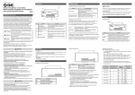
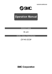
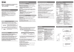
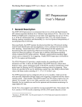
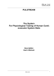
No. : EX##-OMF0012 Technical Specifications Product name : SI Unit Model : EX140-SCS1 EX140-SCS2 Contents 1. Safety ……………………………………………P 2 2. Outline ……………………………………………P 6 3. Applicable solenoid valves ……………………………………………P 6 4. Specifications ……………………………………………P 7 5. Descriptions and Functions ……………………………………………P 8 5-1. LED indication ……………………………………………P 8 5-2. B RATE ……………………………………………P 8 5-3. Address setting ……………………………………………P 9 5-4. Setting of Hold/Clear ……………………………………………P10 6. Wiring ……………………………………………P11 6-1. Communication wiring ……………………………………………P11 6-2. Terminal resistance ……………………………………………P12 6-3. Cable for communication line ……………………………………………P12 6-4. Wiring to power supply ……………………………………………P12 7. Trouble shooting ……………………………………………P13 -1- EX##-OMF0012 1. Safety The SMC SI Unit Save-wire System and this manual contain essential information for the protection of users and others from possible injury and damage to property and to ensure correct handling. Please check that you fully understand the definition of the following messages (signs) before going on to read the text, and always follow the instructions. Also read carefully the instruction manual of relevant equipment or apparatus before use. Indications IMPORTANT MESSAGES Read this manual and follow its instructions. Signal words such as WARNING, CAUTION and NOTE, will be followed by important safety information that must be carefully reviewed. Indicates a potentially hazardous situation which could result in death or serious injury if you do not follow instructions. Indicates a potentially hazardous situation which if not avoided, may result in minor injury or moderate injury. NOTE Gives you helpful information. Operator ♦This operation manual has been written for those who have knowledge of machinery and apparatus that use pneumatic equipment and have full knowledge of assembly, operation and maintenance of such equipment. ♦Please read this operation manual carefully and understand it before assembling, operating or providing maintenance to the SI Unit. Usage Restrictions ♦This product is designed for use in general equipment for factory automation. Never use this product with equipment or apparatus that directly concerns human lives*1, or which malfunction or failure can cause a huge loss. *1: Equipment or apparatus that directly matters human lives means the following: • Medical equipment such as life support systems or equipment used in operating rooms • Compulsory equipment required by law such as the Fire Prevention Law, Construction Law and etc. • Equipment or apparatus that conforms with those mentioned above. ♦Contact our sales department when plans are made for the product to be used for the system*2 including equipment that concerns itself with the safety of persons or that seriously affects the public. This usage needs special consideration*3. *2: The system including equipment that concerns itself with the safety of persons or that seriously affects the public means the following: • Nuclear reactor control systems in nuclear power plants, safety protection systems or other systems important for safety in nuclear power facilities • Driving control systems of mass transportation systems, and flight control systems • Equipment or apparatus that comes into contact with foods or beverages *3: Special consideration means discussing usage with our engineers to establish a safe system designed as fool-proof, fail-safe, redundant and etc. ♦Special consideration of safety or maintainability should be taken to prevent hazard or loss caused by a failure or malfunction that is likely to occur in certain probability due to environmental stress (deterioration). The special consideration means to fully review the equipment or apparatus in design stage and to establish a backup system in advance such as a redundant system or fail-safe system. -2- EX##-OMF0012 ♦Do not disassemble, modify (including change of printed circuit board) or repair. An injury or failure can result. ♦Do not operate the product beyond specification range. Operation at a range that exceeds the specifications can cause a fire, malfunction, or damage to SI Unit. Verify the specifications before use. ♦Do not use the product in an atmosphere containing combustible, explosive or corrosive gas. It can cause a fire, explosion or corrosion. This SI Unit is not designed to be explosion-proof. ♦These instructions must be followed when using the product in an interlocking circuit: • Provide double interlocking by another system such as mechanical protection • Check the product regularly to ensure proper operation Otherwise malfunction can cause an accident. ♦These instructions must be followed while in maintenance: • Turn off the power supply • Stop the supplied air, exhaust the residual pressure and verify the release of air before performing maintenance • Release all energy stored in equipment or devices (hydraulic pressure, mechanical springs, electric capacitors or gravity force), verify the energy is reset to zero, and then perform maintenance work. Otherwise it can cause injury. ♦Perform proper functional checks after maintenance. Stop operation when an abnormality is observed such that the SI unit does not work properly. Safety is not be assured due to unexpected malfunction. -3- EX##-OMF0012 NOTE Follow the instructions given below when selecting and handling your SI Unit: ♦The instructions on selection (installation, wiring, environment of use, adjustment, operation and maintenance) described below must also be followed. ∗Product specifications • Operate SI Unit with the specified voltage. Operation with a voltage beyond specifications can cause malfunction or damage of the unit. • Reserve a space for maintenance Remember to leave space for maintenance when designing layout of the unit. • Do not remove labels. Otherwise error while in maintenance or misreading of an operation manual can cause damage or malfunction. It may also result in nonconformity to safety standards. ♦Instructions on handling ∗Installation • Do not drop, hit or apply excessive shock to the unit. Otherwise it can result in damage to the unit causing failure or malfunction. • Follow the specified tightening torque. Excessive tightening torque can break screws. Refer to “5. Installation and Maintenance” for installation. ∗Wiring (including plugging in/out of connector) • Do not bend or apply tensile force to cables, or apply force by placing heavy load on them. Wiring with bending stress or tensile stress can cause breakage of the cables. • Connect wires and cables correctly. Miswiring can break the SI Unit depending on the miswired circuit . • Do not connect wires while the power is on. Otherwise it can break the SI Unit or I/O devices causing damage or malfunction. • Do not lay wires or cables with power cable or high-voltage cable in the same wiring route. Otherwise the wires to the SI Unit can be contaminated with noise or induced surge voltage from power lines or high-voltage lines causing malfunction. Lay the wires to the SI Unit and each I/O device to a wire duct or in a protective tube other than those for power lines or high- voltage lines. • Verify the insulation of wiring. Poor insulation (interference with other circuit, poor insulation between terminals and etc.) can introduce excess voltage or current to the SI Unit or each I/O device causing damage. • Separate power lines for solenoid valves from power line for Input and control unit. Otherwise wires can be contaminated with noise or induced surge voltage causing malfunction. • Take proper measurements against noise such as noise filter when the SI Unit is incorporated in equipment or devices. Otherwise contamination with noise can cause malfunction. ∗Environment • Select the proper type of protection according to the environment of operation. IP67 protection is achieved when the following conditions are met. 1. To connect units properly with communication line connector and power cable with M12 connector at the both end, and 2. To install Input unit and input block, and SI Unit and manifold valves properly. Use cover or etc. when install in an environment where water always splashes on these units. • Take sufficient shielding measures when install at a following place. Insufficient measures can cause malfunction or failure. Verify the effect of the measures after installation of the unit in equipment or devices: 1. A place where noise due to static electricity is generated 2. A place where electric field strength is high 3. A place where there is radioactive irradiation 4. A place near power line 5. A place where water splashes on the product. -4- EX##-OMF0012 NOTE • Do not use the product near by a place where electric surges are generated. Internal circuit elements of the SI Unit can deteriorate or break when equipment generating a large surge (electromagnetic lifter, high frequency induction furnace, motor, etc.) is located near the SI Unit. Provide surge preventives, and avoid interference. • Use a SI Unit equipped with surge absorber when a surge-generating load such as a relay or solenoid valve is driven directly. Direct drive of a load generating surge voltage can damage SI Unit. • Prevent foreign matter such as remnant of wires from entering this product. Take proper measures for the remnant not to enter the SI Unit in order to prevent failure or malfunction. • Do not expose the SI Unit to vibration and impact. Otherwise it can cause failure or malfunction. • Keep the specified ambient temperature range. Otherwise it can cause malfunction. • Do not use SI Unit in a place where temperature suddenly changes even if it stays within the specified range. • Do not expose the SI Unit to heat radiation from a heat source located nearby. It can cause malfunction. ∗Adjustment and Operation • Use precision screwdriver with small flat blade when setting DIP and rotary switches. ∗Maintenance • Before performing maintenance, make sure to turn of the power supply, stop supplied air, release the residual air in the piping into the atmosphere, and verify that the pneumatic system is open to the air. Otherwise an unexpected operation of a system component can occur. • Perform maintenance and check regularly Otherwise an unexpected malfunction of the system can occur due to a malfunction of the unit. Refer to “5. Installation and Maintenance” the maintenance and checking methods. • Perform a proper functional check. Stop operation when an abnormality is observed such that the device does not work properly. Otherwise an unexpected malfunction of the system component can occur. • Do not use solvents such as benzene, thinner or other to clean the SI Unit. It can damage the surface of the body and erase the indication on the body. Use a soft cloth to remove stains. For heavy stains, use a cloth soaked with diluted neutral detergent and fully squeezed, then wipe up the stains again with a dry cloth. -5- EX##-OMF0012 2. Outline (1) CompoBus/S system Serial transmission system which is composed by OMRON’s PLC (Programmable Logic Controller) SYSMAC series and CompoBus/S master unit. This system makes it possible to connect between master and slave including SI unit by only one cable. (2) SI manifold solenoid valve for CompoBus/S Manifold type solenoid valve which has remote I/O slave (output unit) connected with Compo Bus/S system. The number of occupied output point in SI unit can be selected among 16 and 8. (3) Control of numerous solenoid valves with only one serial transmission cable. SMC’s SI unit allows epoch-making reduction of wires required by direct serial transmission from PLC. (4) High speed communication cycle time Input and output which can have 256 points in 32 slaves at max. are communicated at speed of not more than 1msec per cycle. (5) High flexibility in wiring by the use of T branch and multi drop. Adoption of T branch and multi drop type enables wiring to be arranged freely and extended to 100m at max. (6) Great improvement in ease of maintenance Only one serial transmission cable as signal line eliminates the difficulty of maintenance due to mistake and breakage on wiring. 3. Applicable solenoid valves SQ1000, 2000, SZ3000 -6- EX##-OMF0012 4. Specifications ♦General specification Item SI Unit Ambient temperature Ambient humidity Storage temperature Vibration proof Impact proof Noise immunity Withstand voltage Specification EX140-SCS2 0 to +55°C 35 to 85% RH (No dew condensation) -20 to +65°C 0.5m/s2 (Complying with JIS C0911) 1m/s2 (Complying with JIS C0912) Radiation : ±1000Vp-p, Pulse width 1µs, Pulse on first transition 1ns 1500V AC for 1min. Between external terminal package and ground Insulation resistance 500V DC 2MΩ or more, Between external terminal package and ground Environment Number of occupied output Output type No corrosive gas and no dust is included 16 Points 8 Points Transistor type (Open collector type) 24VDC, solenoid valve with lamp-surge voltage protection circuit of 2.1W or less, SMC product 0. 4VDC or less 14 to 26.4VDC 26.4VDC -5 to +10% Communication power supply 0.1A or less, 24VDC 80g or less EX140-SCS1 Connection load Residual Voltage Communication power supply Solenoid valve power supply Current consumption Weight ♦CompoBus/S system specification Item Applicable PLC Communication Transmission Modulation type Coding type Error control Connection type Distance Specification OMRON Corp. C200HX/HG/HE, C200HS, CQM1 Communication for CompoBus/S 750kbit/s Base band type Manchester symbol type Manchester symbol check, frame length check, parity check T branch, Multi drop Cable type VCTF cable Specific flat cable Trunk 100m or less 30m or less Stay 3m or less 3m or less Total of stay 50m or less 30m or less If the number of connected slave is 16 or less, 50m at max for total stay length is available even specific flat cable. Master type Max. number of I/O C200HW-SRM21 IN128/OUT128 points or IN64/OUT64 points CQM1-SRM21 IN64/OUT64 points, IN32/OUT32 points or IN16/OUT16 points Max. number of I/O <Note> For further information, refer to User’s manual of CompoBus/S available from OMRON Corp. -7- EX##-OMF0012 5. Descriptions and Functions Housing cover NO.2 NO.18 NO.1 NO.17 Switch cover LED PWR. COMM ERR EX140-SCS1 BS+ BDH BDL BS- FG 24V 0V No. Terminal Board 5-1. LED indication LED PWR COMM ERR Content Lights and lights off as power supply for communication is turned on and off respectively. Lights during normal communication and lights off in error or stand-by of communication. Lights when communication error occurs and lights off in normal condition or stand-by of communication. 5-2. B RATE Terminal Connected to MS+ BS+ of communication power line BDH BDH of communication line BDL BDL of communication line BSBS- of communication power line FG Ground line 24V 24V of solenoid valve power line 0V 0V of solenoid valve power line M3 terminal screw in use. -8- EX##-OMF0012 5-3. Address setting (1) ADDRESS NO. (Node address) Setting range of node address depends on type or setting of master as follows. ♦For master unit C200HX/HG/HE or C200HS If max. number of connected slave is 16(IN8/OUT8), the setting range is 0 to 7. If max. number of connected slave is 32(IN16/OUT16), the setting range is 0 to 15. ♦For master unit CQM1 The number of channel occupied by PLC of master unit and the number of point occupied by one node address are related additionally. Number of CH occupied by PLC Number of point occupied by one node address IN1/OUT1 8 IN2/OUT2 8 IN4/OUT4 8 IN1/OUT1 4 IN2/OUT2 4 IN4/OUT4 4 Setting range IN OUT IN OUT IN OUT IN OUT IN OUT IN OUT : 0 to 1 : 0 to 1 : 0 to 3 : 0 to 3 : 0 to 7 : 0 to 7 : 0 to 3 : 0 to 3 : 0 to 7 : 0 to 7 : 0 to 15 : 0 to 15 Max. number of connected slave IN 2 OUT 2 IN 4 OUT 4 IN 8 OUT 8 IN 4 OUT 4 IN 8 OUT 8 IN 16 OUT 16 <Note> • Duplication of node address in different slaves may cause communication error. • 16 points slave is assigned to be made contained into one channel though it occupies 2 slaves with 8 points. Therefore, node address which are not set to the slave are used as follows. If set node address is odd, :Node address with no. just before is also used. If set node address is even : Node address with no. just after is also used. For example, if node address 5 is set to 16 points SI unit (a kind of slave), node address 4 is also used for the SI unit. • For master unit CQM1, if 8 points slave is connected during 4 points mode in it, the slave is considered to occupy points for 2 slaves and node address just after set node address to the slave is also used. If the node address is duplicated with another slave, communication error occurs and makes it impossible to start communication with CompoBus/S. • During 4 points mode, 16 points slave is not available. -9- EX##-OMF0012 (2) Switch setting Open the terminal board cover on the upper section of SI unit and set the DIP switch. 1 ON 0 1 2 3 4 5 6 OFF Node address Hold/Clear ♦Setting of node address In SW1 to 4, setting of node address as follows is required. 0:OFF Node address SW1 SW2 SW3 SW4 Node address SW1 0 0 0 0 0 8 0 1 1 0 0 0 9 1 2 0 1 0 0 10 0 3 1 1 0 0 11 1 4 0 0 1 0 12 0 5 1 0 1 0 13 1 6 0 1 1 0 14 0 7 1 1 1 0 15 1 1:ON SW2 0 0 1 1 0 0 1 1 SW3 0 0 0 0 1 1 1 1 SW4 1 1 1 1 1 1 1 1 5-4 Setting of Hold/Clear This setting is intended to determine whether output of SI unit should be hold or cleared totally when communication error occurs. In SW5, setting becomes available as follows. 0: OFF 1: ON Hold/Clear SW5 Clear 0 Hold 1 <Note> Stay SW6 off in use. - 10 - EX##-OMF0012 6. Wiring 6-1 Communication line There are two connection types are available for slave of CompoBus/S, which are T branch and Multi drop. In T branch, slave is connected to stay branched from trunk and in Multi drop, slave is connected directly to trunk. However, in both types, it is impossible to branch from stay. And to branch stay from trunk, specific crimping connector or commercial terminal base is required. For connection of communication to SI unit, it is necessary to connect BDH and BDL of communication line to BDH and BDL of terminal respectively and also BS+ and BS- of communication power supply to BS+ and BS- of terminal respectively. Crimping connector for branch Master Unit BDH Terminal Resistanse BDL Stabilized power supply Specific flat cable BS+ BDH BDL BS- FG 24V 0V BS+ BDH BDL BS- FG 24V 0V SI Unit SI Unit Class 3 Stabilized ground power supply Class 3 Stabilized ground power supply This SI unit is multi power supply type slave and equips two separate power ports for communication and solenoid valve. The port for communication can be supplied through specific flat cable, but one for solenoid valve can’t and needs separate power supply. And the separate power supply can give the power to the port for communication. Wiring order in specific flat cable for communication power supply and line is specified as follows. Power supply+ (BS+) Brown Line High (BDH) Black Line Low (BDL) White Power supply- (BS-) Blue To protect the system from noise effect, separate cable for communication from power line and high voltage line. And mind that incorrect wiring order may damage SI unit and peripheral equipment. - 11 - EX##-OMF0012 6-2 Terminal resistance For stable communication, terminal resistance needs to be mounted to the trunk end located in opposite side of master (i.e. the most far end from master). And in use, the terminal resistance shall be prepared from OMRON Corp. with reference below. SRS1-T Terminal base with terminal resistance. Available in both VCTF and specific flat cable. SCN1-TH4T Crimping connector with terminal resistance. Available in only specific flat cable. For connection of communication cable to terminal base with terminal resistance, it is necessary to connect BDH and BDL of communication line to adequate each of terminal. If the slave at the trunk end is connected in T branch, it is necessary to connect terminal resistance by the cable longer than length of stay branched from trunk so that the terminal resistance would be positioned the most far from master. 6-3 Cable for communication line Type Specification VCTF cable (available on the market) Vinyl code VCTF JIS C3306 2 cores, Nominal section 0.75mm2 (Signal line × 2) Conductor resistance(at 20°C) : 25.1Ω/km Specific flat cable SCA1-4F10 (100m) Nominal section 0.75mm2 × 4 (Signal line × 2, Power line × 2) Ambient temp. : 60°C or less. 6-4 Wiring to power supply This SI unit is multi power supply type slave and has two power ports for communication and solenoid valve. (1) Power supply for communication • If VCTF is used in communication line, power is supplied for SI unit by different cable. • If specific flat cable is used in communication line, power is supplied for SI unit by the flat cable. (2) Power supply for solenoid valve Power supply DC24V, -5%, +10% needs to be prepared and connected. The power supply and used cable shall be selected with consideration of current consumption of solenoid valve and SI unit. This power supply can give the power for communication of SI unit. <Note> The separate power supply should have margin in its capacity enough for rush current at start. Insulate the core of specific flat cable unused for supply of power at its end. - 12 - EX##-OMF0012 7. Troubleshooting Following is flow chart to eliminate the cause of operating failure in SI unit. For troubleshooting for whole system, refer to User’s manual for CompoBus/S available from OMRON Corp. The solenoid valve doesn’t operate. LED on solenoid valve lights? YES Contact SMC. NO NO PWR LED lights? Power for communication is supplied? NO Supply the power for communication. YES COMM LED lights? YES Node address is set correctly? NO Correct setting of node address. NO YES Check the ERR LED indication, serring of PLC, program and wiring. Refer to the OMRON Corp. User’s manual, etc. for details. Even after that, the normal condition can’t be obtained, please contact SMC. YES Power for solenoid valve (24VDC) is supplied? - 13 - NO Supply the power for solenoid valve (24VDC). EX##-OMF0012