1
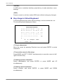
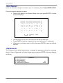
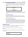
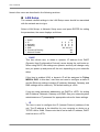
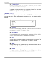
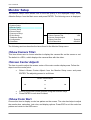
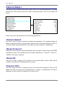
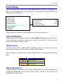
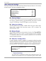
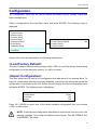
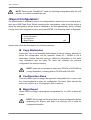
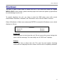
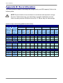
Triplex MPEG-4 DVR OSD Setup Guide 00940A01 Version 1.1 00940A01 User’s Manual Table of Content Menu System Overview.....................................................................................................5 <Key Usage> ................................................................................................................5 Key Usage in OSD Menu .......................................................................5 Key Usage in Virtual Keyboard...............................................................6 System Setup .....................................................................................................................8 <Version> .....................................................................................................................8 Hardware Version...................................................................................8 Software Version ....................................................................................8 Software Upgrade via Local Device .......................................................9 <Language> .................................................................................................................9 <Date / Time> .............................................................................................................10 Date / Time Setting...............................................................................10 Date / Time Display ..............................................................................10 Date Display Mode ...............................................................................10 Time Display Mode............................................................................... 11 Date/Time Order................................................................................... 11 Daylight Saving Time............................................................................ 11 DST Start / End .................................................................................... 11 DST Bias .............................................................................................. 11 <Unit Name> ..............................................................................................................12 <Password>................................................................................................................12 Admin / User Password ........................................................................13 Enable Password .................................................................................13 Load Factory Password........................................................................13 <Network Setup> ........................................................................................................13 LAN Setup ............................................................................................14 - DHCP......................................................................................14 IP ............................................................................................14 Netmask..................................................................................15 Gateway..................................................................................15 DNS ........................................................................................15 Connect At Booting .................................................................15 Network Restart ......................................................................15 Trigger Port...........................................................................................16 <RS485 Setup> ..........................................................................................................16 Unit ID ..................................................................................................16 2 Baud Rate ............................................................................................16 User’s Manual Bits .......................................................................................................16 Stop ......................................................................................................16 Parity ....................................................................................................16 <Key Beep>................................................................................................................17 Monitor Setup...................................................................................................................18 <Show Camera Title> .................................................................................................18 <Screen Center Adjust>..............................................................................................18 <Show Color Bar> ......................................................................................................18 <VGA Resolution> ......................................................................................................19 Camera Setup >................................................................................................................20 <Camera Select>........................................................................................................20 <Dome Protocol>........................................................................................................20 <Dome ID> .................................................................................................................20 <Camera Title> ...........................................................................................................20 <Covert>.....................................................................................................................21 <Brightness> ..............................................................................................................21 <Contrast>..................................................................................................................22 <Saturation> ...............................................................................................................22 <Hue>.........................................................................................................................22 Record Setup ...................................................................................................................23 <Record Mode>..........................................................................................................23 <Schedule Setup> ......................................................................................................24 Day/ Night Time Start ...........................................................................24 Day / Night Time End ...........................................................................24 Weekend Schedule ..............................................................................24 Weekend Start/ End .............................................................................24 <Preset Record Configuration> ..................................................................................25 <ezRecord Setup>......................................................................................................26 <Circular Recording>..................................................................................................27 <Purge Data> .............................................................................................................27 Purge All Data ......................................................................................27 Purge All Event Data ............................................................................27 Purge Event Before ..............................................................................28 Start to Purge .......................................................................................28 Sequence Setup...............................................................................................................29 <Main Monitor Dwell> .................................................................................................29 <Main Monitor Schedule>...........................................................................................29 Event Setup ......................................................................................................................31 <Internal Buzzer> .......................................................................................................31 <Event Icon> ..............................................................................................................31 3 User’s Manual <Event Duration>........................................................................................................31 <Per Channel Config> ................................................................................................32 Channel Select .....................................................................................32 Video Loss Detect ................................................................................32 Motion Detect .......................................................................................32 Detection Configuration........................................................................32 - Detected Area Setup...............................................................32 Sensitivity................................................................................33 Block Threshold ......................................................................33 Alarm In ................................................................................................33 Alarm Out .............................................................................................33 Database Setup ................................................................................................................35 <Total / Free Size of HDD> .........................................................................................35 <Internal / External Disks>..........................................................................................35 Configuration ...................................................................................................................37 <Load Factory Default> ..............................................................................................37 <Import Configuration> ...............................................................................................37 <Export Configuration>...............................................................................................38 Copy Destination ..................................................................................38 Configuration Name .............................................................................38 Begin Export.........................................................................................38 Shutdown..........................................................................................................................39 Appendix A: Technical Specifications ...........................................................................40 Appendix A: Technical Specifications ...........................................................................40 Appendix B: Record Duration.........................................................................................42 4 User’s Manual Menu System Overview The detailed functions and settings of Triplex MPEG-4 DVR can be set using the hierarchical OSD menu. This chapter particularizes the items and options in the OSD menu. To enter the Main menu, press MENU and then enter Administrator or User password. The default passwords are shown in the following table. The same default passwords are used for entering the remote viewing software, DVRRemote. Administrator Password User Password 1234 4321 It is strongly suggested to change the passwords to prevent unauthorized access to the unit. After entering the correct password, the Main menu is displayed. Main Menu 1. System Setup 2. Monitor Setup 3. Camera Setup 4. Record Setup 5. Sequence Setup 6. Event Setup 7. Database Setup 8. Configuration 9. Shutdown <Key Usage> The key usage differs under the OSD Setup Menu and in the Virtual keyboard, which can be seen while setting some items, such as Unit Name and IP Address, in the OSD Setup Menu. Key Usage in OSD Menu Below introduce some keys used frequently to set up the unit via the OSD Setup Menu. <Direction Keys> In the OSD menu, Direction keys are used to move the cursor to previous or next fields. UP / DOWN are used to change the value in the selected field. 5 User’s Manual <ENTER> In OSD menu or selection interface, press the key to make selection or save settings. <ESC> Press to cancel or exit from certain OSD menu without saving any changes. Key Usage in Virtual Keyboard A virtual keyboard shows when edit the settings, such as camera title, etc. The virtual keyboard displays as follows. A B C D E F G H I K L M N O P Q R S T U V W X Y Z a b c d e f g h i j k l m n o p q r s t u v w x y z 0 1 2 3 4 5 6 7 8 9 . ! @ # − _ ◄ ► Cancel Backspace J Delete OK <To input characters> Move the cursor by pressing Direction keys and press ENTER to select characters. <To move the cursor in title entry> Press MODE and LEFT / RIGHT simultaneously to move the cursor to left / right in the title entry. <To delete previous character> Select <Backspace> and press ENTER, or press MODE and UP simultaneously. <To delete current character> Select <Delete> and press ENTER, or press MODE and DOWN simultaneously. 6 User’s Manual <To exit the virtual keyboard> Select <OK> and press ENTER to save the settings and exit, or press ESC to exit without saving changes 7 User’s Manual System Setup Select <System Setup> from the Main Menu and press ENTER to enter the System Setup menu. Main Menu 1. System Setup 2. Monitor Setup 3. Camera Setup 4. Record Setup 5. Sequence Setup 6. Event Setup 7. Database Setup 8. Configuration 9. Shutdown System Setup 1. Version 2. Language 3. Date/Time 4. Unit Name 5. Password 6. Network Setup 7. RS485 Setup 8. Key Beep English DVR-A10 YES The items in the System Setup menu are described in the following sections. <Version> The Version menu allows user to view system information such as hardware and software version. From the System Setup menu, select <Version> and press ENTER. The following menu is displayed. The first three items, including <Model Name>, <Hardware> and <Software>, are for read only, which CANNOT be changed. Version Model Name Hardware Software Software Upgrade via Local Device ***** **.**.** ***.***.***.*** The items in this menu are described in the following subsections. Hardware Version The item identifies the hardware version for this unit. Software Version The item identifies the software version installed on this unit. 8 User’s Manual Software Upgrade via Local Device This item is used for updating the Triplex MPEG-4 DVR software by local device. The menu is displayed as follows. Software Upgrade via Local Device Upgrade Version xxxx-xxxx-xxxx-xxxx Select NO Connect an USB drive contains upgrade software to the unit; the available upgrade files will be listed in the menu. To update the system, select a file and use UP / DOWN keys to choose <YES>. Press ENTER to confirm the selection and start the upgrade process. The Triplex MPEG-4 DVR uploads the software, updates the system files, and reboots automatically. The upgrade may take several minutes to save the changes in the memory of the system. After reboot the unit, please check the software version again. NOTE: No power interruption is allowed during the software update. Ensure that no power interruption can occur until the unit is completely rebooted. NOTE: Do not remove the external USB ThumbDrive®/CD-ROM before the unit has completely shut down (hard drive and fan are off). Removing the external USB ThumbDrive®/CD-ROM before shut down can cause the system to update improperly. <Language> The Language item allows user to select the language for the OSD menu and screen messages. Language selection takes effect immediately when the selection is done. Press ENTER and then press UP / DOWN to select from listed languages and press ENTER to confirm. 9 User’s Manual <Date / Time> User can set the current date, time and other OSD parameters in this menu. The Administrator’s privileges are required for entering the submenu. In System Setup menu, select <Date/Time> and press ENTER; the Date/Time menu displays as follows. Date/Time 1. Date 2. Time 3. Date/Time Display 4. Date Display Mode 5. Time Display Mode 6. Date/Time Order 7. Daylight Saving Time 8. DST Start 9. DST End 10. DST Bias 2005/02/21 PM10:39:26 1 Row Y/M/D 24 HR Date First OFF Apr, 1 st Sun, 02:00 Apr, Last Sun, 02:00 60 Min NOTE: The reset date / time setting applies to record new video, the date and time of previously recorded video will not be changed. NOTE: To avoid record database corruption, after changed Date/Time setting, clear the database is recommended. Date / Time Setting Select <Date> or <Time> and press ENTER for adjusting the settings. LEFT / RIGHT keys are used to move the cursor to previous or next field, ENTER is for selecting, and UP / DOWN are used to change the value in the selected field. Date / Time Display Users are allowed to choose to set the date / time OSD displays in 1 or 2 rows. Use the UP / DOWN keys to change the setting. The default is to display the date / time OSD in one row. Date Display Mode This function allows user to set the OSD display type of the date / time. There are three options to select from: <Y/M/D>, <M/D/Y> or <D/M/Y>. “Y” represents “Year”, “M” represents “Month” and “D” represents “Day”. Use UP / DOWN keys to change the setting. The default setting is <Y/M/D> in both NTSC / PAL formats. 10 User’s Manual Time Display Mode User can choose to set the time format to <12 hour> or <24 hour>. Use the UP / DOWN keys to change the format. The default setting is <24 hour>. Date/Time Order The item is used to set the order of Date/Time display to <Date First> or <Time First>. Select this item and press ENTER, then use UP / DOWN keys to change the setting. Daylight Saving Time The item is for people who live in certain regions to observe Daylight Saving Time. Select <ON> to enable, or <OFF> to disable the function. If the function is disabled, the DST Start / End time and DST Bias will be grayed out and cannot be accessed. If this function is enabled, the date/time information will be shown on the screen with a DST icon when playing back recorded video or searching video in the event list. “S” indicates summer time and “W” indicates wintertime. DST Start / End The items are used to set the daylight saving duration. Use LEFT / RIGHT to move the cursor to the next or previous field, UP / DOWN to change the settings. DST Bias The item allows user to set the amount of time to move forward from the standard time for daylight saving time. Available options are <30>, <60>, <90> and <120> minutes. 11 User’s Manual <Unit Name> Users are allowed to assign a unit name, up to 11 characters, to the Triplex MPEG-4 DVR. Follow the steps to edit the unit name. • Select <Unit Name> from System Setup menu and press ENTER. A virtual keyboard displays. Unit Name A B C D E F G H I K L M N O P Q R S T U V W X Y Z a b c d e f g h i j k l m n o p q r s t u v w x y z 0 1 2 3 4 5 6 7 8 9 . ! @ # − _ ◄ ► Backspace Cancel J Delete OK • • Use Direction keys to move the cursor to the wanted character. Press ENTER to add the character to the entry field (up to 11 characters). • When done, move the cursor to <OK> and press ENTER to save the settings and exit. <Password> The Password menu allows administrator to change the password settings for accessing the unit. Select <Password> in System Setup menu and press ENTER; the menu displays as follows. Password 1. Admin Password 2. User Password 3. Enable Password 4. Load Factory Password 12 No None User’s Manual Admin / User Password Only the administrator is allowed to change the user and administrator password to any 4~8 digit number. Use the UP / DOWN Direction keys to select the desired account and press ENTER, the following menu is displayed. Admin Password ________ Press Channel Keys To Enter Password (4-8 Digits) Press ◄ To Delete Use CHANNEL keys to input the new password and confirm the new password. After setting the new password, press ENTER to save the settings and exit. Enable Password The item is used to determine if the password is required for accessing the OSD menu. Select <YES> to demand entering password when accessing the OSD menu; if not, select <NO>. Load Factory Password This item allows the administrator to reload the factory password in case that the administrator cannot remember the password. There are three options to select from: <Admin> (reload the Admin password only), <User> (reload the User password only), and <All> (reload the Admin and User passwords) and <None>. The factory password is 1234 for administrator and 4321 for user. <Network Setup> The Network Setup menu allows the administrator to configure the network by specifying the network related settings, such as IP address and Netmask, etc. See your network administrator and/or network service provider for more specific information. From the System Setup menu, select <Network Setup> and press ENTER. The following menu displays. Network Setup 1. LAN Setup 2. Trigger Port 80 13 User’s Manual Items in this menu are described in the following sections. LAN Setup The network related settings in the LAN Setup menu should be associated with the network service type. Select <LAN Setup> in Network Setup menu and press ENTER for setting the parameters; the menu displays as follows. LAN Setup 1. DHCP 2. IP 3. Netmask 4. Gateway 5. DNS 6. Connect At Booting 7. Network Restart ON 0 .0 .0 .0 0 .0 .0 .0 0 .0 .0 .0 192.168.10.1 Yes No - DHCP This item allows user to obtain a dynamic IP address from DHCP (Dynamic Host Configuration Protocol) server during the unit boots up. When using DHCP, the settings are dynamic and they will change every time you power up and power off the unit; depending on your network's setup. If the item is enabled (ON), a dynamic IP will be assigned to Triplex MPEG-4 DVR. In this case, user does not need to configure a static IP and the Ethernet settings including IP address, Netmask, Gateway, and DNS settings will be read-only. The default setting is <ON>. If you are using permanent addressing, set DHCP to <OFF> for setting the IP Address, Netmask, Gateway, and DNS. See your network system administrators or IT personnel for appropriate values for these settings. - IP The item is used to configure the IP (Internet Protocol) address of the unit. The IP address is the identifier for your computer or device on a TCP/IP LAN or WAN. Please note that to set a static IP address, DHCP must be set to <OFF>. 14 User’s Manual - Netmask A netmask is a 32-bit mask used to divide an IP address into subnets and specify the networks available hosts. Its value is defined by your network administrator. It takes the form as ***.***.***.***, for example, 255.255.255.255. This item allows user to enter the value of the Netmask for the unit. Please note that to configure the item, DHCP must be set to <OFF>. - Gateway Gateway is a node on a network that serves as an entrance to another network. Users are allowed to specify the IP address of the gateway or router associated with this unit. To configure this item, DHCP must be set to <OFF>. - DNS DNS is the abbreviation for “Domain Name Server”, which is an Internet service that translates domain names into IP addresses. Because domain names are easier to remember. The item allows user to specify the IP address of the Domain Name System associated with the unit. To configure this item, DHCP must be set to <OFF>. If the server is unavailable when using DHCP, the unit searches for the network server and boots up more slowly. This network search continues until it times out. - Connect At Booting The unit is allowed to connect to the internet automatically when powered up. Select <YES> to connect at booting, otherwise select <NO>. The default setting is <YES>. - Network Restart Network restart is required after changing network settings. Select <YES> to restart the network device. 15 User’s Manual Trigger Port To avoid the default service port (port 80) to be blocked, the item enables user to change port 80 into another port. To change the trigger port, move the cursor over <Trigger Port> and press ENTER, then adjust the setting by UP / DOWN keys. <RS485 Setup> This menu allows setting up the parameters of the unit’s RS-485 communications port. From the Main menu, select <RS485 Setup> and press ENTER. The following menu is displayed. RS485 Setup 1. Unit ID 2. Baud Rate 3. Bits 4. Stop 5. Parity 224 9600 8 1 None Unit ID This item is used to change the RS-485 ID address of the unit. The ID is in the range of <1> to <255>. The default is <224>. Baud Rate The Baud rate options for associated with the protocol are <2400>, <4800>, <9600>, <19200> and <38400>. The default is <9600> baud. Bits User can specify the bits in a word that are associated with this protocol. The available options are <6>, <7> and <8> bits. The default is <8> bits. Stop User can specify the stop bit associated with this protocol. Options are <1> and <2> stop bits. The default is <1> stop bit. Parity This item is used to specify the parity associated with this protocol. Options are <ODD>, <EVEN>, and <NONE>. The default is <NONE>. 16 User’s Manual <Key Beep> The item is used to enable or disable the key tone. Select <YES> to enable the key tone, or <NO> to disable. 17 User’s Manual Monitor Setup The Monitor Setup menu allows user to tune the quality of the displayed image. Select <Monitor Setup> from the Main menu and press ENTER. The following menu is displayed. Main Menu 1. System Setup 2. Monitor Setup 3. Camera Setup 4. Record Setup 5. Sequence Setup 6. Event Setup 7. Database Setup 8. Configuration 9. Shutdown Monitor Setup 1. Show Camera Title 2. Screen Center Adjust 3. Show Color Bar 4. VGA Resolution YES Execute 800x600 The following sections describe the items found in the Monitor Setup menu. <Show Camera Title> This item allows user to choose whether to display the camera title on the screen or not. The default is <YES>, which displays the camera titles with the video. <Screen Center Adjust> The item is used to adjust the screen center of the main monitor display area. Follow the steps to set the center point. • Select <Screen Center Adjust> from the Monitor Setup menu and press ENTER. The adjusting screen is as follows. Screen Center Adjust ▲ ◄ + ► ▼ • • Position the screen center position using the Direction keys. Press ENTER to exit when finished. <Show Color Bar> Choose this item to display a color bar pattern on the screen. The color bar helps to adjust the monitor hue, saturation, text color, and display options. Press ESC to exit the color bar pattern and return to the OSD menu. 18 User’s Manual <VGA Resolution> The item allows user to select appropriate VGA resolution for the VGA monitor connected to the unit. The options are <800×600> (default), <1024×768> and <1280× 1024>. NOTE: If the selected VGA resolution is too high for the monitor, the message “No Signal’’ will be shown on screen. Then please press ESC on the front panel to restore the original setting. 19 User’s Manual Camera Setup > The items in the Camera Setup menu enable user to set camera parameters, including camera title, dome protocol and ID for each connected camera. The menu is shown as below. Main Menu 1. System Setup 2. Monitor Setup 3. Camera Setup 4. Record Setup 5. Sequence Setup 6. Event Setup 7. Database Setup 8. Configuration 9. Shutdown Camera Setup 1. Camera Select 2. Dome Protocol 3. Dome ID 4. Camera Title 5. Covert 6. Brightness 7. Contrast 8. Saturation 9. Hue CH3 None 0 CH3 No 0 0 0 0 Items in this menu are described in the following subsections. <Camera Select> The item is used to select a camera for setting the parameters. The related settings will follow the selected camera, such as dome protocol and camera title. Move the cursor to <Camera Select> and press ENTER, then select a channel using UP / DOWN keys. <Dome Protocol> Select the communications protocol associated with your dome camera using the ENTER and Direction keys. The available protocol includes <DynaColor>, <Pelco D>, <Pelco P>, <AD422> and <None> (default). <Dome ID> This item is used to assign an ID number to the selected dome camera. Note that ID number must match the ID address set by the dome. <Camera Title> This item allows the user to change the title of each camera connected to the unit. By default, the titles of cameras are numbered from 1 through 16 respectively. The title is displayed on screen after the changes of the titles are set. 20 User’s Manual Follow these steps to enter a new title for a camera. • In the Camera setup Menu, move the cursor to Camera Title and press ENTER. A virtual keyboard with alphanumeric characters is displayed. Camera Title A B C D E F G H I K L M N O P Q R S T U V W X Y Z a b c d e f g h i j k l m n o p q r s t u v w x y z 0 1 2 3 4 5 6 7 8 9 . ! @ # − _ ◄ ► Cancel Backspace J Delete OK • Use Direction keys to position the cursor in the title entry field above the virtual keyboard. • Use Direction keys to move the cursor through the lists of characters to the one you need. Press ENTER to select a character. Continue until the name is established. Each title can contain up to 11 characters in it. • After title entry is finished, move the cursor to <OK> and press ENTER; otherwise, either press ESC, or move the cursor to <Cancel> and press ENTER to abort. <Covert> This function allows user to choose certain camera to be covert while the unit is continuing recording video. Choosing <YES> means to cover the selected camera; and <NO> to remain the selected camera non-covert. The default setting is <NO>. To make a camera be covert, follow these steps: • Select the channel that you want it to be covert from the <Channel Select> item. • After selecting the channel, move the cursor to <Covert> item and select <YES>. <Brightness> Move the cursor to the item and press ENTER for adjusting the brightness of the camera. Use UP / DOWN keys to adjust the numeric value. The range of brightness values is <-128> to <127>. The default setting is <0>. 21 User’s Manual <Contrast> Move the cursor to the item and press ENTER for adjusting the contrast of the camera. Use UP / DOWN keys to adjust the value. <Saturation> Move the cursor to the item and press ENTER to adjust the color saturation of the camera using UP / DOWN keys. This value will be ignored on monochrome monitors. The range of saturation values is <-128> to <127>. The default setting is <0>. <Hue> Move the cursor to the item and press ENTER for adjusting the hue of the camera. Use UP / DOWN keys to adjust the value. 22 User’s Manual Record Setup The following three factors will effect the total record time of Triplex MPEG-4 DVR: • • HDD capacity Recording Rate (Picture per Second) • Image quality settings The greater the recording rate and the higher the quality setting, the shorter the recording time. Most of the related factors can be set here in this submenu. The Record Setup menu allows user to set recording quality, recording schedules, and other recording parameters. Administrator's password is required to access Record Setup menu. In the Main menu, move the cursor to <Record Setup> and press ENTER. The following menu is displayed. Main Menu 1. System Setup 2. Monitor Setup 3. Camera Setup 4. Record Setup 5. Sequence Setup 6. Event Setup 7. Database Setup 8. Configuration 9. Shutdown Record Setup 1. Record Mode 720× ×240@120PPS 2. Schedule Setup 3. Preset Config Standard 4. esRecord Setup 5. Circular Recording ON 6. Purge Data <Record Mode> The item is for selecting resolution and recording rate. The relative record settings, such as preset configuration, will follow the record mode setting. The options are <720 × 480@30PPS>, <720 × 240@60PPS> and <360 × 240@120PPS> in NTSC (<720 × 576@25PPS>, <720× ×288@50PPS>, <360× ×288@100PPS>in PAL). Move the cursor to this item and press ENTER, then select a Record mode using UP / DOWN keys. NOTE: After changing the Record Mode setting, the warning message “This will FORMAT ALL HARDDISKS and LOAD THE FACTORY DEFAULT CONFIG!” will be shown on the screen. Press ENTER to confirm the selection, then the unit starts to format the hard disks and load the factory default settings, or press ESC to abort. 23 User’s Manual We strongly recommend to backup your programmed configuration before making any changes on Record Mode settings. <Schedule Setup> This submenu is used to set the day and night time, or weekend recording schedule. The Night and Day schedules are used to define daytime and nighttime; the Weekend schedule is tailored for weekends and holidays. Select <Schedule Setup> from the Record Setup menu and press ENTER; the following menu is displayed. Schedule Setup 1. Day Time Start 2. Day Time End 3. Night Time Start 4. Night Time End 5. Weekend Schedule 6. Weekend Start 7. Weekend End AM PM AM PM 06:00 18:00 06:00 18:00 YES Fri 18:00 Mon 06:00 Day/ Night Time Start The Day/Night Start Time determines the beginning of day/night recording time. The time is indicated in 1-minute increments. The time display format in this menu is based on the setting of Time Display Mode. Day / Night Time End The Day/Night End Time determines the end point of day/night recording time. The time is indicated in 1-minute increments. The time display format in this menu is based on the setting of Time Display Mode. Weekend Schedule The Weekend Schedule determines whether a weekend schedule is in effect. Choose <YES> to take effect the related weekend settings. Weekend Start/ End The Weekend Start Time indicates the specific day and time that a weekend begins, for example, FRI 18:00. The Weekend End Time indicates the specific time and day that a weekend ends, for example, MON 06:00. Time is indicated in 1-minute increments. Note that the value you have set indicates when the regular Day and Night scheduling ends, and Weekend recording begins. 24 User’s Manual <Preset Record Configuration> The <Preset Config> is used to select the preset recording quality and frame rate. Different default recording quality levels are offered for user to choose: <Best Quality>, <Standard>, <Extended Record>, <ezRecord >, <512Kbps DSL>, <256Kbps DSL> and <128Kbps DSL>. According to various Record modes, the preset configuration options for normal and event status are described in terms of relative recording rate (PPS) and recording size for each channel in the table below. These preset conditions override any other quality and rate settings. The default Preset Configuration setting is <Standard>. Record Mode: Full-D1 mode (NTSC: 720× ×480@30PPS) (PAL: 720× ×576@25PPS) Preset Normal PPS Normal Size Event Event Configuration PPS Size 3.75 NTSC 15 NTSC Best Quality 20 KB 20 KB (3.125 PAL) (12.5 PAL) Standard 3.75 NTSC 15 NTSC 14 KB 20 KB (Default) (3.125 PAL) (12.5 PAL) ezRecord Auto Extended Record 3.75 NTSC (3.125 PAL) 3 NTSC (3 PAL) 3 NTSC (3 PAL) 3 NTSC (3 PAL) 512Kbps DSL 256Kbps DSL 128Kbps DSL Auto 8 KB 3 KB 2 KB 1 KB Auto 15 NTSC (12.5 PAL) 3 NTSC (3 PAL) 3 NTSC (3 PAL) 3 NTSC (3 PAL) Event Active Both (Alarm+Motion) Both Auto Auto 20 KB Both 3 KB Both 2 KB Both 1 KB Both Record Mode: Half-D1 mode (NTSC: 720× ×240@60PPS) (PAL: 720× ×288@50PPS) Preset Normal PPS Normal Size Event Event Configuration PPS Size 3.75 NTSC 15 NTSC Best Quality 17 KB 17 KB (3.125 PAL) (12.5 PAL) Standard 3.75 NTSC 15 NTSC 11 KB 17 KB (Default) (3.125 PAL) (12.5 PAL) Event Active Both (Alarm+Motion) Both Extended Record 3.75 NTSC (3.125 PAL) 5 KB 15 NTSC (12.5 PAL) 17 KB Both ezRecord Auto Auto Auto Auto Auto 512Kbps DSL 3 NTSC (3 PAL) 3 KB 3 NTSC (3 PAL) 3 KB Both 256Kbps DSL 3 NTSC (3 PAL) 2 KB 3 NTSC (3 PAL) 2 KB Both 128Kbps DSL 3 NTSC (3 PAL) 1 KB 3 NTSC (3 PAL) 1 KB Both 25 User’s Manual Record Mode: CIF mode (NTSC: 360× ×240@120PPS) (PAL: 360× ×288@100PPS) Preset Normal PPS Normal Size Event Event Configuration PPS Size Best Quality 7.5 NTSC (6.25 PAL) Standard (Default) Extended Record 7.5 NTSC (6.25 PAL) 7.5 NTSC (6.25 PAL) ezRecord Auto 512Kbps DSL 256Kbps DSL 128Kbps DSL 3 NTSC (3 PAL) 3 NTSC (3 PAL) 3 NTSC (3 PAL) 14 KB 8 KB 2 KB Auto 3 KB 2 KB 1 KB 15 NTSC (12.5 PAL) 15 NTSC (12.5 PAL) 15 NTSC (12.5 PAL) Auto 3 NTSC (3 PAL) 3 NTSC (3 PAL) 3 NTSC (3 PAL) Event Active 14 KB Both (Alarm+Motion ) 14 KB Both 14 KB Both Auto Auto 3 KB Both 2 KB Both 1 KB Both NOTE: The total PPS is shared by 16 viewing windows, which means, even one window hasn’t connected with a camera and displays no video, that window still wastes pps. But if you select <ezRecord> for setting the unit, those windows with no cameras connected to them will not be recorded, in other words, the pps will not be wasted. <ezRecord Setup> This item aims to avoid the complicated record settings, and to make the setup much easier. Note that the item can be reached only when you select <ezRecord> as the option for <Preset Config>. Select <ezRecord Setup> from <Record Setup> and press ENTER, the sub-menu appears as below figure: ezRecord Setup How Many Days To Record Daytime Record Night Record Weekend Record Overall Recording Condition 2 Days Yes Yes Yes Fair To have the ezRecord Setup done, follow these steps: • Select <How Many Days To Record> and press ENTER, then press UP/DOWN to choose the option you want. The maximum of days depends of the size of your HDD, in the other words, the larger the HDD installed, the more days the unit can record. • 26 Move to <Daytime Record> and press ENTER. This item is for you to select whether you want the DVR to record during daytime. If yes, using UP/DOWN to select <Yes> as option; or, select <No> for not recording during daytime. User’s Manual • Repeat the same procedures through the 3rd and 4th item, respectively. Note that <Weekend Record> will be not accessible if you select <NO> for the item <Weekend Schedule> in <Schedule Setup>. • According to upper item you have set, the quality will be automatically accounted and shown on the screen. This item is for read-only. Five options, including <Best>, <High>, <Mid>, <Fair> and <Low>, you may see on this item. We strongly recommend to keep the quality higher than “Middle”. NOTE: The current number of connected cameras will affect the recording quality automatically calculated through the <ezRecord Setup>. Therefore, once you disconnect cameras or connect more cameras to the unit, you should reset the <ezRecord Setup>. <Circular Recording> User can choose to record video in circular mode or in linear mode. If you choose to record in circular mode, then the unit begins to overwrite the oldest recorded video; and stores new video over the HDD spaces. If you choose to record in linear mode in stead, the unit stops recording, and the internal buzzer starts beeping when the HDD is full. From the Record Setup menu, move the cursor to <Circular Recording> and press ENTER, then select <ON> / <OFF> using UP / DOWN keys. <Purge Data> This item is used to delete the Normal or Event recording video. In Record Setup menu, move the cursor to <Purge Data> and press ENTER; the Purge Data menu is displayed. Purge Data 1. Purge All Data 2. Purge All Event Data 3. Purge Event Before 4. Start to Purge NO NO 2000/01/01 NO Purge All Data The item is used to delete all video from database(s). Using UP / DOWN keys to select <YES> and start the deleting by setting the <Start to Purge> to <YES>. Purge All Event Data The item is used to delete all event video from database(s). Using UP / DOWN keys to select <YES> and start the deleting by setting the <Start to Purge> to <YES>. 27 User’s Manual Purge Event Before The item is used to delete event video before a specific date. Use LEFT / RIGHT keys to move the cursor to next or previous field, ENTER to select the item and UP / DOWN to adjust the value. Start to Purge After selecting the video you want to delete or setting the date for deletion, set this item to <YES> for start the deleting or choose <NO> to cancel. 28 User’s Manual Sequence Setup The Sequence Setup menu allows setting the camera sequence schedule and dwell time for main and call monitor. Select <Sequence Setup> in Main menu and press ENTER; the menu displays as follows. Main Menu 1. System Setup 2. Monitor Setup 3. Camera Setup 4. Record Setup 5. Sequence Setup 6. Event Setup 7. Database Setup 8. Configuration 9. Shutdown Sequence Setup 1. Main Monitor Dwell 2. Main Monitor Schedule 5 Sec Items in the Sequence Setup menu are described in the following subsections. <Main Monitor Dwell> The Main Monitor can be set to display full screen video of all installed cameras in sequence. This item is used to set the Main Monitor dwell time, which is the amount of time elapsed between switching images. The dwell time is in the range of 1 to 120 seconds. The default value is 5 seconds. <Main Monitor Schedule> This item is used to set the Main Monitor camera sequence in full screen format. Move the cursor to <Main Monitor Schedule> and press ENTER; the menu is displayed as follows. Main Monitor Schedule _►_►_►_►_►_►_►_► _►_►_►_►_►_►_►_ Press 1-16 Key To Select Channel Press ◄ To Delete Follow these steps to set a sequence: • • Press LEFT direction key to delete the original setting. Press the desired Channel keys to assign a camera to that location in the sequence. • Continue the steps until the sequence is completed. A sequence can have up to 16 entries. User can select fewer than 16 entries for camera 29 User’s Manual sequence and leave the remaining entries blank. The sequence can include a specific camera or cameras multiple times. 30 User’s Manual Event Setup This menu allows user to determine Triplex MPEG-4 DVR behavior in response to an alarm event. In the Main menu, move the cursor to <Event Setup> and press ENTER. The following menu is displayed. Main Menu 1. System Setup 2. Monitor Setup 3. Camera Setup 4. Record Setup 5. Sequence Setup 6. Event Setup 7. Database Setup 8. Configuration 9. Shutdown Event Setup 1. Internal Buzzer 2. Event Icon 3. Event Duration 4. Per Channel Config ON ON 5 Sec Items in the Event Setup menu are described in the following subsections. <Internal Buzzer> This item allows user to enable / disable the Triplex MPEG-4 DVR internal buzzer. If set to <ON>, the buzzer is activated in response to an alarm. If set to <OFF>, the buzzer is not activated. The default setting is <ON>. <Event Icon> The item enables (ON) / disables (OFF) the display of Event Icon on the main monitor when an alarm event occurs. The default setting is <ON> (enable). The event types are represented by a character respectively; the descriptions are as below table. Event type Description A Alarm in event M Motion detection event L Video loss event <Event Duration> This item determines the duration of the buzzer and Alarm Out relay function after an alarm is triggered. The available event duration range is from 1 second to 100 seconds. The default setting is 20 seconds. 31 User’s Manual <Per Channel Config> This menu is used to set the Video Loss Detect, Motion Detect and Alarm In / Out function for each channel. The menu is displayed as below. Per Channel Config 1. Channel Select 2. Video Loss Detect 3. Motion Detect 4. Detection Config 5. Alarm In 6. Alarm Out CH1 OFF OFF OFF None Channel Select The item is used to select a desired channel for setting the parameters. Move the cursor to <Channel Select> and press ENTER, then select a channel using UP / DOWN keys. Press ENTER again to confirm the setting. Video Loss Detect This item allows user to enable / disable Video Loss as an alarm event. Select <ON> to enable Video Loss alarm events, <OFF> to disable. The default setting is <ON>. Motion Detect Use to enable or disable the motion detection function of the Triplex MPEG-4 DVR. By default, the value is <OFF>. If motion detection function is enabled, it is required to define the motion detection parameters such as detection area and sensitivity settings. Detection Configuration If motion detection function is enabled, it is required to define the motion detection parameters such as detection area and sensitivity settings. Select a channel for setting the parameters, move the cursor to <Detection Config>, and press ENTER. The Detection Configuration menu displays as follows. Detection Config 1. Detected Area Setup 2. Sensitivity 3. Block threshold 88% 1 - Detected Area Setup The Detect Area is displayed as follows after selecting this item. The detection area consists of 273 (21×13) detection grids in NTSC video 32 User’s Manual format or 336 (21×16) grids in PAL format. ■ ■ ■ ■ ■ ■ ■ ■ ■ ■ ■ ■ ■ ■ ■ ■ ■ ■ ■ ■ ■ ■ ■ ■ ■ ■ ■ Use the Direction keys to move the cursor and press ENTER to enable or disable a grid. Press MODE to select all of the grids for detection; press MODE again to de-select all of the grids. - Sensitivity The item is used to set the sensitivity of detection grids for the camera. A greater value indicates more sensitive motion detection. A motion alarm will be triggered, once the amount of motion detected exceeds the Threshold value Move the cursor to <Sensitivity> and press ENTER, and then use UP / DOWN keys to adjust the value. The value is indicated in 4% increment. - Block Threshold <Block Threshold> indicates the motion alarm triggered level; you can select from <1> to <16>. Selecting <1> means the unit will start the alarm when one grid is triggered; and selecting <16> means the unit will start the alarm when 16 grids are triggered. Move the cursor to < Area Threshold > and press ENTER, and then use UP / DOWN keys to adjust the value. Alarm In This item allows user to enable / disable alarm input detection. According to your application, select <N/O> (Normal Open) or <N/C> (Normal Close) to enable the alarm input detection or select <OFF> to disable the detection. The default setting is <OFF>. If you set this item to <N/C> but did not install any device to the unit, the alarm will be triggered and the Event Icon displayed continually until this item is changed to <N/O>, <OFF> or install a device to the unit. Alarm Out This item allows user to assign an alarm on certain channel to activate the 33 User’s Manual relays. These signals can be used to drive a light or siren to caution an alarm event. Select from the options: <A Only > indicates “Alarm Out A”, <B Only> indicates “Alarm Out B”, <A+B> indicates “A and B Alarm Out” and <None> indicates “No Alarm Out”. The default setting is <None>. 34 User’s Manual Database Setup The menu displays information of internal and external disks. In the Main menu, move the cursor to <Database Setup> and press ENTER. The following menu is displayed. Main Menu 1. System Setup 2. Monitor Setup 3. Camera Setup 4. Record Setup 5. Sequence Setup 6. Event Setup 7. Database Setup 8. Configuration 9. Shutdown Database Setup 1. Total Size 2. Free Size 3. Internal Disks 4. External Disks xxx GB xxx GB NOTE: If the hard disk is failed detected, the message “HDD fail” will display. <Total / Free Size of HDD> The Total Size of HDD shows the total capacity of HDD that has been added into database. The Free Size of HDD indicates the free space for recording of the HDD added in database. The information is read-only. <Internal / External Disks> Select <Internal Disks> or <External Disks> to see information on the storage devices connected to the unit. The submenu is displayed as below. Internal Disks Name xxx xxxxxxx-xxxxxx Active YES Action None The information of built-in HDD and external storage device will be listed by model name and status. If no storage device connects to the unit, the message “No Available Items!” will show on screen. NOTE: If the file system of the internal HDD is not compatible for the DVR, the system will format the internal HDD automatically without notice. Active The item indicates if the storage device is added into database or not. <YES> means the device has been added into database. 35 User’s Manual Action The item allows user to add storage device into database or remove device from database. The options are <None> (no action), <Add> (add the selected device into database), <Remove> (remove the selected device from database), <Format> (format the selected device). NOTE: Before removing external devices from the unit, remember to remove the device from database. 36 User’s Manual Configuration The Configuration menu can be used to restore the default factory settings, import and export configuration. Select <Configuration> from the Main menu and press ENTER. The following menu is displayed. Main Menu 1. System Setup 2. Monitor Setup 3. Camera Setup 4. Record Setup 5. Sequence Setup 6. Event Setup 7. Database Setup 8. Configuration 9. Shutdown Configuration 1. Load Factory Default 2. Import Config 3. Export Config NO Items in this menu are described in the following subsections. <Load Factory Default> This item is used to load the factory setting; select <YES> to recall the factory default setup configuration from the read-only memory, or <NO> to cancel. <Import Configuration> This item allows user to load a unit configuration that was saved in an external drive. To import a configuration that was previously exported, make sure the device that saved the configuration is connected to the unit. Select <Import Config> from the Configuration menu and press ENTER. The following menu is displayed. Import Config Config Name xxxx-xxxx xxx-xx Select NO NO Press UP / DOWN to select one of the listed available configuration files, and choose <YES> to start import. NOTE: If the imported configuration has different record mode from the unit’s, the warning message “This config has different record mode. This will FORMAT ALL HARDDISKS.” will show. 37 User’s Manual NOTE: Remove the ThumbDrive® used for importing configuration after the unit restarts, or it will be formatted as well. <Export Configuration> The Administrator is allowed to save a unit configuration by exporting it to an external drive, such as a USB Flash Drive. Before exporting the configuration, make sure the device in which the configuration will be saved is attached to the unit appropriately. Select <Export Config> from the Configuration menu and press ENTER. The following menu is displayed. Export Config 1. Copy Destination 2. Config Name 3. Begin Export NO Items in this menu are described in the following sections. Copy Destination Select this item to list available destinations (external memory devices) to which the configuration can be exported. Press UP / DOWN to set a destination. Please note that saving a different configuration to the same copy destination with the same file name will overwrite the previous configuration file without warning. NOTE: Users are not allowed to select any CD-R/W or DVD+RW as a copy destination, including built-in CD-R/W and DVD+RW. Configuration Name This item allows user to assign the exported configuration file a name. Use the virtual keyboard to enter the configuration file name. Note that the file name can contain up to 15 characters, with no spaces. Begin Export Select <YES> to begin exporting the configuration file, or <NO> to abort the export. NOTE: We strongly recommend users to export configuration before upgrading your system, and back it up routinely, just in case for unexpected situation. 38 User’s Manual Shutdown The item is used to shut down or reboot the unit. If you must shut down the Triplex MPEG-4 DVR for any reason, please use the proper shut down and power up procedures to avoid damage to your unit. To restart/ shutdown the unit, you have to enter the OSD setup menu with correct Administrator Password, otherwise, the <Shutdown> menu will be unable to access. Select <Shutdown> in Main menu and press ENTER to access the Shutdown menu, which displays as follows. Shutdown 1. Power Off 2. Reboot Execute Execute Power Off Select this item to shut down the unit. Do not remove the power during shut down until the message “You can safely turn off DVR now!” displays. Reboot Select this item to reboot the unit. The color bar and system checking information are displayed on the monitor until the unit is completely restarted. 39 User’s Manual Appendix A: Technical Specifications All specifications are subject to change without notice. Specifications 8CH Triplex MPEG-4 DVR 16CH Triplex MPEG-4 DVR Video Operation System Video Stand Video Operation Resolution- Live Video NTSC/PAL switch selectable Triplex+ (Live, Record, Playback, Remote, and Internet access) NTSC: 720x480 pixels; PAL: 720x576 pixels BNCx16, 1.0Vp-p/75 ohm Input Outputs Embedded (Linux) Main Monitor BNCx1, S-Videox1, 1.0Vp-p/75 ohm Call Monitor BNCx1, 1.0Vp-p/75 ohm Loop VGA Output Picture Refresh Rate Digital Zoom Camera Installation BNCx8, 1.0Vp-p/75 ohm BNCx16, 1.0Vp-p/75 ohm 800x600, 1024x768, 1280x1024 pixels @ 60Hz (Optional) NTSC: 480PPS (16 CH); PAL: 400PPS (16CH) 2x2 Plug & Play Audio Input Output Recording Mode Compression Method File Size RCAx1, Line-In RCAx1, Line-Out Always Real Time Record, Synchronized w/ Video ADPCM, G.726 8KB/Sec Operation Remote + VCR mode Playback Only for Video Original Speed Recording Compression Method MPEG-4 Advanced Simple Profile Recording Mode Schedule, Alarm, Motion Detection NTSC: 30PPS@720x480 pixels; PAL: 25PPS@720x576 pixels Resolution & Rate NTSC: 60PPS@720x240 pixels; PAL: 50PPS@720x288 pixels NTSC: 120PPS@360x240 pixels; PAL: 100PPS@360x288 pixels Recording Quality Image Size Storage Mode 5 levels presets, adjustable 2K to 20K Byte/Picture Linear/Circular Playback Playback Playback Speed Adjustment 40 Play, Stop, Pause, Rewind, Forward, Search Yes (1x, 2x, …32x) User’s Manual Retrieve Date/Time, Event Storage Build-in Storage Built-in HDD Export X2 ATA 133/ UDMA 133 IDE, HDD/CD-RW Up to 2 built-in HDDs X3 USB2.0 ports, support ThumbDrive® and CD-RW Alarm Alarm Input Alarm Detection Auditory Alert Motion Detection Video Loss Detection Alarm Relay Output X16, Terminal Block N.C./N.O., Programmable Built-in Buzzer 21x13 (NTSC), 21x16 (PAL) Grid Array, Sensitivity, Trig Level Adjustable Programmable X2, Terminal Block, 1.0A/24V (Programmable) Communication Network Connectivity Remote Control Software Access Control Remote Operation RS485 Dome Control Protocol Ethernet RJ-45 connector, 10/100Mbps, supports DHCP DVRRemote 2 Level Password Monitoring, Instant Recording, Dome Camera Control Terminal Block DynaColor, Pelco P, Pelco D, AD422 General Unit Dimension (WxHxD) Unit Weight Package Dimension (WxHxD) Package Weight 440x90x345mm (17.3x3.45x13.58 inches) 5.7Kg (12.56 Ibs) w/ CD-RW 590x210x460 mm (23.2x8.27x18.1 inches) 8.2Kg (18.06 Ibs) Operation Temperature 0°C - 40°C (32°F - 104°F) Relative Humidity 5% - 85% Non-condensing Power Consumption & Input AC 100 ~ 240V, 50-60Hx, 80W 41 User’s Manual Appendix B: Record Duration The record duration relates to recording rate, image quality and HDD capacity. Refer to the following table. NOTE: Record duration times are based on actual tests and represent average file sizes. Performance may vary depending on specific installations and use. Audio recording requires 8 KB per second (or 0.7 GB per day) for data storage. Number of Days of Recording @30PPS (without Audio) Recording Rate Total Recording Picture Quality Mode Total Low Fair Mid High Best Images Per Images Per Second Second NTSC PAL NTSC (8 KB) PAL NTSC PAL NTSC PAL NTSC PAL NTSC PAL (8 KB) (11 KB) (11 KB) (14 KB) (14 KB) (17 KB) (17 KB) (20 KB) (20 KB) 160 GB Internal Storage 30 25 7.5 9.0 5.5 6.6 4.3 5.2 3.6 4.3 3.0 3.7 15 12.5 15.0 18.0 11.0 13.2 8.7 10.4 7.2 8.6 6.1 7.3 7.5 6.25 29.9 35.9 21.9 26.3 17.3 20.8 14.3 17.2 12.2 14.6 300 GB Internal Storage 30 25 14.0 16.8 10.3 12.3 8.1 9.7 6.7 8.1 5.7 6.9 15 12.5 28.1 33.7 20.6 24.7 16.2 19.5 13.4 16.1 11.4 13.7 7.5 6.25 56.1 67.3 41.2 49.4 32.5 39.0 26.8 32.2 22.9 27.4 600 GB Internal Storage 42 30 25 28.1 33.7 20.6 24.7 16.2 19.5 13.4 16.1 11.4 13.7 15 12.5 56.1 67.3 41.2 49.4 32.5 39.0 26.8 32.2 22.9 27.4 7.5 6.25 112.2 134.7 82.3 98.8 65.0 78.0 53.7 64.4 45.7 54.9 User’s Manual Number of Days of Recording @60PPS (without Audio) Recording Rate Total Recording Picture Quality Mode Total Low Fair Mid High Best Images Per Images Per Second Second NTSC PAL NTSC PAL NTSC (5 KB) (5 KB) (8 KB) PAL NTSC PAL NTSC PAL NTSC PAL (8 KB) (11 KB) (11 KB) (14 KB) (14 KB) (17 KB) (17 KB) 160 GB Internal Storage 60 50 5.9 7.1 3.7 4.5 2.7 3.3 2.2 2.6 1.8 2.1 30 25 11.8 14.1 7.5 9.0 5.5 6.6 4.3 5.2 3.6 4.3 15 12.5 23.5 28.2 15.0 18.0 11.0 13.2 8.7 10.4 7.2 8.6 7.5 6.25 47.0 56.4 29.9 35.9 21.9 26.3 17.3 20.8 14.3 17.2 300 GB Internal Storage 60 50 11.0 13.2 7.0 8.4 5.1 6.2 4.1 4.9 3.4 4.0 30 25 22.0 26.5 14.0 16.8 10.3 12.3 8.1 9.7 6.7 8.1 15 12.5 44.1 52.9 28.1 33.7 20.6 24.7 16.2 19.5 13.4 16.1 7.5 6.25 88.2 105.8 56.1 67.3 41.2 49.4 32.5 39.0 26.8 32.2 600 GB Internal Storage 60 50 22.0 26.5 14.0 16.8 10.3 12.3 8.1 9.7 6.7 8.1 30 25 44.1 52.9 28.1 33.7 20.6 24.7 16.2 19.5 13.4 16.1 15 12.5 88.2 105.8 56.1 67.3 41.2 49.4 32.5 39.0 26.8 32.2 7.5 6.25 176.4 211.6 112.2 134.7 82.3 98.8 65.0 78.0 53.7 64.4 Number of Days of Recording @120PPS (without Audio) Recording Rate Total Recording Picture Quality Mode Total Low Fair Mid High Best Images Per Images Per Second Second NTSC PAL NTSC PAL NTSC PAL NTSC (2 KB) (2 KB) (5 KB) (5 KB) (8 KB) PAL NTSC PAL NTSC PAL (8 KB) (11 KB) (11 KB) (14 KB) (14 KB) 160 GB Internal Storage 60 50 13.7 16.5 5.9 7.1 3.7 4.5 2.7 3.3 2.2 2.6 30 25 27.4 32.9 11.8 14.1 7.5 9.0 5.5 6.6 4.3 5.2 15 12.5 54.9 65.8 23.5 28.2 15.0 18.0 11.0 13.2 8.7 10.4 7.5 6.25 109.7 131.7 47.0 56.4 29.9 35.9 21.9 26.3 17.3 20.8 300 GB Internal Storage 60 50 25.7 30.9 11.0 13.2 7.0 8.4 5.1 6.2 4.1 4.9 30 25 51.4 61.7 22.0 26.5 14.0 16.8 10.3 12.3 8.1 9.7 15 12.5 102.9 123.5 44.1 52.9 28.1 33.7 20.6 24.7 16.2 19.5 7.5 6.25 205.8 246.9 88.2 105.8 56.1 67.3 41.2 49.4 32.5 39.0 43 User’s Manual 600 GB Internal Storage 44 60 50 51.4 61.7 22.0 26.5 14.0 16.8 10.3 12.3 8.1 9.7 30 25 102.9 123.5 44.1 52.9 28.1 33.7 20.6 24.7 16.2 19.5 15 12.5 205.8 246.9 88.2 105.8 56.1 67.3 41.2 49.4 32.5 39.0 7.5 6.25 411.5 493.8 176.4 211.6 112.2 134.7 82.3 98.8 65.0 78.0