1
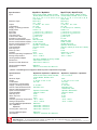
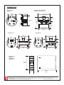
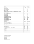
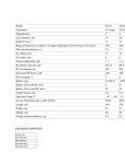
MP82710H & MP88710H
MP82710 & MP88710
MP82810 & MP88810
MP82820-R & MP88820-R
Mp82830-R
Mp82820-T & Mp88820-T
Mp82830-T
S-Products B.V. Nijverheidscentrum 26, NL-2761JP Zevenhuizen, The Netherlands, Tel: +31 180 633455 , Fax: +31 180 633644
S-Products Inc. 141 Kings Highway East, Fairfield, CT 06825, USA, Tel: +1 203 331 9546, Fax: +1 203 335 2723
E-mail: [email protected] Internet: www.s-products.com
Document No. Manual MP 2-wire.cdr - Issue 230713
CONTENTS
Type overview
Specifications
ATEX
Safety instructions
Connection diagram
Instructions for all Mp type transmitters
Programming instructions Mp Software
Dimensions
WARRANTY
Our transmitters have a 5 year warranty.
Follow usage instruction in this manual.
In case of malfunction return to your supplier.
SPECIFICATIONS
GENERAL INTRODUCTION:
Our Microprocessor based transmitters are divided in the 2 wire headmount series Mp82000, the rail mount
series Mp88000 and the 4 wire Mp87000. NOTE: The 4 wire transmitters are not described in this manual!
All models are easily programmed via a personal computer with our software and interface.
Model
Headmount
Mp82820-R
•
Mp82830-R
•
Railmount
2-wire
4-wire
RTD only
•
•
•
•
T/C only
All inputs
Isolated
Mp82820-T
•
•
•
Mp82830-T
•
•
•
Mp82810
•
•
•
Mp82710
•
•
•
•
Mp82710-H
•
•
•
•
Mp88820-R
•
•
Mp88820-T
•
•
Mp88810
•
•
•
Mp88710
•
•
•
•
Mp88710-H
•
•
•
•
Mp87800
•
•
•
Mp87700
•
•
•
Hart®
ATEX
*
•
*
•
•
*
•
*
•
* ATEX certification optionally available
S-Products B.V. Nijverheidscentrum 26, NL-2761JP Zevenhuizen, The Netherlands, Tel: +31 180 633455 , Fax: +31 180 633644
S-Products Inc. 141 Kings Highway East, Fairfield, CT 06825, USA, Tel: +1 203 331 9546, Fax: +1 203 335 2723
E-mail: [email protected] Internet: www.s-products.com
Document No. Manual MP 2-wire.cdr - Issue 230713
Specifications
Input
Mp82810 / Mp88810
Housing Material Mp82
Dimensions
Dimensions With Read-out
Zinc Alloy (ZAMAK 5), Epoxy coated
43mm Dia. x 27mm H.
43mm Dia. x 36mm H.
Housing Material Mp88
Dimensions
Makrolon
75mm H. X 22.5mm W x 99mm D.
RTD: Pt100, Pt250, Pt500, Pt1000
Ni100, Ni500, Ni1000, Cu10, Cu100
T/C: K, J, T, E, L, U, R, S, B, C, D, N
Volt & Ohm
RTD: 25 K
Minimum Span
T/C: 50 K
4...20 mA / 20...4 mA
Output
On / Off
Linearization
5...40 VDC
Supply *) Polarity protected
0.001% / V
Supply effect
+ 0.01%/°C or + 0.02°C/°C
Zero Drift
+ 0.01%/°C or + 0.01°C/°C
Span Drift
+ 0.05%/year
Long term Drift
+ 0.03 °C/°C
Cold Junction Drift
0.1 mA
Excitation Current RTD
Sensor Lead Resistance RTD 500 Ohm max.
Sensor Lead Resistance Effect 0.005 °C/Ohm
10,000 Ohm max.
Sensor Lead Resistance T/C
Upscale / Downscale
Open Circuit Detection
Vbat-5V / 20mA
Load Capability
5 sec
Start Up Time
2 min
Warm Up Time
none
Isolation
Ambient Operating Temperature -40°C...+85°C
-40°C...+100°C
Storage Temperature
Mp82710(H) / Mp88710(H)
RTD: Pt100, Pt250, Pt500, Pt1000
Ni100, Ni500, Ni1000, Cu10, Cu100
T/C: K, J, T, E, L, U, R, S, B, C, D, N
Volt & Ohm
RTD: 25 K
T/C: 50 K
4...20 mA / 20...4 mA
On / Off
5...40 VDC (H 12...40VDC)
0.003% / V
+ 0.01%/°C or + 0.02°C/°C
+ 0.01%/°C or + 0.02°C/°C
+ 0.05%/year
+ 0.03 °C/°C
0.1 mA
500 Ohm max.
0.005 °C/Ohm
10,000 Ohm max.
Upscale / Downscale
Vbat-5V / 20mA (H: Vbat-12V / 20mA)
5 sec
2 min
1500 V AC / 1 min.
-40°C...+85°C
-40°C...+100°C
*) NOTE: For ATEX approved equipment different power requirements may apply!
Specifications
Input
Minimum Span
Output
Linearization
Cold junction compensation
Supply *) Polarity protected
Sensor Lead Resistance RTD
Sensor Lead Resistance T/C
Open Circuit Detection
Load Capability
Start Up Time
Warm Up Time
Isolation
Ambient Operating Temperature
Storage Temperature
Housing Material Mp82820/30
Dim. Mp82820
Mp82830
Housing Dim. with cover
Housing Material Mp88
Dimensions
Mp82820-R / Mp82830-R / Mp88820-R
Mp82820-T / Mp82830-T / Mp88820-T
RTD: Pt100, Pt250, Pt500, Pt1000,
Ni100, Ni500, Ni1000, Ohm
25 K
4...20 mA or 20...4 mA
On / Off
T/C: K,J,T,E,N
5...40 VDC
500 Ohm max.
Upscale / Downscale
Vbat-5V / 20mA
5 sec
2 min
none
-40°C...+85°C
-40°C...+100°C
Makrolon
43mm Dia. x 23mm H.
43mm Dia. x 21mm H.
49mm Dia. x 25mm H.
50 K
4...20 mA or 20...4 mA
On / Off
On / Off
5...40 VDC
500 Ohm max.
10,000 Ohm max.
Upscale / Downscale
Vbat-5V / 20mA
5 sec
2 min
none
-40°C...+85°C
-40°C...+100°C
Makrolon
75mm H. X 22.5mm W x 99mm D.
S-Products B.V. Nijverheidscentrum 26, NL-2761JP Zevenhuizen, The Netherlands, Tel: +31 180 633455 , Fax: +31 180 633644
S-Products Inc. 141 Kings Highway East, Fairfield, CT 06825, USA, Tel: +1 203 331 9546, Fax: +1 203 335 2723
E-mail: [email protected] Internet: www.s-products.com
Document No. Manual MP 2-wire.cdr - Issue 230713
ATEX
GENERAL:
Some models of the MP series are available in an intrinsically
safe version and meet the requirements of the ATEX directive
94/9/EC.
MARKING:
All ATEX approved units carry the following labels:
S-Products BV
Mp8xx10-series
Nijverheidscentrum 26, NL-2761 JP
D E K R A 1 1 AT E X 010 5 X
0344
II 1 G
2011 .
Year of production
Serial No. i.e.:
Ex ia IIC T4/T5/T6 Ga See certificate for data
Ui < 30V Ii <100mA Pi < 750mW
+
C04164
S-Products
NETHERLANDS - SINGAPORE - USA
+
MODEL
RANGE
INPUT
OUTPUT
General product labels
POWER
Mp88710
0...1000°C
Thermocouple K
4...20 mA
10...40 V DC
2 - WIRE TRANSMITTER Mp 82710
INPUT
RANGE
Thermocouple K
0...1000°C
OUTPUT 4 - 20 mA
Certificate Number
Mp82710, Mp82710H, Mp88710, Mp88710H, Mp82000D
DEKRA 11ATEX0105 X
Parameters for products certified with certificate DEKRA 11ATEX0105 X:
Mp82710, Mp82710H, Mp88710, Mp88710H and Mp82000D:
Input circuit:
Supply circuit:
0344
II 1 G
Uo = 6,3 V DC
UI = 30 V DC
Ex ia IIC Ga
Io = 165 mA
II = 100 mA
T4 (Tamb -40...+85°C)
Po = 242 mW
PI = 750 mW
T5 (Tamb -40...+75°C)
Lo = 1 mH
LI = 0 mH
T6 (Tamb -40...+60°C)
Co = 34,5 µF
CI = 0 nF
Apparatus
without
further
specification
+
DC
POWER
ZENER
BARRIER
-
+
0344 = CE marking Notified Body
II = Group
1 G = Category 1, Gas
ia = intrinsic safety
IIC = Hydrogen and Acetylene Gas
T4...T6: Temperature Classification
EX
TRANSMITTER
SENSOR
-
NON-HAZARDOUS AREA
HAZARDOUS AREA
S-Products B.V. Nijverheidscentrum 26, NL-2761JP Zevenhuizen, The Netherlands, Tel: +31 180 633455 , Fax: +31 180 633644
S-Products Inc. 141 Kings Highway East, Fairfield, CT 06825, USA, Tel: +1 203 331 9546, Fax: +1 203 335 2723
E-mail: [email protected] Internet: www.s-products.com
Document No. Manual MP 2-wire.cdr - Issue 230713
NORMATIVE REFERENCE:
The transmitters Mp82710, Mp82710H, Mp88710, Mp88710H and plug-in display Mp82000D have an EC
Type examination certificate issued by DEKRA and have been approved to the following standards:
EN 60079-0 : 2012
EN 60079-11 : 2012
EN 60079-26 : 2007
SPECIAL CONDITIONS FOR SAFE USE:
For electrical data and temperature data see EC-Type examination certificate DEKRA 11ATEX0105 X
INSTALLATION REQUIREMENTS:
- ATEX approved equipment is only to be connected to a Zenerbarrier.
The Temperature Transmitter must be mounted in an enclosure providing a degree of ingress protection of at
least IP20 per EN 60529.
This enclosure must be in conformance with Clauses 4.3 and 4.4 of EN 50284, when the Temperature
Transmitter is mounted in an area where the use of category 1 G apparatus is required.
This enclosure must be in conformance with Clauses 7.3 and 8.1 of EN 50014, when the Temperature
Transmitter is mounted in an area where the use of category 2 G apparatus is required.
The mentioned Clauses describe how to avoid danger of ignition due to electrostatic charges.
- All transmitters Mp82000 and Mp88000 have an ingress protection of IP20.
This requires usage in a dry, clean and well controlled environment.
Mount the Mp82000 transmitter in a (DAN) head as described below..
- It is prefered to use twisted pair, shielded cable to connect the transmitter to its power supply in order to
obtain the best immunity to Electromagnetic signals. On the power supply side connect the shield to the
power supply’s earthing point, on the transmitter side connect the shield to the grounded head
somewhere close to the transmitter.
Make sure the transmitter is firmly connected to the head.
1
6
2
5
4
3
MOUNTING in CONNECTION HEAD
1. Screw M4
2. Transmitter
3. Measuring insert plate
4. Ferrule
5. Spring
6. Notch
S-Products B.V. Nijverheidscentrum 26, NL-2761JP Zevenhuizen, The Netherlands, Tel: +31 180 633455 , Fax: +31 180 633644
S-Products Inc. 141 Kings Highway East, Fairfield, CT 06825, USA, Tel: +1 203 331 9546, Fax: +1 203 335 2723
E-mail: [email protected] Internet: www.s-products.com
Document No. Manual MP 2-wire.cdr - Issue 230713
CONNECTIONS
Mp82820-R
DC
+
Power -
RTD
Mp82710(H) / Mp82810
+
Mp82830-R
+
DC
Power&
4-20mA
TC/mV
RTD
-
-
+
RTD
DC
Power
-
Interface connector
also used for connecting the optional display unit (Mp82810 / Mp82710(H) only).
Mp88820-R / Mp88820-T / Mp88810 / Mp88710(H)
Input signals
mV / TC
- +
RTD
Interface connector
behind removable
cover.
+ -
DC Power
and Output loopcurrent 4-20 mA
S-Products B.V. Nijverheidscentrum 26, NL-2761JP Zevenhuizen, The Netherlands, Tel: +31 180 633455 , Fax: +31 180 633644
S-Products Inc. 141 Kings Highway East, Fairfield, CT 06825, USA, Tel: +1 203 331 9546, Fax: +1 203 335 2723
E-mail: [email protected] Internet: www.s-products.com
Document No. Manual MP 2-wire.cdr - Issue 230713
General Instructions for the user
(not required for factory calibrated transmitters)
1. Insert the CD-ROM into your computer.
The Software will start automatically. (Or you may run MpUser_Setup_V44.exe)
Just follow the on-screen instructions.
Required is at least Windows 98 or NT and 1MB free space.
2. Connect the interface to the USB port of your computer.
Attach the interface to the transmitter.
Start the installed S-PRO Mp - software by clicking the "S"-icon.
First click Upload to read the settings from your transmitter.
Select the required parameters and download these into the transmitter.
3. After programming you may connect the transmitter as shown in the
connections drawing.
4. An optional display unit may be connected to the interface connector
(Mp82 and Mp87 series), after connecting power and a sensor.
HART® protocol transmitters
Selecting sensor and range can be done exactly the same as described before for all
our transmitters with the MP software.
In order to use HART protocol you need a HART compatible interface and software
or a handheld terminal.
Connect with a resistor in the loop as required by HART.
The transmitters know 14 universal commands and 5 common-practice commands:
0 Read unique identifier (ID)
1 Read primary variable
2 Read current and % of range
3 Read current and 4 (2) dynamic var
6 Write polling address
11 Read unique ID associated with tag
12 Read message
13 Read tag, descriptor, date
14 Read PV sensor information
15 Read output information
16 Read final assembly number
17 Write message
18 Write tag, descriptor, date
19 Write final assembly number
Note:
It is not possible to change °C into °F
or vice versa with a HART command.
Use the S-Pro Mp software to program
the transmitter
34 Write damping value
35 Write range values
40 Enter/Exit fixed current mode
49 Write PV sensor
59 Write # of response preambles
S-Products B.V. Nijverheidscentrum 26, NL-2761JP Zevenhuizen, The Netherlands, Tel: +31 180 633455 , Fax: +31 180 633644
S-Products Inc. 141 Kings Highway East, Fairfield, CT 06825, USA, Tel: +1 203 331 9546, Fax: +1 203 335 2723
E-mail: [email protected] Internet: www.s-products.com
Document No. Manual MP 2-wire.cdr - Issue 230713
S-PRO MpUser Software
General
This program uses the basic Windows® features like Save, Print, and Exit.
We refer to the Windows Help Manual for file handling.
Without a mouse you can reach the menu-items pressing both ALT
and the underlined key. You can jump between the settings with TAB.
Note that you will only get a
Sensor / Loopcurrent readout
on screen if the transmitter
is connected to a sensor.
1.
New Open Save Print
2.
3.
3. On-Screen
Readout
In the Sensor display
you'll see the actual
input value provided
the programmed
sensor is connected.
Loopcurrent is a
calculated value.
Click On to
start and Off
to stop the
on-screen display.
You must turn the
on-screen display
off before changing
settings.
Upload : Read the configuration from the transmitter.
1. File - Action - Settings
Download : Write your settings to the transmitter.
It is possible to save your settings for
later use, to open a previous configuration
or to print the present configuration. Either click on File or on one of the icons.
The large Upload and Download buttons are also located under Action.
With a transmitter connected use Upload to find out the settings of your transmitter.
After you made the required selections use Download to program the transmitter.
Settings is an important menu item. Here you can select °C or °F and the COM port. You can check which
COM-port has been assigned to the interface in your Windows Hardware Configuration Screen.
2. Settings
NOTE: Make sure to switch the on-screen readout Off, otherwise you can't alter the settings!
Transmitter : Use Upload to automatically detect transmitter model connected (connect transmitter first).
Sensor : You may select the input sensor from a list. The choice is limited by the transmitter type.
Thermocouple alloys are mentioned.
Minimum and Maximum : Input values for output current start and end.
Default are the range minimum and maximum of the selected sensor.
Tag 1 and Tag 2 : Any comment you'd like to add. (max. 16 characters)
Connection : The number of lead wires on your RTD sensor (i.e. Pt100).
Filter : Set to 50 Hz for Europe and 60 Hz for USA.
CJ Comp : Cold Junction Compensation for Thermocouples.
Sensor Break : Fixation of the loopcurrent on sensor malfunction.
Output Current : Choose min...max = 4...20 mA or 20...4 mA (Mp87000: The 0..1V/10V/0..20mA is automatic)
Linearization : Select On to linearize the input curve, or Off if you require the output curve to be
the same as the input.
Sample Rate : Select High for high sample rate, or Normal for standard sample rate.
S-Products B.V. Nijverheidscentrum 26, NL-2761JP Zevenhuizen, The Netherlands, Tel: +31 180 633455 , Fax: +31 180 633644
S-Products Inc. 141 Kings Highway East, Fairfield, CT 06825, USA, Tel: +1 203 331 9546, Fax: +1 203 335 2723
E-mail: [email protected] Internet: www.s-products.com
Document No. Manual MP 2-wire.cdr - Issue 230713
DIMENSIONS
Mp82710(H) with display
Mp82810 with display
Mp82710(H)
Mp82810
33 mm
1.30 "
5 mm
0.2 "
20 mm
0.79 "
47 mm 1.85 "
10 mm 0.4 "
17 mm
0.67 "
43.3 mm
1.70 "
36 mm
1.42 "
5 mm
0.2 "
M4
20 mm
0.79 "
43.3 mm
1.70 "
Mp82820-R
Mp82830-R
49 mm 1.93 "
49 mm 1.93 "
8 mm 0.31 "
33 mm
1.30 "
8 mm 0.31 "
33 mm
1.30 "
13 mm
0.51 "
25 mm
0.98 "
9 mm
0.35 "
13 mm
0.51 "
25 mm
0.98 "
5 mm
0.2 "
14 mm
0.55 "
14 mm
0.55 "
43 mm
1.69 "
43 mm
1.69 "
Mp88710(H)
Mp88810
Mp88820-R
Mp88820-T
75 mm
2.95 "
22.5 mm
0.89 "
99 mm
3.90 "
S-Products B.V. Nijverheidscentrum 26, NL-2761JP Zevenhuizen, The Netherlands, Tel: +31 180 633455 , Fax: +31 180 633644
S-Products Inc. 141 Kings Highway East, Fairfield, CT 06825, USA, Tel: +1 203 331 9546, Fax: +1 203 335 2723
E-mail: [email protected] Internet: www.s-products.com
Document No. Manual MP 2-wire.cdr - Issue 230713