1
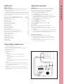
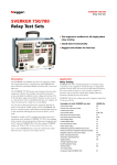
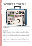
GE Energy
™
750
SVERKER
™
SVERKER 760
Relay Test Unit
Programma® Products
S VERKER 750 /76 0
SVERKER 750™/760™
Relay Test Unit
The Sverker 750/760™ Relay Test Unit is the engineer's toolbox. The control panel features a logical layout, still
SVERKER 650™ users will find it comfortably familiar and will be able to start work right away.
The SVERKER 750/760™ features many functions that make relay testing more efficient. For example, its powerful
measurement section can display (in addition to time, voltage and current) Z, R, X, S, P, Q, phase angle and cos φ. The
voltmeter can also be used as a 2nd ammeter (when testing differential relays for example). All values are presented
on a single easy-to-read display.
You can also test directional protective equipment efficiantly by means of the built-in variable voltage source. In
SVERKER 760™ this has a continuous phase shift function as well. Automatic reclosing devices can also be tested –
just as easily.
Designed to comply with EU standards and other personal and operational safety standards, SVERKER 750/760™
is also equipped with a serial port for communication with personal computers and the PC software SVERKER Win™.
Since the compact SVERKER™ weighs only 18 kg (39 lbs), it's easy to move from site to site.
Two or more SVERKER™ units can also be synchronized, which for example allows the user to connect three
SVERKER™ into a basic 3-phase test set.
Application example
Relay Testing
IMPORTANT!
Read the User’s manual before using the instrument.
SVERKER 750/760 is intended primarily for secondary testing of
protective relay equipment. Virtually all types of single-phase
protection can be tested.
SVERKER 750/760 is able to test three-phase protection that can
be tested one phase at a time, and also a number of protective relay
systems that require phase shifting. Moreover, automatic reclosing
devices can be tested.
Examples of what SVERKER 750/760 can test:
Overcurrent relays
Inverse time overcurrent relays
Undercurrent relays
Ground fault relays
Directional overcurrent relays
Directional ground fault relays
Overvoltage relays
Undervoltage relays
Directional voltage relays
Directional power relays
Power factor relays
Differential protection (differential circuits)
Distance protection equipment (phase by phase)
Negative sequence overcurrent relays
Motor overload protection
Automatic reclosing devices
Tripping relays
Voltage regulating relays
Overimpedance relays, Z>
Underimpedance relays, Z
Thermal relays
Time-delay relays
1.
2.
3.
4.
IEEE® No.
50/76
51
37
50
67
67N
59
27
91
32
55
87
21
46N
51/86
79
94
Other fields of application
•
•
•
•
•
•
•
Testing the pick-up and drop-out (SVERKER 760)
Plotting excitation curves
Current and voltage transformer ratio tests
Burden measurement for protective relay test equipment
Impedance measurement
Efficiency tests
Polarity (direction) tests
Injection
Maintained
Injection continues without any time limitation.
Momentary
Injection continues only as long as the button is
kept depressed.
Max. time
Injection stops automatically when the preset maximum
time is reached.
• Filtering
When filtering is selected, five successive readings are
averaged. The following can be filtered: Current, Voltage and
Extra items that are measured.
• Off delay
The turning off of generation can be delayed after tripping
throughout a specified time interval that is expressed in mainsfrequency cycles.
5.
6.
7.
8.
9.
10.
11.
12.
13.
14.
Connect as shown in the diagram.
Select stop conditions, dry or wet contact.
Select HOLD to freeze the current reading.
A until you get a red light at the built-in
Press button SEL/ô
ammeter. Note! Maximum allowed current through the separate
ammeter used in this connection example is 6 A. The other
measurement points do not have this limitation.
Press the MODE button.
Use the key M to select Ω, φ, W, VA...
Press CHG (Change)
Select φ (°, Iref) or (°, Uref) by using the key M.
Press SEL (Select)
Press ESC
Set the voltage amplitude with the upper small knob.
Make sure the main knob is set to 0.
Turn on the SVERKER output by activating ON using the start
switch M.
Set the phase-angle. Use the lower knob for fine adjustment, and
the middle knob for step of 90°. Note! A small current flowing in
the circuit is required to measure the phase angle.
Testing the operation time
15. Increase the current to 1.5 times the pick-up value.
16. Invoke the ON+TIME state by means of the start switch. The
outputs will now remain turned on until the protective relay
equipment operates.
17. Read the time from the display. Check also the high current
setting using the same procedure.
S VERKER 750 /76 0
Application
S VERKER 750 /76 0
❶ Set of resistors
Fine regulation of current and voltage are
easy thanks to the built-in set of resistors.
❷ Display
Presents time, current, voltage and other
entities. Also used to make many setting,
after you enter the setting mode by
pressing button marked MODE.
❸ Freeze function (HOLD)
This makes it possible to measure
voltages and current as short as a
quarter of a mains-voltage period by
immobilizing the reading on the display.
Voltage and current readings are frozen
when the timer stops. If the timer does
not stop, the reading present when the
current was interrupted is frozen on the
display.
❹ Start and stop conditions
The timer’s start and stop inputs respond
to changes, voltage or contact closing/
openings. The timer’s start input is also
used when testing auto-reclosing relays,
to synchronize two or more SVERKER
units and to start generation with an
external signal.
❺ Status indicator
The timer’s start and stop inputs are each
equipped with indicator lamps which,
when lighted, indicate a closed circuit
(useful for detecting contact closings/
openings) or the presence of voltage.
These indicator lamps make it possible
(for example) to check circuits before
starting a measurement cycle.
when the protective relay equipment
operates. When automatic reclosing is to
be tested, SVERKER an be set so that new
generation will start when the timer’s
start input is activated by the closing
command.
❽ Computer communication interface
SVERKER is equipped with a serial port for
communication with personal computers
and the PC software Sverker Win.
❾ Make/break contact
Changes state automatically when a test
is started. Can be used (for example) to
synchronize two or more SVERKER units,
other eternal equipment or to switch the
voltage applied to the protective relay
equipment back and forth between nonfaulty and faulty.
❿ Current source
Provides 0-250 A AC, 0-250 V AC or 0-300
V DC, depending on the output that is
being used. Settings are made using the
main knob. The readings of current,
voltage and other entities appear on the
display. The start switch is used to turn
the current source on and off. When time
is being measured, this is done in
synchronization with the timer.
⓫ Ammeter and voltmeter
Current and voltage are measured by the
built-in ammeter and voltmeter.
Resistance, impedance, phase angle,
power and power factor can also be
measured. Readings appear on the
display. These instruments can also be
used to take measurements in external
circuits. The voltmeter can also be used
as a 2nd ammeter (when testing
differential relays for example). Current
and voltage can be displayed either as
amperes and volts or as percentages of a
given current or voltage (the present
settings of the protective relay equipment
for example).
⓬ Auxiliary voltage source
Provides 20-220 V DC in two ranges.
Equipped with overload protection and
separated from the other outputs. Used
frequently to supply the object being
tested.
⓭ AC voltage source
Intended primarily for use with voltage
inputs to the protective relay equipment.
Can provide 0-140 V AC and 0-359° phase
shift (SVERKER 760). Since the AC voltage
source is separated from the other
outputs, it can be set independently of
the current source.
⓮ Tripping indicator
Lights when a stop condition is fulfilled to
indicate operation of the protective relay
equipment. If the test being conducted
incorporates timing, this indicator starts
to blink when relay operation occurs.
⓯ Main knob
Used to set current output from the
current source.
❻ Timer inputs
The timer has separate start and stop
inputs, and it can be used to measure
both external cycles and sequences
initiated by SVERKER. The measured time
appears on the display. Each input can be
set to respond to the presence or absence
of voltage (AC or DC) at a contact.
❼ Start switch
Controls the turning on and off of the
current source and timer. Can be set to
one of four states. ON+TIME. Starts
generation and timing simultaneously.
Used to test over... relays (...means
current, voltage or some other entity).
Generation continues a) until the
protective relay equipment operates and
stops the timer or b) until the maximum
time expires or the start switch is
released if time-limited generation has
been selected. OFF. Turns off the current
source, whereupon generation is
interrupted. ON. Turns on the current
source in the generating state. OFF+TIME.
Interrupts generation and starts the timer
simultaneously. Used when testing under
...relays (...means current, voltage or
some other entity). The timer is stopped
❿
❶
❾
❷
⓫
⓬
❸
❹
❺
⓮
❻
❼
⓯
❽
⓭
Phase Selector Switch
CSU20A
Current and Voltage Source
CSU20A is a small light-weight current and voltage source primarily
intended to work together with the SVERKER 750/760 Relay Testing
Unit when testing differential relays. Using the CSU20A together with
SVERKER 750/760 gives the user two independent current sources,
and the timer/measurement section in SVERKER 750/760 is used both
for measuring the two outputs as well as measuring the trip time of
the relay.
Besides testing differential relays the unit can be used as a multipurpose AC/DC source. The CSU20A features one AC current/voltage
output, one fully rectified DC output and one half-wave rectified DC
output for harmonic restraint testing.
Other features are a current measurement shunt, selectable
current/voltage ranges and an AC mains input/output. Connecting
the SVERKER 750/760 mains to the mains output of the CSU20A gives
an in-phase synchronization of the two units.
The PSS750 is specifically designed to work with SVERKER 750/760
when testing three-phase relays. It is connected between SVERKER
750/760 and the relay inputs and allows the user to easily select
which phase to test.
The PSS750 handles both the current and voltage sources and
single-phase or phase-phase testing can be selected. Together with
the output-input switching the unit also contains a variable resistor
that can be used together with the built-in capacitor in SVERKER
750/760. This feature gives the user the possibility to create a variable
phase shift at a decreased amplitude of the test voltage.
The design is passive which makes it very general. You may for
example use any of the inputs for current or voltage as long as you do
not exceed the specification. It is also possible to connect the
measuring inputs of the SVERKER 750/760 to the PSS750 and use the
switch for selecting measurement signals.
The PSS750 simplifies phase switching, selecting type of fault,
phase reversing and gives a possibility to create a variable phase shift.
Specifications CSU20A
Specifications PSS750
Specifications are valid at nominal input voltage and an ambient
temperature of +25°C, (77°F). Specifications are subject to change
without notice.
Operating temperature
-20°C to +50°C (-4°F to +122°F)
Mains voltage
115 / 230 V AC, 50 / 60 Hz
Thermal protection
Built-in
Dimensions
280 x 178 x 246 mm (11” x 7” x 9.7”)
Weight
5.9 kg (13 lbs) excl. transport case
Current measurements
Current shunt 0.1 A / 1 V, ± 2%
Specifications are valid at nominal input voltage and an ambient
temperature of +25°C, (77°F). Specifications are subject to change
without notice.
Max input voltage
250 V AC / 3 A
Max input current
6 A / 250 V AC
Max resistor loading
200 V AC / 200 mA (0.5 A during 5 seconds)
Dimensions
200 x 120 x 85 mm (7.9” x 4.7” x 3.3”)
Weight
1.3 kg (2.9 lbs)
Output, AC
20 A setting
Idle/non-load
5A
10 A
20 A
Output voltage (min)
26 V
25 V
22 V
18 V
Load time
Continuous
Continuous
Continuous
2 min
10 A setting
Idle/non-load
3A
5A
10 A
Output voltage (min)
52 V
50 V
47 V
41 V
Load time
Continuous
Continuous
Continuous
10 min
Output, DC
DC current
CSU20A
As above, less the voltage drop over the rectifying diodes
PSS750
S VERKER 750 /76 0
PSS750
Optional accessories
S VERKER 750 /76 0
Application example
IMPORTANT!
Read the User’s manual before using the instrument
1. Connect the current and voltage outputs of SVERKER 750/760 to
the PSS750 inputs.
2. Connect the current and voltage inputs of the relay to the PSS750
outputs.
3. Select which phase to test and type of test (phase-to-ground or
phase-phase) with the selector switch.
4. Proceed with the test for each phase and fault type.
5. To create a phase shift, connect the 10 μF capacitor in
SVERKER 750/760 in series between the voltage output and the
PSS750 input, and connect the variable resistor in parallel with
the PSS750 input.
6. Set the SVERKER 750/760 for phase (and impedance)
measurement. Connect the voltage measurement input to the
PSS750 input.
7. Start the test with the resistor in maximum position. Gradually
decreasing the resistor gives increasing phase shift in the voltage
signal. The test voltage/impedance will decrease at the same
time so an adjustment of the test current might be necessary to
get the correct impedance. Please observe that the phase shift
depends on the input resistance and may vary between different
relays. Some relays may also have a low voltage limit where the
relay will not operate. For additional 180 degrees phase shift use
the phase reversal switch.
SVERKER Win
PC software for SVERKER 750/760
The SVERKER Win software makes fieldwork easier while providing
neater reports. The SVERKER Win software enables you to control the
SVERKER from a PC. The SVERKER is connected to the PC’s serial port.
Test results can be reported either directly with table and graph, or
from an external program, e.g. Microsoft® EXCEL.
SVERKER Win enables customised reports in an easy way. Very
useful are the reference graphs, together with the current/voltage
graph presentation for each test point during the test. The graph can
of course be printed out on the test report if you like.
A new feature is the ready-made current curves available for
many relay types.
During relay testing, each measured value is stored in a log list. In
this list you can add comments to each test point. When the entire
test is finished, you can save everything as a data file. Later, you can
print out the test results. You save time by not having to write your
report in the field. All report writing can be done conveniently back at
the office.
The SVERKER Win software provides easy access to connection
instructions, test instructions and the like, which you prepare in
advance. These instructions, which can contain both text and
graphics, can be prepared using standard word processing packages.
The settings you make on SVERKER are also saved in a file, so that
the next time you want to test the same or similar protective relay
equipment, all you have to do in order to set-up the SVERKER, is to
open the file.
Specifications SVERKER Win
The SVERKER Win software comprises a 32-bit program written to run
under Windows® 95/98/2000/NT/XP. We recommend a Pentium®
computer with at least 16 MB of RAM. The amount of space needed to
save reports and settings will depend on how many protective
systems that are to be tested. Roughly estimated, you will thus need a
total of about 20-100 MB of free space on the hard disk. Languages in
SVERKER Win are: Czech, English, French, German, Spanish and
Swedish.
SVERKER Win
Specifications are valid at nominal input voltage and an ambient
temperature of +25°C, (77°F). Specifications are subject to change
without notice.
Environment
Application field
Temperature
Operating
Storage &
transport
Humidity
The instrument is intended for use in
high-voltage substations and industrial
environments.
0°C to +50°C (32°F to +122°F)
-40°C to +70°C (-40°F to +158°F)
5% – 95% RH, non-condensing
CE-marking
LVD
EMC
Low Voltage Directive 73/23/ EEC am.
by 93/68/EEC
EMC Directive 89/336/EEC am. by
91/263/EEC, 92/31/EEC and 93/68/EEC
Dimensions
Instrument
Transport case
Weight
SVERKER 750
SVERKER 760
Test lead set, with 4
mm stackable safety
plugs
Test leads with spadetonge connectors
Display
Available languages
Time can be displayed in seconds or in mains-frequency cycles.
Range
Resolution
Inaccuracy
000-9.999 s
1 ms
±(1 ms + 0.01%)*
10.00-99.99 s
10 ms
±(10 ms + 0.01 %)*
100.0-999.9 s
100 ms
±(100 ms + 0.01 %)*
* For the OFF+TIME start condition in INT mode, 1 ms shall be added
to the above measurement error.
Range
Resolution
0.0-999.9 cycles 0.1 cycles
1000-49999
1 cycle
cycles at 50 Hz
1000-59999
cycles at 60 Hz
Inaccuracy
±(0.1 cycles + 0.01%)
±(1 cycle + 0.01 %)
Ammeter
Measurement method
AC, true RMS
DC, mean value
Ranges
General
Mains voltage
Power consumption
(max)
Protection
Measurement section
Timer
115 / 230 V AC, 50 / 60 Hz
1380 W
Internal
External
0.00 – 250.0 A
0.000 – 6.000 A
Inaccuracy
Thermal cut-outs, automatic overload
protection
350 x 270 x 220 mm
(13.8” x 10.6” x 8.7”)
610 x 350 x 275 mm
(24.0” x 13.8” x 10.8”)
17.3 kg (38.1 lbs)
26.3 kg (58 lbs) with accessories and
transport case
17.9 kg (39.5 lbs)
26.9 kg (59.3 lbs) with accessories and
transport case
2 x 0.25 m (0.8 ft), 2.5 mm2
2 x 0.5 m (1.6 ft), 2.5 mm2
8 x 2.0 m (6.6 ft), 2.5 mm2
2 x 3.0 m (9.8 ft), 10 mm2
LCD
English, French, German, Spanish and
Swedish
Internal range 1)
0 – 10 A AC
0 – 40 A AC
0 – 100 A AC
External range 1)
0 – 0.6 A AC
0 – 6 A AC
0 – 0.6 A DC
0 – 6 A DC
±(1% + 20 mA)
±(1% + 40 mA)
±(1% + 200 mA)
±(1% + 20 mA)
±(1% + 20 mA)
±(0.5% + 2 mA)
±(0.5% + 20 mA)
Resolution
Internal range
External range
10 mA (range <100 A)
100 mA (range >100 A)
1 mA
Voltmeter
Measurement method
Range
Inaccuracy 1)
AC, true RMS
DC, mean value
0.00 – 600.0 V
AC, ±(1% + 200 mV) Max. value
DC, ±(0.5% + 200 mV) Max. value
Values are range depending
S VERKER 750 /76 0
Specifications SVERKER 750 / 760
S VERKER 750 /76 0
Extra measurements
Power factor and phase angle measurements
Range
Power factor cos φ -0.99 (cap) to
+0.99 (ind)
Phase angle φ (°)
000 – 359°
Resolution
0.01
Inaccuracy
±0.04
Range
1°
±2°
0 – 10 A
0 – 40 A
0 – 100 A
0 – 100 A
Impedance and power measurements
AC
DC
Range
Z (Ω and °), Z (Ω), R and X (Ω and Ω),
P (W), S (VA), Q (VAR)
R (Ω), P (W)
Up to 999 kX (X= unit)
Make / Break contact
Max. current
Max. voltage
1A
250 V AC or 120 V DC
Reclosing test
Items measured
Display
Tripping and reclosing times
After test is finished a list of all times
appears in display
Breaker state feedback The Make / Break contact can be used
to feed back the breaker state
Max. number of reclos- 49
ings
Max. testing time
999 s
Sets of resistors and a capacitor
Resistors
0.5 Ω to 2.5 kΩ
Capacitor 1)
10 μF, max voltage 450 V AC
1) Measurement intervals longer than 100 ms.
Outputs
Current outputs – AC
2) SVERKER 750
No-load
voltage
(min)
90 V
25 V
10 V
10 V
Full-load
voltage
(min)
75 V
20 V
8V
-
Full-load
current
(max)
10 A
40 A
100 A
250 A
Load / unload
times
On (max) / Off (min)
2 / 15 minutes
1 / 15 minutes
1 / 15 minutes
1 sec/ 5 minutes
Full-load
current
(max)
3A
2A
Load / unload
times
On (max) / Off (min)
10 min / 45 min
10 min / 45 min
Voltage outputs – AC / DC
Range
No-load
voltage
(min)
0 – 250 V AC 290 V AC
0 – 300 V DC 320 V DC
Full-load
voltage
(min)
250 V AC
250 V DC
Separate AC voltage source
SVERKER 750
Range
0 – 60 V AC
No-load voltage (min)
70 V
60 – 120 V AC 130 V
Full-load voltage (min)
60 V
Full-load current (max)
0.25 A
120 V
0.25 A
Both ranges are divided into voltage steps of 10 V that are steplessly
variable.
SVERKER 760
Range
0 – 130 V AC
No-load voltage (min)
140 V
Phase angle Resolution
0 – 359°
1°
Full-load voltage (min)
130 V
Full-load current (max)
0.25 A cont.
0.35 A, 1 minute
Inaccuracy
±2°
Auxiliary DC output
Range
Voltage
Max. current
20 – 130 V DC
20 V DC
130 V DC
130 V DC
220 V DC
300 mA
400 mA
235 mA
400 mA
130 – 220 DC
S VERKER 750 /76 0
Ordering information
SVERKER 750
Art.No.
Complete with:
Test lead set GA-00030
Transport case GD-00182
115 V Mains voltage
CD-11190
230 V Mains voltage
CD-12390
SVERKER 760
Complete with:
Test lead set GA-00030
Transport case GD-00182
115 V Mains voltage
CD-21190
230 V Mains voltage
CD-22390
Optional accessories
SVERKER Win PC Software
Please specify the SVERKER serial number when
ordering.
SVERKER Win contains software, a copy-protection
key and a cable used to connect the PC to SVERKER.
Note that the software key can be installed on a
single SVERKER. The software itself, however, can be
installed on an unlimited number of PCs.
CD-8102X
SVERKER Win Upgrade
CD-8101X
PROM* update, done by GE Energy
CD-89010
PROM* update, done by customer
CD-89011
* SVERKER Win requires PROM-version R04A or higher
CSU20A
Complete with cables and transport case
115 V Mains voltage
CSU20A
Complete with cables and transport case
230 V Mains voltage
PSS750
BF-41190
BF-42390
CD-90020
Test lead set
Programma Electric AB
Eldarvägen 4
SE-187 75 TÄBY
Sweden
Tel
Fax
E-mail
Internet
+46 8 510 195 00
+46 8 510 195 95
[email protected]
www.gepower.com
NOTICE OF COPYRIGHT & PROPRIETARY RIGHTS
© 2005, Programma Electric AB. All rights reserved.
The contents of this document are the property of Programma
Electric AB. No part of this work may be reproduced or transmitted
in any form or by any means, except as permitted in written
license agreement with Programma Electric AB.
Programma Electric AB has made every reasonable attempt
to ensure the completeness and accuracy of this document.
However, the information contained in this document is subject to
change without notice, and does not represent a commitment on
the part of Programma Electric AB.
TRADEMARK NOTICES
Programma® is a registered trademark of Programma Electric
AB. IEEE® is claimed as a registered trademark by the Institute
by Electrical Electronics Engineers, Inc. The GE logo is registered
trademark of General Electric Company.
All other brand and product names mentioned in this document
are trademarks or registered trademarks of their respective
companies.
Programma Electric AB is certified according to ISO 9001.
Subject to change without notice. Extract from catalog “Electrical Test Equipment” Art. No. ZG-9906E R100 GEA 13466A – ENG